JP6336575B2 - Respirator headgear - Google Patents

Respirator headgear Download PDF

Info

Publication number
JP6336575B2
JP6336575B2 JP2016510642A JP2016510642A JP6336575B2 JP 6336575 B2 JP6336575 B2 JP 6336575B2 JP 2016510642 A JP2016510642 A JP 2016510642A JP 2016510642 A JP2016510642 A JP 2016510642A JP 6336575 B2 JP6336575 B2 JP 6336575B2
Authority
JP
Japan
Prior art keywords
mask
headgear
strap
connection assembly
user
Prior art date
Legal status (The legal status is an assumption and is not a legal conclusion. Google has not performed a legal analysis and makes no representation as to the accuracy of the status listed.)
Active
Application number
JP2016510642A
Other languages
Japanese (ja)
Other versions
JP2016519958A (en
JP2016519958A5 (en
Inventor
ピーター デイヴィッド アレクサンダー ベアルン
ロヒート パテル
ロヒート パテル
キルスティン エリザベス ミッデルコープ
ファディ カリム モハメド マーシャル
ファディ カリム モハメド マーシャル
マイケル ジョン ヘンリー コックス
マイケル ジョン ヘンリー コックス
ブレア ライムンド ダッドソン マーフィー
Current Assignee (The listed assignees may be inaccurate. Google has not performed a legal analysis and makes no representation or warranty as to the accuracy of the list.)
Fisher and Paykel Healthcare Ltd
Original Assignee
Fisher and Paykel Healthcare Ltd
Priority date (The priority date is an assumption and is not a legal conclusion. Google has not performed a legal analysis and makes no representation as to the accuracy of the date listed.)
Filing date
Publication date
Application filed by Fisher and Paykel Healthcare Ltd filed Critical Fisher and Paykel Healthcare Ltd
Publication of JP2016519958A publication Critical patent/JP2016519958A/en
Publication of JP2016519958A5 publication Critical patent/JP2016519958A5/ja
Priority to JP2018088678A priority Critical patent/JP6981917B2/en
Application granted granted Critical
Publication of JP6336575B2 publication Critical patent/JP6336575B2/en
Active legal-status Critical Current
Anticipated expiration legal-status Critical

Links

Images

Classifications

    • AHUMAN NECESSITIES
    • A61MEDICAL OR VETERINARY SCIENCE; HYGIENE
    • A61MDEVICES FOR INTRODUCING MEDIA INTO, OR ONTO, THE BODY; DEVICES FOR TRANSDUCING BODY MEDIA OR FOR TAKING MEDIA FROM THE BODY; DEVICES FOR PRODUCING OR ENDING SLEEP OR STUPOR
    • A61M16/00Devices for influencing the respiratory system of patients by gas treatment, e.g. mouth-to-mouth respiration; Tracheal tubes
    • A61M16/06Respiratory or anaesthetic masks
    • A61M16/0683Holding devices therefor
    • AHUMAN NECESSITIES
    • A61MEDICAL OR VETERINARY SCIENCE; HYGIENE
    • A61MDEVICES FOR INTRODUCING MEDIA INTO, OR ONTO, THE BODY; DEVICES FOR TRANSDUCING BODY MEDIA OR FOR TAKING MEDIA FROM THE BODY; DEVICES FOR PRODUCING OR ENDING SLEEP OR STUPOR
    • A61M16/00Devices for influencing the respiratory system of patients by gas treatment, e.g. mouth-to-mouth respiration; Tracheal tubes
    • A61M16/06Respiratory or anaesthetic masks
    • A61M16/0605Means for improving the adaptation of the mask to the patient
    • A61M16/0616Means for improving the adaptation of the mask to the patient with face sealing means comprising a flap or membrane projecting inwards, such that sealing increases with increasing inhalation gas pressure
    • AHUMAN NECESSITIES
    • A62LIFE-SAVING; FIRE-FIGHTING
    • A62BDEVICES, APPARATUS OR METHODS FOR LIFE-SAVING
    • A62B18/00Breathing masks or helmets, e.g. affording protection against chemical agents or for use at high altitudes or incorporating a pump or compressor for reducing the inhalation effort
    • A62B18/08Component parts for gas-masks or gas-helmets, e.g. windows, straps, speech transmitters, signal-devices
    • A62B18/084Means for fastening gas-masks to heads or helmets
    • AHUMAN NECESSITIES
    • A61MEDICAL OR VETERINARY SCIENCE; HYGIENE
    • A61MDEVICES FOR INTRODUCING MEDIA INTO, OR ONTO, THE BODY; DEVICES FOR TRANSDUCING BODY MEDIA OR FOR TAKING MEDIA FROM THE BODY; DEVICES FOR PRODUCING OR ENDING SLEEP OR STUPOR
    • A61M16/00Devices for influencing the respiratory system of patients by gas treatment, e.g. mouth-to-mouth respiration; Tracheal tubes
    • A61M16/06Respiratory or anaesthetic masks
    • A61M16/0666Nasal cannulas or tubing
    • AHUMAN NECESSITIES
    • A61MEDICAL OR VETERINARY SCIENCE; HYGIENE
    • A61MDEVICES FOR INTRODUCING MEDIA INTO, OR ONTO, THE BODY; DEVICES FOR TRANSDUCING BODY MEDIA OR FOR TAKING MEDIA FROM THE BODY; DEVICES FOR PRODUCING OR ENDING SLEEP OR STUPOR
    • A61M2210/00Anatomical parts of the body
    • A61M2210/06Head
    • A61M2210/0618Nose
    • AHUMAN NECESSITIES
    • A61MEDICAL OR VETERINARY SCIENCE; HYGIENE
    • A61MDEVICES FOR INTRODUCING MEDIA INTO, OR ONTO, THE BODY; DEVICES FOR TRANSDUCING BODY MEDIA OR FOR TAKING MEDIA FROM THE BODY; DEVICES FOR PRODUCING OR ENDING SLEEP OR STUPOR
    • A61M2210/00Anatomical parts of the body
    • A61M2210/06Head
    • A61M2210/0625Mouth
    • AHUMAN NECESSITIES
    • A62LIFE-SAVING; FIRE-FIGHTING
    • A62BDEVICES, APPARATUS OR METHODS FOR LIFE-SAVING
    • A62B9/00Component parts for respiratory or breathing apparatus
    • A62B9/04Couplings; Supporting frames

Landscapes

  • Health & Medical Sciences (AREA)
  • General Health & Medical Sciences (AREA)
  • Pulmonology (AREA)
  • Life Sciences & Earth Sciences (AREA)
  • Emergency Medicine (AREA)
  • Biomedical Technology (AREA)
  • Heart & Thoracic Surgery (AREA)
  • Hematology (AREA)
  • Engineering & Computer Science (AREA)
  • Animal Behavior & Ethology (AREA)
  • Anesthesiology (AREA)
  • Public Health (AREA)
  • Veterinary Medicine (AREA)
  • Business, Economics & Management (AREA)
  • Emergency Management (AREA)
  • Respiratory Apparatuses And Protective Means (AREA)
  • Orthopedics, Nursing, And Contraception (AREA)

Description

任意の優先権出願の参照による援用
本願と共に提出された出願データシートにおいて、海外または国内優先権の主張が特定される一部またはすべての出願は、参照により本明細書に援用され、本開示の一部をなす。
INCORPORATION-BY-REFERENCE OF ANY PRIORITY APPLICATIONS Some or all applications for which an overseas or national priority claim is identified in an application data sheet filed with this application are hereby incorporated by reference and are incorporated herein by reference. Part of it.

本発明は、概して、呼吸マスクのヘッドギアに関する。より詳細には、本発明の特定の態様は、鼻の下および口のまわりで封止する呼吸マスクと共に使用されるヘッドギアに関する。   The present invention relates generally to respiratory mask headgear. More particularly, certain aspects of the invention relate to headgear for use with a respiratory mask that seals under the nose and around the mouth.

呼吸マスクには多数の異なる構成がある。呼吸マスクを使用者に固定するために、ヘッドギアをマスクに取り付けることができる。様々な方式のヘッドギアが利用可能である一方で、理想的には、ヘッドギアおよび呼吸マスクが協同して、所望の接続アセンブリを形成する。   There are many different configurations for respiratory masks. Headgear can be attached to the mask to secure the breathing mask to the user. While various types of headgear are available, ideally the headgear and the respirator cooperate to form the desired connection assembly.

一部の構成では、使用者の口のまわり、および使用者の鼻の下面で封止するマスクを設けることができる。そのようなマスクは、使用者の鼻および口の両方に加圧空気流を供給することができる。一部の構成では、マスクは額支持体を削除することができ、これは、市販されている多くの鼻マスクおよび多くの口−鼻マスクとは異なっている。   In some configurations, a mask may be provided that seals around the user's mouth and under the user's nose. Such a mask can provide a flow of pressurized air to both the user's nose and mouth. In some configurations, the mask can remove the forehead support, which is different from many commercially available nasal masks and many mouth-nose masks.

そのようなマスクの場合、ヘッドギアは、いくつかの課題の1つまたは複数を解決しなければならない。例えば、鼻封止面は、使用者の鼻の下側面に当てて固定されなければならない。鼻封止面を鼻に当てて固定することは、鼻に余分な力を加えることなく、効果的な封止を促進する。これを達成するために、ヘッドギアは、鼻の下面に少なくとも部分的に垂直な力をマスクにもたせることができる。   For such a mask, the headgear must solve one or more of several challenges. For example, the nasal sealing surface must be fixed against the underside of the user's nose. Fixing the nasal sealing surface against the nose facilitates effective sealing without applying extra force on the nose. To accomplish this, the headgear can exert a force on the mask that is at least partially perpendicular to the underside of the nose.

一部の構成では、額支持体がないということは、マスクが顔面で揺動しやすいことを意味する。そのような構成では、ヘッドギアは、上部が鼻から離れて大きく揺動する、またはマスクの底部が顎から離れる方向に移動する可能性を低くするように、シールを顔面に均一に押し当てて保持することができる。   In some configurations, the absence of a forehead support means that the mask is likely to swing on the face. In such a configuration, the headgear holds the seal evenly against the face so that it is less likely to rock the top away from the nose or move the bottom of the mask away from the chin. can do.

態様は、マスクおよびヘッドギアを含む接続アセンブリに関する。マスクは、呼吸ガスの流れを囲み、かつ呼吸ガスの流れを使用者の口に供給するシールを含む。ヘッドギアは、使用者の顔面にマスクを固定する。ヘッドギアは、使用者の頬に接触し、かつマスクを使用者の顔面に対して支持する比較的剛性の部分を含む。比較的剛性の部分は、マスクの位置を維持し、およびヘッドギアの締め付けに呼応したシールの圧縮を制限するのに十分な剛性を有する。   An aspect relates to a connection assembly including a mask and headgear. The mask includes a seal that surrounds the flow of breathing gas and supplies the breathing gas flow to the user's mouth. The headgear fixes the mask to the user's face. The headgear includes a relatively rigid portion that contacts the user's cheek and supports the mask against the user's face. The relatively rigid portion has sufficient rigidity to maintain the position of the mask and limit the compression of the seal in response to headgear tightening.

一部の構成では、少なくとも各比較的剛性の部分の皮膚に接触する側に頬パッドが配置される。頬パッドは、形状化することができる。頬パッドは、比較的剛性の部分を支持することができる。   In some configurations, a cheek pad is disposed on the side of at least each relatively rigid portion that contacts the skin. The cheek pad can be shaped. The cheek pad can support a relatively rigid portion.

一部の構成では、ヘッドギアは、各比較的剛性の部分から使用者の耳の略上の位置に向かって後方に延びる上側アームまたはストラップをさらに含む。   In some configurations, the headgear further includes an upper arm or strap that extends rearwardly from each relatively rigid portion toward a position generally above the user's ear.

一部の構成では、ヘッドギアは、使用者の頭の頭頂骨領域を囲み、上側アームまたはストラップに連結された後部ハロー部分を含む。後部ハロー部分の一部分、上側アームまたはストラップ、およびマスクは協同して、前部ハロー部分を形成することができる。   In some configurations, the headgear includes a posterior halo portion that surrounds the parietal region of the user's head and is coupled to an upper arm or strap. The portion of the rear halo portion, the upper arm or strap, and the mask can cooperate to form the front halo portion.

一部の構成では、ヘッドギアは、各前部ハロー部分および後部ハロー部分の一部を形成する頂部ストラップと、後部ハロー部分の一部を形成する後部ストラップとを含む。   In some configurations, the headgear includes a top strap that forms part of each front halo portion and rear halo portion, and a rear strap that forms part of the rear halo portion.

一部の構成では、上側アーム、頂部ストラップ、および後部ストラップの少なくとも一部分は、比較的剛性の材料、または比較的非伸縮性の材料から構築される。   In some configurations, at least a portion of the upper arm, top strap, and rear strap are constructed from a relatively rigid material or a relatively non-stretchable material.

一部の構成では、ヘッドギアは剛性部の対を含み、各剛性部は、上側アーム、頂部ストラップの一部分、および後部ストラップの一部分を含み、各頂部ストラップおよび後部ストラップは、剛性部を互いに連結し、かつ前部ハロー部分および後部ハロー部分の調整を可能にする調整機構を含む。調整機構は可撓性ストラップを含むことができる。   In some configurations, the headgear includes a pair of rigid portions, each rigid portion includes an upper arm, a portion of the top strap, and a portion of the rear strap, each top strap and rear strap connecting the rigid portions to one another. And an adjustment mechanism that allows adjustment of the front halo portion and the rear halo portion. The adjustment mechanism can include a flexible strap.

一部の構成では、各剛性部は、軟質材料のパッドで覆われる。軟質材料のパッドは、剛性部にオーバモールドされることができる。   In some configurations, each rigid portion is covered with a pad of soft material. A pad of soft material can be overmolded to the rigid part.

一部の構成では、マスクは、回転連結器によってヘッドギアに対して支持される。マスクは、ヘッドギアに対して回転位置に固定することができる。マスクは、回転連結器に組み込まれたロックまたはデテント機構によって、回転位置に固定されることができる。一部の構成では、マスクは、ヘッドギアのストラップによって、回転位置に固定される。   In some configurations, the mask is supported relative to the headgear by a rotary coupler. The mask can be fixed in a rotational position with respect to the headgear. The mask can be fixed in the rotational position by a lock or detent mechanism incorporated in the rotary coupler. In some configurations, the mask is fixed in a rotational position by a headgear strap.

一部の構成では、少なくとも1つの迅速解放機構は、接続アセンブリの2つの部分を分離することで、接続アセンブリの周囲が開く、または大きくなるのを可能にする。迅速解放機構は、接続アセンブリの2つの部分間にテザーを含むことができる。テザーは弾性であってもよい。一部の構成では、迅速解放機構は、ヘッドギアをマスクに連結するクリップを含む。クリップは、マスクとの少なくとも2つの離間した係合点を画定することができる。一部の構成では、磁石連結器が、クリップをマスクに対して所定の位置に案内する。迅速解放機構は、ヘッドギアをマスクに連結するクリップを含むことができ、テザーは、クリップがマスクに固定される場合に、クリップとマスクとの間で見えなくすることができる。一部の構成では、迅速解放機構は解放バックルを含むことができる。   In some configurations, the at least one quick release mechanism separates the two portions of the connection assembly to allow the perimeter of the connection assembly to open or grow. The quick release mechanism can include a tether between the two portions of the connection assembly. The tether may be elastic. In some configurations, the quick release mechanism includes a clip that connects the headgear to the mask. The clip can define at least two spaced points of engagement with the mask. In some configurations, a magnet coupler guides the clip into place with respect to the mask. The quick release mechanism can include a clip that connects the headgear to the mask, and the tether can be invisible between the clip and the mask when the clip is secured to the mask. In some configurations, the quick release mechanism can include a release buckle.

一部の構成では、シールの位置は、比較的剛性の部分が連結されるマスクのフレームまたは支持構造部に対して調整可能である。シールの位置を調整するダイヤル式調整器を設けることができる。   In some configurations, the position of the seal is adjustable relative to the mask frame or support structure to which the relatively rigid portions are coupled. A dial type adjuster for adjusting the position of the seal can be provided.

態様は、マスクおよびヘッドギアを含む接続アセンブリに関する。マスクは、呼吸ガスの流れを囲み、かつ呼吸ガスの流れを使用者の口に供給するシールを含む。ヘッドギアは、マスクを使用者の顔面に固定する。閉ループ調整機構は、接続アセンブリの第1の部分を接続アセンブリの第2の部分に連結し、かつ閉ループを維持しながら、接続アセンブリの全周囲長を変えるために、縮小定位と伸長定位との間で移行可能である。縮小定位では、マスクは、使用者の顔面に支持され、および伸長定位では、接続アセンブリは、使用者の頭に対して着脱可能である。閉ループ調整機構の少なくとも一部分はマスクに配置される。   An aspect relates to a connection assembly including a mask and headgear. The mask includes a seal that surrounds the flow of breathing gas and supplies the breathing gas flow to the user's mouth. The headgear fixes the mask to the user's face. A closed loop adjustment mechanism connects the first portion of the connection assembly to the second portion of the connection assembly and varies between the reduced and extended positions to change the overall circumference of the connection assembly while maintaining the closed loop. Can be migrated. In reduced orientation, the mask is supported on the user's face, and in extended orientation, the connection assembly is detachable from the user's head. At least a portion of the closed loop adjustment mechanism is disposed on the mask.

一部の構成では、閉ループ調整機構は、接続アセンブリの周囲長の一部分を形成するループを含み、ループは、第1および第2の離間した位置でマスクに固定されて、第1の部分長さを画定することができ、ループは、第2の位置から外されて、第2の部分長さを画定することができ、第2の部分長さは、接続アセンブリの周囲長を長くするために、第1の部分長さよりも長い。一部の構成では、第2の位置は、ループを巻き付けることができる保持クリートであってもよい。一部の構成では、第2の位置は、ループに連結されたクリップが係合する開口またはバーであってもよい。第1の位置は、ループが通過する摩擦ガイドであってもよく、摩擦ガイドは、標準的な操作力に応じて、ループとマスクとの間の所望の相対位置を維持するために、ループと摩擦で係合する。   In some configurations, the closed loop adjustment mechanism includes a loop that forms a portion of the perimeter of the connection assembly, the loop being secured to the mask at first and second spaced apart positions to provide a first partial length. And the loop can be removed from the second position to define a second portion length, the second portion length for increasing the perimeter of the connection assembly , Longer than the first part length. In some configurations, the second position may be a holding cleat that can wrap the loop. In some configurations, the second location may be an opening or bar that engages a clip coupled to the loop. The first position may be a friction guide through which the loop passes, and the friction guide is responsive to a standard operating force to maintain a desired relative position between the loop and the mask. Engage with friction.

一部の構成では、閉ループ調整機構は、ヘッドギアをマスクに連結するクリップを含む。クリップは、マスクとの少なくとも2つの離間した係合点を画定することができる。一部の構成では、磁石連結器が、クリップをマスクに対して所定の位置に案内する。閉ループ調整機構は、クリップとマスクとの間にテザーを含むことができる。一部の構成では、テザーは弾性である。閉ループ調整部は、マスクの各側にクリップを含むことができ、およびテザーは、2つのクリップ間に延びることができる。一部の構成では、テザーは、クリップがマスクに固定される場合に、クリップとマスクとの間で見えなくなる。   In some configurations, the closed loop adjustment mechanism includes a clip that connects the headgear to the mask. The clip can define at least two spaced points of engagement with the mask. In some configurations, a magnet coupler guides the clip into place with respect to the mask. The closed loop adjustment mechanism can include a tether between the clip and the mask. In some configurations, the tether is elastic. The closed loop adjuster can include a clip on each side of the mask, and the tether can extend between the two clips. In some configurations, the tether becomes invisible between the clip and the mask when the clip is secured to the mask.

一部の構成では、閉ループ調整機構は、開状態と閉状態との間を移動可能な複数のセグメントを有する折り畳み式締め具を含む。一部の構成では、折り畳み式締め具の少なくとも2つのセグメントは、折り畳み式締め具の閉状態で入れ子にされる。一部の実施形態では、セグメントの1つは、略U字形状を画定し、およびセグメントの第2の1つは、折り畳み式締め具の閉状態において、U字形状のセグメントの中央空間内に配置される。一部の構成では、セグメントの1つは、マスクによって担持され、およびセグメントの第2の1つは、ヘッドギアによって担持される。ロック調整器は、折り畳み式締め具とヘッドギアとの相対位置の調整を可能にするために、セグメントの第2の1つとヘッドギアとの間に設けられ得る。一部の構成では、折り畳み式締め具は、閉状態でロックする。   In some configurations, the closed loop adjustment mechanism includes a foldable fastener having a plurality of segments that are movable between an open state and a closed state. In some configurations, at least two segments of the folding fastener are nested with the folding fastener closed. In some embodiments, one of the segments defines a generally U-shape and the second one of the segments is within the central space of the U-shaped segment in the closed state of the foldable fastener. Be placed. In some configurations, one of the segments is carried by the mask and the second one of the segments is carried by the headgear. A lock adjuster may be provided between the second one of the segments and the headgear to allow adjustment of the relative position of the foldable fastener and the headgear. In some configurations, the folding fastener locks in the closed state.

態様は、マスクおよびヘッドギアを含む接続アセンブリに関する。マスクは、呼吸ガスの流れを囲み、かつ呼吸ガスの流れを使用者の口に供給するシールを含む。ヘッドギアは、マスクを使用者の顔面に固定し、少なくとも1つの調整ループを含む。スライドバックルは、ヘッドギアの一部分を蛇行路内に受け入れ、かつ調整ループの一部分に連結されており、ヘッドギアの一部分に沿ってスライドバックルを移動させることで、調整ループの大きさが変わって、ヘッドギアの全体的な大きさが変わる。   An aspect relates to a connection assembly including a mask and headgear. The mask includes a seal that surrounds the flow of breathing gas and supplies the breathing gas flow to the user's mouth. The headgear secures the mask to the user's face and includes at least one adjustment loop. The slide buckle receives a part of the headgear in the meandering path and is connected to a part of the adjustment loop. By moving the slide buckle along the part of the headgear, the size of the adjustment loop is changed. The overall size changes.

一部の構成では、スライドバックルの移動を容易にするために、スライドバックルにプルタブが連結される。一部の構成では、使用していないときに、連結器がプルタブをスライドバックルに対して固定する。連結器は磁石連結器であってもよい。   In some configurations, a pull tab is coupled to the slide buckle to facilitate movement of the slide buckle. In some configurations, the coupler secures the pull tab against the slide buckle when not in use. The coupler may be a magnet coupler.

一部の構成では、プルタブは、スライドバックルに対して、スライドバックルの移動方向に移動できるように、スライドバックルにスライド可能に取り付けられる。   In some configurations, the pull tab is slidably attached to the slide buckle so that it can move relative to the slide buckle in the direction of movement of the slide buckle.

一部の構成では、少なくとも1つのクリップが、ヘッドギアをマスクに連結する。クリップは、マスクにテザーでつながれてもよい。   In some configurations, at least one clip connects the headgear to the mask. The clip may be tethered to the mask.

一部の実施形態では、クリップは、マスクとの少なくとも2つの離間した係合点を画定する。   In some embodiments, the clip defines at least two spaced points of engagement with the mask.

態様は、マスクおよびヘッドギアを含む接続アセンブリに関する。マスクは、呼吸ガスの流れを囲み、かつ呼吸ガスの流れを使用者の口に供給するシールを含む。ヘッドギアは、マスクを使用者の顔面に固定する。ヘッドギアは、縫い目に沿って連結されて継ぎ目を形成する材料の少なくとも2つの平坦部分から構築され、材料のその部分の縫い目は、同じ形状を有さないため、連結された場合に、引張り、および/または圧縮が材料内に誘発されて、ヘッドギアに輪郭となる形状を付与する。   An aspect relates to a connection assembly including a mask and headgear. The mask includes a seal that surrounds the flow of breathing gas and supplies the breathing gas flow to the user's mouth. The headgear fixes the mask to the user's face. The headgear is constructed from at least two flat portions of material that are connected along the seam to form a seam, and the seams of that portion of the material do not have the same shape, so that when connected, pull, and Compression is induced in the material to give the headgear a contoured shape.

一部の構成では、縫い目は、材料のその部分の縁部によって画定される。   In some configurations, the seam is defined by the edge of that portion of material.

一部の実施形態では、その部分間の連結部は、ヘッドギアの後部部分に沿って垂直方向に延びる。   In some embodiments, the connection between the portions extends vertically along the rear portion of the headgear.

態様は、マスクおよびヘッドギアを含む接続アセンブリに関する。マスクは、呼吸ガスの流れを囲み、かつ呼吸ガスの流れを使用者の口に供給するシールを含む。ヘッドギアは、マスクを使用者の顔面に固定する。ヘッドギアは、使用者の頭の頭頂骨領域を囲む後部ハロー部分を含み、ヘッドギアはマスクと協同して、使用者の頭の前頭骨領域を囲む前部ハロー部分を形成する。ヘッドギアは、比較的伸縮性の部分と比較的非伸縮性の部分とを含み、比較的非伸縮性の部分は、前部ハロー部分および後部ハロー部分の少なくとも一方を囲む。   An aspect relates to a connection assembly including a mask and headgear. The mask includes a seal that surrounds the flow of breathing gas and supplies the breathing gas flow to the user's mouth. The headgear fixes the mask to the user's face. The headgear includes a posterior halo portion that surrounds the parietal region of the user's head, and the headgear cooperates with the mask to form an anterior halo portion that encloses the frontal bone region of the user's head. The headgear includes a relatively stretchable portion and a relatively non-stretchable portion, and the relatively non-stretchable portion surrounds at least one of the front halo portion and the rear halo portion.

一部の構成では、比較的非伸縮性の部分は、各前部ハロー部分および後部ハロー部分を囲む。   In some configurations, a relatively non-stretchable portion surrounds each front halo portion and rear halo portion.

一部の構成では、前部ハロー部分および後部ハロー部分の一方または両方は周方向に調整可能である。   In some configurations, one or both of the front halo portion and the rear halo portion is adjustable in the circumferential direction.

一部の構成では、ブレーク−フィット(break−fit)アセンブリは、ヘッドギアが、標準構成と拡大構成との間で移行するのを可能にする。ブレーク−フィットアセンブリは、ヘッドギアの第1の部分とヘッドギアの第2の部分との間に分離部を含むことができ、第1および第2の部分は、標準構成において合体して保持され、拡大構成において離間される。第1および第2の部分は、磁石閉じ具によって合体して保持されることができる。   In some configurations, a break-fit assembly allows the headgear to transition between a standard configuration and an expanded configuration. The break-fit assembly can include a separation between the first portion of the headgear and the second portion of the headgear, the first and second portions being held together and enlarged in a standard configuration Separated in configuration. The first and second portions can be held together by a magnet closure.

一部の構成では、第1および第2の部分は、それぞれ第1および第2のフラップを含む。一部の構成では、第1および第2のフラップは、プリーツによって連結される。   In some configurations, the first and second portions include first and second flaps, respectively. In some configurations, the first and second flaps are connected by pleats.

一部の構成では、前部ハロー部分は、第1の位置でマスクの両側につながり、ヘッドギアは、ヘッドギアの両側にストラップをさらに含み、ストラップはそれぞれ、第1の位置から離間した第2の位置でマスクのそれぞれの側につながる。第1および第2の位置は、それぞれ上側および下側位置であってもよい。   In some configurations, the front halo portion is connected to both sides of the mask at a first position, the headgear further includes straps on both sides of the headgear, each strap being in a second position spaced from the first position. Connect to each side of the mask with. The first and second positions may be upper and lower positions, respectively.

一部の構成では、補強特徴部が、ヘッドギアの比較的伸縮性の部分に形成される、あるいは固定される。   In some configurations, the reinforcing feature is formed or secured to a relatively stretchable portion of the headgear.

態様は、マスクおよびヘッドギアを含む接続アセンブリに関する。マスクは、呼吸ガスの流れを囲み、かつ呼吸ガスの流れを使用者の口に供給するシールを含み、マスクは、細長いスロットを有する支持構造体を含む。ヘッドギアは、マスクを使用者の顔面に固定し、ヘッドギアは、マスクの細長いスロットを通り、かつ折り曲げられてループを形成する端部部分を含み、ループはマスクを支持する折り部を有し、端部部分は、マスクのヘッドギアに対する角度を調整するために、上方向または下方向に調整することができる。   An aspect relates to a connection assembly including a mask and headgear. The mask includes a seal that surrounds the flow of breathing gas and supplies the flow of breathing gas to the user's mouth, and the mask includes a support structure having an elongated slot. The headgear secures the mask to the user's face, the headgear includes an end portion that passes through an elongated slot in the mask and is folded to form a loop, the loop having a fold that supports the mask, The part can be adjusted upward or downward to adjust the angle of the mask to the headgear.

一部の構成では、端部部分は先細りの形状を画定する。   In some configurations, the end portion defines a tapered shape.

一部の構成では、端部部分は、マスクを所望の角度位置で固定するようにヘッドギアに連結することができる。   In some configurations, the end portion can be coupled to the headgear to secure the mask at a desired angular position.

一部の構成では、細長いスロットは直線状の形状である。   In some configurations, the elongated slot has a linear shape.

別の態様では、本発明は、上記の接続器または互換性を有する他の任意の接続器のいずれかで使用できるように構成された上記の接続アセンブリのいずれかのヘッドギアに関する。   In another aspect, the invention relates to a headgear of any of the above connection assemblies configured for use with any of the above connectors or any other compatible connector.

さらなる態様によれば、本発明は、任意の1つまたは複数の図面を参照して本明細書で説明される構成要素に存する。   According to a further aspect, the invention resides in a component described herein with reference to any one or more drawings.

本明細書および特許請求の範囲で使用される「含む(comprising)」という用語は、「少なくとも一部が〜で構成される」ということを意味する。「含む(comprising)」という用語を含む、本明細書および特許請求の範囲での各記述を解釈する場合に、この用語を前に置かれた1つまたは複数の特徴部以外の特徴部も存在し得る。「含む(comprise)」および「含む(comprises)」などの関連用語も同じように解釈されるべきである。   As used herein and in the claims, the term “comprising” means “consisting at least in part of”. When interpreting each description in this specification and claims, including the term “comprising”, there may be features other than the one or more features preceding the term Can do. Related terms such as “comprise” and “comprises” should be interpreted in the same way.

本発明はまた、本願の明細書で言及された、または示された部分、要素、および特徴部、ならびに/または発明の記載に、個別に、または集合的に広く存在し、任意の2つ以上の前記部分、要素、特徴、または発明の記載の任意またはすべての組み合わせに広く存在すると考えることができ、本発明が関連する技術分野で公知の均等物を有する特定の完全体が本明細書で言及され、そのような公知の均等物は、個々に説明された場合と同様に本明細書に援用されるものとする。   The invention also exists broadly, individually or collectively in the parts, elements and features and / or description of the invention referred to or shown in the present specification, and any two or more Specific parts having equivalents known in the technical fields to which the present invention pertains may be considered broadly found in any or all combinations of the foregoing parts, elements, features, or invention descriptions. Such known equivalents are hereby incorporated by reference as if individually set forth.

本発明は前述の通りであり、さらに、以下に単なる例として示される構造も想定する。   The present invention is as described above, and further assumes a structure shown as an example below.

本明細書では、特許明細書、他の外部文献、または他の情報源を参照し、これは、概ね、本発明の特徴を説明するために背景を提示することを目的とする。特に別途明記されない限り、そのような外部文献の参照は、任意の管轄に属するそのような文献またはそのような情報源が先行技術であることを、または当技術分野における技術常識の一部をなすことを認めたものと解釈すべきでない。   This specification refers to patent specifications, other external documents, or other sources of information, which are generally intended to provide a background to illustrate features of the present invention. Unless specified otherwise, references to such external documents refer to the prior art of such documents or such information sources in any jurisdiction or form part of the common general knowledge in the art. It should not be construed as an admission.

単なる例として示される以下の説明から、本発明のさらなる態様および利点が明らかになるであろう。   Further aspects and advantages of the present invention will become apparent from the following description, given by way of example only.

本開示のこれらの、および他の特徴、態様、および利点が、好ましい実施形態の図面を参照して説明されるが、これらの実施形態は例示することを意図されており、本開示を限定することを意図されていない。   These and other features, aspects, and advantages of the present disclosure will be described with reference to the drawings of the preferred embodiments, which are intended to illustrate and limit the present disclosure Not intended to be.

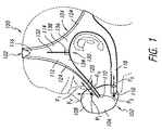
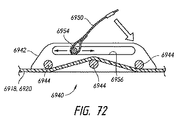
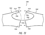
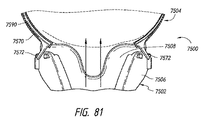
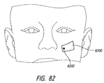
マスクなどの接続器およびヘッドギアを有する接続アセンブリの側面図である。1 is a side view of a connection assembly having a connector such as a mask and headgear. FIG. 図1の接続アセンブリの正面図である。FIG. 2 is a front view of the connection assembly of FIG. 1. 図1の接続アセンブリの背面図である。FIG. 2 is a rear view of the connection assembly of FIG. 1. 図1の接続アセンブリのヘッドギアの実現可能な様々な断面図を示している。Figure 2 shows various possible cross-sectional views of the headgear of the connection assembly of Figure 1; 図1の接続アセンブリのヘッドギアの実現可能な様々な断面図を示している。Figure 2 shows various possible cross-sectional views of the headgear of the connection assembly of Figure 1; 図1の接続アセンブリのヘッドギアの実現可能な様々な断面図を示している。Figure 2 shows various possible cross-sectional views of the headgear of the connection assembly of Figure 1; 図1の接続アセンブリのヘッドギアの実現可能な様々な断面図を示している。Figure 2 shows various possible cross-sectional views of the headgear of the connection assembly of Figure 1; 図1の接続アセンブリのヘッドギアの実現可能な様々な断面図を示している。Figure 2 shows various possible cross-sectional views of the headgear of the connection assembly of Figure 1; 図1の接続アセンブリのヘッドギアの実現可能な様々な断面図を示している。Figure 2 shows various possible cross-sectional views of the headgear of the connection assembly of Figure 1; 図1の接続アセンブリのブレーク−フィット機構を示している。Figure 2 shows a break-fit mechanism of the connection assembly of Figure 1; 図1の接続アセンブリのブレーク−フィット機構を示している。Figure 2 shows a break-fit mechanism of the connection assembly of Figure 1; マスクなどの接続器およびヘッドギアを有する接続アセンブリの側面図である。1 is a side view of a connection assembly having a connector such as a mask and headgear. FIG. マスクなどの接続器およびヘッドギアを有する接続アセンブリの側面図である。1 is a side view of a connection assembly having a connector such as a mask and headgear. FIG. 図7の接続アセンブリの正面図である。FIG. 8 is a front view of the connection assembly of FIG. 7. 図7の接続アセンブリの背面図である。FIG. 8 is a rear view of the connection assembly of FIG. 7. それぞれがマスクなどの接続器およびヘッドギアを有するいくつかの接続アセンブリの側面図である。FIG. 4 is a side view of several connection assemblies, each having a connector, such as a mask, and headgear. それぞれがマスクなどの接続器およびヘッドギアを有するいくつかの接続アセンブリの側面図である。FIG. 4 is a side view of several connection assemblies, each having a connector, such as a mask, and headgear. それぞれがマスクなどの接続器およびヘッドギアを有するいくつかの接続アセンブリの側面図である。FIG. 4 is a side view of several connection assemblies, each having a connector, such as a mask, and headgear. それぞれがマスクなどの接続器およびヘッドギアを有するいくつかの接続アセンブリの側面図である。FIG. 4 is a side view of several connection assemblies, each having a connector, such as a mask, and headgear. それぞれがマスクなどの接続器およびヘッドギアを有するいくつかの接続アセンブリの側面図である。FIG. 4 is a side view of several connection assemblies, each having a connector, such as a mask, and headgear. 図11A〜Cは、それぞれがマスクなどの接続器およびヘッドギアを有するいくつかの接続アセンブリの側面図である。11A-C are side views of several connection assemblies, each having a connector, such as a mask, and headgear. 図12A〜Iは、それぞれがマスクなどの接続器およびヘッドギアを有するいくつかの接続アセンブリの側面図である。12A-I are side views of several connection assemblies, each having a connector, such as a mask, and headgear. マスクなどの接続器およびヘッドギアを有する接続アセンブリの側面図である。1 is a side view of a connection assembly having a connector such as a mask and headgear. FIG. 図13の接続アセンブリの正面図である。FIG. 14 is a front view of the connection assembly of FIG. 13. 図13の接続アセンブリの背面図である。FIG. 14 is a rear view of the connection assembly of FIG. 13. マスクなどの接続器およびヘッドギアを有する接続アセンブリの側面図である。1 is a side view of a connection assembly having a connector such as a mask and headgear. FIG. マスクなどの接続器およびヘッドギアを有する接続アセンブリの側面図である。1 is a side view of a connection assembly having a connector such as a mask and headgear. FIG. マスクなどの接続器およびヘッドギアを有する接続アセンブリの側面図である。1 is a side view of a connection assembly having a connector such as a mask and headgear. FIG. 図18の接続アセンブリの回転調整器の分解図である。FIG. 19 is an exploded view of the rotation adjuster of the connection assembly of FIG. 18. マスクなどの接続器およびヘッドギアを有する接続アセンブリの側面図である。1 is a side view of a connection assembly having a connector such as a mask and headgear. FIG. マスクなどの接続器およびヘッドギアを有する接続アセンブリの側面図である。1 is a side view of a connection assembly having a connector such as a mask and headgear. FIG. マスクなどの接続器およびヘッドギアを有する接続アセンブリの側面図である。1 is a side view of a connection assembly having a connector such as a mask and headgear. FIG. マスクなどの接続器およびヘッドギアを有する接続アセンブリの側面図である。1 is a side view of a connection assembly having a connector such as a mask and headgear. FIG. マスクなどの接続器およびヘッドギアを有する接続アセンブリの側面図である。1 is a side view of a connection assembly having a connector such as a mask and headgear. FIG. 図23の接続アセンブリの正面図である。FIG. 24 is a front view of the connection assembly of FIG. マスクなどの接続器およびヘッドギアを有する接続アセンブリの側面図である。1 is a side view of a connection assembly having a connector such as a mask and headgear. FIG. マスクなどの接続器およびヘッドギアを有する接続アセンブリの側面図である。1 is a side view of a connection assembly having a connector such as a mask and headgear. FIG. 図26の接続アセンブリのヘッドギアの第1の部分の断面図である。FIG. 27 is a cross-sectional view of a first portion of the headgear of the connection assembly of FIG. 26; 図26の接続アセンブリのヘッドギアの第2の部分のいくつかの実現可能な断面図である。FIG. 27 is some possible cross-sectional views of a second portion of the headgear of the connection assembly of FIG. 26; 図26の接続アセンブリのヘッドギアの第2の部分のいくつかの実現可能な断面図である。FIG. 27 is some possible cross-sectional views of a second portion of the headgear of the connection assembly of FIG. 26; 図26の接続アセンブリのヘッドギアの第2の部分のいくつかの実現可能な断面図である。FIG. 27 is some possible cross-sectional views of a second portion of the headgear of the connection assembly of FIG. 26; マスクなどの接続器およびヘッドギアを有する接続アセンブリの側面図である。接続アセンブリは、マスクとヘッドギアとの間に回転連結器を有する。1 is a side view of a connection assembly having a connector such as a mask and headgear. FIG. The connection assembly has a rotary coupler between the mask and the headgear. 図29の接続アセンブリの回転連結器の分解図である。FIG. 30 is an exploded view of the rotary coupler of the connection assembly of FIG. 29. マスクなどの接続器およびヘッドギアを有する接続アセンブリの側面図である。ヘッドギアは頬パッドを含む。1 is a side view of a connection assembly having a connector such as a mask and headgear. FIG. The headgear includes a cheek pad. 図31の接続アセンブリのヘッドギアの頬パッド部分の斜視図である。FIG. 32 is a perspective view of the cheek pad portion of the headgear of the connection assembly of FIG. 31. マスクなどの接続器およびヘッドギアを有する接続アセンブリの側面図である。1 is a side view of a connection assembly having a connector such as a mask and headgear. FIG. マスクなどの接続器およびヘッドギアを有する接続アセンブリの側面図である。1 is a side view of a connection assembly having a connector such as a mask and headgear. FIG. マスクなどの接続器およびヘッドギアを有する接続アセンブリの側面図である。接続アセンブリは、ヘッドギアとマスクとの間に迅速解放機構を含む。1 is a side view of a connection assembly having a connector such as a mask and headgear. FIG. The connection assembly includes a quick release mechanism between the headgear and the mask. 代替の迅速解放機構の側面図である。FIG. 6 is a side view of an alternative quick release mechanism. マスクなどの接続器およびヘッドギアを有する接続アセンブリの側面図である。1 is a side view of a connection assembly having a connector such as a mask and headgear. FIG. マスクなどの接続器およびヘッドギアを有する接続アセンブリの側面図である。1 is a side view of a connection assembly having a connector such as a mask and headgear. FIG. 図38の接続アセンブリの背面図である。FIG. 39 is a rear view of the connection assembly of FIG. 38. マスクなどの接続器およびヘッドギアを有する接続アセンブリの側面図である。1 is a side view of a connection assembly having a connector such as a mask and headgear. FIG. マスクなどの接続器およびヘッドギアを有する接続アセンブリの側面図である。1 is a side view of a connection assembly having a connector such as a mask and headgear. FIG. 図41の接続アセンブリの正面図である。42 is a front view of the connection assembly of FIG. 41. FIG. マスクなどの接続器およびヘッドギアを有する接続アセンブリの側面図である。1 is a side view of a connection assembly having a connector such as a mask and headgear. FIG. マスクなどの接続器およびヘッドギアを有する接続アセンブリの側面図である。1 is a side view of a connection assembly having a connector such as a mask and headgear. FIG. 図44の接続アセンブリの正面図である。FIG. 45 is a front view of the connection assembly of FIG. 44. マスクなどの接続器およびヘッドギアを有する接続アセンブリの側面図である。1 is a side view of a connection assembly having a connector such as a mask and headgear. FIG. マスクなどの接続器およびヘッドギアを有する接続アセンブリの側面図である。ヘッドギアは、薄型調整機構を含む。1 is a side view of a connection assembly having a connector such as a mask and headgear. FIG. The headgear includes a thin adjustment mechanism. 図47の薄型調整機構の拡大図である。It is an enlarged view of the thin adjustment mechanism of FIG. マスクなどの接続器およびヘッドギアを有する接続アセンブリの側面図である。1 is a side view of a connection assembly having a connector such as a mask and headgear. FIG. マスクなどの接続器およびヘッドギアを有する接続アセンブリの斜視図である。接続アセンブリは、マスクとヘッドギアとの間に迅速解放機構を含む。1 is a perspective view of a connection assembly having a connector such as a mask and headgear. FIG. The connection assembly includes a quick release mechanism between the mask and the headgear. 代替の迅速解放機構を有する接続アセンブリの斜視図である。FIG. 6 is a perspective view of a connection assembly having an alternative quick release mechanism. 別の代替迅速解放機構を有する接続アセンブリの斜視図である。FIG. 10 is a perspective view of a connection assembly having another alternative quick release mechanism. さらに別の代替迅速解放機構を有する接続アセンブリの斜視図である。FIG. 10 is a perspective view of a connection assembly having yet another alternative quick release mechanism. さらに別の代替迅速解放機構を有する接続アセンブリの斜視図である。FIG. 10 is a perspective view of a connection assembly having yet another alternative quick release mechanism. クリップを含む別の代替迅速解放機構を有する接続アセンブリの斜視図である。FIG. 10 is a perspective view of a connection assembly having another alternative quick release mechanism including a clip. 図55の接続アセンブリのマスクの斜視図である。FIG. 56 is a perspective view of a mask of the connection assembly of FIG. 55. 図55の接続アセンブリの迅速解放機構のクリップの内側面の斜視図である。FIG. 56 is a perspective view of the inside surface of the clip of the quick release mechanism of the connection assembly of FIG. 55; 迅速解放機構を有する接続アセンブリの分解斜視図である。FIG. 6 is an exploded perspective view of a connection assembly having a quick release mechanism. クリップをマスクの残部に連結する伸縮性のテザーを含む迅速解放機構を有する接続アセンブリの斜視図である。FIG. 6 is a perspective view of a connection assembly having a quick release mechanism including a stretchable tether that connects the clip to the remainder of the mask. 伸縮性のテザーがある代替の迅速解放機構を有する接続アセンブリの斜視図である。FIG. 10 is a perspective view of a connection assembly having an alternative quick release mechanism with a stretchable tether. 伸縮性のテザーがある別の代替迅速解放機構を有する接続アセンブリの斜視図である。FIG. 10 is a perspective view of a connection assembly having another alternative quick release mechanism with a stretchable tether. 迅速解放機構が外れた状態にある図60の接続アセンブリの斜視図である。FIG. 61 is a perspective view of the connection assembly of FIG. 60 with the quick release mechanism disengaged. マスクなどの接続器およびヘッドギアを有する接続アセンブリの側面図である。接続アセンブリは、マスクとヘッドギアとの間に折り畳み式締め具迅速解放機構を含む。1 is a side view of a connection assembly having a connector such as a mask and headgear. FIG. The connection assembly includes a foldable fastener quick release mechanism between the mask and the headgear. 閉状態にある図62の折り畳み式締め具迅速解放機構の平面図である。FIG. 63 is a plan view of the foldable fastener quick release mechanism of FIG. 62 in a closed state. 開状態にある図62の折り畳み式締め具迅速解放機構の平面図である。FIG. 63 is a plan view of the foldable fastener quick release mechanism of FIG. 62 in an open state. ヘッドギアとマスクとを連結する代替の折り畳み式締め具迅速解放機構を有する接続アセンブリの斜視図である。折り畳み式締め具迅速解放機構が閉状態で示されている。FIG. 6 is a perspective view of a connection assembly having an alternative foldable fastener quick release mechanism for coupling headgear and mask. The folding fastener quick release mechanism is shown in the closed state. 折り畳み式締め具迅速解放機構が開状態にある図65の接続アセンブリの斜視図である。FIG. 66 is a perspective view of the connection assembly of FIG. 65 with the folding fastener quick release mechanism open. 図65の折り畳み式締め具迅速解放機構の断面図である。FIG. 66 is a cross-sectional view of the folding fastener quick release mechanism of FIG. 図65の接続アセンブリのヘッドギアストラップ調整アセンブリの拡大図である。FIG. 66 is an enlarged view of the headgear strap adjustment assembly of the connection assembly of FIG. 65. マスクなどの接続器およびヘッドギアを有する接続アセンブリの側面図である。スライドバックル調整機構がヘッドギアの調整を可能にする。1 is a side view of a connection assembly having a connector such as a mask and headgear. FIG. A slide buckle adjustment mechanism allows adjustment of the headgear. 図69のスライドバックル調整機構の断面図である。FIG. 70 is a sectional view of the slide buckle adjusting mechanism of FIG. 69. 図69のスライドバックル調整機構の斜視図である。FIG. 70 is a perspective view of the slide buckle adjustment mechanism of FIG. 69. スライド式プルタブを有する代替のスライドバックル調整機構の断面図である。FIG. 10 is a cross-sectional view of an alternative slide buckle adjustment mechanism having a sliding pull tab. 接合する前の形状化ヘッドギアの一部分を示している。A portion of the shaped headgear prior to joining is shown. 形状化ヘッドギアを形成するために接合された図73の部分を示している。FIG. 74 shows the portion of FIG. 73 joined to form a shaped headgear. マスクなどの接続器およびヘッドギアを有する接続アセンブリの前部斜視図である。ヘッドギアは、少なくとも1つの比較的剛性の部分を含む。1 is a front perspective view of a connection assembly having a connector, such as a mask, and headgear. FIG. The headgear includes at least one relatively rigid portion. 図75の接続アセンブリの側面図である。FIG. 76 is a side view of the connection assembly of FIG. 75. 図75の接続アセンブリの後部斜視図である。FIG. 76 is a rear perspective view of the connection assembly of FIG. 75. 図75のヘッドギアの頂部ストラップ部分内の調整機構の平面図である。FIG. 76 is a plan view of an adjustment mechanism within the top strap portion of the headgear of FIG. 75. 図75のヘッドギアの後部ストラップ部分内の調整機構の背面図である。FIG. 76 is a rear view of the adjustment mechanism in the rear strap portion of the headgear of FIG. 75. 調整機構の一部分を連結するテザーを備えたブレーク−フィット機構を有する図78および図79の代替調整機構の斜視図である。FIG. 80 is a perspective view of the alternative adjustment mechanism of FIGS. 78 and 79 having a break-fit mechanism with a tether connecting a portion of the adjustment mechanism. 締め付けられていないヘッドギア(左側)と締め付けられたヘッドギア(右側)との相違を示す、図75〜79の接続アセンブリの平面図である。FIG. 80 is a plan view of the connection assembly of FIGS. 75-79 showing the difference between an untightened headgear (left side) and a tightened headgear (right side). 図75〜79の接続アセンブリのヘッドギアの剛性部分の使用者の顔面上の接触位置を示す正面図である。80 is a front view showing a contact position on a user's face of a rigid portion of a headgear of the connection assembly of FIGS. 75 to 79; FIG. 図82の接触位置を示す平面図である。It is a top view which shows the contact position of FIG. 図75〜79の接続アセンブリのマスクの回転軸の位置を示す側面図である。FIG. 80 is a side view showing the position of the rotation axis of the mask of the connection assembly of FIGS. マスクの回転調整の範囲を示す、図75〜79の接続アセンブリのマスクの側面図である。FIG. 80 is a side view of the mask of the connection assembly of FIGS. 75-79 showing the range of rotation adjustment of the mask. 剛性部分およびパッドのいくつかの実現可能な形状を示す、図75〜79のヘッドギアの一部分の断面図である。FIG. 80 is a cross-sectional view of a portion of the headgear of FIGS. 75-79 showing some possible shapes of rigid portions and pads. 剛性部分およびパッドのいくつかの実現可能な形状を示す、図75〜79のヘッドギアの一部分の断面図である。FIG. 80 is a cross-sectional view of a portion of the headgear of FIGS. 75-79 showing some possible shapes of rigid portions and pads. 剛性部分およびパッドのいくつかの実現可能な形状を示す、図75〜79のヘッドギアの一部分の断面図である。FIG. 80 is a cross-sectional view of a portion of the headgear of FIGS. 75-79 showing some possible shapes of rigid portions and pads. 剛性部分およびパッドのいくつかの実現可能な形状を示す、図75〜79のヘッドギアの一部分の断面図である。FIG. 80 is a cross-sectional view of a portion of the headgear of FIGS. 75-79 showing some possible shapes of rigid portions and pads. 剛性部分およびパッドのいくつかの実現可能な形状を示す、図75〜79のヘッドギアの一部分の断面図である。FIG. 80 is a cross-sectional view of a portion of the headgear of FIGS. 75-79 showing some possible shapes of rigid portions and pads. 剛性部分およびパッドのいくつかの実現可能な形状を示す、図75〜79のヘッドギアの一部分の断面図である。FIG. 80 is a cross-sectional view of a portion of the headgear of FIGS. 75-79 showing some possible shapes of rigid portions and pads. 剛性部分およびパッドのいくつかの実現可能な形状を示す、図75〜79のヘッドギアの一部分の断面図である。FIG. 80 is a cross-sectional view of a portion of the headgear of FIGS. 75-79 showing some possible shapes of rigid portions and pads. 前部ハロー部分および後部ハロー部分を示す、図75〜79のヘッドギアの側面図である。FIG. 80 is a side view of the headgear of FIGS. 75-79 showing a front halo portion and a rear halo portion. 前部ハロー部分および後部ハロー部分をそれぞれが有する、図87に対する代替のヘッドギア構成を示している。FIG. 90 shows an alternative headgear configuration for FIG. 87, each having a front halo portion and a rear halo portion. 前部ハロー部分および後部ハロー部分をそれぞれが有する、図87に対する代替のヘッドギア構成を示している。FIG. 90 shows an alternative headgear configuration for FIG. 87, each having a front halo portion and a rear halo portion. 前部ハロー部分および後部ハロー部分をそれぞれが有する、図87に対する代替のヘッドギア構成を示している。FIG. 90 shows an alternative headgear configuration for FIG. 87, each having a front halo portion and a rear halo portion. 前部ハロー部分および後部ハロー部分をそれぞれが有する、図87に対する代替のヘッドギア構成を示している。FIG. 90 shows an alternative headgear configuration for FIG. 87, each having a front halo portion and a rear halo portion. 前部ハロー部分および後部ハロー部分をそれぞれが有する、図87に対する代替のヘッドギア構成を示している。FIG. 90 shows an alternative headgear configuration for FIG. 87, each having a front halo portion and a rear halo portion. 前部ハロー部分および後部ハロー部分をそれぞれが有する、図87に対する代替のヘッドギア構成を示している。FIG. 90 shows an alternative headgear configuration for FIG. 87, each having a front halo portion and a rear halo portion. 図75〜79のヘッドギアなどのヘッドギア内のブレーク−フィットアセンブリのいくつかの実施可能な位置を示している。FIG. 80 illustrates several possible positions of a break-fit assembly in a headgear, such as the headgear of FIGS. 図75〜79のヘッドギアなどのヘッドギア内のブレーク−フィットアセンブリのいくつかの実施可能な位置を示している。FIG. 80 illustrates several possible positions of a break-fit assembly in a headgear, such as the headgear of FIGS. 図75〜79のヘッドギアなどのヘッドギア内のブレーク−フィットアセンブリのいくつかの実施可能な位置を示している。FIG. 80 illustrates several possible positions of a break-fit assembly in a headgear, such as the headgear of FIGS. 図75〜79のヘッドギアなどのヘッドギア内のブレーク−フィットアセンブリのいくつかの実施可能な位置を示している。FIG. 80 illustrates several possible positions of a break-fit assembly in a headgear, such as the headgear of FIGS. 図75〜79のヘッドギアなどのヘッドギア内のブレーク−フィットアセンブリのいくつかの実施可能な位置を示している。FIG. 80 illustrates several possible positions of a break-fit assembly in a headgear, such as the headgear of FIGS. 図75〜79のヘッドギアなどのヘッドギア内のブレーク−フィットアセンブリのいくつかの実施可能な位置を示している。FIG. 80 illustrates several possible positions of a break-fit assembly in a headgear, such as the headgear of FIGS. ヘッドギアの比較的剛性および比較的非剛性の部分のオプションの位置を示す、接続アセンブリ用のヘッドギアの側面図である。FIG. 6 is a side view of a headgear for a connection assembly showing optional positions of relatively rigid and relatively non-rigid portions of the headgear. マスクなどの接続器およびヘッドギアを有する接続アセンブリの側面図である。接続アセンブリは、マスクとヘッドギアとの間に回転連結器を含む。1 is a side view of a connection assembly having a connector such as a mask and headgear. FIG. The connection assembly includes a rotary coupler between the mask and the headgear. マスクなどの接続器およびヘッドギアを有する接続アセンブリの斜視図である。接続アセンブリは、マスクの位置用の調整機構を含む。1 is a perspective view of a connection assembly having a connector such as a mask and headgear. FIG. The connection assembly includes an adjustment mechanism for the position of the mask. マスクなどの接続器およびヘッドギアを有する接続アセンブリの斜視図である。接続アセンブリは、ヘッドギア内の頬パッドと、マスクとヘッドギアとの間の迅速解放機構とを含む。1 is a perspective view of a connection assembly having a connector such as a mask and headgear. FIG. The connection assembly includes a cheek pad in the headgear and a quick release mechanism between the mask and the headgear.

図1〜3を参照すると、接続アセンブリ100が示されている。接続アセンブリ100は、任意の適切な構成を有することができる。図示した接続アセンブリ100は、接続器部分または接続器102、およびヘッドギア部分またはヘッドギア104を含む。図示した接続器102は、鼻−口マスクであるが、一部の構成では、開示した実施形態の特定の特徴、態様、および利点を、それらに限定されるものではないが、フルフェースマスク、鼻マスク、鼻ピロー、口マスク、およびカニューレを含む任意のタイプの接続器と共に使用することができる。したがって、接続器102は、本明細書において、簡便に「マスク」とも称される。「マスク]という用語の使用は、接続器全体を包含することを意図され、明確に、または開示に関連して別途指摘されない限り、「接続器」という用語と置き換えることができる。鼻−口マスクの例は、国際公開第2013/066195号パンフレットに提示されており、この特許の全体は、参照により本明細書に援用される。   1-3, a connection assembly 100 is shown. The connection assembly 100 can have any suitable configuration. The illustrated connection assembly 100 includes a connector portion or connector 102 and a headgear portion or headgear 104. The illustrated connector 102 is a nasal-mouth mask, but in some configurations, certain features, aspects, and advantages of the disclosed embodiments may include, but are not limited to, a full face mask, It can be used with any type of connector, including nasal masks, nasal pillows, mouth masks, and cannulas. Therefore, the connector 102 is also simply referred to as “mask” in this specification. The use of the term “mask” is intended to encompass the entire connector and can be replaced by the term “connector” unless explicitly or otherwise pointed out in connection with the disclosure. An example of a nose-mouth mask is presented in WO2013 / 066195, the entirety of which is hereby incorporated by reference.

図示したマスク102は通常、シール108を支持する、フレーム106などの支持構造部を含む。マスク102(例えば、フレーム106および/またはシール108)は、供給管(図示せず)に接続することができ、供給管は、一部の構成において、エルボによってフレームに接続することができる。供給管を使用して、呼吸ガスをシール108を介して使用者に供給することができる。シール108、またはシール108とフレーム106との組み合わせは、供給管から呼吸ガスを受け入れるチャンバを画定することができる。   The illustrated mask 102 typically includes a support structure such as a frame 106 that supports the seal 108. Mask 102 (eg, frame 106 and / or seal 108) can be connected to a supply tube (not shown), which in some configurations can be connected to the frame by an elbow. A supply tube can be used to supply breathing gas to the user via seal 108. The seal 108, or a combination of the seal 108 and the frame 106, can define a chamber that receives breathing gas from the supply tube.

上記のように、一部の構成では、マスク102は、使用者の口のまわり、および使用者の鼻の下面で封止することができる。そのようなマスク102は、使用者の鼻および口の両方に加圧空気流を供給することができる。そのようなマスク102の場合、ヘッドギア104は、鼻封止面を使用者の鼻の下側面に当てて固定するのが好ましい。鼻封止面を鼻に当てて固定することは、鼻に余分な力を加えることなく、効果的な封止を促進する。マスク102のチャンバ内の空気圧が上昇すると、ヘッドギア104によって加えられる力は、マスク102が顔面から持ち上がるのを阻止しようとする。マスク102が、使用者の鼻の下面に当てて封止される結果として、空気圧によってマスク102に加えられる力は下向きの成分を有する。しかし、通常では、力の最も大きい成分は、使用者の顔面から離れる方向に向けられる。空気圧によりマスクに作用する力に対処するために、ヘッドギア104は、少なくとも小さい上向きの成分を有する力をマスク102に付与するのが好ましい。一部の構成では、ヘッドギア104は、使用者の鼻の下面に概ね、または実質的に垂直に向けられた力をマスク102に付与することができる。   As described above, in some configurations, the mask 102 can be sealed around the user's mouth and under the user's nose. Such a mask 102 can provide a flow of pressurized air to both the user's nose and mouth. For such a mask 102, the headgear 104 is preferably secured with the nasal sealing surface against the underside of the user's nose. Fixing the nasal sealing surface against the nose facilitates effective sealing without applying extra force on the nose. As the air pressure in the chamber of the mask 102 increases, the force applied by the headgear 104 attempts to prevent the mask 102 from lifting from the face. As a result of the mask 102 being sealed against the underside of the user's nose, the force applied to the mask 102 by air pressure has a downward component. However, normally, the component with the greatest force is directed away from the user's face. In order to cope with the force acting on the mask by the air pressure, the headgear 104 preferably applies a force having at least a small upward component to the mask 102. In some configurations, the headgear 104 can apply a force to the mask 102 that is directed generally or substantially perpendicular to the underside of the user's nose.

マスク102は、取付位置または取付点110を含むのが好ましい。取付点110は、フレーム106、シール108、導管、およびエルボの少なくとも1つに形成することができる。任意の適切な取付点110を使用して、マスク102とヘッドギア104との間の連結を容易にすることができ、これは下記に説明される。多くの場合、取付点110は、フレーム106またはシール108用の他の支持構造部などのマスク102の比較的剛性の部分に配置される。したがって、ヘッドギア104が、フレーム106上の取付点110で連結された上でのフレーム106についての言及は、例えば、シールハウジングなどの、ヘッドギア104が連結されるマスク102の任意の支持構造部にも当てはまり得る。   The mask 102 preferably includes an attachment location or attachment point 110. Attachment point 110 may be formed on at least one of frame 106, seal 108, conduit, and elbow. Any suitable attachment point 110 can be used to facilitate the connection between the mask 102 and the headgear 104, which will be described below. In many cases, the attachment point 110 is located on a relatively rigid portion of the mask 102, such as the frame 106 or other support structure for the seal 108. Thus, reference to the frame 106 with the headgear 104 connected at the attachment point 110 on the frame 106 also applies to any support structure of the mask 102 to which the headgear 104 is connected, such as, for example, a seal housing. Can be true.

一部の構成では、取付点110は、ヘッドギア104とマスク102との容易な連結および切り離しに寄与する。一部の構成では、ヘッドギア104およびマスク102は、ヘッドギア104が、通常、マスク102の1つまたは複数の構成要素から取り外しできないように共に連結される。一部の構成では、ヘッドギア104およびマスク102は一体に形成することができる。一部の構成では、2つの取付点110が、マスク102の両側に設けられ、鉛直方向またはマスク102の高さ方向に互いに離間する。   In some configurations, the attachment point 110 contributes to easy connection and disconnection between the headgear 104 and the mask 102. In some configurations, the headgear 104 and the mask 102 are coupled together such that the headgear 104 is typically not removable from one or more components of the mask 102. In some configurations, the headgear 104 and the mask 102 can be integrally formed. In some configurations, two attachment points 110 are provided on either side of the mask 102 and are spaced apart from each other in the vertical direction or the height direction of the mask 102.

一部の構成では、ヘッドギア104は、前部ハロー部分112および後部ハロー部分114を含むことができる。ヘッドギア104は、少なくとも後部ハロー部分114を含むのが好ましい。前部ハロー部分112は、使用者の顔面の前頭骨領域または上半分を概ね囲み、後方および下方向きの力に耐えるように構成することができる。後部ハロー部分114は、頭の頭頂骨領域を概ね囲み、前方および下方向きの力に耐えることができる。一部の構成では、後部ハロー部分114は、マスク102に連結された場合に、使用時にマスク102加えられる力の大きさおよび/または方向の大部分または全体に耐えることができる。したがって、一部の構成では、後部ハロー部分114は、前部ハロー部分112なしで利用することができる。しかし、前部ハロー部分112は、使用者の頭を軸として接続アセンブリ100が回転するのを阻止または防止するのに寄与することができる。前部ハロー部分112はまた、マスク102の重量を支持するために下向きの力に耐え、例えば、ホースの引張り力などの他の概ね下向きの力に耐えることができる。したがって、多数の応用例において、前部ハロー部分112を使用することが望ましい。一部の構成では、前部ハロー構造部112および後部ハロー構造部114は、通常互いに隣接する。一部のそのような構成では、前部ハロー構造部112および後部ハロー構造部114は、共通頂部ストラップ116を共有することができる。   In some configurations, the headgear 104 can include a front halo portion 112 and a rear halo portion 114. The headgear 104 preferably includes at least a rear halo portion 114. The front halo portion 112 can be configured to generally surround the frontal bone region or upper half of the user's face and to withstand posterior and downward forces. The posterior halo portion 114 generally surrounds the parietal region of the head and can withstand forward and downward forces. In some configurations, the rear halo portion 114, when coupled to the mask 102, can withstand most or all of the magnitude and / or direction of the force applied to the mask 102 in use. Thus, in some configurations, the rear halo portion 114 can be utilized without the front halo portion 112. However, the front halo portion 112 can contribute to preventing or preventing the connection assembly 100 from rotating about the user's head. The front hello portion 112 can also withstand downward forces to support the weight of the mask 102 and can withstand other generally downward forces such as, for example, hose pulling forces. Accordingly, it is desirable to use the front halo portion 112 in many applications. In some configurations, the front halo structure 112 and the rear halo structure 114 are typically adjacent to each other. In some such configurations, the front halo structure 112 and the rear halo structure 114 may share a common top strap 116.

一部の構成では、耳下ストラップまたは耳ストラップ118は、ヘッドギア104の両側で後部ハロー部分114の下側部分から延びることができる。図示した構成に示すように、前部ハロー構造部112の下側または前部ストラップ部分120は、マスク102の両側の取付点110で、マスク102の上側部に取り付けることができる。前部ハロー構造部112の前部ストラップ部分120は、前部ストラップ部分120によって加えられる力が、上方向きの成分を有するように角度を付けることができる。上記のように、一部の構成では、力は、使用者の鼻の下面に略またはほとんど垂直とすることができる。そのような構成は、マスク102と使用者の鼻の下面との間に封止を形成するのに寄与することができる。取付位置および角度は、上記の課題の両方に対処する一助となる。   In some configurations, the sub-ear strap or ear strap 118 may extend from the lower portion of the rear halo portion 114 on both sides of the headgear 104. As shown in the illustrated configuration, the lower or front strap portion 120 of the front halo structure 112 can be attached to the upper portion of the mask 102 at attachment points 110 on either side of the mask 102. The front strap portion 120 of the front halo structure 112 can be angled so that the force applied by the front strap portion 120 has an upward component. As noted above, in some configurations, the force can be approximately or nearly perpendicular to the underside of the user's nose. Such a configuration can contribute to forming a seal between the mask 102 and the lower surface of the user's nose. The mounting position and angle help to address both of the above issues.

耳ストラップ118は、マスク102の両側の取付点110で、マスク102の下側部分に取り付けることができる。耳ストラップ118をマスク102の下側部分に取り付けることによって、耳ストラップ118によって加えられる力は、下記に説明するように、前部ハロー部分112の前部ストラップ部分120によって加えられる力と協同して、マスク102の角度位置に影響を及ぼす。前部ハロー部分112の前部ストラップ部分120は、耳ストラップ118との関係で「上側ストラップ」と称することができ、耳ストラップ118は、相対的に「下側ストラップ」であり、本明細書ではそのように称することができる。力をバランスさせることにより、マスクが揺動する可能性を低くすることができる。   Ear straps 118 can be attached to the lower portion of mask 102 at attachment points 110 on either side of mask 102. By attaching the ear strap 118 to the lower portion of the mask 102, the force applied by the ear strap 118 cooperates with the force applied by the front strap portion 120 of the front hello portion 112, as described below. Affects the angular position of the mask 102. The front strap portion 120 of the front hello portion 112 can be referred to as an “upper strap” in relation to the ear strap 118, which is relatively “lower strap” and is referred to herein. It can be called as such. By balancing the forces, the possibility of the mask swinging can be reduced.

図1を参照して、マスク102は、使用者の顔面に接触する上側点P1および下側点P2を有すると考えることができる。上側点P1は、概ね、または実質的に、使用者の鼻の下面と上唇との間の交差点に位置することができる。下側点P2は、使用者の顎に配置することができる。前部ストラップ部分120を調整することで、マスク102は、下側点P2のまわりに回転しようとする。耳ストラップ118を調整することで、マスク102は、上側点P1のまわりに回転しようとする。したがって、両方のストラップ118、120が存在することで、ヘッドギア104が適切に調整された場合に、いずれかの点P1、P2のまわりの望ましくない回転が阻止または防止されやすくなる。   With reference to FIG. 1, the mask 102 can be considered to have an upper point P1 and a lower point P2 that contact the face of the user. The upper point P1 can be located approximately or substantially at the intersection between the lower surface of the user's nose and the upper lip. The lower point P2 can be placed on the user's chin. By adjusting the front strap portion 120, the mask 102 attempts to rotate around the lower point P2. By adjusting the ear strap 118, the mask 102 attempts to rotate around the upper point P1. Thus, the presence of both straps 118, 120 tends to prevent or prevent undesired rotation about either point P1, P2 when the headgear 104 is properly adjusted.

ヘッドギア104は、上側ストラップ120を介してマスク102に力F1を加え、下側ストラップ118を介してマスク102に力F2を加えることができる。力F1は、水平に対して、または点P1、P2を通る線(またはマスクシール108上の上側点および下側点によって画定される線)に垂直な線に対して、少なくとも上方に向けることができる。力F2は、概ね後ろ方向水平とするか、あるいは点P1、P2を通る線(またはマスクシール108上の上側点および下側点によって画定される線)に垂直な線に沿うことができる。力F1は、約0°〜約90°とすることができる。ただし、空気圧のためにマスク102によってヘッドギア104に加えられる力は、主に使用者の顔面から離れる方向であるため、力F1の水平成分FHは、少なくとも、力F1の垂直成分FV以上であるのが好ましい。したがって、力F1の角度は約45°以下とすることができる。一方、使用者の鼻の下面に作用する封止力を大きくするなど、より大きい垂直成分FVが望ましい場合、力F1の角度を調整することができる。   The headgear 104 can apply a force F1 to the mask 102 via the upper strap 120 and a force F2 to the mask 102 via the lower strap 118. The force F1 may be directed at least upwards relative to the horizontal or perpendicular to a line passing through points P1, P2 (or a line defined by the upper and lower points on the mask seal 108). it can. The force F2 can be generally horizontal in the rearward direction, or can be along a line perpendicular to the line passing through points P1, P2 (or the line defined by the upper and lower points on the mask seal 108). The force F1 can be about 0 ° to about 90 °. However, since the force applied to the headgear 104 by the mask 102 due to air pressure is mainly in the direction away from the user's face, the horizontal component FH of the force F1 is at least equal to or greater than the vertical component FV of the force F1. Is preferred. Therefore, the angle of the force F1 can be about 45 ° or less. On the other hand, if a larger vertical component FV is desired, such as increasing the sealing force acting on the lower surface of the user's nose, the angle of the force F1 can be adjusted.

一部の構成では、マスク102に取り付けるために使用される上側ストラップ120および下側ストラップ118の1つまたは複数は長さを調整可能である。一部の構成では、上側ストラップ120および下側ストラップ118は共に長さを調整可能である。一方、図示した構成では、上側ストラップ120の長さは固定されており、前部ハロー部分112の全周は、中央調整特徴部122によって調整され、中央調整特徴部122は、後部ハロー部分114の周囲長も調整する。下側ストラップ118は、(上側ストラップ120の上側取付点110に対する)マスク102の回転位置が調整されるのを可能にするように調整することができる。   In some configurations, one or more of the upper strap 120 and the lower strap 118 used to attach to the mask 102 are adjustable in length. In some configurations, the upper strap 120 and the lower strap 118 are both adjustable in length. On the other hand, in the illustrated configuration, the length of the upper strap 120 is fixed, and the entire circumference of the front halo portion 112 is adjusted by the central adjustment feature 122, and the central adjustment feature 122 is arranged on the rear halo portion 114. Adjust the perimeter. The lower strap 118 can be adjusted to allow the rotational position of the mask 102 (relative to the upper attachment point 110 of the upper strap 120) to be adjusted.

一部の構成では、頂部ストラップ116は、中央調整特徴部122を有することができる。中央調整特徴部122は、ヘッドギア104の大きさを修正できるようにする。中央調整特徴部122は、任意の適切な構成を有することができる。一部の構成では、中央調整特徴部122は、バックル構成要素を含むことができ、頂部ストラップ116の一部分はバックルを通り、頂部ストラップ116の別の部分に重なることができる。一部の構成では、中央調整特徴部122は、2つの部分、頂部ストラップ116間に面連結器を設けるのと同程度に単純であり得る。   In some configurations, the top strap 116 can have a center adjustment feature 122. The center adjustment feature 122 allows the size of the headgear 104 to be modified. The center adjustment feature 122 can have any suitable configuration. In some configurations, the center adjustment feature 122 can include a buckle component, and a portion of the top strap 116 can pass through the buckle and overlap another portion of the top strap 116. In some configurations, the center adjustment feature 122 may be as simple as providing a face coupler between the two parts, the top strap 116.

ヘッドギア104は、任意の適切な材料で形成することができる。一部の構成では、ヘッドギア104の少なくとも一部分は、ある程度の伸縮を有する材料で作製される。一部の構成では、ヘッドギア104は、例えば、限定するものではないが、Breath−o−prene(登録商標)などの伸縮性材料で形成することができる。Breath−o−prene(登録商標)は、外側層がナイロンおよびスパンデックスからなるポリウレタン発泡体でできた加熱積層材料である。一部の構成では、ヘッドギア104は熱成形されて、構造部および支持部を形成することができる。   The headgear 104 can be formed of any suitable material. In some configurations, at least a portion of the headgear 104 is made of a material that has some degree of expansion and contraction. In some configurations, the headgear 104 can be formed of a stretchable material such as, but not limited to, Breath-o-plane (registered trademark). Breath-o-prene (registered trademark) is a heat-laminated material made of polyurethane foam whose outer layer is made of nylon and spandex. In some configurations, the headgear 104 can be thermoformed to form the structure and support.

ヘッドギア104はまた、非伸縮部124を含むことができる。一部の構成では、非伸縮部124は、ハロー部分112、114の一方または両方の周縁のまわりに延びることができる。図示した構成では、非伸縮部124は、前部ハロー部分112の全周(マスク102は除く)および後部ハロー部分114の全周に延びている。一部の構成では、非伸縮部はまた、下側ストラップ118に組み込むこともできる。非伸縮部124により、伸縮性材料による同様の構成と比較して、前部ハロー部分112および/または後部ハロー部分114が頭上で広がる可能性が低くなる。後部ハロー部分114が広がることで、マスク102が顔面から遠ざかる、または滑り落ちることがある。前部ハロー部分112が広がることで、使用者の頭を軸としたヘッドギア104の回転が可能になることがある。本明細書において、非伸縮部124との関連における「非伸縮」という用語は、ヘッドギア104の伸縮性の部分、または他の部分よりも伸縮性が小さい部分を指す。一部の構成では、非伸縮部124は、標準的な、または予測される力が、マスク102またはヘッドギア104に加えられたのに呼応した大きな伸縮、または伸長を阻止して、ハロー部分112、114を使用者の頭の所定の位置に保持することができるが、それでもなお、多少伸縮可能なことがある。非伸縮部124は、シール108の上側封止面が鼻から引き離される可能性を低くすることができる。一部の構成では、非伸縮部124は、ヘッドギア104の他の領域に組み入れることができる。伸縮性材料とは、通常ヘッドギアアセンブリで使用される材料を指すことがあり、または通常ヘッドギアアセンブリで使用される材料よりも大きい伸縮を示す材料を指すこともある。   The headgear 104 can also include a non-stretchable portion 124. In some configurations, the non-stretchable portion 124 can extend around the periphery of one or both of the halo portions 112, 114. In the illustrated configuration, the non-stretchable portion 124 extends all around the front halo portion 112 (excluding the mask 102) and all around the rear halo portion 114. In some configurations, the non-stretchable portion can also be incorporated into the lower strap 118. The non-stretchable portion 124 reduces the likelihood that the front halo portion 112 and / or the rear halo portion 114 will spread over the head as compared to a similar configuration of stretchable material. The spreading of the rear halo portion 114 may cause the mask 102 to move away from the face or slip off. The widening of the front halo portion 112 may allow the headgear 104 to rotate about the user's head. In the present specification, the term “non-stretching” in the context of the non-stretchable portion 124 refers to a stretchable portion of the headgear 104 or a portion that is less stretchable than other portions. In some configurations, the non-stretchable portion 124 prevents the halo portion 112, preventing large expansion or contraction in response to a standard or predicted force being applied to the mask 102 or headgear 104. 114 can be held in place on the user's head, but may still be somewhat stretchable. The non-stretchable part 124 can reduce the possibility that the upper sealing surface of the seal 108 is pulled away from the nose. In some configurations, the non-stretchable portion 124 can be incorporated into other regions of the headgear 104. Stretch material may refer to materials that are typically used in headgear assemblies, or may refer to materials that exhibit greater stretch than materials that are typically used in headgear assemblies.

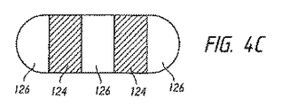
図4A〜4Fは、いくつかの実現可能なストラップ断面を示しているが、任意の適切なストラップ構成または構成の組み合わせを使用することができる。図4A〜4Fでは、斜線領域124は、ほとんど、または比較的非伸縮性または半剛性の材料を表すことができる。斜線のない領域126は、例えば、Breath−o−prene(登録商標)などの、より軟性の、および/またはより高い伸縮性/より低い剛性/より高い弾性の材料を表すことができる。図4A〜4Fに示す図解では、各断面の下側縁部は、患者の頭に接触する面を表すものである。ほとんどの構成では、患者の頭に接触する面の少なくとも一部は、より軟質の材料から、またはより軟質の材料で形成することができる。   4A-4F show some possible strap cross-sections, any suitable strap configuration or combination of configurations can be used. 4A-4F, the shaded region 124 can represent a little or relatively non-stretchable or semi-rigid material. Unshaded area 126 may represent a softer and / or higher stretch / lower stiffness / higher elastic material, such as, for example, Breath-o-prene®. In the illustrations shown in FIGS. 4A-4F, the lower edge of each cross-section represents the surface that contacts the patient's head. In most configurations, at least a portion of the surface that contacts the patient's head can be formed from a softer material or from a softer material.

図4Aでは、ストラップ断面は、ストラップの少なくとも1つの横縁部に、好ましくは各横縁部に非伸縮領域124を含む。伸縮領域126は、横方向に離間した非伸縮領域124間に延びている。図4Bでは、ストラップ断面は、中央非伸縮領域124を含み、伸縮領域126は、非伸縮領域124の両側にある。図4Cでは、ストラップ断面は、伸縮領域126と交互になった、複数の離間した非伸縮領域124を含む。図示した構成では、伸縮領域126は、各横縁部および中央に配置され、非伸縮領域124は、中央および縁部の伸縮領域126間にある。図4Dでは、非伸縮領域124は、ストラップ断面の幅方向に延びている。図示した構成では、領域は層化され、伸縮領域126は、非伸縮領域124の少なくとも一方の側、好ましくは両側にある。図4Eでは、非伸縮領域124および伸縮領域126は、ストラップの幅方向に延びており、それぞれが、ストラップ厚さの半分を占めている。図示した構成では、伸縮領域126は、使用者の頭に最も接近して配置されている。図4Fでは、ストラップ断面全体が伸縮領域126である。   In FIG. 4A, the strap cross-section includes a non-stretchable region 124 at at least one lateral edge of the strap, preferably at each lateral edge. The stretchable region 126 extends between the non-stretchable regions 124 that are spaced apart in the lateral direction. In FIG. 4B, the strap cross-section includes a central non-stretchable region 124 and the stretchable region 126 is on both sides of the non-stretchable region 124. In FIG. 4C, the strap cross-section includes a plurality of spaced apart non-stretchable regions 124 that alternate with stretchable regions 126. In the illustrated configuration, stretchable regions 126 are disposed at each lateral edge and center, and non-stretchable regions 124 are between the stretchable regions 126 at the center and edge. In FIG. 4D, the non-stretchable region 124 extends in the width direction of the strap cross section. In the illustrated configuration, the regions are stratified and the stretch region 126 is on at least one side, preferably both sides, of the non-stretch region 124. In FIG. 4E, the non-stretchable region 124 and the stretchable region 126 extend in the width direction of the strap, and each occupies half of the strap thickness. In the illustrated configuration, the stretchable region 126 is disposed closest to the user's head. In FIG. 4F, the entire strap section is the stretchable region 126.

図1、図5A、および図5Bを参照すると、一部の構成では、ヘッドギア104は、いわゆるブレーク−フィットアセンブリ130を含むことができ、ブレーク−フィットアセンブリ130は、ヘッドギア104が、マスク102を使用者の顔面に接触した状態に保持する密着状態または使用状態と、ヘッドギア104の着脱を容易にする取り付け状態または取り外し状態との間でヘッドギア104を移行させるために利用することができる。使用状態は、個々の使用者のために適切に調整された状態であり、ブレーク−フィットアセンブリ130は、使用状態と取り付け/取り外し状態との間のすばやくかつ容易な移行を可能にするのが好ましい。すなわち、接続アセンブリ100の取り付けごとに再調整する設計とは対照的に、ブレーク−フィットアセンブリ130は、ヘッドギア104が、適切に調整された状態のままであるが、着脱を容易にするために、特定の範囲まで拡張される、または開かれるのを可能にする。個々の使用者に合わせてヘッドギア104を調整できるようにするために、ブレーク−フィットアセンブリ130とは別の調整特徴部が設けられるのが好ましい。ブレーク−フィットアセンブリは、例えば、限定するものではないが、ヘッドギア104の任意のストラップ部分などのヘッドギア104の他の位置、または図89に対応するなどの本明細書で開示された任意の他の位置に設けることができる。   With reference to FIGS. 1, 5A, and 5B, in some configurations, the headgear 104 can include a so-called break-fit assembly 130 that uses the mask 102. It can be used to move the headgear 104 between a close contact state or a use state in which the headgear 104 is kept in contact with a person's face and an attachment state or a removal state in which the headgear 104 is easily attached or detached. The state of use is well tuned for the individual user, and the break-fit assembly 130 preferably allows a quick and easy transition between the state of use and the installed / removed state. . That is, in contrast to designs that readjust with each attachment of the connection assembly 100, the break-fit assembly 130 allows the headgear 104 to remain properly adjusted, but to facilitate attachment and detachment. Allows to be extended or opened to a certain range. In order to be able to adjust the headgear 104 for an individual user, an adjustment feature separate from the break-fit assembly 130 is preferably provided. The break-fit assembly may be any other location disclosed herein, for example, but not limited to, other positions of the headgear 104, such as any strap portion of the headgear 104, or corresponding to FIG. Can be provided in position.

ブレーク−フィットアセンブリ130は、ある種の条件下で伸長/拡張を阻止することができ、他の条件下で伸長/拡張を可能にする。例えば、ブレーク−フィットアセンブリ130は、自動式とすることができ、ブレーク−フィットアセンブリ130では、所定の、または望ましい降伏力を超えるまで、ヘッドギア104の伸長/拡張が阻止または防止され、超えた時点で、ヘッドギアは伸長/拡張することができる。一部の構成では、ブレーク−フィットアセンブリ130は、使用状態と取り付け/取り外し状態との間でヘッドギア104を移行させるように、手動で操作することができる。   Break-fit assembly 130 can prevent extension / expansion under certain conditions and allows extension / expansion under other conditions. For example, the break-fit assembly 130 can be automatic, where the extension / extension of the headgear 104 is prevented or prevented until a predetermined or desired yield force is exceeded, at which point the break-fit assembly 130 is exceeded. The headgear can be extended / expanded. In some configurations, the break-fit assembly 130 can be manually operated to transition the headgear 104 between a use state and an attached / removed state.

図示したブレーク−フィットアセンブリ130は、材料の第1のフラップ134と第2のフラップ136との間に分離部132を含む。図5Aおよび図5Bに示すように、第1のフラップ134および第2のフラップ136は、互いに接近させたそれぞれの縁部で隣接して、密着状態または使用状態を規定することができ、あるいはフラップ134、136は分離して、取り付け/取り外し状態を規定することができる。磁石閉じ具などの保持機構、留め具、または閉じ具138を利用して、フラップ134、136を密着状態または使用状態に固定されていてもよい。一部の構成では、フラップ134、136は、プリーツなどの、分離部132を画定する縁部間に延びる材料によって、互いに連結することができる。ヘッドギア102および/または接続アセンブリ100の取り付けを容易にする他の適切な機構を使用することもできる。例えば、ブレーク−フィットアセンブリは、例えば、限定するものではないが、2012年8月8日に出願された米国仮特許出願第61/681,024号明細書に記載された任意のものを含むことができ、この特許は、参照によりその全体が本明細書に援用される。   The illustrated break-fit assembly 130 includes a separator 132 between a first flap 134 and a second flap 136 of material. As shown in FIGS. 5A and 5B, the first flap 134 and the second flap 136 can be adjacent or adjacent to each other at the edges that are in close proximity to each other to define a tight or in use condition. 134, 136 can be separated to define the attachment / removal state. The flaps 134 and 136 may be fixed to a close contact state or a use state by using a holding mechanism such as a magnet closing member, a fastener, or a closing member 138. In some configurations, the flaps 134, 136 can be coupled together by a material that extends between the edges that define the separation 132, such as pleats. Other suitable mechanisms that facilitate attachment of headgear 102 and / or connection assembly 100 may also be used. For example, a break-fit assembly may include, for example, but is not limited to, any of those described in US Provisional Patent Application No. 61 / 681,024 filed Aug. 8, 2012. This patent is hereby incorporated by reference in its entirety.

図6を参照すると、別の接続アセンブリ600が、本開示の特定の特徴、態様、および利点に従って配置および構成されている。図示した接続アセンブリ600は、接続器602、およびヘッドギア604を含む。図示した接続器602は鼻−口マスクであるが、本明細書で説明したように、他のタイプの接続器を、開示したヘッドギア604と併用することができる。図示したマスク602は、通常、シール608を支持するフレーム606を含む。マスク602は、呼吸ガスを使用者に供給するために使用することができる供給管(図示せず)に接続することができる。上記のように、一部の構成では、マスク602は、使用者の口のまわり、および使用者の鼻の下面で封止することができる。そのようなマスク602は、使用者の鼻および口の両方に加圧空気流を供給することができる。ヘッドギア604は、下記に説明するように、1つまたは複数の取付位置または取付点610でマスク602に連結することができる。別途指摘されない限り、接続アセンブリ600または接続アセンブリ600の一部分の特徴部は、本明細書で説明した他の接続器または他の接続器の一部分と同じ、または同様とすることができ、あるいは別の適切な構成とすることもできる。   With reference to FIG. 6, another connection assembly 600 is arranged and configured in accordance with certain features, aspects, and advantages of the present disclosure. The illustrated connection assembly 600 includes a connector 602 and a headgear 604. The illustrated connector 602 is a nasal-mouth mask, but other types of connectors can be used with the disclosed headgear 604 as described herein. The illustrated mask 602 typically includes a frame 606 that supports a seal 608. The mask 602 can be connected to a supply tube (not shown) that can be used to supply breathing gas to the user. As described above, in some configurations, the mask 602 can be sealed around the user's mouth and under the user's nose. Such a mask 602 can provide a flow of pressurized air to both the user's nose and mouth. Headgear 604 can be coupled to mask 602 at one or more attachment locations or attachment points 610 as described below. Unless otherwise indicated, the features of connection assembly 600 or a portion of connection assembly 600 may be the same as or similar to other connectors or portions of other connectors described herein, or different Appropriate configurations can also be employed.

一部の構成では、ヘッドギア604は、概ね非伸縮性/半剛性のハロー状部分614(本明細書では「ハロー部分」と称する)を含むことができる。一部のそのような構成では、ハロー部分614は、使用者の頭の頭頂骨領域を概ね囲むことができる。一部のそのような構成では、ヘッドギア604は、使用者の顔面の両側でハロー部分614から前方に延びる剛性のフック状延長部またはフック部分612の形態の取付部分を有することができる。フック部分612は、使用者の耳の上および前に位置し、マスク602をハロー部分614に連結するための取付位置を提供するのが好ましい。   In some configurations, the headgear 604 can include a generally non-stretch / semi-rigid halo-like portion 614 (referred to herein as a “halo portion”). In some such configurations, the halo portion 614 can generally surround the parietal region of the user's head. In some such configurations, the headgear 604 can have a mounting portion in the form of a rigid hook-like extension or hook portion 612 that extends forward from the halo portion 614 on either side of the user's face. The hook portion 612 is preferably located above and in front of the user's ear and provides a mounting location for coupling the mask 602 to the halo portion 614.

ヘッドギア604は、マスク602をハロー部分614に連結する2つ以上のストラップを含むのが好ましい。図示した構成では、第1の、または下側ストラップ618、および第2の、または上側ストラップ620が、ヘッドギア604の両側に設けられて、マスク602をハロー部分614に連結し、マスク602の回転調整を可能にしている。図示したストラップ618、620は、マスク602をハロー部分614に間接的に連結している。ストラップ618、620は、ストラップ618、620からの力をハロー部分614に伝達するフック部分612に直接連結されている。一部の構成では、ストラップ618、620の1つまたは複数は、調整可能な長さ、または調整可能な有効長を有することができる。図示した構成では、各ストラップ618、620の実際の長さは固定されているが、フック部分612上のストラップ618、620の位置を変えて、フック部分612から前方に延びる各ストラップ618、620の長さを調整することができる。ストラップ618、620は、面ファスナ部分640と協同するなど、任意の適切な機構によって、フック部分612およびマスク602に固定することができる。ストラップ618、620の長さ調整量を大きくするために、フック部分612のかなりの部分を面ファスナ部分640で占めることができる。一部の構成では、ストラップ618、620の内側を向いた面の全体または実質的に全体は、面ファスナ部分640を含むことができる。   Headgear 604 preferably includes two or more straps that couple mask 602 to halo portion 614. In the illustrated configuration, a first or lower strap 618 and a second or upper strap 620 are provided on either side of the headgear 604 to connect the mask 602 to the halo portion 614 and adjust the rotation of the mask 602. Is possible. The illustrated straps 618, 620 indirectly couple the mask 602 to the halo portion 614. The straps 618, 620 are directly coupled to a hook portion 612 that transmits the force from the straps 618, 620 to the halo portion 614. In some configurations, one or more of the straps 618, 620 can have an adjustable length or an adjustable effective length. In the illustrated configuration, the actual length of each strap 618, 620 is fixed, but the position of the strap 618, 620 on the hook portion 612 is changed to allow each strap 618, 620 extending forward from the hook portion 612. The length can be adjusted. The straps 618, 620 can be secured to the hook portion 612 and the mask 602 by any suitable mechanism, such as in cooperation with the hook and loop fastener portion 640. To increase the length adjustment of the straps 618, 620, a significant portion of the hook portion 612 can be occupied by the hook and loop fastener portion 640. In some configurations, all or substantially the entire inward facing surface of the straps 618, 620 can include a hook and loop fastener portion 640.

一部の構成では、ハロー部分614は概ね半剛性である。一部のそのような構成では、半剛性のハロー部分614は、取り付け、または装着プロセスを容易にするために、ヘッドギア604が開いたままであるのに寄与することができる。一部のそのような構成では、半剛性のハロー部分614は、ヘッドギア自身の重量のためにヘッドギア604(特に、ハロー部分614)が潰れる可能性を低くすることができる。一部のそのような構成では、ハロー部分614の半剛性の特質は、ハロー部分614が、着用するのに不快な剛性ではないようにするのと同時に、取り付けを容易にする。   In some configurations, the halo portion 614 is generally semi-rigid. In some such configurations, the semi-rigid halo portion 614 can contribute to the headgear 604 remaining open to facilitate the attachment or mounting process. In some such configurations, the semi-rigid halo portion 614 can reduce the likelihood that the headgear 604 (particularly the halo portion 614) will collapse due to the weight of the headgear itself. In some such configurations, the semi-rigid nature of the halo portion 614 facilitates attachment while at the same time ensuring that the halo portion 614 is not uncomfortable to wear.

一部の構成では、ヘッドギア604のフック部分612は、ハロー部分614よりも高い剛性とすることができる。一部の構成では、フック部分612は、使用中の標準的な、または予測される力に呼応して耳の上で曲がる可能性を低くするのに十分な剛性とされる。マスク602の望ましくない移動は、フック部分612の大きな曲がりに起因することがある。   In some configurations, the hook portion 612 of the headgear 604 can be more rigid than the halo portion 614. In some configurations, the hook portion 612 is rigid enough to reduce the likelihood of bending over the ear in response to standard or anticipated forces in use. Undesirable movement of the mask 602 may be due to large bends in the hook portion 612.

一部の構成では、フック部分612のハロー部分614からの延長の元の部分642は、実質的に垂直とすることができる。一部の構成では、実質的に垂直の延長部642は、マスク602に対する望ましい力の角度を付けるのに寄与することができる。一部のそのような構成では、望ましい力の角度は、使用者の鼻の底部に沿ったマスク602の封止を促進する。   In some configurations, the original portion 642 of the hook portion 612 extending from the halo portion 614 can be substantially vertical. In some configurations, the substantially vertical extension 642 can contribute to the desired angle of force relative to the mask 602. In some such configurations, the desired force angle facilitates sealing of the mask 602 along the bottom of the user's nose.

上側ストラップ620は、角度をなしてフック部分612に取り付けることができる。一部のそのような構成では、角度は、使用者の鼻の下面に略垂直とすることができる。下側ストラップ618は、マスク602の底部に取り付けることができる。一部のそのような構成では、下側ストラップ618は、マスク602が、使用者の顎から離れる方向で上に持ち上がる可能性を低くすることができる。一部の構成では、下側ストラップ618および上側ストラップ620の1つまたは複数は、例えば、限定するものではないが、Breath−o−prene(登録商標)などの材料で、または材料から形成することができる。ストラップ618、620は、調整を容易にし、使用者の顔面に加えられる余分な力を最小限にするために、可撓性を付与する材料で、または材料から形成することができる。ストラップ618、620は、使用時にマスク602を使用者の顔面の所定の位置に維持するために、標準的な、または予測される力に呼応した、ストラップ618、620の軸方向に沿った伸長を少なくとも大幅に制限するのが好ましい。本明細書において、「軸」方向とは、ストラップ(または他の構成要素)の長手方向の幾何学軸と合致する方向、または関連する力が加えられる方向とすることができる。ストラップまたは他の構成要素の軸は、非直線状(例えば、曲線状)であってよい。一部の例では、複雑な形状を有するストラップまたは構成要素に関してなど、「軸」方向が幾何学軸と合致しないことがあるが、ストラップの端部または連結点で規定することができ、またはストラップまたは他の構成要素による抵抗力と概ね合致することができる。   The upper strap 620 can be attached to the hook portion 612 at an angle. In some such configurations, the angle can be substantially perpendicular to the underside of the user's nose. The lower strap 618 can be attached to the bottom of the mask 602. In some such configurations, the lower strap 618 can reduce the likelihood that the mask 602 will lift up in a direction away from the user's chin. In some configurations, one or more of the lower strap 618 and the upper strap 620 may be formed of or from a material such as, but not limited to, Breath-o-prene®. Can do. The straps 618, 620 can be formed of or from a material that imparts flexibility to facilitate adjustment and minimize extra force applied to the user's face. The straps 618, 620 can extend along the axial direction of the straps 618, 620 in response to standard or predicted forces to maintain the mask 602 in place on the user's face during use. It is preferred to limit at least significantly. As used herein, the “axis” direction can be a direction that coincides with the longitudinal geometric axis of the strap (or other component) or a direction in which an associated force is applied. The axis of the strap or other component may be non-linear (eg, curved). In some examples, the “axis” direction may not coincide with the geometric axis, such as with respect to straps or components having complex shapes, but can be defined at the ends or connection points of the straps, or straps Alternatively, it can generally match the resistance of other components.

図7〜9を参照すると、別の接続アセンブリ700が、本開示の特定の特徴、態様、および利点に従って配置および構成されている。図示した接続アセンブリ700は、マスク702およびヘッドギア704を含む点で接続アセンブリ600と実質的に同様である。図示したマスク702は鼻−口マスクであるが、他の任意のタイプの接続器とすることができる。ヘッドギア704は、ハロー部分714と、ヘッドギア704の両側のフック部分712の対とを含む。下側ストラップ718および上側ストラップ720は、ヘッドギア704の両側で、マスク702をフック部分712に連結している。接続アセンブリ600とは異なり、接続アセンブリ700のストラップ718、720は、ストラップ718、720のそれ自体の上に折り重ねた部分を変えることで、長さを調整できるのが好ましい。図示した構成では、マスク702の取付点710は、ストラップ718、720が、マスク702にループ状に連結されるのを可能にするリング、バー、または同様の構造体を含み、ストラップ718、720の自由端は、折り返されてストラップ自体に重なり、面ファスナなどで固定される。その他の点では、接続アセンブリ700は、接続アセンブリ600に関して説明した任意の特徴部を含めて、接続アセンブリ600と同じ、または実質的に同様とすることができ、または他の任意の適切な構成とすることもできる。   With reference to FIGS. 7-9, another connection assembly 700 is arranged and configured in accordance with certain features, aspects, and advantages of the present disclosure. The illustrated connection assembly 700 is substantially similar to the connection assembly 600 in that it includes a mask 702 and a headgear 704. The illustrated mask 702 is a nose-mouth mask, but can be any other type of connector. The headgear 704 includes a halo portion 714 and a pair of hook portions 712 on opposite sides of the headgear 704. Lower strap 718 and upper strap 720 connect mask 702 to hook portion 712 on both sides of headgear 704. Unlike the connection assembly 600, the straps 718, 720 of the connection assembly 700 are preferably adjustable in length by changing the folded portion over the straps 718, 720 themselves. In the illustrated configuration, the attachment point 710 of the mask 702 includes a ring, bar, or similar structure that allows the straps 718, 720 to be coupled to the mask 702 in a loop, such that the straps 718, 720 The free end is folded back and overlaps the strap itself, and is fixed with a hook-and-loop fastener or the like. In other respects, the connection assembly 700 can be the same or substantially similar to the connection assembly 600, including any features described with respect to the connection assembly 600, or any other suitable configuration. You can also

図10A〜10Eを参照すると、接続アセンブリ1000のいくつかの変形形態が示されており、各接続アセンブリ1000は、接続アセンブリ600、700と、および互いに実質的に同様とすることができる。したがって、同じ、または対応する構成要素または特徴部に対して、同じ参照番号が図10A〜10Eを通して利用されている。各接続アセンブリ1000は、マスク1002およびヘッドギア1004を含む。各ヘッドギア1004はまた、少なくとも後部ハロー部分1014または同様の効果を有する機構を含む。各ヘッドギア1004はまた、前部ハロー部分1012または同様の効果を有する機構を含む。すでに説明したように、マスク1002は、ヘッドギア1004と協同して、前部ハロー部分1012の一部分を形成することができる。マスク1002をヘッドギア1004に連結するために、下側ストラップ1018および上側ストラップ1020がヘッドギア1004の両側に設けられている。上側ストラップ1020は、マスク1002を使用者の鼻の底面に当てて封止するのを容易にする、または封止するのを補助する方向の力をマスク1002に加え、下側ストラップ1018は、マスク1002の回転調整を容易にする、または回転調整を補助するのが好ましい。接続アセンブリ1000の他の部分の中で頂部ストラップ1016、後部ストラップ1050、および/または剛性基幹部1060は、個々の使用者に合うように調整可能である。一部の構成では、様々なサイズのヘッドギア1004を提供することができる。接続アセンブリ1000の独自の特徴および構成が下記に説明される。   10A-10E, several variations of connection assemblies 1000 are shown, and each connection assembly 1000 can be substantially similar to connection assemblies 600, 700 and each other. Accordingly, the same reference numbers are utilized throughout FIGS. 10A-10E for the same or corresponding components or features. Each connection assembly 1000 includes a mask 1002 and a headgear 1004. Each headgear 1004 also includes at least a rear halo portion 1014 or a mechanism having a similar effect. Each headgear 1004 also includes a front halo portion 1012 or a mechanism having a similar effect. As already described, the mask 1002 can cooperate with the headgear 1004 to form a portion of the front halo portion 1012. In order to connect the mask 1002 to the headgear 1004, a lower strap 1018 and an upper strap 1020 are provided on both sides of the headgear 1004. The upper strap 1020 applies a force to the mask 1002 that facilitates or helps to seal the mask 1002 against the bottom of the user's nose, while the lower strap 1018 It is preferable to facilitate rotation adjustment of 1002 or assist rotation adjustment. Among other parts of the connection assembly 1000, the top strap 1016, the rear strap 1050, and / or the rigid backbone 1060 can be adjusted to suit an individual user. In some configurations, various sizes of headgear 1004 can be provided. The unique features and configurations of connection assembly 1000 are described below.

図10Aの接続アセンブリ1000は、後頭骨に少なくとも部分的に載り、細いストラップと比較して、使用者の頭のより広い領域にわたって負荷を分散させる、比較的幅広の後部ストラップ部分1050を含む。下側ストラップ1018は、使用者の耳の下を通り、後部部分1050につながっている。上側ストラップ1020は、使用者の耳の上を通り、頂部ストラップ1016との合流点で、後部部分1050の前方延長部1052につながっている。頂部ストラップ1016および後部ストラップ1050は協同して、ハロー部分1014を形成している。ヘッドギア1004全体は、例えば、Breath−o−prene(登録商標)などの可撓性材料で構築することができる。   The connection assembly 1000 of FIG. 10A includes a relatively wide posterior strap portion 1050 that rests at least partially on the occipital bone and distributes the load over a larger area of the user's head compared to a thin strap. The lower strap 1018 passes under the user's ear and is connected to the rear portion 1050. The upper strap 1020 passes over the user's ear and is connected to the front extension 1052 of the rear portion 1050 at the junction with the top strap 1016. The top strap 1016 and the back strap 1050 cooperate to form a halo portion 1014. The entire headgear 1004 can be constructed of a flexible material such as, for example, Breath-o-prene (registered trademark).

図10Bの接続アセンブリは、頭蓋底の近くで使用者の後頭部に沿い、両側で耳の上を越えて延びる剛性基幹部分1060を含む。剛性基幹部1060は、ヘッドギア1004の他の部分よりも高い剛性とすることができ、半剛性または剛性材料から形成することができる。剛性基幹部1060の端部は、使用者の耳の前方に延びるのが好ましい。図10Bの接続アセンブリ1000では、剛性基幹部1060の端部は、使用者の耳の前で下方に延びて、フック部分612またはフック部分712と同様な形状を形成している。上側ストラップ1020および下側ストラップ1018は、マスク1002と剛性基幹部1060の端部との間に延びることができる。頂部ストラップ1016は、使用者の頭の頂部を通り越し、剛性基幹部1060の両側につながることができる。頂部ストラップ1016および剛性基幹部1060の後部部分は協同して、ハロー部分1014を形成している。少なくとも剛性基幹部1060の端部部分は、曲がりを阻止するために、フック部分612またはフック部分712と同様な比較的剛性の材料から構築されるのが好ましい。一部の構成では、剛性基幹部1060全体は、比較的剛性の材料から構築することができる。下側ストラップ1018、上側ストラップ1020、および頂部ストラップ1016は、より軟質の、より低い剛性の、より可撓性の、またはより伸縮性の材料から構築することができる。   The connection assembly of FIG. 10B includes a rigid backbone portion 1060 that extends along the back of the user near the base of the skull and over the ears on both sides. The rigid backbone 1060 can be more rigid than the rest of the headgear 1004 and can be formed from a semi-rigid or rigid material. The end of the rigid backbone 1060 preferably extends in front of the user's ear. In the connection assembly 1000 of FIG. 10B, the end of the rigid backbone 1060 extends downward in front of the user's ear to form a shape similar to the hook portion 612 or the hook portion 712. Upper strap 1020 and lower strap 1018 may extend between mask 1002 and the end of rigid backbone 1060. The top strap 1016 can pass over the top of the user's head and connect to both sides of the rigid backbone 1060. The top strap 1016 and the rear portion of the rigid backbone 1060 cooperate to form a halo portion 1014. At least the end portion of the rigid backbone 1060 is preferably constructed from a relatively rigid material similar to the hook portion 612 or hook portion 712 to prevent bending. In some configurations, the entire rigid backbone 1060 can be constructed from a relatively rigid material. Lower strap 1018, upper strap 1020, and top strap 1016 may be constructed from softer, less rigid, more flexible, or more stretchable materials.

図10Cの接続アセンブリ1000は、使用者の耳の後ろで、耳の下から上までアーチ形の態様で延びる剛性の耳ループ部分1070を両側に含む。ハロー部分1014は、耳ループ部分1070を互いに連結することができる。上側ストラップ1020は、耳ループ部分1070のそれぞれの上端部から延び、下側ストラップ1018は、耳ループ部分1070のそれぞれの下端部から延びている。少なくとも耳ループ部分1070は、比較的剛性の材料から構築されるのが好ましい。他の部分は、より軟質の、より低い剛性の、より可撓性の、またはより伸縮性の材料から構築することができる。   The connection assembly 1000 of FIG. 10C includes a rigid ear loop portion 1070 on both sides that extends in an arcuate fashion from behind the ear to the top behind the user's ear. The halo portion 1014 can couple the ear loop portions 1070 together. The upper strap 1020 extends from the respective upper end of the ear loop portion 1070 and the lower strap 1018 extends from the respective lower end of the ear loop portion 1070. At least ear loop portion 1070 is preferably constructed from a relatively rigid material. Other portions can be constructed from softer, less rigid, more flexible, or more stretchable materials.

図10Dの接続アセンブリ1000は、使用者の耳を完全に囲む剛性耳ループ1070を含む。頂部ストラップ1016は、使用者の頭の頂部を通り越して、耳ループ1070をつなぎ、後部ストラップ1050は、使用者の後頭部を通り越して、同様に耳ループ1070をつないでいる。各頂部ストラップ1016および後部ストラップ1050は、耳ループ1070から略半径方向に延び、互いに対して略垂直に向けられている。頂部ストラップ1016、後部ストラップ1050、および耳ループ1070の頂部ストラップ1016と後部ストラップ1050との間の部分は協同して、ハロー部分1014を画定する。上記のように、頂部ストラップ1016および後部ストラップ1050は、耳ループ1070を使用者の耳に対して正確に配置できるように調整可能であるのが好ましい。少なくとも耳ループ部分1070は、比較的剛性の材料から構築されるのが好ましい。他の部分は、より軟質の、より低い剛性の、より可撓性の、またはより伸縮性の材料から構築することができる。   The connection assembly 1000 of FIG. 10D includes a rigid ear loop 1070 that completely surrounds the user's ear. The top strap 1016 passes over the top of the user's head and connects the ear loop 1070, and the back strap 1050 passes through the user's back and similarly connects the ear loop 1070. Each top strap 1016 and rear strap 1050 extends substantially radially from the ear loop 1070 and is oriented generally perpendicular to each other. The top strap 1016, the back strap 1050, and the portion of the ear loop 1070 between the top strap 1016 and the back strap 1050 cooperate to define a halo portion 1014. As noted above, the top strap 1016 and the back strap 1050 are preferably adjustable so that the ear loop 1070 can be accurately positioned relative to the user's ear. At least ear loop portion 1070 is preferably constructed from a relatively rigid material. Other portions can be constructed from softer, less rigid, more flexible, or more stretchable materials.

図10Eの接続アセンブリ1000は、図10Bのヘッドギア1004と同様な剛性基幹部分1060を含むが、図10Eの剛性基幹部1060の端部は、使用者の耳の前で、または少なくともかなりの程度まで、または図10Bの剛性基幹部1060と比較して、下方に延びてはいない。下側ストラップ1018は、剛性基幹部1060から使用者の耳の下に延び、マスク1002につながっている。上側ストラップ1020は、使用者の耳の上の位置から剛性基幹部の端部から延び、下側ストラップ1018の上の位置でマスク1002につながっている。上側ストラップ1020は、適切な引張り特性を付与すると同時に、高さ、および視野妨害を最小限にするために、線またはケーブル型の構造などの薄型構造とすることができる。少なくとも剛性基幹部1060は、比較的剛性の材料から構築されるのが好ましい。他の部分は、より軟質の、より低い剛性の、より可撓性の、またはより伸縮性の材料から構築することができる。その他の点では、接続アセンブリ1000は、接続アセンブリ600または接続アセンブリ700に関して説明した任意の特徴部を含めて、接続アセンブリ600または接続アセンブリ700と同じ、または実質的に同様とすることができ、あるいは他の任意の適切な構成とすることもできる。様々な接続アセンブリ600、700、1000の特徴は、その特徴が相互排他的でない範囲においてなど、要望通りに互いに組み合わせることができる。   The connection assembly 1000 of FIG. 10E includes a rigid backbone portion 1060 similar to the headgear 1004 of FIG. 10B, but the end of the rigid backbone portion 1060 of FIG. Or compared to the rigid backbone 1060 of FIG. 10B. The lower strap 1018 extends from the rigid backbone 1060 below the user's ear and is connected to the mask 1002. Upper strap 1020 extends from the end of the rigid backbone from a position above the user's ear and is connected to mask 1002 at a position above lower strap 1018. The upper strap 1020 can be a thin structure, such as a wire or cable type structure, to provide appropriate tensile properties while at the same time minimizing height and field of view obstruction. At least the rigid backbone 1060 is preferably constructed from a relatively rigid material. Other portions can be constructed from softer, less rigid, more flexible, or more stretchable materials. In other respects, connection assembly 1000 can be the same as or substantially similar to connection assembly 600 or connection assembly 700, including any of the features described with respect to connection assembly 600 or connection assembly 700, or Any other suitable configuration may be used. The features of the various connection assemblies 600, 700, 1000 can be combined with each other as desired, such as to the extent that the features are not mutually exclusive.

図11A〜11Cは、接続アセンブリ1000のいくつかの変形形態を示しており、各接続アセンブリ1000は、図10A〜10Eの接続アセンブリ1000と実質的に同様とすることができる。したがって、同じ、または対応する構成要素または特徴部に対して、同じ参照番号が図11A〜11Cを通して利用されている。図11Aの接続アセンブリ1000は、図10Aの接続アセンブリ1000と同一であるのが好ましい。図11Bおよび図11Cの接続アセンブリ1000は、図11Aの接続アセンブリ1000と比較した相違点について説明される。図11Bの接続アセンブリ1000は、後部部分1050内に配置された相対的により高い剛性の、または半剛性の部分1080を含む。半剛性部分1080は、後部部分1050の全体、または少なくとも実質的に全体に沿ってなど、後部部分1050の下縁部に沿って延びるのが好ましい。半剛性部分1080は、少なくとも、図11Aの接続アセンブリ1000と比較して剛性が高くなった結果として、使用者の後ろ首に作用する圧力を下げ、かつ/または使用者上でヘッドギア1004が滑るのを抑制もしくは防止する。   11A-11C illustrate several variations of connection assemblies 1000, and each connection assembly 1000 can be substantially similar to the connection assembly 1000 of FIGS. 10A-10E. Accordingly, the same reference numbers are utilized throughout FIGS. 11A-11C for the same or corresponding components or features. The connection assembly 1000 of FIG. 11A is preferably identical to the connection assembly 1000 of FIG. 10A. The connection assembly 1000 of FIGS. 11B and 11C will be described with respect to differences compared to the connection assembly 1000 of FIG. 11A. The connection assembly 1000 of FIG. 11B includes a relatively more rigid or semi-rigid portion 1080 disposed within the rear portion 1050. The semi-rigid portion 1080 preferably extends along the lower edge of the rear portion 1050, such as the entire rear portion 1050, or at least substantially along the entire length. The semi-rigid portion 1080 reduces pressure acting on the user's back neck and / or causes the headgear 1004 to slide over the user, at least as a result of increased rigidity compared to the connection assembly 1000 of FIG. 11A. Suppress or prevent

図11Cの接続アセンブリ1000は、上側ストラップ1020、頂部ストラップ1016、および後部ストラップまたは後部部分1050の上側部分を連結する、相対的により高い剛性の、または半剛性の連結器1090を含む。半剛性連結器1090は、頂部ストラップ1016、上側ストラップ1020、および後部ストラップまたは後部部分1050の上側部分の相対位置を安定化する、または固定することで、頂部ストラップ1016の回転を抑制または防止することができる。その他の点では、接続アセンブリ1000は、接続アセンブリ600、接続アセンブリ700、または図10A〜10Eの接続器1000に関して説明した任意の特徴部を含めて、接続アセンブリ600、接続アセンブリ700、または図10A〜10Eの接続器1000と同じ、または実質的に同様とすることができ、あるいは他の任意の適切な構成とすることもできる。様々な接続アセンブリ600、700、1000の特徴は、その特徴が相互排他的でない範囲においてなど、要望通りに互いに組み合わせることができる。   The connection assembly 1000 of FIG. 11C includes a relatively higher stiffness or semi-rigid coupler 1090 that couples the upper strap 1020, the top strap 1016, and the upper portion of the rear strap or rear portion 1050. Semi-rigid coupler 1090 stabilizes or secures the relative position of the top strap 1016, the upper strap 1020, and the upper portion of the rear strap or rear portion 1050 to inhibit or prevent the top strap 1016 from rotating. Can do. In other respects, the connection assembly 1000 includes the connection assembly 600, the connection assembly 700, or any of the features described with respect to the connector 1000 of FIGS. 10A-10E, including the connection assembly 600, the connection assembly 700, or FIGS. It may be the same as or substantially similar to 10E connector 1000, or any other suitable configuration. The features of the various connection assemblies 600, 700, 1000 can be combined with each other as desired, such as to the extent that the features are not mutually exclusive.

図12A〜12Iを参照すると、接続アセンブリ1000のいくつかの変形形態が示されており、各接続アセンブリ1000は、図10A〜10Eまたは図11A〜11Cの接続アセンブリ1000と実質的に同様とすることができる。したがって、同じ、または対応する構成要素または特徴部に対して、同じ参照番号が図12A〜12Iを通して利用されている。図12Aの接続アセンブリ1000は、図示した上側ストラップ1020の方が幅が広い、または着用した通りの向きの高さ寸法が大きいことを除いて、図10Eの接続アセンブリ1000と実質的に同様であるのが好ましい。図12B〜12Iの接続アセンブリ1000の上側ストラップ1020は、図10Eの接続アセンブリ1000と同様に、線またはケーブル型の構造などの薄型の構造とすることができる。図12B〜図12Iの接続アセンブリ1000は、図12Aの接続アセンブリ1000と比較した相違点について説明される。   Referring to FIGS. 12A-12I, several variations of connection assemblies 1000 are shown, each connection assembly 1000 being substantially similar to the connection assembly 1000 of FIGS. 10A-10E or FIGS. 11A-11C. Can do. Accordingly, the same reference numbers are utilized throughout FIGS. 12A-12I for the same or corresponding components or features. The connection assembly 1000 of FIG. 12A is substantially similar to the connection assembly 1000 of FIG. 10E except that the upper strap 1020 shown is wider or has a greater height dimension as worn. Is preferred. The upper strap 1020 of the connection assembly 1000 of FIGS. 12B-12I can be a thin structure, such as a wire or cable type structure, similar to the connection assembly 1000 of FIG. 10E. The connection assembly 1000 of FIGS. 12B-12I is described for differences compared to the connection assembly 1000 of FIG. 12A.

図12Bの接続アセンブリ1000では、剛性基幹部1060の後部部分は、図12Aの接続アセンブリ1000と比較して、使用者の頭の下側に位置する。剛性基幹部1060の後部部分は、使用者の頭蓋骨と頸筋との間の合流点に、または合流点の近くに位置するのが好ましい。一部の構成では、後部部分は、使用者の頸筋に位置することができる。さらに、下側ストラップ1018は直線状であり、剛性基幹部1060の後部部分からマスク1002まで、概ね水平の態様で配置することができる。   In the connection assembly 1000 of FIG. 12B, the rear portion of the rigid backbone 1060 is located below the user's head compared to the connection assembly 1000 of FIG. 12A. The posterior portion of rigid backbone 1060 is preferably located at or near the junction between the user's skull and neck muscles. In some configurations, the posterior portion can be located on the user's neck muscles. Further, the lower strap 1018 is straight and can be arranged in a generally horizontal manner from the rear portion of the rigid backbone 1060 to the mask 1002.

図12Cの接続アセンブリ1000では、剛性基幹部1060の後部部分は、図12Aの接続アセンブリ1000よりも高い位置にあり、好ましくは、使用者の後頭骨に位置する。そのような構成により、ヘッドギア1004が使用者の頭を軸として回転する可能性が低くなる。剛性基幹部1060は、後部部分から下方に延び、図10Cの耳ループ1070と同様の態様で、使用者の耳のまわりに部分的に延びることができる。頂部ストラップ1016および剛性基幹部1060の後部部分は、互いに対して略直角に向けることができる。   In the connection assembly 1000 of FIG. 12C, the posterior portion of the rigid backbone 1060 is in a higher position than the connection assembly 1000 of FIG. 12A, and is preferably located in the user's occipital bone. Such a configuration reduces the possibility that the headgear 1004 rotates around the user's head. The rigid backbone 1060 can extend downward from the rear portion and partially extend around the user's ear in a manner similar to the ear loop 1070 of FIG. 10C. The top strap 1016 and the rear portion of the rigid backbone 1060 can be oriented substantially perpendicular to each other.

図12Dの接続アセンブリ1000では、剛性基幹部1060は、図10Cおよび図12Cの耳ループ1070と同様の耳部分を含む。しかし、剛性基幹部1060の後部部分は、頭頂骨にまたがるなど、頭の上部を通り越すのが好ましい。一部の構成では、剛性基幹部1060の後部部分は、頭頂骨の中間部分を通り越し、図12Cのヘッドギア1004の頂部ストラップ1016と剛性基幹部1060の後部分との略中間に配置することができる。したがって、図12Dのヘッドギア1004では、頂部ストラップ1016を削除することができる。   In the connection assembly 1000 of FIG. 12D, the rigid backbone 1060 includes an ear portion similar to the ear loop 1070 of FIGS. 10C and 12C. However, the posterior portion of rigid backbone 1060 preferably passes over the top of the head, such as across the parietal bone. In some configurations, the posterior portion of rigid backbone 1060 may pass through the middle portion of the parietal bone and be positioned approximately midway between the apex strap 1016 of headgear 1004 and the posterior portion of rigid backbone 1060 of FIG. 12C. . Accordingly, the top strap 1016 can be eliminated in the headgear 1004 of FIG. 12D.

図12Eの接続アセンブリ1000は、剛性基幹部1060が、図10Dの耳ループ1070と同様の全周耳ループを含むことを除いて、図12Dの接続アセンブリ1000と同様である。下側ストラップ1018は、剛性基幹部1060の耳ループの下側部分からマスク1002の下側部分まで延びることができる。図示した構成では、下側ストラップ1018は、耳ループの最下部分の上の位置から延びている。しかし、他の構成では、下側ストラップ1018は、耳ループの最下部分から延びることができ、かつ/または概ね水平とすることができる。   The connection assembly 1000 of FIG. 12E is similar to the connection assembly 1000 of FIG. 12D, except that the rigid backbone 1060 includes an all-around ear loop similar to the ear loop 1070 of FIG. 10D. The lower strap 1018 can extend from the lower portion of the ear loop of the rigid backbone 1060 to the lower portion of the mask 1002. In the illustrated configuration, the lower strap 1018 extends from a position above the lowermost portion of the ear loop. However, in other configurations, the lower strap 1018 can extend from the lowest portion of the ear loop and / or can be generally horizontal.

図12Fの接続アセンブリ1000では、下側ストラップ1018は、ストラップ1018の高さと、ストラップ1018および剛性基幹部1060の後部部分との組み合わせの全体高さとを高くするために、少なくとも後部部分にさらなる材料を含む。ストラップ1018の後部部分の下縁部は、使用者の頭蓋骨と頸筋との間の合流点に、または合流点の近くに配置することができる。一部の構成では、下縁部は、使用者の頸筋に位置することができる。一部の構成では、後部部分全体は、剛性基幹部1060によって画定することができる。   In the connection assembly 1000 of FIG. 12F, the lower strap 1018 has additional material at least in the rear portion to increase the height of the strap 1018 and the overall height of the combination of the strap 1018 and the rear portion of the rigid backbone 1060. Including. The lower edge of the posterior portion of the strap 1018 can be placed at or near the junction between the user's skull and neck muscles. In some configurations, the lower edge may be located in the user's neck muscle. In some configurations, the entire rear portion can be defined by a rigid backbone 1060.

図12Fの接続アセンブリ1000と比較して、図12Gの接続アセンブリ1000は、剛性基幹部1060の後部部分の側面に設けられた比較的剛性の拡張部1062を含む。拡張部1062は、剛性基幹部1060の後部部分から下方に、かつ/または前方に延び、下側ストラップ1018用の係止点または支持部を形成するのが好ましい。そのような構成は、下側ストラップ1018を案内することができ、一部の構成では、下側ストラップ1018が、概ね水平の向きを有することを可能にする。   Compared to the connection assembly 1000 of FIG. 12F, the connection assembly 1000 of FIG. 12G includes a relatively rigid extension 1062 provided on the side of the rear portion of the rigid backbone 1060. The extension 1062 preferably extends downward and / or forward from the rear portion of the rigid backbone 1060 to form a locking point or support for the lower strap 1018. Such a configuration can guide the lower strap 1018 and in some configurations allows the lower strap 1018 to have a generally horizontal orientation.

図12Hの接続アセンブリ1000では、剛性基幹部1060は、図12Aの剛性基幹部1060と実質的に同様の形状とされている。剛性基幹部1060の後部部分は、後頭骨にまたがり、一部の構成では、使用者の頸筋の上に位置するなど、使用者の頭蓋底の下側部分にまたがって延びるのが好ましい。下側ストラップ1018は、概ね水平の態様で延びるのが好ましく、図12の接続アセンブリ1000と比較して、より高い点でマスク1002につながることができる。一部の構成では、下側ストラップ1018は、それでもなお、マスク1002の位置で上側ストラップ1020から垂直方向に離間している。下側ストラップ1018は、使用者の耳を収容するための切欠きまたは空間を画定する、下方に湾曲した、またはU字形状の部分を含むことができる。   In the connection assembly 1000 of FIG. 12H, the rigid backbone 1060 is substantially similar in shape to the rigid backbone 1060 of FIG. 12A. The posterior portion of the rigid backbone 1060 preferably spans the occipital bone, and in some configurations, extends over the lower portion of the user's skull base, such as over the user's neck muscle. The lower strap 1018 preferably extends in a generally horizontal manner and can lead to the mask 1002 at a higher point compared to the connection assembly 1000 of FIG. In some configurations, the lower strap 1018 is still vertically spaced from the upper strap 1020 at the location of the mask 1002. The lower strap 1018 may include a downwardly curved or U-shaped portion that defines a notch or space for accommodating a user's ear.

図12Iの接続アセンブリ1000では、剛性基幹部1060は、後部部分と、頂部ストラップに相当する部分とを含むハロー部分1014を画定する。ハロー部分1014全体は、半剛性または剛性材料などの比較的剛性の材料から構築することができ、または、特定の部分は、比較的剛性の材料から構築することができ(例えば、フック部分)、他の部分は、比較的低い剛性の材料から構築することができる(例えば、上側頂部部分)。   In the connection assembly 1000 of FIG. 12I, the rigid backbone 1060 defines a halo portion 1014 that includes a rear portion and a portion corresponding to the top strap. The entire halo portion 1014 can be constructed from a relatively rigid material, such as a semi-rigid or rigid material, or a particular portion can be constructed from a relatively rigid material (eg, a hook portion), The other portion can be constructed from a relatively low stiffness material (eg, the upper top portion).

図13〜15は、本開示の特定の特徴、態様、および利点に従って、配置および構成された接続アセンブリ1300を示している。図示した接続アセンブリ1300は、接続器1302、およびヘッドギア1304を含む。図示した接続器1302は鼻−口マスクであるが、本明細書で説明したように、他のタイプの接続器を、開示したヘッドギア1304と併用することができる。図示したマスク1302は、通常、シール1308を支持するフレーム1306を含む。マスク1302は、呼吸ガスを使用者に供給するために使用することができる供給管(図示せず)に接続することができる。上記のように、一部の構成では、マスク1302は、使用者の口のまわり、および使用者の鼻の下面で封止することができる。そのようなマスク1302は、使用者の鼻および口の両方に加圧空気流を供給することができる。   FIGS. 13-15 illustrate a connection assembly 1300 that is arranged and configured in accordance with certain features, aspects, and advantages of the present disclosure. The illustrated connection assembly 1300 includes a connector 1302 and a headgear 1304. Although the illustrated connector 1302 is a nose-mouth mask, other types of connectors can be used with the disclosed headgear 1304 as described herein. The illustrated mask 1302 typically includes a frame 1306 that supports a seal 1308. The mask 1302 can be connected to a supply tube (not shown) that can be used to supply breathing gas to the user. As noted above, in some configurations, the mask 1302 can be sealed around the user's mouth and under the user's nose. Such a mask 1302 can provide a flow of pressurized air to both the user's nose and mouth.

ヘッドギア1304は、下記に説明するように、1つまたは複数の取付位置または取付点1310でマスク1302に連結することができる。ヘッドギア1304は、使用者の頭頂部を横切って延びる頂部ストラップ1316を含むことができる。マスク1302を後部ハロー部分1314またはヘッドギア1304の後部部分に連結するために、下側ストラップ1318および上側ストラップ1320が、ヘッドギア1304の両側に設けられるのが好ましい。ヘッドギア1304はまた、前部ハロー部分1312を画定することができるのが好ましい。別途指摘されない限り、接続アセンブリ1300または接続アセンブリ1300の一部分の特徴部は、本明細書で説明した他の接続器または他の接続器の一部分と同じ、または同様とすることができ、あるいは別の適切な構成とすることもできる。   Headgear 1304 can be coupled to mask 1302 at one or more attachment locations or attachment points 1310 as described below. The headgear 1304 can include a top strap 1316 that extends across the top of the user's head. A lower strap 1318 and an upper strap 1320 are preferably provided on either side of the headgear 1304 to connect the mask 1302 to the rear halo portion 1314 or the rear portion of the headgear 1304. Headgear 1304 may also preferably define a front halo portion 1312. Unless otherwise indicated, the features of connection assembly 1300 or a portion of connection assembly 1300 may be the same as or similar to other connectors or portions of other connectors described herein, or Appropriate configurations can also be employed.

ヘッドギア1304は、使用者の頭と係合して、ヘッドギア1304を所定の位置に固定するか、ヘッドギア1304の一部分を所望の経路で案内するか、または使用者の快適性もしくは使用者の体験を改善するのに寄与することができる1つまたは複数の支持部分または支持部材1330を組み込むことができる。一部の構成では、支持部材1330は、使用者の頭の解剖学的特徴部に接触することができる。図示した構成では、上側ストラップ1320は、使用者の頬に接触する頬支持部1330を含む。特に、頬支持部1330は、使用者の頬骨および/または上顎骨の位置で、または位置の近くで頬に接触することができる。頬支持部1330を利用して、上側ストラップ1320を非直線経路に案内することができる。頬支持部1330は、上側ストラップ1320が、最初に、概ね横方向にマスク1302から延び、次いで、ハロー部分1314との連結点、または頂部ストラップ1316とヘッドギア1304の後部ストラップ部分1350との間の合流点まで上方に延びるのを可能にする。非直線経路により、視野および/または快適性を改善するために、上側ストラップ1320を使用者の目からさらに離れて配置することができる。   The headgear 1304 engages with the user's head to lock the headgear 1304 in place, guide a portion of the headgear 1304 along the desired path, or enhance the user's comfort or user experience. One or more support portions or support members 1330 can be incorporated that can contribute to improvement. In some configurations, the support member 1330 can contact an anatomical feature of the user's head. In the illustrated configuration, the upper strap 1320 includes a cheek support 1330 that contacts the user's cheek. In particular, the cheek support 1330 can contact the cheek at or near the location of the user's cheekbone and / or maxilla. The cheek support 1330 can be used to guide the upper strap 1320 along a non-linear path. The cheek support 1330 is such that the upper strap 1320 first extends generally laterally from the mask 1302 and then joins between the halo portion 1314 or the top strap 1316 and the rear strap portion 1350 of the headgear 1304. Allows to extend up to a point. With a non-linear path, the upper strap 1320 can be placed further away from the user's eyes to improve visual field and / or comfort.

一部の構成では、頬支持部1330は、ヘッドギア1304の締め付けに呼応したマスク1002のシール1308の圧縮を抑制するために、比較的剛性とすることができ、使用者の頬に押し当てて静止することができる。すなわち、頬支持部1330は、ヘッドギア1304の保持力が、シール1308に完全に伝達されるのを阻止する。頬支持部1330には、快適性を得る、かつ/または使用者の皮膚に作用するグリップ力を大きくして、上側ストラップ1320の向け直しを補助するために、軟らかいカバー材料または皮膚接触材料を付加することができる。一部の構成では、頬支持部1330は、マスクフレーム1306の一部分とすることができる。一部の構成では、頬支持部1330は、マスクフレーム1306に連結された別の部材とすることができる。頬支持部1330は、着用したときに視野に入ってくる体験を少なくするために、使用者の視線の外に、または視線からさらに離れて配置されるように、(図示した向きで)上に向かって湾曲した形状を有することができる。   In some configurations, the cheek support 1330 can be relatively rigid to suppress compression of the seal 1308 of the mask 1002 in response to the tightening of the headgear 1304 and rest against the user's cheek. can do. That is, the cheek support 1330 prevents the holding force of the headgear 1304 from being completely transmitted to the seal 1308. A soft cover material or skin contact material is added to the cheek support 1330 to provide comfort and / or increase the grip force acting on the user's skin to assist in the redirection of the upper strap 1320 can do. In some configurations, cheek support 1330 may be part of mask frame 1306. In some configurations, cheek support 1330 can be another member coupled to mask frame 1306. The cheek support 1330 is placed up (in the orientation shown) so that it is placed outside the user's line of sight or further away from the line of sight to reduce the experience entering the field of view when worn. It can have a curved shape towards it.

図16は、本開示の特定の特徴、態様、および利点に従って、配置および構成された接続アセンブリ1600を示している。図示した接続アセンブリ1600は、接続器1602、およびヘッドギア1604を含む。図示した接続器1602は鼻−口マスクであるが、本明細書で説明したように、他のタイプの接続器を、開示したヘッドギア1604と併用することができる。図示したマスク1602は、通常、シール1608を支持するフレーム1606を含む。マスク1602は、呼吸ガスを使用者に供給するために使用することができる供給管1609に接続することができる。上記のように、一部の構成では、マスク1602は、使用者の口のまわり、および使用者の鼻の下面で封止することができる。そのようなマスク1602は、使用者の鼻および口の両方に加圧空気流を供給することができる。   FIG. 16 illustrates a connection assembly 1600 arranged and configured in accordance with certain features, aspects, and advantages of the present disclosure. The illustrated connection assembly 1600 includes a connector 1602 and a headgear 1604. The connector 1602 shown is a nose-mouth mask, but other types of connectors can be used with the disclosed headgear 1604 as described herein. The illustrated mask 1602 typically includes a frame 1606 that supports a seal 1608. The mask 1602 can be connected to a supply tube 1609 that can be used to supply breathing gas to the user. As described above, in some configurations, the mask 1602 can be sealed around the user's mouth and under the user's nose. Such a mask 1602 can provide a flow of pressurized air to both the user's nose and mouth.

ヘッドギア1604は、1つまたは複数の取付位置または取付点1610でマスク1602に連結することができる。マスク1602をヘッドギア1604の後部部分に連結するために、下側ストラップ1618および上側ストラップ1620が、ヘッドギア1604の両側に設けられるのが好ましい。別途指摘されない限り、接続アセンブリ1600または接続アセンブリ1600の一部分の特徴部は、本明細書で説明した他の接続器または他の接続器の一部分と同じ、または同様とすることができ、あるいは別の適切な構成とすることもできる。   Headgear 1604 can be coupled to mask 1602 at one or more attachment locations or attachment points 1610. A lower strap 1618 and an upper strap 1620 are preferably provided on both sides of the headgear 1604 to connect the mask 1602 to the rear portion of the headgear 1604. Unless otherwise indicated, the features of connection assembly 1600 or a portion of connection assembly 1600 may be the same as or similar to other connectors or portions of other connectors described herein, or Appropriate configurations can also be employed.

図示したヘッドギア1604は、使用者の後頭部を受け入れるポケット状の構成とされる。図示した構成では、ヘッドギア1604は、ヘッドギア1604内に内部開放空間を含む骨組み状または蜘蛛の巣状の構成とされる。一部の構成では、ヘッドギア1604の外縁1614は、通常、後部ハロー部分を画定する。内部ストラップ部分1622は、周縁1614の様々な点間で概ね垂直方向および/または概ね水平方向に延び、外縁1614の形状を維持するのに寄与することができる。上側ストラップ1620およびヘッドギア1604の後部部分は協同して、前部ハロー部分1612を画定する。   The illustrated headgear 1604 has a pocket-like configuration for receiving the user's back head. In the illustrated configuration, the headgear 1604 has a skeleton-like or spider web-like configuration including an internal open space in the headgear 1604. In some configurations, the outer edge 1614 of the headgear 1604 typically defines a rear halo portion. The inner strap portion 1622 can extend in a generally vertical and / or generally horizontal direction between various points on the peripheral edge 1614 to contribute to maintaining the shape of the outer edge 1614. The upper strap 1620 and the rear portion of the headgear 1604 cooperate to define a front halo portion 1612.

ヘッドギア1604は、ヘッドギア1604の他の部分よりも高い剛性とすることができ、半剛性または剛性とすることができる1つまたは複数の比較的剛性の部分1624を含むことができる。剛性部分1624は、ヘッドギア1604の後部部分と下側ストラップ1618および上側ストラップ1620の一方または両方との間の取付位置を画定することができる。一部の構成では、剛性部分1624は、使用者の各耳の後ろに配置することができ、耳の形状を概ねたどるように湾曲することができる。剛性部分1624は、耳の下および上に、それぞれ下側ストラップ1618および上側ストラップ1620用の固定点を形成することができる。剛性部分1624は、ストラップ1618、1620の負荷をヘッドギア1604の後部部分のより広い部分に伝達し、ストラップ1618、1620によって加えられた力に対応して、ヘッドギア1604の外縁1614の形状を維持するのに寄与することができる。内側ストラップ1614と、外縁1614の剛性部分1624以外の部分とは、例えば、繊維材料などの可撓性の、剛性がより低い材料から構築することができる。そのような構成により、過剰な熱を貯留することなく、使用者の頭のかなりの領域にわたって、負荷を均一に分散させることができる。   Headgear 1604 can be more rigid than other parts of headgear 1604 and can include one or more relatively rigid portions 1624 that can be semi-rigid or rigid. Rigid portion 1624 can define a mounting location between the rear portion of headgear 1604 and one or both of lower strap 1618 and upper strap 1620. In some configurations, the rigid portion 1624 can be placed behind each ear of the user and can be curved to generally follow the shape of the ear. Rigid portion 1624 can form a fixation point for lower strap 1618 and upper strap 1620, respectively, below and above the ear. The rigid portion 1624 transmits the load of the straps 1618, 1620 to a wider portion of the rear portion of the headgear 1604 and maintains the shape of the outer edge 1614 of the headgear 1604 in response to the force applied by the straps 1618, 1620. Can contribute. The inner strap 1614 and portions of the outer edge 1614 other than the rigid portion 1624 can be constructed from a flexible, less rigid material, such as, for example, a fiber material. With such a configuration, the load can be evenly distributed over a significant area of the user's head without storing excessive heat.

下側ストラップ1618および上側ストラップ1620は、ある程度の伸縮量を有する弾性材料から構築することができる。ストラップ1618、1620に固有の伸縮性は、マスク1602用の適切な取付け力を付与するように選択することができる。しかし、ストラップ1618、1620は、それに加えて、またはそれに代えて、長さを調整することもできる。一部の構成では、ストラップ1618、1620が連結されるマスク1602の部分1626は、ストラップを緩めるために取り外すことができ、接続アセンブリ1610の着脱を容易にすることができる。例えば、取り外し可能部分1626は、マスク1602の残部とのスナップ式の取付機構を有することができる。取り外し可能部分1626は、マスク1602の残部から選択的に切り離すことができる。取り外し可能部分1626は、接続アセンブリ1600が開ループを画定するように、マスク1602の残部から完全に分離することができ、または取り外し可能部分1626は、周囲長を長くして、接続アセンブリ1600の着脱を容易にするために、マスク1602の残部にテザーで連結されたままとすることもできる。押しボタン式レリーズは、取り外し可能部分1626の切り離しを容易にするために設けることができる。取り外し可能部分1626は、例えば、限定するものではないが、本明細書で開示したものを含む、任意の適切な連結機構によって、マスク1602の残部に連結することができる。取り外し可能部分1626は、必要な場合に、マスク1602の両側に設けることができる。   The lower strap 1618 and the upper strap 1620 can be constructed from an elastic material having a certain amount of expansion and contraction. The inherent stretch of the straps 1618, 1620 can be selected to provide an appropriate attachment force for the mask 1602. However, the lengths of the straps 1618, 1620 can be adjusted in addition or instead. In some configurations, the portion 1626 of the mask 1602 to which the straps 1618, 1620 are coupled can be removed to loosen the straps, and the connection assembly 1610 can be easily removed. For example, the removable portion 1626 can have a snap-on attachment mechanism with the remainder of the mask 1602. The removable portion 1626 can be selectively separated from the remainder of the mask 1602. The removable portion 1626 can be completely separated from the remainder of the mask 1602 such that the connection assembly 1600 defines an open loop, or the removable portion 1626 can be increased in perimeter to remove and attach the connection assembly 1600. In order to facilitate this, the remaining portion of the mask 1602 can be left connected with a tether. A push button release may be provided to facilitate detachment of the removable portion 1626. The removable portion 1626 can be coupled to the remainder of the mask 1602 by any suitable coupling mechanism including, but not limited to, those disclosed herein. Removable portions 1626 can be provided on both sides of the mask 1602 if desired.

図17は、本開示の特定の特徴、態様、および利点に従って、配置および構成された接続アセンブリ1700を示している。図示した接続アセンブリ1700は、接続器1702、およびヘッドギア1704を含む。図示した接続器1702は鼻−口マスクであるが、本明細書で説明したように、他のタイプの接続器を、開示したヘッドギア1704と併用することができる。図示したマスク1702は、通常、シール1708を支持するフレーム1706を含む。マスク1702は、呼吸ガスを使用者に供給するために使用することができる供給管(図示せず)に接続することができる。上記のように、一部の構成では、マスク1702は、使用者の口のまわり、および使用者の鼻の下面で封止することができる。そのようなマスク1702は、使用者の鼻および口の両方に加圧空気流を供給することができる。   FIG. 17 illustrates a connection assembly 1700 arranged and configured in accordance with certain features, aspects, and advantages of the present disclosure. The illustrated connection assembly 1700 includes a connector 1702 and a headgear 1704. The illustrated connector 1702 is a nose-mouth mask, but other types of connectors can be used with the disclosed headgear 1704 as described herein. The illustrated mask 1702 typically includes a frame 1706 that supports a seal 1708. The mask 1702 can be connected to a supply tube (not shown) that can be used to supply breathing gas to the user. As noted above, in some configurations, the mask 1702 can be sealed around the user's mouth and on the underside of the user's nose. Such a mask 1702 can provide a flow of pressurized air to both the user's nose and mouth.

ヘッドギア1704は、1つまたは複数の取付位置または取付点1710でマスク1702に連結することができる。マスク1702は、マスク1702の角度調整が、様々な顔面幾何形状に適合するのを可能にするように、ヘッドギア1704に対して回転調整可能であるのが好ましい。マスクの角度調整を可能にするために、ストラップの対を利用する前の接続器と異なり、接続アセンブリ1700は、下記に説明するように、マスク1702とヘッドギア1704との間の相対回転動作を利用する。別途指摘されない限り、接続アセンブリ1700または接続アセンブリ1700の一部分の特徴部は、本明細書で説明した他の接続器または他の接続器の一部分と同じ、または同様とすることができ、あるいは別の適切な構成とすることもできる。   Headgear 1704 can be coupled to mask 1702 at one or more attachment locations or attachment points 1710. The mask 1702 is preferably adjustable in rotation relative to the headgear 1704 to allow the angle adjustment of the mask 1702 to adapt to various facial geometries. Unlike connectors prior to utilizing a pair of straps to allow mask angle adjustment, the connection assembly 1700 utilizes relative rotational motion between the mask 1702 and the headgear 1704 as described below. To do. Unless otherwise indicated, the features of connection assembly 1700 or a portion of connection assembly 1700 may be the same as or similar to other connectors or portions of other connectors described herein, or Appropriate configurations can also be employed.

ヘッドギア1704は、接続アセンブリ1700の両側に単一のサイドアームまたは側部ストラップ1720を含むことができる。側部ストラップ1720は比較的剛性であるため、使用時の標準的な、または予測される力に対応して、その形状を実質的に保持することができる。側部ストラップ1720は、マスク1702から使用者の耳の上の位置まで延びることができる。一部の構成では、側部ストラップ1720は、その全長に沿って湾曲することができる。側部ストラップ1720は、示すように、マスク1702の垂直方向の略中間の位置に配置された取付点1710で、マスク1702に連結することができる。しかし、他の構成では、取付点1710は、使用者の鼻の下面と使用者の上唇との間の合流点(例えば、図1および図84を参照のこと)で、マスク1702の略回転支点の位置になど、他の位置に配置することができる。側部ストラップ1720は、使用者の目から離れることができる、使用者の顔面上の所望の位置に配置されるように、前方から後方に向かう方向で上に向かって湾曲することができる。一部の構成では、側部ストラップ1720は、側部ストラップ1720の内側面上の頬パッド1730などの、使用者の皮膚に載ったパッドを含むことができる。他の構成では、側部ストラップ1720のより広い部分または実質的に全体にパッドを設けることができる。上記のように、マスク1702は、側部ストラップ1720に対して回転可能であり、所望の回転位置に固定できるのが好ましい。   The headgear 1704 can include a single side arm or side strap 1720 on each side of the connection assembly 1700. The side straps 1720 are relatively rigid so that they can substantially retain their shape in response to standard or anticipated forces in use. The side straps 1720 can extend from the mask 1702 to a position above the user's ear. In some configurations, the side straps 1720 can be curved along their entire length. The side straps 1720 can be coupled to the mask 1702 at attachment points 1710 located at approximately the middle position in the vertical direction of the mask 1702 as shown. However, in other configurations, the attachment point 1710 is a junction between the lower surface of the user's nose and the user's upper lip (see, eg, FIGS. 1 and 84) and is a generally rotational fulcrum of the mask 1702. It can be placed at other positions such as The side straps 1720 can be curved upward in a direction from front to back so that the side straps 1720 can be located at a desired position on the user's face that can be separated from the user's eyes. In some configurations, the side strap 1720 can include a pad that rests on the user's skin, such as a cheek pad 1730 on the inside surface of the side strap 1720. In other configurations, pads may be provided on a wider portion or substantially entirely of the side strap 1720. As described above, the mask 1702 is preferably rotatable with respect to the side straps 1720 and can be fixed in a desired rotational position.

ヘッドギア1704は、頂部ストラップ1716を含むことができる。一部の構成では、頂部ストラップ1716は、側部ストラップ1720との単一部品として一体化または形成することができる。例えば、頂部ストラップ1716は、半剛性材料などのより低い剛性の材料から構築することができ、側部ストラップ1720に取り外し可能に、または取り外せないように連結することができる。頂部ストラップ1716は、側部ストラップ1720にオーバモールドした部材とすることができる。各側部ストラップ1720は、オーバモールドした頂部ストラップ1716用の機械接合面を形成する延長部分または取付部分1724を含むことができる。一部の構成では、頂部ストラップ1716は、例えば、熱可塑性エラストマーまたはシリコーン材料から形成することができる。   The headgear 1704 can include a top strap 1716. In some configurations, the top strap 1716 can be integrated or formed as a single piece with the side strap 1720. For example, the top strap 1716 can be constructed from a less rigid material, such as a semi-rigid material, and can be removably or non-removably coupled to the side strap 1720. Top strap 1716 may be a member overmolded to side strap 1720. Each side strap 1720 can include an extension or attachment portion 1724 that forms a mechanical interface for the overmolded top strap 1716. In some configurations, the top strap 1716 can be formed from, for example, a thermoplastic elastomer or a silicone material.

ヘッドギア1704はまた、側部ストラップ1720の後部部分間を使用者の後頭部に沿って延びる後部ストラップ1750を含むことができる。後部ストラップ1750は、側部ストラップ1720よりも相対的に低い剛性とすることができる。一部の構成では、後部ストラップ1750は、繊維材料などの可撓性で、かつ/または多少伸縮性の材料である。後部ストラップ1750は、後部ストラップ1750の両端に調整部分1752などの1つまたは複数の調整部分1752を有することができる。調整部分1752は、側部ストラップ1720の開口またはスロット1754を通り抜ける調整可能なループとすることができる。ループは、例えば、面ファスナなどの適切な連結器1756によって後部ストラップ1750に固定することができる。一部の構成では、頂部ストラップ1716の長さを調整できるようにする、頂部ストラップ1716内の調整特徴部1722などの1つまたは複数のさらなる調整点を設けることができる。図示した構成では、3つの調整点が設けられ、それによって、(調整特徴部1722による)前部ハロー部分1712の周囲長の調整と、(調整特徴部1722および調整部分1752による)後部ハロー部分1714の周囲長の調整とを可能にしている。   The headgear 1704 can also include a rear strap 1750 that extends along the back of the user's occipital region between the rear portion of the side strap 1720. The rear strap 1750 can be relatively less rigid than the side straps 1720. In some configurations, the back strap 1750 is a flexible and / or somewhat stretchable material, such as a fiber material. The rear strap 1750 can have one or more adjustment portions 1752, such as adjustment portions 1752, at both ends of the rear strap 1750. The adjustment portion 1752 can be an adjustable loop that passes through an opening or slot 1754 in the side strap 1720. The loop can be secured to the rear strap 1750 by a suitable connector 1756 such as, for example, a hook-and-loop fastener. In some configurations, one or more additional adjustment points may be provided, such as adjustment features 1722 in the top strap 1716 that allow the length of the top strap 1716 to be adjusted. In the illustrated configuration, three adjustment points are provided, thereby adjusting the perimeter of the front halo portion 1712 (by adjustment feature 1722) and the rear halo portion 1714 (by adjustment feature 1722 and adjustment portion 1752). It is possible to adjust the perimeter of the

図18は、好ましくは、図17の接続アセンブリ1700と実質的に同様である接続アセンブリ1700を示している。したがって、同じ、または対応する構成要素または特徴部に対して、同じ参照番号が利用されている。図18の接続アセンブリ1700は、図17の接続アセンブリ1700と比較した相違点について説明される。別途指摘されない限り、接続アセンブリ1700または接続アセンブリ1700の一部分の特徴部は、図17の接続アセンブリ1700、本明細書で説明する他の接続アセンブリの他の接続器または他の接続器の一部分と同じ、または同様とすることができ、あるいは別の適切な構成とすることもできる。   FIG. 18 illustrates a connection assembly 1700 that is preferably substantially similar to the connection assembly 1700 of FIG. Accordingly, the same reference numerals are utilized for the same or corresponding components or features. The connection assembly 1700 of FIG. 18 is described for differences compared to the connection assembly 1700 of FIG. Unless otherwise indicated, the features of connection assembly 1700 or a portion of connection assembly 1700 are the same as connection assembly 1700 of FIG. 17, other connectors of other connection assemblies described herein, or portions of other connectors. Or similar, or another suitable configuration.

図18の接続アセンブリ1700の側部ストラップ1720は、使用者の耳の前方上側部分に、または前方上側部分の近くに配置された後端部を有することができる。側部ストラップ1720および後部ストラップ1750は、側部ストラップ120および/または後部ストラップ1750とは別の構成要素とすることができる頂部ストラップ1716のベース部につながることができる。側部ストラップ1720の後端部は、頂部ストラップ1716のループ1762と係合するフック部分1760を含むことができる。ループ1762は、それ自体の上に折り重ねられて、所定の位置で縫合された頂部ストラップ1716の材料の一部分とすることができる。例えば、頂部ストラップ1716に連結されたリング部材など、他の適切な構成を使用することもできる。後部ストラップ1750の調整部分1752は、例えば、スライド式バックル調整器とすることができる。   The side straps 1720 of the connection assembly 1700 of FIG. 18 can have a rear end disposed at or near the front upper portion of the user's ear. Side strap 1720 and rear strap 1750 may lead to a base portion of top strap 1716 that may be a separate component from side strap 120 and / or rear strap 1750. The rear end of the side strap 1720 can include a hook portion 1760 that engages a loop 1762 of the top strap 1716. The loop 1762 can be a portion of the material of the top strap 1716 folded over itself and stitched in place. Other suitable configurations may be used, such as, for example, a ring member connected to the top strap 1716. The adjustment portion 1752 of the rear strap 1750 can be, for example, a sliding buckle adjuster.

図19は、マスクとヘッドギアとの間などの接続アセンブリの2つの構成要素間の回転調整を可能にする回転調整機構または回転調整器1900を示している。回転調整器1900は、例えば、図17および図18の接続アセンブリ1700、さらには、本明細書で開示したものを含む他の接続アセンブリで利用することができる。便宜上、回転調整器1900は、接続アセンブリ1700との関連で説明される。   FIG. 19 shows a rotation adjustment mechanism or rotation adjuster 1900 that allows for rotation adjustment between two components of the connection assembly, such as between the mask and headgear. The rotation adjuster 1900 can be utilized with, for example, the connection assembly 1700 of FIGS. 17 and 18, as well as other connection assemblies including those disclosed herein. For convenience, the rotation regulator 1900 will be described in the context of the connection assembly 1700.

回転調整器1900は、様々な顔面幾何形状との合わせを調整するために、複数の回転位置で第2の部分1904と係合可能な第1の部分1902を含むのが好ましい。図示した構成では、第1の部分1902は雄部分であり、第2の部分1904は雌部分である。第1の部分1902は、ヘッドギア1704(例えば、側部ストラップ1720)によって形成されるか、担持されるか、または他の方法でヘッドギア1704に連結され、第2の部分1904は、マスク1702によって形成されるか、担持されるか、または他の方法でマスク1702に連結される。一方、この構成は逆にすることができる。図示した第1の部分1902は軸であり、図示した第2の部分1904はスリーブまたはハブである。軸1902は、複数の任意の回転位置の1つでスリーブ1904内に受け入れられる。軸1902およびスリーブ1904は、複数の相対回転位置間の回転調整を可能にする協同干渉面またはデテント面1906を含むことができる。デテント面1906は、例えば、凸部と凹部などの任意の適切な構成とすることができる。   The rotation adjuster 1900 preferably includes a first portion 1902 that is engageable with the second portion 1904 at a plurality of rotational positions to adjust alignment with various facial geometries. In the illustrated configuration, the first portion 1902 is a male portion and the second portion 1904 is a female portion. First portion 1902 is formed by, carried by, or otherwise coupled to headgear 1704 by headgear 1704 (eg, side strap 1720), and second portion 1904 is formed by mask 1702. Or carried or otherwise coupled to the mask 1702. On the other hand, this configuration can be reversed. The illustrated first portion 1902 is a shaft and the illustrated second portion 1904 is a sleeve or hub. The shaft 1902 is received within the sleeve 1904 at one of a plurality of arbitrary rotational positions. The shaft 1902 and sleeve 1904 can include cooperating interference or detent surfaces 1906 that allow rotational adjustment between a plurality of relative rotational positions. The detent surface 1906 can have any appropriate configuration such as a convex portion and a concave portion, for example.

一部の構成では、軸1902は、軸1902を組み込んでスリーブ1904と係合させるのを可能にする2つ以上の可撓性または撓み性タブ1908を含む。タブ1908は、使用時の標準的な、または予測される力に呼応した、マスク1702の望ましくない回転動作を阻止するのに十分な剛性であるのが好ましい。リムまたはフランジ1910は、スリーブ1904内で軸方向に軸1902を固定するために、軸1902の自由端に設けることができる。ただし、他の回転調整機構を接続アセンブリ1700または本明細書で開示した他の任意の接続アセンブリと共に使用することができる。2つの構成要素間の回転調整を可能にする任意の適切な機構を使用することができる。一部の構成では、回転調整機構は、例えば、他のマスクストラップなどの他の固定構成要素に依存しないで、所望の回転位置に固定することができる。例えば、他の適切な機構の中で、ナットおよびボルト機構、ラチェット式機構、または他のタイプのデテント機構を使用することができる。   In some configurations, the shaft 1902 includes two or more flexible or flexible tabs 1908 that allow the shaft 1902 to be incorporated and engaged with the sleeve 1904. Tab 1908 is preferably rigid enough to prevent undesired rotational movement of mask 1702 in response to standard or predicted forces in use. A rim or flange 1910 can be provided at the free end of the shaft 1902 to secure the shaft 1902 axially within the sleeve 1904. However, other rotational adjustment mechanisms may be used with connection assembly 1700 or any other connection assembly disclosed herein. Any suitable mechanism that allows rotational adjustment between the two components can be used. In some configurations, the rotation adjustment mechanism can be fixed in a desired rotational position without depending on other fixed components such as, for example, other mask straps. For example, among other suitable mechanisms, a nut and bolt mechanism, a ratchet mechanism, or other type of detent mechanism can be used.

図20は、本開示の特定の特徴、態様、および利点に従って、配置および構成された接続アセンブリ2000を示している。図示した接続アセンブリ2000は、接続器2002、およびヘッドギア2004を含む。図示した接続器2002は鼻−口マスクであるが、本明細書で説明したように、他のタイプの接続器を、開示したヘッドギア2004と併用することができる。図示したマスク2002は、通常、シール2008を支持するフレーム2006を含む。マスク2002は、呼吸ガスを使用者に供給するために使用することができる供給管(図示せず)に接続することができる。上記のように、一部の構成では、マスク2002は、使用者の口のまわり、および使用者の鼻の下面で封止することができる。そのようなマスク2002は、使用者の鼻および口の両方に加圧空気流を供給することができる。   FIG. 20 illustrates a connection assembly 2000 that is arranged and configured in accordance with certain features, aspects, and advantages of the present disclosure. The illustrated connection assembly 2000 includes a connector 2002 and a headgear 2004. Although the illustrated connector 2002 is a nose-mouth mask, other types of connectors can be used with the disclosed headgear 2004 as described herein. The illustrated mask 2002 typically includes a frame 2006 that supports a seal 2008. The mask 2002 can be connected to a supply tube (not shown) that can be used to supply breathing gas to the user. As described above, in some configurations, the mask 2002 can be sealed around the user's mouth and under the user's nose. Such a mask 2002 can provide a flow of pressurized air to both the user's nose and mouth.

ヘッドギア2004は、1つまたは複数の取付位置または取付点2010でマスク2002に連結することができる。マスク2002をヘッドギア2004の後部部分に連結するために、下側ストラップ2018および上側ストラップ2020が、ヘッドギア2004の両側に設けられるのが好ましい。別途指摘されない限り、接続アセンブリ2000または接続アセンブリ2000の一部分の特徴部は、本明細書で説明した他の接続器または他の接続器の一部分と同じ、または同様とすることができ、あるいは別の適切な構成とすることもできる。   Headgear 2004 may be coupled to mask 2002 at one or more attachment locations or attachment points 2010. In order to connect the mask 2002 to the rear portion of the headgear 2004, a lower strap 2018 and an upper strap 2020 are preferably provided on both sides of the headgear 2004. Unless otherwise indicated, the features of connection assembly 2000 or a portion of connection assembly 2000 may be the same as or similar to other connectors or portions of other connectors described herein, or different Appropriate configurations can also be employed.

図示した構成では、下側ストラップ2018および上側ストラップ2020の前端部は互いに合流し、マスク2002の両側の単一の取付位置または取付点2010でマスク2002に連結することができる。後部ストラップ部分2050は、それぞれが上側端部部分2052および下側端部部分2054を有する、二股に分かれた端部部分を有することができる。上側端部部分2052は、上側ストラップ2020に連結することができ、一部の構成では、頂部ストラップ2016に連結することができる。下側端部部分2054は、下側ストラップ2018に連結することができる。一部の構成では、下側ストラップ2018、上側ストラップ2020、頂部ストラップ2016、および後部ストラップ部分2050は、比較的可撓性の材料などの任意の適切な材料からなる単一部品または単一構造体として構築することができる。頂部ストラップ2016は、前部ハロー部分2012および後部ハロー部分2014の調整を可能にする調整特徴部2022を含むことができ、かつ/またはヘッドギア2004用の他の調整機構を設けることもできる。   In the illustrated configuration, the front end portions of the lower strap 2018 and the upper strap 2020 merge together and can be coupled to the mask 2002 at a single attachment location or attachment point 2010 on either side of the mask 2002. The rear strap portion 2050 can have a bifurcated end portion, each having an upper end portion 2052 and a lower end portion 2054. Upper end portion 2052 can be coupled to upper strap 2020 and in some configurations can be coupled to top strap 2016. The lower end portion 2054 can be coupled to the lower strap 2018. In some configurations, the lower strap 2018, the upper strap 2020, the top strap 2016, and the rear strap portion 2050 are a single piece or unitary structure made of any suitable material, such as a relatively flexible material. Can be constructed as The top strap 2016 can include adjustment features 2022 that allow adjustment of the front halo portion 2012 and the rear halo portion 2014 and / or can provide other adjustment mechanisms for the headgear 2004.

調整ストラップ2060は、マスク2002をヘッドギア2004の主要部分に連結するために、接続アセンブリ2000の両側に設けることができる。調整ストラップ2060は、バックル2062と係合することができ、バックル2062は、例えば、材料のループ2064を含む任意の適切な機構によって、ヘッドギア2004の主要部分(例えば、ストラップ2018、2020の統合した前端部)に連結することができる。調整ストラップ2060は、ストラップ2060の有効長さを調整し、それにより、ヘッドギア2004に対するマスク2002の位置を調整するために、バックル内を移動可能である。ストラップ2060を締め付けるために、使用者は、ストラップ2060の自由端2066を引っ張ることができる。そのような構成は、例えば、面ファスナ調整と比較して、調整をより静かにし、かつ/または調整をより微調整しやすくすることができる。   Adjustment straps 2060 can be provided on both sides of the connection assembly 2000 to couple the mask 2002 to the main portion of the headgear 2004. The adjustment strap 2060 can engage the buckle 2062, which can be coupled to the main portion of the headgear 2004 (eg, the integrated front end of the straps 2018, 2020, for example, by any suitable mechanism including a loop of material 2064). Part). Adjustment strap 2060 is movable within the buckle to adjust the effective length of strap 2060 and thereby adjust the position of mask 2002 relative to headgear 2004. To tighten the strap 2060, the user can pull the free end 2066 of the strap 2060. Such a configuration can, for example, make the adjustment quieter and / or make the adjustment easier to fine-tune compared to the hook and loop fastener adjustment.

マスク2002は、マスクフレーム2006が細長いバー2072を画定するように、マスクフレーム2006の縁部の近くに細長いスロット2070を含むことができる。ストラップ2060は、ストラップ2060をマスク2002に連結するために、バー2062に固定することができる。一部の構成では、スロット2070および/またはバー2072は、ストラップ2060が、スロット2070内で、またはバー2072に沿って移動可能であるように、ストラップ2060の幅(または図示した向きでは高さ)よりも長い長さ(または図示した向きでは高さ)を画定する。スロット2070および/またはバー2072は、ストラップ2060に対してマスク2002を移動させることで、ヘッドギア2004および使用者に対するマスク2002の角度または回転位置が変わるように、アーチ形または曲線状の形状であるのが好ましい。使用時、使用者は、マスク2002およびヘッドギア2004を配置し、次いで、ストラップ(2060を締め付けて、マスク2002を所定の位置に固定することができる。ストラップ2060は、スロット2070内の、またはバー2072に沿った望ましい位置に自動的に落ち着くことができる。使用者は、接続アセンブリ2000を装着した後、ストラップ2060および/またはヘッドギア2004に対するマスク2002の角度または回転位置を手動で調整することもできる。   The mask 2002 can include an elongated slot 2070 near the edge of the mask frame 2006 such that the mask frame 2006 defines an elongated bar 2072. The strap 2060 can be secured to the bar 2062 to connect the strap 2060 to the mask 2002. In some configurations, the slot 2070 and / or the bar 2072 is the width (or height in the orientation shown) of the strap 2060 such that the strap 2060 can move within the slot 2070 or along the bar 2072. Define a longer length (or height in the orientation shown). The slots 2070 and / or bars 2072 are arched or curved so that moving the mask 2002 relative to the strap 2060 changes the angle or rotational position of the mask 2002 relative to the headgear 2004 and the user. Is preferred. In use, the user can place the mask 2002 and headgear 2004 and then tighten the strap (2060 to secure the mask 2002 in place. The strap 2060 can be in the slot 2070 or bar 2072. The user can also manually adjust the angle or rotational position of the mask 2002 relative to the strap 2060 and / or the headgear 2004 after mounting the connection assembly 2000.

図21は、本開示の特定の特徴、態様、および利点に従って、配置および構成された接続アセンブリ2100を示している。図示した接続アセンブリ2100は、接続器2102、およびヘッドギア2104を含む。図示した接続器2102は鼻−口マスクであるが、本明細書で説明したように、他のタイプの接続器を、開示したヘッドギア2104と併用することができる。図示したマスク2102は、通常、シール2108を支持するフレーム2106を含む。マスク2102は、呼吸ガスを使用者に供給するために使用することができる供給管(図示せず)に接続することができる。上記のように、一部の構成では、マスク2102は、使用者の口のまわり、および使用者の鼻の下面で封止することができる。そのようなマスク2102は、使用者の鼻および口の両方に加圧空気流を供給することができる。   FIG. 21 illustrates a connection assembly 2100 arranged and configured in accordance with certain features, aspects, and advantages of the present disclosure. The illustrated connection assembly 2100 includes a connector 2102 and a headgear 2104. The connector 2102 shown is a nose-mouth mask, but other types of connectors can be used with the disclosed headgear 2104 as described herein. The illustrated mask 2102 typically includes a frame 2106 that supports a seal 2108. The mask 2102 can be connected to a supply tube (not shown) that can be used to supply breathing gas to the user. As described above, in some configurations, the mask 2102 can be sealed around the user's mouth and under the user's nose. Such a mask 2102 can provide a flow of pressurized air to both the user's nose and mouth.

ヘッドギア2104は、1つまたは複数の取付位置または取付点2110でマスク2102に連結することができる。マスク2102をヘッドギア2104の後部部分に連結するために、下側ストラップ2118および上側ストラップ2120が、ヘッドギア2104の両側に設けられるのが好ましい。別途指摘されない限り、接続アセンブリ2100または接続アセンブリ2100の一部分の特徴部は、本明細書で説明した他の接続器または他の接続器の一部分と同じ、または同様とすることができ、あるいは別の適切な構成とすることもできる。   Headgear 2104 can be coupled to mask 2102 at one or more attachment locations or attachment points 2110. A lower strap 2118 and an upper strap 2120 are preferably provided on both sides of the headgear 2104 to connect the mask 2102 to the rear portion of the headgear 2104. Unless otherwise indicated, the features of connection assembly 2100 or a portion of connection assembly 2100 can be the same as or similar to other connectors or portions of other connectors described herein, or Appropriate configurations can also be employed.

図示した構成では、マスク2102は、マスク2102の両側に、ヘッドギア2104の上側ストラップ2120のそれぞれの1つに連結された、細長い、後方に延びる剛性アーム2160を含む。一部の構成では、剛性アーム2160は、マスクフレーム2106の一部とすることができる。一部の構成では、剛性アーム2160は、マスクフレーム2006に連結された別の部材とすることができる。剛性アーム2160は、着用したときに視野に入ってくる体験を少なくするために、使用者の視線の外に、または視線からさらに離れて配置されるように、(図示した向きで)上に向かって湾曲した形状を有することができる。一部の構成では、剛性アーム2160は、快適性を得る、かつ/または皮膚をグリップするために、使用者の皮膚に接触する頬パッド2130などのパッドを含むことができる。   In the illustrated configuration, the mask 2102 includes elongate, rearwardly extending rigid arms 2160 that are coupled to respective ones of the upper straps 2120 of the headgear 2104 on either side of the mask 2102. In some configurations, the rigid arm 2160 may be part of the mask frame 2106. In some configurations, the rigid arm 2160 can be another member coupled to the mask frame 2006. The rigid arm 2160 faces upwards (in the orientation shown) so that it is placed out of the user's line of sight or further away from the line of sight to reduce the experience entering the field of view when worn. Can have a curved shape. In some configurations, the rigid arm 2160 may include a pad, such as a cheek pad 2130 that contacts the user's skin to gain comfort and / or grip the skin.

剛性アーム2160は、任意の適切な機構によって上側ストラップ2120に連結することができる。一部の構成では、剛性アーム2160は、開口2162を含み、上側ストラップ2120を開口2162に通し、上側ストラップ自体の上に折り重ねてループを形成することができる。上側ストラップ2120のループは、例えば、面ファスナなどの連結器2156によって固定することができる。一部の構成では、剛性アーム2160の開口2162は、フック2164によって画定され、フック2164は、剛性アーム2160からの上側ストラップ2120の迅速な分離を容易にする開口2162への入り口を画定する。   Rigid arm 2160 can be coupled to upper strap 2120 by any suitable mechanism. In some configurations, the rigid arm 2160 includes an opening 2162 and the upper strap 2120 can be passed through the opening 2162 and folded over the upper strap itself to form a loop. The loop of the upper strap 2120 can be fixed by a coupler 2156 such as a hook-and-loop fastener, for example. In some configurations, the opening 2162 of the rigid arm 2160 is defined by a hook 2164 that defines an entrance to the opening 2162 that facilitates rapid separation of the upper strap 2120 from the rigid arm 2160.

下側ストラップ2118は、マスク2102の開口2170に通され、下側ストラップ自体の上に折り重ねられてループを形成するなど、任意の適切な機構によってマスク2102に連結することができる。下側ストラップ2118のループは、例えば、面ファスナなどの連結器2172によって固定することができる。本明細書で説明した他の接続アセンブリと同様に、上側ストラップ2120および下側ストラップ2118は、マスク2102を所望の回転位置に置くように調整することができる。一部の構成では、頂部ストラップ2116は、調整特徴部2122を有することができる。他の適切な機構を使用して、例えば、限定するものではないが、下側ストラップ2118、上側ストラップ2120、および頂部ストラップ2116の1つまたは複数を含むヘッドギア2104(例えば、前部ハロー部分2112および/または後部ハロー部分2114)の調整を可能にすることもできる。   The lower strap 2118 can be coupled to the mask 2102 by any suitable mechanism, such as passing through the opening 2170 of the mask 2102 and folded over the lower strap itself to form a loop. The loop of the lower strap 2118 can be fixed by a coupler 2172 such as a hook-and-loop fastener, for example. Similar to the other connection assemblies described herein, the upper strap 2120 and the lower strap 2118 can be adjusted to place the mask 2102 in a desired rotational position. In some configurations, the top strap 2116 can have an adjustment feature 2122. Other suitable mechanisms may be used, for example, but not limited to headgear 2104 including one or more of lower strap 2118, upper strap 2120, and top strap 2116 (eg, front hello portion 2112 and Adjustment of the rear halo portion 2114) may also be possible.

図22Aおよび図22Bは、本開示の特定の特徴、態様、および利点に従って、配置および構成された接続アセンブリ2200を示している。図示した接続アセンブリ2200は、接続器2202、およびヘッドギア2204を含む。図示した接続器2202は鼻−口マスクであるが、本明細書で説明したように、他のタイプの接続器を、開示したヘッドギア2204と併用することができる。図示したマスク2202は、通常、シール2208を支持するフレーム2206を含む。マスク2202は、呼吸ガスを使用者に供給するために使用することができる供給管(図示せず)に接続することができる。上記のように、一部の構成では、マスク2202は、使用者の口のまわり、および使用者の鼻の下面で封止することができる。そのようなマスク2202は、使用者の鼻および口の両方に加圧空気流を供給することができる。フレーム2206は、加圧空気がマスク2202内に存在するのに呼応したシール2208の鼻部分の膨張を阻止するために、シール2208の鼻部分の両側に配置された、剛性の、上に向かって延びるパドル部分2206aを含むことができる。   22A and 22B illustrate a connection assembly 2200 that is arranged and configured in accordance with certain features, aspects, and advantages of the present disclosure. The illustrated connection assembly 2200 includes a connector 2202 and a headgear 2204. Although the illustrated connector 2202 is a nose-mouth mask, other types of connectors can be used with the disclosed headgear 2204 as described herein. The illustrated mask 2202 typically includes a frame 2206 that supports a seal 2208. The mask 2202 can be connected to a supply tube (not shown) that can be used to supply breathing gas to the user. As described above, in some configurations, the mask 2202 can be sealed around the user's mouth and under the user's nose. Such a mask 2202 can provide a flow of pressurized air to both the user's nose and mouth. Frame 2206 is rigid, upwardly disposed on either side of the nasal portion of seal 2208 to prevent expansion of the nasal portion of seal 2208 in response to the presence of pressurized air in mask 2202. An extending paddle portion 2206a can be included.

ヘッドギア2204は、1つまたは複数の取付位置または取付点2210でマスク2202に連結することができる。マスク2202をヘッドギア2204の後部部分に連結するために、下側ストラップ2218および上側ストラップ2220が、ヘッドギア2204の両側に設けられるのが好ましい。別途指摘されない限り、接続アセンブリ2200または接続アセンブリ2200の一部分の特徴部は、本明細書で説明した他の接続器または他の接続器の一部分と同じ、または同様とすることができ、あるいは別の適切な構成とすることもできる。特に、接続アセンブリ2200は、図21の接続アセンブリ2100と同様であり、便宜上、接続アセンブリ2100に対する相違点に関して説明される。   Headgear 2204 can be coupled to mask 2202 at one or more attachment locations or attachment points 2210. A lower strap 2218 and an upper strap 2220 are preferably provided on both sides of the headgear 2204 to connect the mask 2202 to the rear portion of the headgear 2204. Unless otherwise indicated, the features of connection assembly 2200 or a portion of connection assembly 2200 may be the same as or similar to other connectors or portions of other connectors described herein, or different Appropriate configurations can also be employed. In particular, connection assembly 2200 is similar to connection assembly 2100 of FIG. 21, and will be described with respect to connection assembly 2100 for convenience.

図22Aの示した構成では、上側ストラップ2220は、マスク2202のシール2208に、またはシール2208の近くに配置された取付点2210でマスク2202に連結されている。特に、上側ストラップ2220の取付点2210は、側方から見たときに、シール2208の前縁と後縁との間に配置されるのが好ましい。一部の構成では、取付点2210は、シール2208の上端で、または上端の近くで、かつ/または使用者の鼻に、または鼻の近くに配置される。そのような構成により、マスクシール2208と使用者の鼻の下面との間の封止の形成を容易にする適切な力のベクトルを得ることができる。上側ストラップ2220は、マスク2202の開口2262に通され、上側ストラップ自体の上に折り重ねられてループを形成するなど、任意の適切な機構によってマスク2202に連結することができる。上側ストラップ2220のループは、例えば、面ファスナなどの連結器2256によって固定することができる。   In the configuration shown in FIG. 22A, the upper strap 2220 is coupled to the mask 2202 at an attachment point 2210 located at or near the seal 2208 of the mask 2202. In particular, the attachment point 2210 of the upper strap 2220 is preferably disposed between the front and rear edges of the seal 2208 when viewed from the side. In some configurations, attachment point 2210 is located at or near the top of seal 2208 and / or at or near the user's nose. Such a configuration can provide an appropriate force vector that facilitates the formation of a seal between the mask seal 2208 and the underside of the user's nose. The upper strap 2220 can be coupled to the mask 2202 by any suitable mechanism, such as passing through the opening 2262 of the mask 2202 and folding over the upper strap itself to form a loop. The loop of the upper strap 2220 can be secured by a coupler 2256 such as a hook-and-loop fastener, for example.

下側ストラップ2218は、使用者のマウントまたは顎で、またはその近くでなど、シール2208の底部部分の近くに配置された取付点2210で、マスク2202に連結することができる。前後方向において、取付点2210は、上側ストラップ2220の取付点2210と略一列に整列することができる。下側ストラップ2218は、マスク2202の開口2270に通され、下側ストラップ自体の上に折り重ねられてループを形成するなど、任意の適切な機構によってマスク2202に連結することができる。下側ストラップ2218のループは、例えば、面ファスナなどの連結器2272によって固定することができる。   The lower strap 2218 can be coupled to the mask 2202 at an attachment point 2210 located near the bottom portion of the seal 2208, such as at or near the user's mount or chin. In the front-rear direction, the attachment point 2210 can be aligned with the attachment point 2210 of the upper strap 2220 in approximately a line. The lower strap 2218 can be coupled to the mask 2202 by any suitable mechanism, such as passing through the opening 2270 of the mask 2202 and folding over the lower strap itself to form a loop. The loop of the lower strap 2218 can be secured by a coupler 2272 such as a hook-and-loop fastener, for example.

本明細書で説明した他の接続アセンブリと同様に、上側ストラップ2220および下側ストラップ2218は、マスク2202を所望の回転位置に置くように調整することができる。上側ストラップ2220および下側ストラップ2218の取付点2210を略垂直方向に分離させることで、マスク2202の角度調整の精細な制御が可能になる。   Similar to the other connection assemblies described herein, upper strap 2220 and lower strap 2218 can be adjusted to place mask 2202 in a desired rotational position. By separating the attachment points 2210 of the upper strap 2220 and the lower strap 2218 in a substantially vertical direction, the angle adjustment of the mask 2202 can be finely controlled.

一部の構成では、ヘッドギア2204の頂部ストラップ2216は、調整特徴部2222を含むことができる。他の適切な機構を使用して、例えば、限定するものではないが、下側ストラップ2218、上側ストラップ2220、および頂部ストラップ2216の1つまたは複数を含むヘッドギア2204(例えば、前部ハロー部分2212および/または後部ハロー部分2214)の調整を可能にすることもできる。   In some configurations, the top strap 2216 of the headgear 2204 can include an adjustment feature 2222. Other suitable mechanisms may be used to include, for example, but not limited to headgear 2204 (eg, front harrow portion 2212 and Adjustment of the rear halo portion 2214) may also be possible.

図22Bの接続アセンブリ2200には、マスク2202とヘッドギア2204との間に迅速解放連結器2280が設けられている。特に、各ストラップ2218、2220は、クリップ2282によってマスクに連結されており、このクリップは、マスク2202のそれぞれの開口2262、2270と係合するフック状の端部部分または他の適切な機構を含むのが好ましい。ストラップ2218、2220は、クリップ2282に対して調整することができる。さらに、ヘッドギア2204は、分離した上側および下側部分を含む。上側ストラップ2220は、ヘッドギア2204の上側部分に連結されており、この上側部分は、頂部ストラップ2216と第1の、または上側後頭部ストラップ2290とを含む。上側ストラップ2220、頂部ストラップ2216、および上側後頭部ストラップ2290は協同して、前部ハロー部分2212および後部ハロー部分2214を形成している。上側後頭部ストラップ2290は、頭頂骨と後頭骨との間の移行部に、または移行部の近くになど、使用者の耳の上側部分の高さで、またはその高さの近くで、またはその高さより上で、使用者の後頭部のまわりに延びることができる。下側ストラップ2218は、第2の、または下側後頭部ストラップ2292に連結されており、下側後頭部ストラップ2292は、使用者の耳の下側部分の高さで、またはその高さの近くで、またはその高さの下で、使用者の後頭部のまわりに延びることができる。一部の構成では、下側後頭部ストラップ2292は、使用者の後頭骨および/または使用者の上側頸筋に位置する。下側後頭部ストラップ2292の後部部分は、使用者の首および/または頭領域に作用する負荷を分散させるために、垂直方向に拡大することができる。分離したストラップ2290、2292を設けることで、着脱を容易にすることができる。   The connection assembly 2200 of FIG. 22B is provided with a quick release coupler 2280 between the mask 2202 and the headgear 2204. In particular, each strap 2218, 2220 is connected to the mask by a clip 2282, which includes a hook-like end portion or other suitable mechanism that engages a respective opening 2262, 2270 of the mask 2202. Is preferred. The straps 2218, 2220 can be adjusted relative to the clip 2282. Further, the headgear 2204 includes separate upper and lower portions. Upper strap 2220 is coupled to an upper portion of headgear 2204, which includes a top strap 2216 and a first or upper occipital strap 2290. The upper strap 2220, the top strap 2216, and the upper occipital strap 2290 cooperate to form a front halo portion 2212 and a rear halo portion 2214. The upper occipital strap 2290 is at or near the height of the upper portion of the user's ear, such as at or near the transition between the parietal bone and the occipital bone. Above that, it can extend around the back of the user's head. The lower strap 2218 is coupled to a second or lower occipital strap 2292, which is at or near the height of the lower portion of the user's ear. Or below that height, it can extend around the back of the user's head. In some configurations, the lower occipital strap 2292 is located on the user's occipital bone and / or the user's upper neck muscle. The rear portion of the lower occipital strap 2292 can be expanded vertically to distribute the load acting on the user's neck and / or head area. By providing the separated straps 2290 and 2292, attachment and detachment can be facilitated.

図23および図24は、本開示の特定の特徴、態様、および利点に従って、配置および構成された接続アセンブリ2300を示している。図示した接続アセンブリ2300は、接続器2302、およびヘッドギア2304を含む。図示した接続器2302は鼻−口マスクであるが、本明細書で説明したように、他のタイプの接続器を、開示したヘッドギア2304と併用することができる。図示したマスク2302は、通常、シール2308を支持するフレーム2306を含む。マスク2302は、呼吸ガスを使用者に供給するために使用することができる供給管(図示せず)に接続することができる。上記のように、一部の構成では、マスク2302は、使用者の口のまわり、および使用者の鼻の下面で封止することができる。そのようなマスク2302は、使用者の鼻および口の両方に加圧空気流を供給することができる。   23 and 24 illustrate a connection assembly 2300 that is arranged and configured in accordance with certain features, aspects, and advantages of the present disclosure. The illustrated connection assembly 2300 includes a connector 2302 and a headgear 2304. The connector 2302 shown is a nose-mouth mask, but other types of connectors can be used with the disclosed headgear 2304 as described herein. The illustrated mask 2302 typically includes a frame 2306 that supports a seal 2308. The mask 2302 can be connected to a supply tube (not shown) that can be used to supply breathing gas to the user. As described above, in some configurations, the mask 2302 can be sealed around the user's mouth and under the user's nose. Such a mask 2302 can provide a flow of pressurized air to both the user's nose and mouth.

ヘッドギア2304は、1つまたは複数の取付位置または取付点2310でマスク2302に連結することができる。下側ストラップ部分2318および上側ストラップ部分2320を含むストラップ2315は、マスク2302をヘッドギア2304の後部部分に連結するために、ヘッドギア2304の片側または両側に設けられるのが好ましい。一部の構成では、ストラップ2315は、実質的に非伸縮性とすることができる。ストラップ2315は、薄い繊維帯ひもから構築することができる。別途指摘されない限り、接続アセンブリ2300または接続アセンブリ2300の一部分の特徴部は、本明細書で説明した他の接続器または他の接続器の一部分と同じ、または同様とすることができ、あるいは別の適切な構成とすることもできる。   Headgear 2304 can be coupled to mask 2302 at one or more attachment locations or attachment points 2310. A strap 2315 including a lower strap portion 2318 and an upper strap portion 2320 is preferably provided on one or both sides of the headgear 2304 to connect the mask 2302 to the rear portion of the headgear 2304. In some configurations, the strap 2315 can be substantially non-stretchable. The strap 2315 can be constructed from a thin fiber lace. Unless otherwise indicated, the features of connection assembly 2300 or a portion of connection assembly 2300 may be the same as or similar to other connectors or portions of other connectors described herein, or Appropriate configurations can also be employed.

図示した構成では、接続アセンブリ2300の両側の各ストラップ2315は、上側ストラップ部分2320および下側ストラップ部分2318を含む単一のストラップである。上側ストラップ部分2320および下側ストラップ部分2318の一方または両方は、ヘッドギア2304に調整可能に固定することができる。図示した構成では、上側ストラップ部分2320は、ヘッドギア2304に動かないように固定され、下側ストラップ部分2318は、ヘッドギア2304に調整可能に固定されている。しかし、この構成は逆にすることができる。下側ストラップ部分2318は、例えば、限定するものではないが、バックル2340などの適切な調整機構によって、ヘッドギア2304に連結することができる。   In the illustrated configuration, each strap 2315 on either side of the connection assembly 2300 is a single strap that includes an upper strap portion 2320 and a lower strap portion 2318. One or both of the upper strap portion 2320 and the lower strap portion 2318 can be adjustably secured to the headgear 2304. In the illustrated configuration, the upper strap portion 2320 is fixed to the headgear 2304 so as not to move, and the lower strap portion 2318 is adjustably fixed to the headgear 2304. However, this configuration can be reversed. The lower strap portion 2318 can be coupled to the headgear 2304 by a suitable adjustment mechanism, such as, but not limited to, a buckle 2340.

ストラップ2315は、取付点2310でマスク2302と係合する中間ストラップ部分2350を含むことができる。マスク2302は、マスク2302の同じ側に離間した取付点2310の対を含むことができる。一部の構成では、取付点2310は、上側取付点および下側取付点を含む。上側および下側取付点2310の一方は、ストラップ2315を緩めるために、中間ストラップ部分2350が、取付点2310から簡便に外れるのを可能にし、これは、接続アセンブリ2300の着脱を容易にすることができる。そのようなストラップ2315が、接続アセンブリ2300の両側に設けられた場合、たるみ量を2倍にすることができる。   The strap 2315 can include an intermediate strap portion 2350 that engages the mask 2302 at the attachment point 2310. The mask 2302 can include a pair of attachment points 2310 spaced on the same side of the mask 2302. In some configurations, attachment point 2310 includes an upper attachment point and a lower attachment point. One of the upper and lower attachment points 2310 allows the intermediate strap portion 2350 to be conveniently disengaged from the attachment point 2310 to loosen the strap 2315, which facilitates the attachment and detachment of the connection assembly 2300. it can. If such straps 2315 are provided on both sides of the connection assembly 2300, the amount of sag can be doubled.

図示した構成では、マスク2302は、中間ストラップ部分2350を巻き付けるように通過させて保持することができ、取付点2310を画定する、クリートまたはブロックなどの保持構造部2360を含む。しかし、他の適切な構造体または機構を使用することもできる。マスク2302はまた、別の取付点2310を画定する、中間ストラップ部分2350用のガイド2362を含むのが好ましい。ガイド2362は、開口またはスロットとすることができ、この開口またはスロットは、マスク2302をヘッドギア2304に対して所望の向き(例えば、角度の向き)に保持するために、好ましくは、中間ストラップ部分2350と摩擦で係合して、使用時に、ストラップ2315に作用する標準的な、または予測される力に呼応した移動を阻止または防止する。しかし、ヘッドギア2304に対するマスク2302の調整を可能にすることが望ましい場合、ガイド2362は、ストラップ2315の移動を可能にするのが好ましい。図示した構成では、ガイド2362は、上側取付点2310を画定し、保持構造部2360は、下側取付点2310を画定する。しかし、この構成は逆にすることができ、または取付点2310は、別の方法で離間することができる。   In the illustrated configuration, the mask 2302 includes a retaining structure 2360, such as a cleat or block, that can be passed through and held around the intermediate strap portion 2350 and that defines an attachment point 2310. However, other suitable structures or mechanisms can be used. The mask 2302 also preferably includes a guide 2362 for the intermediate strap portion 2350 that defines another attachment point 2310. Guide 2362 can be an opening or slot, which is preferably an intermediate strap portion 2350 to hold mask 2302 in a desired orientation (eg, angular orientation) relative to headgear 2304. In friction to prevent or prevent movement in response to standard or anticipated forces acting on the strap 2315 in use. However, if it is desired to allow adjustment of the mask 2302 relative to the headgear 2304, the guide 2362 preferably allows the strap 2315 to move. In the illustrated configuration, guide 2362 defines an upper attachment point 2310 and retention structure 2360 defines a lower attachment point 2310. However, this configuration can be reversed, or the attachment points 2310 can be spaced apart in other ways.

ヘッドギア2304は、前部ハロー部分2312および後部ハロー部分2314を含むのが好ましい。ヘッドギア2304はまた、後部ハロー部分2314に連結された後部ストラップ部分2370を含むのが好ましい。例えば、調整特徴部2322によって、後部ハロー部分2314を調整することができる。上側ストラップ部分2320が使用者の耳の上を通り、下側ストラップ部分2318が使用者の耳の下を通るように、下側ストラップ部分2318を後部ストラップ部分2370に連結することができ、上側ストラップ部分2320を後部ストラップ部分2370に連結することができる。   Headgear 2304 preferably includes a front halo portion 2312 and a rear halo portion 2314. Headgear 2304 also preferably includes a rear strap portion 2370 that is coupled to a rear halo portion 2314. For example, the rear halo portion 2314 can be adjusted by the adjustment feature 2322. The lower strap portion 2318 can be coupled to the rear strap portion 2370 such that the upper strap portion 2320 passes over the user's ear and the lower strap portion 2318 passes under the user's ear. Portion 2320 can be coupled to rear strap portion 2370.

使用時、図24の点線で示すように、中間ストラップ部分2350を保持構造部2360から外して、ストラップ2315にたるみをもたせることができる。接続アセンブリ2300は、マスク2302が使用者の口を覆い、使用者の鼻の下面に当たった状態で、使用者に装着することができる。ヘッドギア2304は、使用者の後頭部に置くことができる。次いで、中間ストラップ部分2350を保持構造部2360と係合させて、ストラップ2315のたるみを取ることができる。必要に応じて、または必要に応じて、ガイド2362を通る中間ストラップ部分2350を移動させることで、ヘッドギア2304に対するマスク2302の回転位置を調整することができる。好ましくは、次いで、マスク2302の所望の回転位置を維持するために、ガイド2362が、中間ストラップ部分2350を所定の位置に保持する。接続アセンブリ2300がすでに装着されている場合など、場合によっては、マスク2302の回転位置がすでに設定されていることがある。接続アセンブリ2300を取り外すには、プロセスを逆順にし、中間ストラップ部分2350を保持構造部2360から外して、ストラップ2315をたるませる。説明したように、そのようなストラップ2315は、接続アセンブリ2300の片側または両側に設けることができる。2つのそのようなストラップが設けられた場合でさえ、1つのストラップ2315を外すだけで、接続アセンブリ2300の取り外しを可能にするように、十分にたるませることができる。   In use, the strap 2315 can be slackened by removing the intermediate strap portion 2350 from the retaining structure 2360, as shown by the dotted lines in FIG. The connection assembly 2300 can be worn by the user with the mask 2302 covering the user's mouth and hitting the underside of the user's nose. The headgear 2304 can be placed on the back of the user. The intermediate strap portion 2350 can then be engaged with the retaining structure 2360 to take up the slack of the strap 2315. The rotational position of the mask 2302 relative to the headgear 2304 can be adjusted by moving the intermediate strap portion 2350 through the guide 2362 as needed or necessary. Preferably, guide 2362 then holds intermediate strap portion 2350 in place in order to maintain the desired rotational position of mask 2302. In some cases, such as when the connection assembly 2300 is already installed, the rotational position of the mask 2302 may already be set. To remove the connection assembly 2300, the process is reversed, removing the intermediate strap portion 2350 from the retaining structure 2360 and sagging the strap 2315. As described, such a strap 2315 can be provided on one or both sides of the connection assembly 2300. Even when two such straps are provided, it is possible to sag sufficiently to allow removal of the connection assembly 2300 by simply removing one strap 2315.

図25は、本開示の特定の特徴、態様、および利点に従って、配置および構成された接続アセンブリ2500を示している。図示した接続アセンブリ2500は、接続器2502、およびヘッドギア2504を含む。図示した接続器2502は鼻−口マスクであるが、本明細書で説明したように、他のタイプの接続器を、開示したヘッドギア2504と併用することができる。図示したマスク2502は、通常、シール2508を支持するフレーム2506を含む。マスク2502は、呼吸ガスを使用者に供給するために使用することができる供給管(図示せず)に接続することができる。上記のように、一部の構成では、マスク2502は、使用者の口のまわり、および使用者の鼻の下面で封止することができる。そのようなマスク2502は、使用者の鼻および口の両方に加圧空気流を供給することができる。   FIG. 25 illustrates a connection assembly 2500 arranged and configured in accordance with certain features, aspects, and advantages of the present disclosure. The illustrated connection assembly 2500 includes a connector 2502 and a headgear 2504. The connector 2502 shown is a nasal-mouth mask, but other types of connectors can be used with the disclosed headgear 2504 as described herein. The illustrated mask 2502 typically includes a frame 2506 that supports a seal 2508. The mask 2502 can be connected to a supply tube (not shown) that can be used to supply breathing gas to the user. As described above, in some configurations, the mask 2502 can be sealed around the user's mouth and under the user's nose. Such a mask 2502 can provide a flow of pressurized air to both the user's nose and mouth.

ヘッドギア2504は、1つまたは複数の取付位置または取付点2510でマスク2502に連結することができる。マスク2502をヘッドギア2504の後部部分に連結するために、下側ストラップ部分2518および上側ストラップ部分2520を含むストラップ2515が、ヘッドギア2504の両側に設けられるのが好ましい。別途指摘されない限り、接続アセンブリ2500または接続アセンブリ2500の一部分の特徴部は、本明細書で説明した他の接続器または他の接続器の一部分と同じ、または同様とすることができ、あるいは別の適切な構成とすることもできる。特に、接続アセンブリ2500は、図23および図24の接続アセンブリ2300と同様であり、便宜上、接続アセンブリ2300に対する相違点に関して説明される。   Headgear 2504 can be coupled to mask 2502 at one or more attachment locations or attachment points 2510. Straps 2515 including a lower strap portion 2518 and an upper strap portion 2520 are preferably provided on both sides of the headgear 2504 to connect the mask 2502 to the rear portion of the headgear 2504. Unless otherwise indicated, the features of connection assembly 2500 or a portion of connection assembly 2500 may be the same as or similar to other connectors or portions of other connectors described herein, or Appropriate configurations can also be employed. In particular, connection assembly 2500 is similar to connection assembly 2300 of FIGS. 23 and 24 and will be described with respect to differences to connection assembly 2300 for convenience.

ヘッドギア2504は、前部ハロー部分2512と、後部ハロー部分2514と、後部ハロー部分2314に連結された後部ストラップ部分2570とを含むのが好ましい。例えば、調整特徴部2522によって、後部ハロー部分2514を調整することができる。上側ストラップ部分2320は、ヘッドギア2504の後部ハロー部分2514に連結することができる。   Headgear 2504 preferably includes a front halo portion 2512, a rear halo portion 2514, and a rear strap portion 2570 coupled to the rear halo portion 2314. For example, the rear halo portion 2514 can be adjusted by the adjustment feature 2522. The upper strap portion 2320 can be coupled to the rear halo portion 2514 of the headgear 2504.

ストラップ2515の中間ストラップ部分2550は、マスク2502の摩擦ガイド2562からヘッドギア2504の後部ストラップ部分2570まで延びている。低摩擦ガイドまたはリング2540は、ヘッドギア2504の後部ストラップ部分2570に連結されるのが好ましい。ストラップ2515は、低摩擦ガイド2540の開口を通り、ストラップ2515の下側ストラップ部分2518は、マスク2502の下端に向かって延びている。下側ストラップ部分2518は、クリップ2360によってマスク2502に連結されるのが好ましい。クリップ2360は、例えば、フックおよびバー機構などを用いて、マスク2502と解放可能に係合することができる。クリップ2360は、下側ストラップ部分2518を通すことができるバックル部分2564を含むことができる。下側ストラップ部分2518は、下側ストラップ部分2518の有効長を調整することを可能にするように、バックル部分2564に対して調整することができる。   The intermediate strap portion 2550 of the strap 2515 extends from the friction guide 2562 of the mask 2502 to the rear strap portion 2570 of the headgear 2504. The low friction guide or ring 2540 is preferably coupled to the rear strap portion 2570 of the headgear 2504. The strap 2515 passes through the opening of the low friction guide 2540, and the lower strap portion 2518 of the strap 2515 extends toward the lower end of the mask 2502. Lower strap portion 2518 is preferably connected to mask 2502 by clip 2360. Clip 2360 can releasably engage mask 2502 using, for example, a hook and bar mechanism. The clip 2360 can include a buckle portion 2564 through which the lower strap portion 2518 can be passed. The lower strap portion 2518 can be adjusted relative to the buckle portion 2564 to allow the effective length of the lower strap portion 2518 to be adjusted.

接続アセンブリ2300と同様に、ストラップ2515は、上側ストラップ部分2520の有効長を調整するために、摩擦ガイド2562に対して調整することができる。下側ストラップ部分2518は、マスク2502の角度または回転位置を調整するために、クリップ2360に対して調整することができる。接続アセンブリ2500を使用者に装着する場合に、下側ストラップ部分2518を調整することで、ストラップ2515の張力を調整することもできる。   Similar to the connection assembly 2300, the strap 2515 can be adjusted relative to the friction guide 2562 to adjust the effective length of the upper strap portion 2520. The lower strap portion 2518 can be adjusted relative to the clip 2360 to adjust the angle or rotational position of the mask 2502. When the connection assembly 2500 is worn by the user, the tension of the strap 2515 can also be adjusted by adjusting the lower strap portion 2518.

接続アセンブリ2500を着脱するために、クリップ2560をマスク2502から切り離すことができ、これは、マスク2502の下側部分を解放することができる。クリップ2360が切り離された場合、低摩擦ガイド2540はまた、中間ストラップ部分2550の有効長を長くすることを可能にし、それにより、後部ストラップ部分2570とマスク2502との間の距離が長くなり、これは、接続アセンブリ2500を使用者に対して着脱することを可能にする。必要な場合、または必要に応じて、上側ストラップ部分2520の有効長を長くして、接続アセンブリ2500の取り外しの取り付けを容易にするために、ストラップ2515はまた、摩擦ガイド2562に対して調整することができる。   To detach the connection assembly 2500, the clip 2560 can be disconnected from the mask 2502, which can release the lower portion of the mask 2502. When the clip 2360 is cut, the low friction guide 2540 also allows the effective length of the intermediate strap portion 2550 to be increased, thereby increasing the distance between the rear strap portion 2570 and the mask 2502. Allows the connection assembly 2500 to be removed and attached to the user. The strap 2515 may also be adjusted with respect to the friction guide 2562 to increase the effective length of the upper strap portion 2520 and facilitate attachment of removal of the connection assembly 2500, if necessary or necessary. Can do.

図26〜28は、本開示の特定の特徴、態様、および利点に従って、配置および構成された接続アセンブリ2600を示している。図示した接続アセンブリ2600は、接続器2602、およびヘッドギア2604を含む。図示した接続器2602は鼻−口マスクであるが、本明細書で説明したように、他のタイプの接続器を、開示したヘッドギア2604と併用することができる。図示したマスク2602は、通常、シール2608を支持するフレーム2606を含む。マスク2602は、呼吸ガスを使用者に供給するために使用することができる供給管2609に接続することができる。上記のように、一部の構成では、マスク2602は、使用者の口のまわり、および使用者の鼻の下面で封止することができる。そのようなマスク2602は、使用者の鼻および口の両方に加圧空気流を供給することができる。ヘッドギア2604は、1つまたは複数の取付位置または取付点2610でマスク2602に連結することができる。別途指摘されない限り、接続アセンブリ2600または接続アセンブリ2600の一部分の特徴部は、本明細書で説明した他の接続器または他の接続器の一部分と同じ、または同様とすることができ、あるいは別の適切な構成とすることもできる。   FIGS. 26-28 illustrate a connection assembly 2600 that is arranged and configured in accordance with certain features, aspects, and advantages of the present disclosure. The illustrated connection assembly 2600 includes a connector 2602 and a headgear 2604. Although the illustrated connector 2602 is a nose-mouth mask, other types of connectors can be used with the disclosed headgear 2604 as described herein. The illustrated mask 2602 typically includes a frame 2606 that supports a seal 2608. The mask 2602 can be connected to a supply tube 2609 that can be used to supply breathing gas to the user. As described above, in some configurations, the mask 2602 can be sealed around the user's mouth and under the user's nose. Such a mask 2602 can provide a stream of pressurized air to both the user's nose and mouth. Headgear 2604 can be coupled to mask 2602 at one or more attachment locations or attachment points 2610. Unless otherwise indicated, the features of connection assembly 2600 or a portion of connection assembly 2600 may be the same as or similar to other connectors or portions of other connectors described herein, or Appropriate configurations can also be employed.

図示した構成では、下側ストラップ2618および上側アーム2620は、マスク2602をヘッドギア2604の後部部分に連結するために、ヘッドギア2604の両側に設けられている。図6の接続アセンブリ600と同様に、接続アセンブリ2600のヘッドギア2604は、使用者の耳の前で下方に延びるフック部分2615を含み、このフック部分2615は、下側ストラップ2618を支持している。上側アーム2620およびフック部分2615は、一体化構造または単体構造とすることができる。一部の構成では、ガセット2630または他の支持構造体を上側アーム2620とフック部分2615との間に設けることができる。   In the illustrated configuration, lower strap 2618 and upper arm 2620 are provided on either side of headgear 2604 to connect mask 2602 to the rear portion of headgear 2604. Similar to the connection assembly 600 of FIG. 6, the headgear 2604 of the connection assembly 2600 includes a hook portion 2615 that extends downwardly in front of the user's ear, and the hook portion 2615 supports the lower strap 2618. The upper arm 2620 and the hook portion 2615 can be integrated or unitary. In some configurations, a gusset 2630 or other support structure may be provided between the upper arm 2620 and the hook portion 2615.

ヘッドギア2604はまた、頂部ストラップ2616部分および後部ストラップ2650部分を含むことができる。上側アーム2620および頂部ストラップ2616は協同して、前部ハロー部分2612を形成することができ、後部ストラップ2650は協同して、後部ハロー部分2614を形成することができる。ヘッドギア2604の上側アーム2620、フック部分2615、頂部ストラップ2616、および後部ストラップ2650の各部分の一部、またはすべては、一体化構造または単体構造とすることができる。一部の構成では、ヘッドギア2604の上側アーム2620、フック部分2615、頂部ストラップ2616、および後部ストラップ2650の各部分の一部またはすべては、より軟質の、かつ/またはより低剛性の材料からなる外面またはカバー2642によって部分的に、または完全に覆うことができる比較的剛性のフレーム2640を含むことができる。剛性フレーム2640および軟質カバー2642に適した任意の材料を使用することができる。例えば、限定するものではないが、剛性フレーム2640は、ポリカーボネート、ナイロン、ABS、ポリプロピレン、または、特に、剛性に関して同様の機械特性を有する他の材料から構築することができる。軟質カバー2642は、例えば、限定するものではないが、シリコーン、熱可塑性エラストマー、熱可塑性ポリウレタン、同様な機械特性を有する他の材料、布タイプの材料(布で覆った発泡体)、ゴム/発泡体材料、または他の適切な軟質材料から構築することができる。一部の構成では、大きさ調整または装着を容易にするために、調整機構、伸縮性構成要素、またはより低剛性の部分を頂部ストラップ2616および/または後部ストラップ2650内に設けることができる。このように、ヘッドギア2604は、複数の区域または部分(例えば、2つの半体)から構築することができ、複数の区域または部分のそれぞれは、上側アーム2620、フック部分2615、頂部ストラップ2616、または後部ストラップ2650の一部またはすべての一体化構造または単体構造を含むことができる。   The headgear 2604 can also include a top strap 2616 portion and a rear strap 2650 portion. Upper arm 2620 and top strap 2616 can cooperate to form front halo portion 2612, and rear strap 2650 can cooperate to form rear halo portion 2614. Some or all of the portions of the upper arm 2620, the hook portion 2615, the top strap 2616, and the rear strap 2650 of the headgear 2604 can be integrated or unitary. In some configurations, some or all of the upper arm 2620, hook portion 2615, top strap 2616, and rear strap 2650 portions of the headgear 2604 are exterior surfaces made of a softer and / or less rigid material. Alternatively, a relatively rigid frame 2640 that can be partially or fully covered by a cover 2642 can be included. Any material suitable for the rigid frame 2640 and the soft cover 2642 can be used. For example, without limitation, the rigid frame 2640 can be constructed from polycarbonate, nylon, ABS, polypropylene, or other materials that have similar mechanical properties, particularly with respect to rigidity. Soft cover 2642 may be, for example, but not limited to, silicone, thermoplastic elastomer, thermoplastic polyurethane, other materials with similar mechanical properties, cloth-type material (foam covered with cloth), rubber / foam It can be constructed from body material, or other suitable soft material. In some configurations, an adjustment mechanism, a stretch component, or a less rigid portion can be provided in the top strap 2616 and / or the rear strap 2650 to facilitate sizing or mounting. As such, the headgear 2604 can be constructed from a plurality of zones or portions (eg, two halves), each of which has an upper arm 2620, hook portion 2615, top strap 2616, or Part or all of the rear strap 2650 may include an integrated structure or a unitary structure.

連結器2644は、上側アーム2620に対するマスク2602の回転または旋回動作を可能にするのが好ましい。マスク2602の回転または旋回動作を行うために、任意の適切な機構の連結器2644を使用することができる。例えば、マスク2602は、可撓性のシャフトまたはケーブルによって、あるいは旋回継手によって、上側アーム2620に連結することができる。さらに、下側ストラップ2618は、本明細書で開示した調整機構のいずれか、または他の任意の適切な機構などによって、長さ調整可能であるのが好ましい。その結果、マスク2602の回転調整および固定を行うことができる。連結器2644は、マスクが下側ストラップ2618によって固定された状態で自由に回転するのを可能にする。他の構成では、例えば、限定するものではないが、図19に関連して開示した機構など、マスク2602の調整および固定を可能にする他の回転調整機構を使用することができる。   The coupler 2644 preferably allows rotation or pivoting movement of the mask 2602 relative to the upper arm 2620. Any suitable mechanism coupler 2644 can be used to perform a rotating or pivoting motion of the mask 2602. For example, the mask 2602 can be coupled to the upper arm 2620 by a flexible shaft or cable, or by a pivot joint. Further, the lower strap 2618 is preferably adjustable in length, such as by any of the adjustment mechanisms disclosed herein, or any other suitable mechanism. As a result, rotation adjustment and fixation of the mask 2602 can be performed. The coupler 2644 allows the mask to rotate freely with the mask secured by the lower strap 2618. In other configurations, other rotational adjustment mechanisms that allow adjustment and fixation of the mask 2602 can be used, such as, but not limited to, the mechanism disclosed in connection with FIG.

一部の構成では、ヘッドギア2604の1つまたは複数の部分は、パッド付き部分2646を含むことができる。例えば、通常、使用者の耳の上に配置することができる、上側アーム2620/フック部分2615、頂部ストラップ2616、および後部ストラップ2650間の合流部は、パッド付き部分2646を含むことができる。任意の適切なタイプのパッドを使用することができる。例えば、図27を参照すると、ゲルまたは他の高圧縮性材料などのパッド材料2648を剛性フレーム2640と軟質カバー2642との間などで利用することができる。図27のヘッドギア2604の断面の底面は、使用者の頭に接触する面を表している。   In some configurations, one or more portions of the headgear 2604 can include a padded portion 2646. For example, the junction between upper arm 2620 / hook portion 2615, top strap 2616, and rear strap 2650, which can typically be placed over the user's ear, can include a padded portion 2646. Any suitable type of pad can be used. For example, referring to FIG. 27, a pad material 2648 such as a gel or other highly compressible material may be utilized such as between the rigid frame 2640 and the soft cover 2642. The bottom surface of the cross section of the headgear 2604 in FIG. 27 represents a surface that contacts the user's head.

図28A〜28Cは、ヘッドギア2604の他の(例えば、パッドの付いていない)部分の実現可能な構造を示している。例えば、上側アーム2620、フック部分2615、頂部ストラップ2616、または後部ストラップ2650の一部またはすべての部分は、図28A〜28Cの構成のいずれかと同様の態様で構築することができる。図28A〜28Cのヘッドギア2604の断面の底面は、使用者の頭に接触する面を表している。図28Aの構成は、厚さが変化しているカバー2642を含む。例えば、厚さは、縁部部分と比較して、断面の中央部分の方が厚くなっており、これは、使用者の頭に隣接し、かつ/または使用者の頭から離れる方向に向いた非直線状の面をもたらす。図28Bは、一定の厚さのカバー2642を有する構成と、ヘッドギア2604の一部分の全体断面とを示している。図28Cは、カバー2642が剛性フレーム2640の全体を覆わないバージョンを示している。例えば、剛性フレーム2640の中央部分は露出したままであり、カバー2642は、剛性フレーム2640の各縁部部分に設けられている。例えば、オーバモールドなど、カバー2642および/またはパッド2648を剛性フレーム2640に結合する任意の適切な方法を利用することができる。剛性フレーム2640およびカバー2642および/またはパッド2648を機械的に連結する構成は、耐久性を高めるために利用することができる。   FIGS. 28A-28C illustrate a feasible structure of other (eg, non-padded) portions of the headgear 2604. FIG. For example, some or all of the upper arm 2620, hook portion 2615, top strap 2616, or rear strap 2650 can be constructed in a manner similar to any of the configurations of FIGS. The bottom surface of the cross section of the headgear 2604 in FIGS. 28A to 28C represents a surface that contacts the user's head. The configuration of FIG. 28A includes a cover 2642 that varies in thickness. For example, the thickness is thicker in the central portion of the cross section compared to the edge portion, which is oriented adjacent to the user's head and / or away from the user's head. Resulting in a non-linear surface. FIG. 28B shows a configuration having a cover 2642 with a constant thickness and an overall cross section of a portion of the headgear 2604. FIG. 28C shows a version in which the cover 2642 does not cover the entire rigid frame 2640. For example, the central portion of the rigid frame 2640 remains exposed and a cover 2642 is provided at each edge portion of the rigid frame 2640. Any suitable method of coupling cover 2642 and / or pad 2648 to rigid frame 2640 can be utilized, such as, for example, overmolding. The configuration of mechanically connecting the rigid frame 2640 and the cover 2642 and / or the pad 2648 can be utilized to increase durability.

図29は、本開示の特定の特徴、態様、および利点に従って、配置および構成された接続アセンブリ2900を示している。図示した接続アセンブリ2900は、接続器2902、およびヘッドギア2904を含む。図示した接続器2902は鼻−口マスクであるが、本明細書で説明したように、他のタイプの接続器を、開示したヘッドギア2904と併用することができる。図示したマスク2902は、通常、シール2908を支持するフレーム2906を含む。マスク2902は、呼吸ガスを使用者に供給するために使用することができる供給管2909に接続することができる。上記のように、一部の構成では、マスク2902は、使用者の口のまわり、および使用者の鼻の下面で封止することができる。そのようなマスク2902は、使用者の鼻および口の両方に加圧空気流を供給することができる。   FIG. 29 illustrates a connection assembly 2900 arranged and configured in accordance with certain features, aspects, and advantages of the present disclosure. The illustrated connection assembly 2900 includes a connector 2902 and a headgear 2904. Although the connector 2902 shown is a nose-mouth mask, other types of connectors can be used with the disclosed headgear 2904 as described herein. The illustrated mask 2902 typically includes a frame 2906 that supports a seal 2908. The mask 2902 can be connected to a supply tube 2909 that can be used to supply breathing gas to the user. As noted above, in some configurations, the mask 2902 can be sealed around the user's mouth and under the user's nose. Such a mask 2902 can provide a flow of pressurized air to both the user's nose and mouth.

ヘッドギア2904は、1つまたは複数の取付位置または取付点2910でマスク2902に連結することができる。マスク2902をヘッドギア2904の後部部分に連結するために、下側ストラップ部分2918および上側アーム2920が、ヘッドギア2904の両側に設けられるのが好ましい。別途指摘されない限り、接続アセンブリ2900または接続アセンブリ2900の一部分の特徴部は、本明細書で説明した他の接続器または他の接続器の一部分と同じ、または同様とすることができ、あるいは別の適切な構成とすることもできる。特に、接続アセンブリ2900は、図26〜28の接続アセンブリ2600と同様であり、便宜上、接続アセンブリ2600に対する相違点に関して説明される。   Headgear 2904 can be coupled to mask 2902 at one or more attachment locations or attachment points 2910. A lower strap portion 2918 and an upper arm 2920 are preferably provided on either side of the headgear 2904 to connect the mask 2902 to the rear portion of the headgear 2904. Unless otherwise indicated, the features of connection assembly 2900 or a portion of connection assembly 2900 may be the same as or similar to other connectors or portions of other connectors described herein, or different Appropriate configurations can also be employed. In particular, connection assembly 2900 is similar to connection assembly 2600 of FIGS. 26-28 and will be described with respect to connection assembly 2600 for convenience.

ヘッドギア2904は、下端でフック部分2915につながる後部ストラップ2950部分を利用しており、後部ストラップ2950は、フック部分2915に向かって使用者の耳の下に延びている。このため、ヘッドギア2904の頂部ストラップ2916、フック部分2915、および後部ストラップ2950は協同して、U字形状またはC字形状の輪郭を形成している。伸縮性の、または半剛性のストラップ2930などの1つまたは複数の支持部は、ヘッドギア2904の様々な部分間で支持を行うことができる。例えば、1つまたは複数(例えば、対)のストラップ2930は、頂部ストラップ2916と後部ストラップ2950との間に延びて、U字形状またはC字形状の輪郭の「端部」を支持し、これらの部分が互いから遠ざかるのを阻止することができる。一部の構成では、ストラップ2930は互いに交差する。   The headgear 2904 utilizes a rear strap 2950 portion that connects to a hook portion 2915 at the lower end, and the rear strap 2950 extends under the user's ear toward the hook portion 2915. Thus, the top strap 2916, hook portion 2915, and rear strap 2950 of the headgear 2904 cooperate to form a U-shaped or C-shaped profile. One or more supports, such as a stretchable or semi-rigid strap 2930, can provide support between various portions of the headgear 2904. For example, one or more (eg, a pair) of straps 2930 extend between the top strap 2916 and the back strap 2950 to support the “ends” of a U-shaped or C-shaped profile. The parts can be prevented from moving away from each other. In some configurations, the straps 2930 intersect each other.

図示した構成では、マスク2902の上側部分は、回転連結器2944によって、上側アーム2920に回転可能に、または旋回可能に連結されている。下側ストラップ2918は、マスク2902の回転位置の調整を可能にする。例えば、下側ストラップ2918の長さは調整可能である。一部の構成では、下側ストラップ2918は、マスク2902の回転位置を自動で調整する伸縮性材料から構築することができる。   In the illustrated configuration, the upper portion of the mask 2902 is rotatably or pivotally connected to the upper arm 2920 by a rotary coupler 2944. Lower strap 2918 allows adjustment of the rotational position of mask 2902. For example, the length of the lower strap 2918 can be adjusted. In some configurations, the lower strap 2918 can be constructed from a stretchable material that automatically adjusts the rotational position of the mask 2902.

図30は、回転連結器2944の1つの実現可能な構造を示している。一部の構成では、マスク2902およびヘッドギア2904の一方は、シャフトまたは回転軸2946を支持し、マスク2902およびヘッドギア2904の他方は、ハブ2948を支持する。ハブ2948は、ヘッドギア2904に対するマスク2902の回転調整を可能にするように、回転軸2946のまわりに回転することができる。図示した構成では、回転軸2946は、マスク2902によって担持され、ハブ2948は、ヘッドギア2904によって担持されている。しかし、この構成は逆にすることができる。必要に応じて、マスク2902の所望する回転位置を維持するために、デテントアセンブリを利用することができる。一部の構成では、マスク2902の所望する回転位置を維持するために、下側ストラップ2918を利用することができる。   FIG. 30 shows one possible structure of the rotary coupler 2944. In some configurations, one of the mask 2902 and headgear 2904 supports a shaft or axis of rotation 2946, and the other of the mask 2902 and headgear 2904 supports a hub 2948. The hub 2948 can rotate about a rotation axis 2946 to allow rotational adjustment of the mask 2902 relative to the headgear 2904. In the illustrated configuration, the rotating shaft 2946 is carried by a mask 2902 and the hub 2948 is carried by a headgear 2904. However, this configuration can be reversed. If desired, a detent assembly can be utilized to maintain the desired rotational position of mask 2902. In some configurations, the lower strap 2918 can be utilized to maintain the desired rotational position of the mask 2902.

図31および図32は、本開示の特定の特徴、態様、および利点に従って、配置および構成された接続アセンブリ3100を示している。図示した接続アセンブリ3100は、接続器3102、およびヘッドギア3104を含む。図示した接続器3102は鼻−口マスクであるが、本明細書で説明したように、他のタイプの接続器を、開示したヘッドギア3104と併用することができる。図示したマスク3102は、通常、シール3108を支持するフレーム3106を含む。マスク3102は、呼吸ガスを使用者に供給するために使用することができる供給管3109に接続することができる。上記のように、一部の構成では、マスク3102は、使用者の口のまわり、および使用者の鼻の下面で封止することができる。そのようなマスク3102は、使用者の鼻および口の両方に加圧空気流を供給することができる。   FIGS. 31 and 32 illustrate a connection assembly 3100 arranged and configured in accordance with certain features, aspects, and advantages of the present disclosure. The illustrated connection assembly 3100 includes a connector 3102 and a headgear 3104. The connector 3102 shown is a nose-mouth mask, but other types of connectors can be used with the disclosed headgear 3104 as described herein. The illustrated mask 3102 typically includes a frame 3106 that supports a seal 3108. The mask 3102 can be connected to a supply tube 3109 that can be used to supply breathing gas to the user. As described above, in some configurations, the mask 3102 can be sealed around the user's mouth and under the user's nose. Such a mask 3102 can provide a flow of pressurized air to both the user's nose and mouth.

ヘッドギア3104は、1つまたは複数の取付位置または取付点3110でマスク3102に連結することができる。マスク3102をヘッドギア3104の後部部分に連結するために、下側ストラップ部分3118および上側ストラップ部分3120が、ヘッドギア3104の両側に設けられるのが好ましい。別途指摘されない限り、接続アセンブリ3100または接続アセンブリ3100の一部分の特徴部は、本明細書で説明した他の接続器または他の接続器の一部分と同じ、または同様とすることができ、あるいは別の適切な構成とすることもできる。特に、接続アセンブリ3100は、図13〜15の接続アセンブリ1300と同様であり、便宜上、接続アセンブリ1300に対する相違点に関して説明される。   Headgear 3104 can be coupled to mask 3102 at one or more attachment locations or attachment points 3110. A lower strap portion 3118 and an upper strap portion 3120 are preferably provided on either side of the headgear 3104 to connect the mask 3102 to the rear portion of the headgear 3104. Unless otherwise indicated, the features of connection assembly 3100 or a portion of connection assembly 3100 may be the same as or similar to other connectors or portions of other connectors described herein, or Appropriate configurations can also be employed. In particular, connection assembly 3100 is similar to connection assembly 1300 of FIGS. 13-15 and will be described with respect to connection assembly 1300 for convenience.

ヘッドギア3104の上側ストラップ部分3120は、頬パッド3130を組み込み、頬パッド3130は、使用者の快適性が得られるように、比較的、または高い圧縮性材料から構築されている。図32は、図31に示す側とは反対側のヘッドギア3104の頬パッド3130および上側ストラップ部分3120の拡大図である。示すように、頬パッド3130は、輪郭となる形状を有し、幅が広い方の部分は、狭い方の部分よりもマスク3102または使用者の頭の中心線に対して、より接近して配置されている。例えば、頬パッド3130は、他の可能な先細り、または非先細り形状の中でも、特に、略涙滴形状を有することができる。頬パッド3130は、例えば、オーバモールドによるなど、任意の適切な構成によって上側ストラップ部分3120に固定することができる。一部の構成では、頬パッド3130は、内部通路を含むことができ、頬パッド3130は、上側ストラップ3120にはめることができる。必要に応じて、頬パッド3130は、例えば、図13〜15および図75〜79に関連して説明される、ヘッドギア3104に加えられる締め付け力からマスクシール3108の圧縮を少なくとも部分的に切り離すために、ヘッドギア3104の締め付けに対応してハードストップ(hard stop)を可能にする剛性とすることができる。   The upper strap portion 3120 of the headgear 3104 incorporates a cheek pad 3130, which is constructed from a relatively or highly compressible material to provide user comfort. FIG. 32 is an enlarged view of the cheek pad 3130 and the upper strap portion 3120 of the headgear 3104 opposite to the side shown in FIG. As shown, cheek pad 3130 has a contoured shape and the wider portion is positioned closer to the mask 3102 or the centerline of the user's head than the narrower portion. Has been. For example, cheek pad 3130 can have a generally teardrop shape, among other possible tapered or non-tapered shapes. The cheek pad 3130 can be secured to the upper strap portion 3120 by any suitable configuration, such as by overmolding. In some configurations, cheek pad 3130 can include an internal passage and cheek pad 3130 can fit over upper strap 3120. If desired, cheek pad 3130 may be used, for example, to at least partially decouple compression of mask seal 3108 from the clamping force applied to headgear 3104, as described in connection with FIGS. 13-15 and 75-79. In addition, the rigidity can be set to enable a hard stop corresponding to the tightening of the headgear 3104.

ヘッドギア3104は、可撓性、強度、および剛性に影響を及ぼすように構成された様々な特徴部を含むことができる。例えば、ヘッドギア3104は、基本的には可撓性材料から構築され、特徴部は、ヘッドギア3104の材料の固有または基本特性(例えば、可撓性、強度、または剛性など)を変えることができる。一部の構成では、特徴部は、ヘッドギア3104に所望の特性を付与する態様で、ヘッドギア3104に形成された、または付け足された1つまたは複数のタイプのストリップまたはリブ3132を含むことができる。例えば、細長いリブ3132は、ヘッドギア3104の上側ストラップ3120、頂部ストラップ3116、または後部ストラップ3150の1つまたは複数に設けることができる。細長いリブ3132のそれぞれ、または任意の1つは、上側ストラップ3120、頂部ストラップ3116、または後部ストラップ3150の合流部に最も近い端部などの、分岐する、または分かれる端部部分を画定することができる。例えば、上側ストラップ3120、頂部ストラップ3116、または後部ストラップ3150のリブ3132は、ストラップの引張りまたは曲げ強度を高めることができる。   The headgear 3104 can include various features configured to affect flexibility, strength, and stiffness. For example, the headgear 3104 is basically constructed from a flexible material, and the features can change the intrinsic or basic properties of the material of the headgear 3104 (eg, flexibility, strength, stiffness, etc.). In some configurations, the features can include one or more types of strips or ribs 3132 formed or added to the headgear 3104 in a manner that imparts desired characteristics to the headgear 3104. . For example, the elongated ribs 3132 can be provided on one or more of the upper strap 3120, the top strap 3116, or the rear strap 3150 of the headgear 3104. Each or any one of the elongated ribs 3132 can define a bifurcated or split end portion, such as the end closest to the junction of the upper strap 3120, the top strap 3116, or the rear strap 3150. . For example, the ribs 3132 of the upper strap 3120, the top strap 3116, or the rear strap 3150 can increase the tensile or bending strength of the strap.

底部ストラップ3118の後端と後部ストラップ3150との間の合流部に近い底部ストラップ3118の後部部分は、1つまたは複数のリブ3132を含むことができる。例えば、一連のリブ3132は、垂直方向に積み重ねる、すなわち、ストラップ3118の幅方向に積み重ねることができる。リブ3132は、後部ストラップ3150の後部部分の湾曲(例えば、上向きの湾曲)をたどることができる。後部ストラップ3150のリブ3132は、後部ストラップ3150の曲げ強度を高めることができ、後部ストラップ3150の湾曲した後部部分が、負荷に対応してその形状を維持するのに寄与することができる。   The rear portion of the bottom strap 3118 close to the junction between the rear end of the bottom strap 3118 and the rear strap 3150 can include one or more ribs 3132. For example, the series of ribs 3132 can be stacked vertically, that is, stacked in the width direction of the strap 3118. The rib 3132 can follow the curvature (eg, upward curvature) of the rear portion of the rear strap 3150. The ribs 3132 of the rear strap 3150 can increase the bending strength of the rear strap 3150, and the curved rear portion of the rear strap 3150 can contribute to maintaining its shape in response to a load.

下側ストラップ3118は、ストラップ3132の長さ方向に互いから離間した一連のリブ3132を含むことができる。図示した構成では、リブ3132は山形である、または山形を含む。そのような構成は、長手方向軸に沿ったストラップ3118の折り曲げを妨げることができ、かつ/または曲げ強度を高めることができるが、固有の軸特性(例えば、軸方向の引張り強度または可撓性)を維持することもできる。   The lower strap 3118 can include a series of ribs 3132 spaced apart from each other in the length of the strap 3132. In the illustrated configuration, the rib 3132 is or includes a chevron. Such a configuration can prevent bending of the strap 3118 along the longitudinal axis and / or increase the bending strength, but can have inherent axial properties (eg, axial tensile strength or flexibility). ) Can also be maintained.

リブ3132は、任意の適切な構成とすることができる。例えば、リブ3132は、ヘッドギア3104の材料に形成することができる(例えば、熱成形)。リブ3132は、ヘッドギア3104の隣接する面またはベース面から外方に突出することができ、またはヘッドギア3104の隣接する面またはベース面から内方に延びることもできる。一部の構成では、リブ3132は、ベースとなるヘッドギア3104構造に取り付けられた(例えば、接着、高周波溶接、超音波溶接、熱成形、縫合、化学結合、機械結合、または他の方法で接着された)さらなる構造体とすることができる。ヘッドギア3104の特徴部は、本明細書で説明した他のヘッドギア構成のいずれかに付け足すこともできる。   The ribs 3132 can have any suitable configuration. For example, the rib 3132 can be formed in the material of the headgear 3104 (eg, thermoforming). Ribs 3132 can project outward from an adjacent surface or base surface of headgear 3104 or can extend inwardly from an adjacent surface or base surface of headgear 3104. In some configurations, the ribs 3132 are attached to the base headgear 3104 structure (eg, glued, high frequency welded, ultrasonic welded, thermoformed, stitched, chemically bonded, mechanically bonded, or otherwise bonded). D) It can be a further structure. The features of the headgear 3104 can be added to any of the other headgear configurations described herein.

図33は、本開示の特定の特徴、態様、および利点に従って、配置および構成された接続アセンブリ3300を示している。図示した接続アセンブリ3300は、接続器3302、およびヘッドギア3304を含む。図示した接続器3302は鼻−口マスクであるが、本明細書で説明したように、他のタイプの接続器を、開示したヘッドギア3304と併用することができる。図示したマスク3302は、通常、シール3308を支持するフレーム3306を含む。マスク3302は、呼吸ガスを使用者に供給するために使用することができる供給管(図示せず)に接続することができる。上記のように、一部の構成では、マスク3302は、使用者の口のまわり、および使用者の鼻の下面で封止することができる。そのようなマスク3302は、使用者の鼻および口の両方に加圧空気流を供給することができる。   FIG. 33 illustrates a connection assembly 3300 arranged and configured in accordance with certain features, aspects, and advantages of the present disclosure. The illustrated connection assembly 3300 includes a connector 3302 and a headgear 3304. The illustrated connector 3302 is a nasal-mouth mask, but other types of connectors can be used with the disclosed headgear 3304 as described herein. The illustrated mask 3302 typically includes a frame 3306 that supports a seal 3308. The mask 3302 can be connected to a supply tube (not shown) that can be used to supply breathing gas to the user. As described above, in some configurations, the mask 3302 can be sealed around the user's mouth and under the user's nose. Such a mask 3302 can provide a flow of pressurized air to both the user's nose and mouth.

ヘッドギア3304は、1つまたは複数の取付位置または取付点3310でマスク3302に連結することができる。マスク3302をヘッドギア3304の後部部分に連結するために、下側ストラップ部分3318および上側ストラップ部分3320が、ヘッドギア3304の両側に設けられるのが好ましい。別途指摘されない限り、接続アセンブリ3300または接続アセンブリ3300の一部分の特徴部は、本明細書で説明した他の接続器または他の接続器の一部分と同じ、または同様とすることができ、あるいは別の適切な構成とすることもできる。   Headgear 3304 can be coupled to mask 3302 at one or more attachment locations or attachment points 3310. A lower strap portion 3318 and an upper strap portion 3320 are preferably provided on both sides of the headgear 3304 to connect the mask 3302 to the rear portion of the headgear 3304. Unless otherwise indicated, the features of connection assembly 3300 or a portion of connection assembly 3300 may be the same as or similar to other connectors or portions of other connectors described herein, or Appropriate configurations can also be employed.

ヘッドギア3304は、1つまたは複数の剛性部分と、1つまたは複数のより低剛性の部分とを含むことができる。図示した構成では、上側アーム3320は、比較的剛性のまたは剛性の材料から構築されている。ヘッドギア3304の他の部分は、可撓性材料などの比較的より低剛性の材料から構築することができる。例えば、頂部ストラップ3316は、剛性上側アーム3320に連結することができ、より低剛性の材料から構築することができる。一部の構成では、ヘッドギア3304は、剛性上側アーム3320に連結され、より低剛性の材料から構築することができる後部ストラップ3350を含むことができる。図示した構成では、ヘッドギア3304のより低剛性の部分(例えば、頂部ストラップ3316、後部ストラップ3350、または下側アーム3318)は、より低剛性の部分に加えられる力が実質的に、または主に軸方向であるように、剛性上側アーム3320に連結することができる。すなわち、より低剛性の部分に加えられる力は、その部分の幾何学軸と合致する方向で、その部分の長手方向と概ね合致する、あるいは、その部分が伸びを阻止するように構成された方向と合致するのが好ましい。一部の構成では、軸方向は、ストラップまたは他の構成要素の端点または端部部分を通る方向、あるいはストラップまたは他の構成要素に力が加えられる方向を含むことができる。場合によっては、軸方向は、ストラップまたは他の構成要素の形状と合わないことがあるが、仮想の軸を規定することができる。   The headgear 3304 can include one or more rigid portions and one or more less rigid portions. In the illustrated configuration, the upper arm 3320 is constructed from a relatively rigid or rigid material. Other portions of the headgear 3304 can be constructed from a relatively less rigid material, such as a flexible material. For example, the top strap 3316 can be coupled to the rigid upper arm 3320 and can be constructed from a less rigid material. In some configurations, the headgear 3304 can include a rear strap 3350 that is coupled to the rigid upper arm 3320 and can be constructed from a less rigid material. In the illustrated configuration, a lower stiffness portion of headgear 3304 (eg, top strap 3316, rear strap 3350, or lower arm 3318) is substantially or primarily axially applied to the lower stiffness portion. Can be coupled to the rigid upper arm 3320 to be directional. That is, the force applied to the less rigid portion is in a direction that is coincident with the geometric axis of the portion, generally coincides with the longitudinal direction of the portion, or the portion is configured to prevent extension. Preferably. In some configurations, the axial direction can include a direction through an end point or end portion of the strap or other component, or a direction in which a force is applied to the strap or other component. In some cases, the axial direction may not match the shape of the strap or other component, but may define a virtual axis.

図34は、本開示の特定の特徴、態様、および利点に従って、配置および構成された接続アセンブリ3400を示している。図示した接続アセンブリ3400は、接続器3402、およびヘッドギア3404を含む。図示した接続器3402は鼻−口マスクであるが、本明細書で説明したように、他のタイプの接続器を、開示したヘッドギア3404と併用することができる。図示したマスク3402は、通常、シール3408を支持するフレーム3406を含む。マスク3402は、呼吸ガスを使用者に供給するために使用することができる供給管(図示せず)に接続することができる。上記のように、一部の構成では、マスク3402は、使用者の口のまわり、および使用者の鼻の下面で封止することができる。そのようなマスク3402は、使用者の鼻および口の両方に加圧空気流を供給することができる。   FIG. 34 illustrates a connection assembly 3400 arranged and configured in accordance with certain features, aspects and advantages of the present disclosure. The illustrated connection assembly 3400 includes a connector 3402 and a headgear 3404. The connector 3402 shown is a nose-mouth mask, but other types of connectors can be used with the disclosed headgear 3404 as described herein. The illustrated mask 3402 typically includes a frame 3406 that supports a seal 3408. The mask 3402 can be connected to a supply tube (not shown) that can be used to supply breathing gas to the user. As noted above, in some configurations, the mask 3402 can be sealed around the user's mouth and under the user's nose. Such a mask 3402 can provide a flow of pressurized air to both the user's nose and mouth.

ヘッドギア3404は、1つまたは複数の取付位置または取付点3410でマスク3402に連結することができる。マスク3402をヘッドギア3404の後部部分に連結するために、ストラップ部分3420が、ヘッドギア3404の両側に設けられるのが好ましい。図示した構成では、ストラップ部分3420は、本明細書で開示した他の構成の上側ストラップ/アームと同様の態様で配置されており、下側ストラップは削除することができる。したがって、両側のストラップ3420は、マスク3402とヘッドギア3404の後部部分との間の唯一の連結部とすることができる。ストラップ3420は、頂部ストラップ部分3416と後部ストラップ部分3450との組み合わせによって画定できるヘッドギア3404のハロー部分3414に対して略垂直に向けることができる。頂部ストラップ部分3416および後部ストラップ部分3450は、ハロー部分3414が概ね平坦または平面状であるように、互いに一列に整列するのが好ましい。ストラップ3420は、マスク3402から上方に向かって、使用者の耳より上にハロー部分3414まで延びることができ、概ね直線状であるか、または本明細書で開示した多くのストラップ部分と比較して、若干だけ湾曲することができる。   Headgear 3404 can be coupled to mask 3402 at one or more attachment locations or attachment points 3410. Strap portions 3420 are preferably provided on both sides of the headgear 3404 to connect the mask 3402 to the rear portion of the headgear 3404. In the illustrated configuration, the strap portion 3420 is arranged in a manner similar to the upper strap / arm of other configurations disclosed herein, and the lower strap can be omitted. Thus, the straps 3420 on both sides can be the only connection between the mask 3402 and the rear portion of the headgear 3404. The strap 3420 can be oriented generally perpendicular to the halo portion 3414 of the headgear 3404, which can be defined by the combination of the top strap portion 3416 and the rear strap portion 3450. Top strap portion 3416 and rear strap portion 3450 are preferably aligned with each other such that halo portion 3414 is generally flat or planar. The strap 3420 can extend upward from the mask 3402 and above the user's ear to the halo portion 3414 and is generally straight or compared to many strap portions disclosed herein, Can be slightly curved.

ハロー部分3414は、前方部分3414aおよび後方部分3414bを有することができる。ストラップ3420は、後方部分3414bに連結することができ、ガセット3460は、ストラップ3420の片側または両側で、ストラップ3420とハロー部分3414の前方部分3414aとの間に延びることができる。ストラップ3420およびハロー部分3414は、比較的剛性の材料、または比較的より低剛性の材料、またはそれらの任意の組み合わせから構築することができる。一部の構成では、ストラップ3420は、比較的剛性の材料から構築することができ、ハロー部分3414は、比較的より低剛性の材料から構築することができる。その他の点では、接続アセンブリ3400または接続アセンブリ3400の一部分の特徴部は、本明細書で説明した他の接続器または他の接続器の一部分と同じ、または同様とすることができ、あるいは別の適切な構成とすることもできる。   The halo portion 3414 can have a front portion 3414a and a rear portion 3414b. The strap 3420 can be coupled to the rear portion 3414b and the gusset 3460 can extend between the strap 3420 and the front portion 3414a of the halo portion 3414 on one or both sides of the strap 3420. The strap 3420 and halo portion 3414 can be constructed from a relatively rigid material, or a relatively less rigid material, or any combination thereof. In some configurations, the strap 3420 can be constructed from a relatively rigid material and the halo portion 3414 can be constructed from a relatively less rigid material. In other respects, the features of the connection assembly 3400 or a portion of the connection assembly 3400 can be the same as or similar to other connectors or portions of other connectors described herein, or different Appropriate configurations can also be employed.

図35は、本開示の特定の特徴、態様、および利点に従って、配置および構成された接続アセンブリ3500の一部分を示している。図示した接続アセンブリ3500は、接続器3502、およびヘッドギア3504を含む。図示した接続器3502は鼻−口マスクであるが、本明細書で説明したように、他のタイプの接続器を、開示したヘッドギア3504と併用することができる。図示したマスク3502は、通常、シール3508を支持するフレーム3506を含む。マスク3502は、呼吸ガスを使用者に供給するために使用することができる供給管3509に接続することができる。上記のように、一部の構成では、マスク3502は、使用者の口のまわり、および使用者の鼻の下面で封止することができる。そのようなマスク3502は、使用者の鼻および口の両方に加圧空気流を供給することができる。   FIG. 35 illustrates a portion of a connection assembly 3500 that is arranged and configured in accordance with certain features, aspects, and advantages of the present disclosure. The illustrated connection assembly 3500 includes a connector 3502 and a headgear 3504. Although the illustrated connector 3502 is a nose-mouth mask, other types of connectors can be used with the disclosed headgear 3504 as described herein. The illustrated mask 3502 typically includes a frame 3506 that supports a seal 3508. The mask 3502 can be connected to a supply tube 3509 that can be used to supply breathing gas to the user. As described above, in some configurations, the mask 3502 can be sealed around the user's mouth and under the user's nose. Such a mask 3502 can provide a flow of pressurized air to both the user's nose and mouth.

ヘッドギア3504は、1つまたは複数の取付位置または取付点3510でマスク3502に連結することができる。マスク3502をヘッドギア3504の後部部分に連結するために、下側ストラップ部分3518および上側ストラップ部分3520が、ヘッドギア3504の両側に設けられるのが好ましい。別途指摘されない限り、接続アセンブリ3500または接続アセンブリ3500の一部分の特徴部は、本明細書で説明した他の接続器または他の接続器の一部分と同じ、または同様とすることができ、あるいは別の適切な構成とすることもできる。   Headgear 3504 can be coupled to mask 3502 at one or more attachment locations or attachment points 3510. A lower strap portion 3518 and an upper strap portion 3520 are preferably provided on either side of the headgear 3504 to connect the mask 3502 to the rear portion of the headgear 3504. Unless otherwise indicated, the features of connection assembly 3500 or a portion of connection assembly 3500 can be the same as or similar to other connectors or portions of other connectors described herein, or different Appropriate configurations can also be employed.

下側ストラップ3518および上側ストラップ3520は、スナップ式ロックまたはクリップ(例えば、フックおよびバー機構)3530などの迅速解放機構によって、マスク3502に連結することができる。下側ストラップ3518および上側ストラップ3520は、ストラップ3518、3520の角度調整を可能にするために、クリップ3530に対して回転可能である。例えば、ストラップ3518、3520の端部は、クリップ3530の開口と係合するピン3532を担持することができる。マスク3502のクリップ3530を受け入れる部分は、1つまたは複数の細長い突起3534を画定することができ、突起3534の面は、マスク3402の隣接する面を越えて外側に突出している。一部の構成では、マスク3502のクリップ3530を受け入れる部分間の面は、突起3534の対が形成されるように窪んでいる。そのような構成により、独自の外観が得られるのに加えて、クリップ3530をマスクと係合させる正確な位置を触感で示すことができる。   Lower strap 3518 and upper strap 3520 can be coupled to mask 3502 by a quick release mechanism such as a snap lock or clip (eg, hook and bar mechanism) 3530. Lower strap 3518 and upper strap 3520 can be rotated relative to clip 3530 to allow angle adjustment of straps 3518, 3520. For example, the ends of the straps 3518, 3520 can carry pins 3532 that engage the openings in the clip 3530. The portion of the mask 3502 that receives the clip 3530 can define one or more elongated protrusions 3534 that protrude outward beyond the adjacent face of the mask 3402. In some configurations, the face between portions of the mask 3502 that receive the clip 3530 is recessed such that a pair of protrusions 3534 is formed. With such a configuration, in addition to providing a unique appearance, the exact position where the clip 3530 is engaged with the mask can be indicated by tactile sensation.

図36は、両方のクリップ3530および両方のストラップ3518、3520が、単一動作でマスク3502に連結できるように、クリップ3530が互いに連結された構成を示している。例えば、ブリッジまたは支材部分3540は、互いに対して角度をなすことができるクリップ3530間で鉛直方向に延びることができる。クリップ3530および支材3540は、必要に応じて、単一の材料片から形成することができる。さらに、図36の構成では、ピン3532は、クリップ3530によって担持され、対応する開口は、ストラップ3518、3520の端部に設けられている。   FIG. 36 shows a configuration in which the clips 3530 are coupled together so that both clips 3530 and both straps 3518, 3520 can be coupled to the mask 3502 in a single motion. For example, the bridge or strut portion 3540 can extend vertically between clips 3530 that can be angled relative to each other. Clip 3530 and strut 3540 can be formed from a single piece of material, if desired. Further, in the configuration of FIG. 36, the pin 3532 is carried by a clip 3530 and the corresponding openings are provided at the ends of the straps 3518, 3520.

図37は、本開示の特定の特徴、態様、および利点に従って、配置および構成された接続アセンブリ3700を示している。図示した接続アセンブリ3700は、接続器3702、およびヘッドギア3704を含む。図示した接続器3702は鼻−口マスクであるが、本明細書で説明したように、他のタイプの接続器を、開示したヘッドギア3704と併用することができる。図示したマスク3702は、通常、シール3708を支持するフレーム3706を含む。マスク3702は、呼吸ガスを使用者に供給するために使用することができる供給管3709に接続することができる。上記のように、一部の構成では、マスク3702は、使用者の口のまわり、および使用者の鼻の下面で封止することができる。そのようなマスク3702は、使用者の鼻および口の両方に加圧空気流を供給することができる。   FIG. 37 illustrates a connection assembly 3700 arranged and configured in accordance with certain features, aspects, and advantages of the present disclosure. The illustrated connection assembly 3700 includes a connector 3702 and a headgear 3704. The connector 3702 shown is a nasal-mouth mask, but other types of connectors can be used with the disclosed headgear 3704 as described herein. The illustrated mask 3702 typically includes a frame 3706 that supports a seal 3708. The mask 3702 can be connected to a supply tube 3709 that can be used to supply breathing gas to the user. As described above, in some configurations, the mask 3702 can be sealed around the user's mouth and under the user's nose. Such a mask 3702 can provide a flow of pressurized air to both the user's nose and mouth.

ヘッドギア3704は、1つまたは複数の取付位置または取付点3710でマスク3702に連結することができる。下側ストラップ部分3718および上側ストラップ部分3720が、ヘッドギア3704の両側に設けられ、迅速解放機構(例えば、スナップ式ロックまたはクリップ)によってなど、任意の適切な機構によって、マスク3702につながるのが好ましい。図示した構成では、ストラップ3718、3720は、マスク3702の片側から他方に延び、ストラップ3718、3720の中央部分は、ヘッドギア3704の後部部分を形成している。さらに、ストラップ3718、3720が、マスク3702の後方で、好ましくは、マスク3702と使用者の耳との間で互いに交差するように、下側ストラップ3718は、上側取付点3710でマスク3702につながり、上側ストラップ3720は、下側取付点3710でマスク3702につながっている。必要に応じて、ストラップ3718、3720は、交差する位置で互いに連結することができる。ストラップ3718、3720は、伸縮性をもたせることができる可撓性材料で構築することができ、負荷を分散して使用者の快適性が得られるようにするために、幅を拡大した後部部分3718a、3720aを含むことができる。他の構成では、ストラップ3718、3720は、ヘッドギア3704の分離した後部部分につなげることができる。別途指摘されない限り、接続アセンブリ3700または接続アセンブリ3700の一部分の特徴部は、本明細書で説明した他の接続器または他の接続器の一部分と同じ、または同様とすることができ、あるいは別の適切な構成とすることもできる。   Headgear 3704 can be coupled to mask 3702 at one or more attachment locations or attachment points 3710. A lower strap portion 3718 and an upper strap portion 3720 are preferably provided on either side of the headgear 3704 and are connected to the mask 3702 by any suitable mechanism, such as by a quick release mechanism (eg, a snap lock or clip). In the illustrated configuration, the straps 3718, 3720 extend from one side of the mask 3702 to the other, and the central portion of the straps 3718, 3720 forms the rear portion of the headgear 3704. Further, the lower strap 3718 leads to the mask 3702 at the upper attachment point 3710 such that the straps 3718, 3720 intersect each other behind the mask 3702, preferably between the mask 3702 and the user's ears. Upper strap 3720 is connected to mask 3702 at lower attachment point 3710. If desired, the straps 3718, 3720 can be coupled together at intersecting locations. The straps 3718, 3720 can be constructed of a flexible material that can be stretched to increase the width of the rear portion 3718a to distribute the load and provide user comfort. 3720a. In other configurations, the straps 3718, 3720 can be connected to a separate rear portion of the headgear 3704. Unless otherwise indicated, the features of connection assembly 3700 or a portion of connection assembly 3700 may be the same as or similar to other connectors or portions of other connectors described herein, or different Appropriate configurations can also be employed.

図38および図39は、本開示の特定の特徴、態様、および利点に従って、配置および構成された接続アセンブリ3800を示している。図示した接続アセンブリ3800は、接続器3802、およびヘッドギア3804を含む。図示した接続器3802は鼻−口マスクであるが、本明細書で説明したように、他のタイプの接続器を、開示したヘッドギア3804と併用することができる。図示したマスク3802は、通常、シール3808を支持するフレーム3806を含む。マスク3802は、呼吸ガスを使用者に供給するために使用することができる供給管(図示せず)に接続することができる。上記のように、一部の構成では、マスク3802は、使用者の口のまわり、および使用者の鼻の下面で封止することができる。そのようなマスク3802は、使用者の鼻および口の両方に加圧空気流を供給することができる。   FIGS. 38 and 39 illustrate a connection assembly 3800 arranged and configured in accordance with certain features, aspects, and advantages of the present disclosure. The illustrated connection assembly 3800 includes a connector 3802 and a headgear 3804. Although the connector 3802 shown is a nose-mouth mask, other types of connectors can be used with the disclosed headgear 3804 as described herein. The illustrated mask 3802 typically includes a frame 3806 that supports a seal 3808. The mask 3802 can be connected to a supply tube (not shown) that can be used to supply breathing gas to the user. As noted above, in some configurations, the mask 3802 can be sealed around the user's mouth and under the user's nose. Such a mask 3802 can provide a flow of pressurized air to both the user's nose and mouth.

ヘッドギア3804は、例えば、迅速解放機構などの任意の適切な連結器によって、1つまたは複数の取付位置または取付点3810でマスク3802に連結することができる。マスク3802をヘッドギア3804の後部部分に連結するために、ストラップ部分3820が、ヘッドギア3804の両側に設けられるのが好ましい。図示した構成では、ヘッドギア3804は、接続アセンブリ3800の両側において、単一の、鉛直方向に長い取付点3810でマスク3802に連結された単一のストラップ部分3820を含む。ストラップ部分3820は、使用者の耳を直接覆って通ることができ、一部の構成では、ほとんど、実質的にすべて、または使用者の耳全体を覆うのに十分な幅とされる。ストラップ3820は、マスク3802の一方の側から他方の側まで完全に延びることができ、ストラップ3820の中央部分は、後部ストラップ部分3850を画定することができ、後部ストラップ部分3850は、ストラップ部分3850の下に蓄積する熱を低減する通気口3852を含むことができる。通気口3852は、メッシュまたは他の通気性材料で構築することができ、後部ストラップ部分3850の全長の略全体に沿って広がることができる。通気口3852は、後部ストラップ部分3850の全領域のかなり部分、例えば、全領域の約50、60、70、または80%などを占めるように、後部ストラップ部分3850の高さのかなりの部分に沿って延びることもできる。通気口3852は、通気口のない同様の大きさのストラップと比較して、後部ストラップ部分3850の下に蓄積する熱を大幅に低減するのに十分な大きさとされるのが好ましい。一部の構成では、通気口3852は、ストラップ部分3850の構造部を損なうことのないまま、または使用者の頭に圧力点を形成したまま、通気領域を最大限にする大きさとされる。   The headgear 3804 can be coupled to the mask 3802 at one or more attachment locations or attachment points 3810 by any suitable coupler, such as, for example, a quick release mechanism. Strap portions 3820 are preferably provided on either side of the headgear 3804 to connect the mask 3802 to the rear portion of the headgear 3804. In the illustrated configuration, the headgear 3804 includes a single strap portion 3820 that is coupled to the mask 3802 at a single, vertically long attachment point 3810 on either side of the connection assembly 3800. The strap portion 3820 can pass directly over the user's ear, and in some configurations is wide enough to cover almost, substantially all, or the entire user's ear. The strap 3820 can extend completely from one side of the mask 3802 to the other, the central portion of the strap 3820 can define the rear strap portion 3850, and the rear strap portion 3850 can be A vent 3852 may be included to reduce the heat stored below. The vent 3852 can be constructed of mesh or other breathable material and can extend along substantially the entire length of the rear strap portion 3850. The vent 3852 is along a substantial portion of the height of the rear strap portion 3850 to occupy a substantial portion of the total area of the rear strap portion 3850, such as about 50, 60, 70, or 80% of the total area. It can also extend. The vent 3852 is preferably large enough to significantly reduce the heat stored under the rear strap portion 3850 as compared to a similarly sized strap without a vent. In some configurations, the vent 3852 is sized to maximize the vent area without damaging the structure of the strap portion 3850 or forming a pressure point on the user's head.

ヘッドギア3804は、マスク3802の中心から上方に使用者の頭頂部を越えて延び、後部ストラップ部分3850につながることができる頂部ストラップ3860を含むことができる。頂部ストラップ3860は、使用者の鼻に沿って目間に延びることができ、2つのストラップ部分3860a、3860bに分かれて、後部ストラップ部分3850と共に三角形構成を形成し、ハロー部分3814を形成することができる。頂部ストラップ3860は、上向きの力をマスク3802に加えて、使用者の鼻の下面に対する封止の形成を補助することができる。一部の構成では、ストラップ3860の長さは、マスク3802の位置および/またはマスク3802に加えられる上向きの力の調整を可能にするように調整することができる。その他の点では、接続アセンブリ3800または接続アセンブリ3800の一部分の特徴部は、本明細書で説明した他の接続器または他の接続器の一部分と同じ、または同様とすることができ、あるいは別の適切な構成とすることもできる。   The headgear 3804 can include a top strap 3860 that extends from the center of the mask 3802 upward beyond the top of the user's head and can lead to a rear strap portion 3850. The top strap 3860 can extend between the eyes along the user's nose and can be split into two strap portions 3860a, 3860b to form a triangular configuration with the rear strap portion 3850 to form the halo portion 3814. it can. The top strap 3860 can apply an upward force to the mask 3802 to assist in forming a seal against the underside of the user's nose. In some configurations, the length of the strap 3860 can be adjusted to allow adjustment of the position of the mask 3802 and / or the upward force applied to the mask 3802. In other respects, the features of connection assembly 3800 or a portion of connection assembly 3800 can be the same as or similar to other connectors or portions of other connectors described herein, or different Appropriate configurations can also be employed.

図40は、本開示の特定の特徴、態様、および利点に従って、配置および構成された接続アセンブリ4000を示している。図示した接続アセンブリ4000は、接続器4002、およびヘッドギア4004を含む。図示した接続器4002は鼻−口マスクであるが、本明細書で説明したように、他のタイプの接続器を、開示したヘッドギア4004と併用することができる。図示したマスク4002は、通常、シール4008を支持するフレーム4006を含む。マスク4002は、呼吸ガスを使用者に供給するために使用することができる供給管4009に接続することができる。上記のように、一部の構成では、マスク4002は、使用者の口のまわり、および使用者の鼻の下面で封止することができる。そのようなマスク4002は、使用者の鼻および口の両方に加圧空気流を供給することができる。   FIG. 40 illustrates a connection assembly 4000 arranged and configured in accordance with certain features, aspects, and advantages of the present disclosure. The illustrated connection assembly 4000 includes a connector 4002 and a headgear 4004. The connector 4002 shown is a nasal-mouth mask, but other types of connectors can be used with the disclosed headgear 4004 as described herein. The illustrated mask 4002 typically includes a frame 4006 that supports a seal 4008. The mask 4002 can be connected to a supply tube 4009 that can be used to supply breathing gas to the user. As described above, in some configurations, the mask 4002 can be sealed around the user's mouth and under the user's nose. Such a mask 4002 can provide a flow of pressurized air to both the user's nose and mouth.

ヘッドギア4004は、任意の適切な連結機構によって、1つまたは複数の取付位置または取付点4010でマスク4002に連結することができる。図示した構成では、ヘッドギア4004は、接続アセンブリ4000の両側において、単一の、鉛直方向に長い取付点4010でマスク4002に連結された単一のストラップ部分4020を含む。ストラップ4020は、マスク4002の一方の側から他方の側まで完全に延びることができる。ストラップ4020は、マスク4002の後方で二股に分かれて、使用者の耳の上および下をそれぞれ通る上側ストラップ4020aおよび下側ストラップ4020bを画定する。上側ストラップ4020aおよび下側ストラップ4020bの中央部分は、使用者の頭に加えられる負荷を比較的広い領域にわたって分散させて快適性を得るために、幅を、または鉛直方向に拡大することができる。   The headgear 4004 can be coupled to the mask 4002 at one or more attachment locations or attachment points 4010 by any suitable connection mechanism. In the illustrated configuration, the headgear 4004 includes a single strap portion 4020 coupled to the mask 4002 with a single, vertically long attachment point 4010 on both sides of the connection assembly 4000. The strap 4020 can extend completely from one side of the mask 4002 to the other. The strap 4020 is bifurcated behind the mask 4002 to define an upper strap 4020a and a lower strap 4020b that pass above and below the user's ear, respectively. The central portions of the upper strap 4020a and the lower strap 4020b can be expanded in width or vertically to distribute the load applied to the user's head over a relatively large area for comfort.

マスク4002の両側は、ストラップ4020が通ることができる細長いスロット4030を含むことができる。ストラップ4020の端部部分4040は折り重なって、ループを形成することができ、例えば、面ファスナなどの適切な留め具によって、ストラップ4020のマスク4002の後方にある部分に固定することができる。ストラップ4020の端部部分4040は、マスク4002に対するストラップ4020の組み付けおよび調整を容易にするつまみ領域を形成できる指タブ4032を含むことができる。スロット4030は、概ね、または実質的に直線状とすることができ、一部の構成では、概ね、または実質的にマスク4002の後方面(例えば、フレーム4006および/またはシール4008の後方面)と揃えることができる。接続アセンブリ4000の外形寸法または周囲長は、ストラップ4020の端部部分4040の長さを変えることで調整することができ、端部部分4040は、ループの大きさを変えるためにスロット4030から引き出される。マスク4002の角度調整は、端部部分4040を概ね鉛直方向に移動させて、ストラップ4020の端部部分4040の前端または折り部4042の鉛直方向の向き(vertical orientation)を変えることで行うことができる。すなわち、端部部分4040は、上向きに移動して、または角度を付けて、マスク4002の上部に比較してマスク4002の底部を引き寄せることができる。逆に、端部部分4040は、下向きに移動して、または角度を付けて、マスク4002の底部に比較してマスク4002の上部を引き寄せることができる。したがって、ストラップ4020は、ストラップ4020の端部部分4040の上向き、または下向きの調整用のストラップ4020の面領域を提供するために、各端部部分4040からストラップ4020の中央に向かう方向に、(図示した向きの、またはストラップ4020自体の幅方向の)高さを増大させるのが好ましい。その他の点では、接続アセンブリ4000または接続アセンブリ4000の一部分の特徴部は、本明細書で説明した他の接続器または他の接続器の一部分と同じ、または同様とすることができ、あるいは別の適切な構成とすることもできる。   Both sides of the mask 4002 can include an elongated slot 4030 through which the strap 4020 can pass. The end portion 4040 of the strap 4020 can be folded to form a loop and can be secured to the portion of the strap 4020 behind the mask 4002 by suitable fasteners, such as hook-and-loop fasteners. The end portion 4040 of the strap 4020 can include a finger tab 4032 that can form a tab region that facilitates assembly and adjustment of the strap 4020 to the mask 4002. The slot 4030 can be generally or substantially straight, and in some configurations, generally or substantially the rear surface of the mask 4002 (eg, the rear surface of the frame 4006 and / or the seal 4008). Can be aligned. The external dimensions or perimeter of the connection assembly 4000 can be adjusted by changing the length of the end portion 4040 of the strap 4020, the end portion 4040 being withdrawn from the slot 4030 to change the size of the loop. . The angle adjustment of the mask 4002 can be performed by moving the end portion 4040 in a substantially vertical direction and changing the vertical direction of the front end of the end portion 4040 of the strap 4020 or the folding portion 4042 (vertical orientation). . That is, end portion 4040 can move upward or at an angle to draw the bottom of mask 4002 relative to the top of mask 4002. Conversely, the end portion 4040 can be moved downward or angled to draw the top of the mask 4002 relative to the bottom of the mask 4002. Thus, the straps 4020 are oriented in a direction from each end portion 4040 toward the center of the strap 4020 (as shown) to provide an upward or downward adjustment strap 4020 surface area for the end portion 4040 of the strap 4020. It is preferred to increase the height in the orientation or in the width direction of the strap 4020 itself. In other respects, the features of connection assembly 4000 or a portion of connection assembly 4000 may be the same as or similar to other connectors or portions of other connectors described herein, or different Appropriate configurations can also be employed.

図41および図42は、図40の接続アセンブリ4000と多くの点で同様である接続アセンブリ4000を示している。したがって、同じ、または対応する構成要素または特徴部を示すために、同じ参照番号が使用されている。さらに、図41および図42の接続アセンブリ4000は、図40の接続アセンブリ4000と比較した相違点に関して説明される。接続アセンブリ4000または接続アセンブリ4000の一部分の特に説明されない特徴部は、図40の接続アセンブリ4000、本明細書で説明した他の接続器、または他の接続器の一部分の特徴部と同じ、または同様とみなすことができ、あるいは別の適切な構成とすることもできる。   41 and 42 illustrate a connection assembly 4000 that is similar in many respects to the connection assembly 4000 of FIG. Accordingly, the same reference numerals are used to indicate the same or corresponding components or features. Further, the connection assembly 4000 of FIGS. 41 and 42 will be described with respect to differences compared to the connection assembly 4000 of FIG. Features not specifically described of connection assembly 4000 or a portion of connection assembly 4000 are the same as or similar to features of connection assembly 4000 of FIG. 40, other connectors described herein, or portions of other connectors. Or may be another suitable configuration.

図41および図42の構成では、上側ストラップ4020aおよび下側ストラップ4020bは、図40の構成よりも互いに接近して配置することができる。例えば、上側ストラップ4020aは、使用者の頭のより低い位置に(例えば、後頭骨の上縁に、または上縁の近くに)配置することができ、使用者の耳のすぐ上を通ることができる。下側ストラップ4020bは、使用者の頸筋より上に、および/または後頭骨になど、使用者の頭のより高い位置に配置することができる。さらに、上側ストラップ4020aおよび下側ストラップ4020bは、1つまたは複数の鉛直連結部分4050によって連結することができる。例えば、接続アセンブリ4000の両側で、第1の鉛直連結部分4050を使用者の耳の後ろに配置することができ、第2の鉛直連結部分4050を第1の鉛直連結部分4050のさらに後方に配置することができる。鉛直連結部分4050は、上側ストラップ4020aおよび下側ストラップ4020bを互いに対して望ましい位置で固定して、ストラップ4020a、4020bの互いから離れる方向の移動を阻止または防止することができる。   In the configurations of FIGS. 41 and 42, the upper strap 4020a and the lower strap 4020b can be arranged closer to each other than the configuration of FIG. For example, the upper strap 4020a can be placed at a lower position in the user's head (eg, at or near the upper edge of the occipital bone) and can pass directly above the user's ear. it can. The lower strap 4020b can be placed higher on the user's head, such as above the user's neck muscles and / or on the occipital bone. Further, the upper strap 4020a and the lower strap 4020b can be connected by one or more vertical connection portions 4050. For example, on both sides of the connection assembly 4000, the first vertical connection portion 4050 can be placed behind the user's ear, and the second vertical connection portion 4050 is placed further rearward of the first vertical connection portion 4050. can do. The vertical connection portion 4050 can secure the upper strap 4020a and the lower strap 4020b at a desired position relative to each other to prevent or prevent movement of the straps 4020a, 4020b away from each other.

図43は、図40〜42の接続アセンブリ4000と多くの点で同様である接続アセンブリ4000を示している。したがって、同じ、または対応する構成要素または特徴部を示すために、同じ参照番号が使用されている。さらに、図43の接続アセンブリ4000は、図40〜42の接続アセンブリ4000と比較した相違点に関して説明される。接続アセンブリ4000または接続アセンブリ4000の一部分の特に説明されない特徴部は、図40〜42の接続アセンブリ4000、本明細書で説明した他の接続器、または他の接続器の一部分の特徴部と同じ、または同様とみなすことができ、あるいは別の適切な構成とすることもできる。   FIG. 43 shows a connection assembly 4000 that is similar in many respects to the connection assembly 4000 of FIGS. Accordingly, the same reference numerals are used to indicate the same or corresponding components or features. Further, the connection assembly 4000 of FIG. 43 will be described with respect to differences compared to the connection assembly 4000 of FIGS. Features not specifically described of connection assembly 4000 or a portion of connection assembly 4000 are the same as features of connection assembly 4000 of FIGS. 40-42, other connectors described herein, or portions of other connectors, Or may be considered similar, or may be another suitable configuration.

図43のヘッドギア4004の上側ストラップ4020aおよび下側ストラップ4020bの使用者の頭に対する配置は、図40のヘッドギア4004のストラップと同様とすることができる。しかし、図41および図42のヘッドギア4004と同様に、上側ストラップ4020aと下側ストラップ4020bとの間に延びてこれらを連結する1つまたは複数の連結ストラップ4050が設けられるのが好ましい。   The arrangement of the upper strap 4020a and the lower strap 4020b of the headgear 4004 of FIG. 43 with respect to the user's head can be the same as the strap of the headgear 4004 of FIG. However, like the headgear 4004 of FIGS. 41 and 42, it is preferable to provide one or more connecting straps 4050 that extend between and connect the upper strap 4020a and the lower strap 4020b.

さらに、ストラップ4020は、異なる態様でマスク4002に連結することができる。例えば、上側ストラップ4020aおよび下側ストラップ4020bは、別々の取付点4010でマスク4002に連結することができる。一部の構成では、ストラップ4020a、4020bは、ある程度の弾性を有する連結器によって、マスク4002に連結することができる。一部の構成では、弾性は比較的低い。例えば、連結器は、シリコーン製の張力ストラップ4060とすることができる。そのようなシリコーン製張力ストラップ4060は、使用者の顔面に当てたマスク4002の回転調整および張力がけを可能にする。しかし、マスク4002および/またはヘッドギア4004用の他の調整器を設けることもできる。さらに、シリコーンと同様の特性(例えば、弾性、可撓性)を有する他の材料を使用することもできる。   Further, the strap 4020 can be coupled to the mask 4002 in different ways. For example, the upper strap 4020a and the lower strap 4020b can be coupled to the mask 4002 at separate attachment points 4010. In some configurations, the straps 4020a, 4020b can be coupled to the mask 4002 by a coupler having some elasticity. In some configurations, the elasticity is relatively low. For example, the coupler can be a tension strap 4060 made of silicone. Such a silicone tension strap 4060 allows rotational adjustment and tensioning of the mask 4002 applied to the user's face. However, other adjusters for mask 4002 and / or headgear 4004 may be provided. In addition, other materials having properties similar to silicone (eg, elasticity, flexibility) can be used.

図44および図45は、図38および図39の接続アセンブリ3800と多くの点で同様である接続アセンブリ3800を示している。したがって、同じ、または対応する構成要素または特徴部を示すために、同じ参照番号が使用されている。さらに、図44および図45の接続アセンブリ3800は、図38および図39の接続アセンブリ3800と比較した相違点に関して説明される。接続アセンブリ3800または接続アセンブリ3800の一部分の特に説明されない特徴部は、図38および図39の接続アセンブリ3800、本明細書で説明した他の接続器、または他の接続器の一部分の特徴部と同じ、または同様とみなすことができ、あるいは別の適切な構成とすることもできる。   44 and 45 illustrate a connection assembly 3800 that is similar in many respects to the connection assembly 3800 of FIGS. Accordingly, the same reference numerals are used to indicate the same or corresponding components or features. Further, the connection assembly 3800 of FIGS. 44 and 45 will be described with respect to differences compared to the connection assembly 3800 of FIGS. Features not specifically described for connection assembly 3800 or a portion of connection assembly 3800 are the same as features of connection assembly 3800 of FIGS. 38 and 39, other connectors described herein, or portions of other connectors. , Or the like, or another suitable configuration.

図38および図39のヘッドギア3804のストラップ部分3820と異なり、図44および図45のストラップ部分3820は、使用者の耳を覆わないのが好ましい。正しくは、ストラップ部分3820は、使用者の耳の下を通るのが好ましい。ストラップ3820の後部部分3850は、図38および図30の後部部分3850と比較して、高さ(または、ストラップ部分3820自体の幅)を短くとすることができる。一部の構成では、ストラップ3820は、図35および図36に関連して、または本明細書の他の部分で説明したものなどの回転連結器によって、マスク3802に連結される。   Unlike the strap portion 3820 of the headgear 3804 of FIGS. 38 and 39, the strap portion 3820 of FIGS. 44 and 45 preferably does not cover the user's ear. Correctly, the strap portion 3820 preferably passes under the user's ear. The rear portion 3850 of the strap 3820 can have a shorter height (or the width of the strap portion 3820 itself) compared to the rear portion 3850 of FIGS. In some configurations, the strap 3820 is coupled to the mask 3802 by a rotational coupler such as that described in connection with FIGS. 35 and 36 or elsewhere herein.

さらに、マスク3802は、シール3808の上側部分を支持するパドル3870などの支持部分を含むことができる。例えば、パドル3870は、マスクフレーム3806の一部分とするか、またはマスクフレーム3806に連結することができ、シール3808が加圧されたときに、シール3808を支持し、シール3808を使用者の鼻と接触した状態に維持するように、シール3808の上側部分の側面に配置することができる。一部の構成では、パドル3870は、シリコーンまたは同様の材料から構築される。さらに、図45は、供給管3809を示している。   Further, the mask 3802 can include a support portion such as a paddle 3870 that supports the upper portion of the seal 3808. For example, the paddle 3870 can be part of the mask frame 3806 or coupled to the mask frame 3806 to support the seal 3808 when the seal 3808 is pressurized, and to attach the seal 3808 to the user's nose. It can be placed on the side of the upper portion of seal 3808 so as to maintain contact. In some configurations, the paddle 3870 is constructed from silicone or similar material. Further, FIG. 45 shows a supply pipe 3809.

図46は、図35および図36の接続アセンブリ3500、ならびに図43の接続アセンブリ4000と多くの点で同様である接続アセンブリ4600を示している。接続アセンブリ4600は、主に、接続アセンブリ3500および4000と比較した相違点に関して説明される。接続アセンブリ3500または接続アセンブリ3500の一部分の特に説明されない特徴部は、接続アセンブリ3500または接続アセンブリ4000、本明細書で説明した他の接続器、または他の接続器の一部分の特徴部と同じ、または同様とみなすことができ、あるいは別の適切な構成とすることもできる。   FIG. 46 illustrates a connection assembly 4600 that is similar in many respects to the connection assembly 3500 of FIGS. 35 and 36 and the connection assembly 4000 of FIG. The connection assembly 4600 is described primarily with respect to the differences compared to the connection assemblies 3500 and 4000. Features not specifically described of connection assembly 3500 or a portion of connection assembly 3500 are the same as features of connection assembly 3500 or connection assembly 4000, other connectors described herein, or portions of other connectors, or It can be considered similar, or another suitable configuration.

接続アセンブリ4600は、図35のマスク3502と実質的に同様である接続器またはマスク4602と、図43のヘッドギア4004と実質的に同様であるヘッドギア4604とを利用する。特に、マスク4602は、フレーム4606およびシール4608を含むのが好ましい。供給管4609は、利用者に呼吸ガスを供給する。上記のように、一部の構成では、マスク4602は、使用者の口のまわり、および使用者の鼻の下面で封止することができる。そのようなマスク4602は、使用者の鼻および口の両方に加圧空気流を供給することができる。   The connection assembly 4600 utilizes a connector or mask 4602 that is substantially similar to the mask 3502 of FIG. 35 and a headgear 4604 that is substantially similar to the headgear 4004 of FIG. In particular, the mask 4602 preferably includes a frame 4606 and a seal 4608. The supply pipe 4609 supplies respiratory gas to the user. As described above, in some configurations, the mask 4602 can be sealed around the user's mouth and under the user's nose. Such a mask 4602 can provide a stream of pressurized air to both the user's nose and mouth.

ヘッドギア4604は、任意の適切な連結機構によって、1つまたは複数の取付位置または取付点4610でマスク4602に連結することができる。例えば、ヘッドギアは、別々の取付点4610でマスク4602の両側に連結された上側ストラップ4620aおよび下側ストラップ4620bを有するストラップ4620を含むことができる。連結ストラップ部分4650は、上側ストラップ部分4620aと下側ストラップ部分4620bとを連結している。連結ストラップ部分4650は、ヘッドギア4604の両側で使用者の耳の後ろに設けることができる。   Headgear 4604 can be coupled to mask 4602 at one or more attachment locations or attachment points 4610 by any suitable connection mechanism. For example, the headgear can include a strap 4620 having an upper strap 4620a and a lower strap 4620b connected to opposite sides of the mask 4602 at separate attachment points 4610. The connection strap portion 4650 connects the upper strap portion 4620a and the lower strap portion 4620b. The connecting strap portion 4650 can be provided behind the user's ear on both sides of the headgear 4604.

上側ストラップ4620aおよび下側ストラップ4620bの一方または両方は、任意の適切な機構によってマスク4602に連結することができる。一部の構成では、ストラップ4620a、420bは、スナップ式ロックまたはクリップ(例えば、フックおよびバー機構)4630などの迅速解放機構によって、マスク4602に連結することができる。一部の構成では、ストラップ4620a、4620bは、ストラップ4620a、4620bの角度調整を可能にするために、クリップ4630に対して回転可能である。マスク4602のクリップ4630を受け入れる部分は、1つまたは複数の細長い突起4634を画定することができ、突起4634の面は、マスク4602の隣接する面を越えて外側に突出している。一部の構成では、マスク4602のクリップ4630またはストラップ4620a、4620bを受け入れる部分間の面は、突起4634の対が形成されるように窪んでいる。そのような構成により、独自の外観が得られるのに加えて、クリップ4630をマスクと係合させる正確な位置を触感で示すことができる。別途指摘されない限り、接続アセンブリ4600または接続アセンブリ4600の一部分の特徴部は、本明細書で説明した他の接続器または他の接続器の一部分と同じ、または同様とすることができ、あるいは別の適切な構成とすることもできる。   One or both of the upper strap 4620a and the lower strap 4620b can be coupled to the mask 4602 by any suitable mechanism. In some configurations, the straps 4620a, 420b may be coupled to the mask 4602 by a quick release mechanism such as a snap lock or clip (eg, hook and bar mechanism) 4630. In some configurations, the straps 4620a, 4620b are rotatable with respect to the clip 4630 to allow angle adjustment of the straps 4620a, 4620b. The portion of the mask 4602 that receives the clip 4630 can define one or more elongate protrusions 4634, with the surface of the protrusion 4634 protruding outward beyond the adjacent surface of the mask 4602. In some configurations, the face between portions of the mask 4602 that receive the clips 4630 or straps 4620a, 4620b is recessed such that a pair of protrusions 4634 are formed. With such a configuration, in addition to providing a unique appearance, the exact position at which the clip 4630 engages the mask can be indicated by tactile sensation. Unless otherwise indicated, the features of connection assembly 4600 or a portion of connection assembly 4600 may be the same as or similar to other connectors or portions of other connectors described herein, or different Appropriate configurations can also be employed.

図47は、図40の接続アセンブリ4000ならびに図41および図42の接続アセンブリ4000と多くの点で同様である接続アセンブリ4000を示している。したがって、同じ、または対応する構成要素または特徴部を示すために、同じ参照番号が使用されている。さらに、図47の接続アセンブリ4000は、図40〜42の接続アセンブリ4000と比較した相違点に関して説明される。接続アセンブリ4000または接続アセンブリ4000の一部分の特に説明されない特徴部は、図40〜42の接続アセンブリ4000、本明細書で説明した他の接続器、または他の接続器の一部分の特徴部と同じ、または同様とみなすことができ、あるいは別の適切な構成とすることもできる。   47 illustrates a connection assembly 4000 that is similar in many respects to the connection assembly 4000 of FIG. 40 and the connection assembly 4000 of FIGS. Accordingly, the same reference numerals are used to indicate the same or corresponding components or features. Further, the connection assembly 4000 of FIG. 47 will be described with respect to differences compared to the connection assembly 4000 of FIGS. Features not specifically described of connection assembly 4000 or a portion of connection assembly 4000 are the same as features of connection assembly 4000 of FIGS. 40-42, other connectors described herein, or portions of other connectors, Or may be considered similar, or may be another suitable configuration.

図47の構成では、上側ストラップ4020aおよび下側ストラップ4020bは、図44および図42の構成と同様の態様で互いに対して配置することができる。さらに、上側ストラップ4020aおよび下側ストラップ4020bは、1つまたは複数の鉛直連結部分4050によって同様に連結することができる。図示した構成では、鉛直連結部分4050は、接続アセンブリ4000の両側で使用者の耳の後ろに配置することができる。頂部ストラップ4016は、上側ストラップ4020aの一方の側から上側ストラップ4020aの他方の側まで、使用者の頭頂部を越えて延びることができる。一部の構成では、頂部ストラップ4016は、連結部分4050と一列に整列することができる。   In the configuration of FIG. 47, the upper strap 4020a and the lower strap 4020b can be positioned relative to each other in a manner similar to the configurations of FIGS. Further, the upper strap 4020a and the lower strap 4020b can be similarly connected by one or more vertical connection portions 4050. In the illustrated configuration, the vertical connection portion 4050 can be placed behind the user's ear on either side of the connection assembly 4000. The top strap 4016 can extend beyond the top of the user's head from one side of the upper strap 4020a to the other side of the upper strap 4020a. In some configurations, the top strap 4016 can be aligned with the connecting portion 4050.

ヘッドギア4004は、比較的剛性の材料と比較的より低剛性の材料との複合構造体として構築することができる。例えば、繊維材料などの可撓性材料を利用して、ヘッドギアのベース部4060を構築することができる。半剛性または剛性材料をベース部4060に付け加えて、支持構造部4062を形成することができる。半剛性材料の一例として、例えば、約0.5mmの厚さを有するポリプロピレンシート材料がある。支持構造部4062は、接着、高周波溶接、超音波溶接、熱成形、縫合、化学結合、機械結合、または他の任意の適切な方法などで、ベース部4060の外側面に接合することができる。図示した構成では、ベース部4060は、支持構造部4062よりも広い幅を有する。支持構造部4062は、ヘッドギア4004のいくつかの部分または実質的に全体に設けることができる。例えば、支持構造部4062は、少なくとも、上側ストラップ4020a、下側ストラップ4020b、頂部ストラップ4016、および連結ストラップ4050のかなりの長さに沿って延びる。一部の構成では、支持構造部は、単一の材料片から構築することができる。   The headgear 4004 can be constructed as a composite structure of a relatively rigid material and a relatively less rigid material. For example, the base portion 4060 of the headgear can be constructed using a flexible material such as a fiber material. Semi-rigid or rigid material can be added to the base portion 4060 to form the support structure 4062. An example of a semi-rigid material is, for example, a polypropylene sheet material having a thickness of about 0.5 mm. Support structure 4062 can be joined to the outer surface of base portion 4060, such as by gluing, high frequency welding, ultrasonic welding, thermoforming, stitching, chemical bonding, mechanical bonding, or any other suitable method. In the illustrated configuration, the base portion 4060 has a wider width than the support structure portion 4062. Support structure 4062 may be provided on some or substantially all of headgear 4004. For example, the support structure 4062 extends along a substantial length of at least the upper strap 4020a, the lower strap 4020b, the top strap 4016, and the connecting strap 4050. In some configurations, the support structure can be constructed from a single piece of material.

図48は、図47のヘッドギア4004のストラップのいずれかなどのヘッドギアストラップの長さを調整するために使用することができる薄型調整機構4800を示している。1つの構成では、薄型調整機構4800は、図47のヘッドギア4004の頂部ストラップ4016で利用される。図示した構成では、頂部ストラップ4016は、その全長に沿って、第1の頂部ストラップ部分4016aおよび第2の頂部ストラップ部分4016bに分割されている。第1の頂部ストラップ部分4016aは、面ファスナなどの留め具である第1の構成要素4802を含み、第2の頂部ストラップ部分4016bは、留め具である第2の構成要素4804を含む。第1の構成要素4802は、頂部ストラップ4016の長さを調整するために、所望の位置で第2の構成要素4804と選択的に係合することができる。   FIG. 48 illustrates a thin adjustment mechanism 4800 that can be used to adjust the length of a headgear strap, such as any of the straps of the headgear 4004 of FIG. In one configuration, the thin adjustment mechanism 4800 is utilized in the top strap 4016 of the headgear 4004 of FIG. In the illustrated configuration, the top strap 4016 is divided along its entire length into a first top strap portion 4016a and a second top strap portion 4016b. The first top strap portion 4016a includes a first component 4802 that is a fastener, such as a hook and loop fastener, and the second top strap portion 4016b includes a second component 4804 that is a fastener. The first component 4802 can be selectively engaged with the second component 4804 at a desired position to adjust the length of the top strap 4016.

一部の構成では、第1の構成要素4802は、頂部ストラップ4016のベース部4060および支持構造部4062の一方によって担持され、または一方に固定され、第2の構成要素4804は、頂部ストラップ4016のベース部4060および支持構造部4062の他方によって担持される、または他方に固定される。そのような構成は、頂部ストラップ4016の2層構造を利用して、頂部ストラップ4016の厚さを2倍にすることなく調整を可能にする。一部の構成では、第1の頂部ストラップ部分4016aおよび第2の頂部ストラップ部分4016bの少なくとも一方の端部は、第1の頂部ストラップ部分4016aおよび第2の頂部ストラップ部分4016bの軸方向の整列を維持することを補助するために、第1の頂部ストラップ部分4016aおよび第2の頂部ストラップ部分4016bの他方を囲むループ4810を含む。   In some configurations, the first component 4802 is carried by or secured to one of the base portion 4060 and the support structure 4062 of the top strap 4016, and the second component 4804 is not attached to the top strap 4016. It is carried by or fixed to the other of the base portion 4060 and the support structure portion 4062. Such a configuration utilizes the two-layer structure of the top strap 4016 and allows adjustment without doubling the thickness of the top strap 4016. In some configurations, at least one end of the first top strap portion 4016a and the second top strap portion 4016b aligns the axial alignment of the first top strap portion 4016a and the second top strap portion 4016b. To help maintain, a loop 4810 is included that surrounds the other of the first top strap portion 4016a and the second top strap portion 4016b.

図49は、本開示の特定の特徴、態様、および利点に従って、配置および構成された接続アセンブリ4900を示している。図示した接続アセンブリ4900は、接続器4902、およびヘッドギア4904を含む。図示した接続器4902は鼻−口マスクであるが、本明細書で説明したように、他のタイプの接続器を、開示したヘッドギア4904と併用することができる。図示したマスク4902は、通常、シール4908を支持するフレーム4906を含む。マスク4902は、呼吸ガスを使用者に供給するために使用することができる供給管4909に接続することができる。上記のように、一部の構成では、マスク4902は、使用者の口のまわり、および使用者の鼻の下面で封止することができる。そのようなマスク4902は、使用者の鼻および口の両方に加圧空気流を供給することができる。マスクフレーム4906は、マスクシール4908の上側部分を横方向に支持する支持構造部4970を含む、または担持することができる。支持構造部4970は、図44および図45のパドル3870と同じ、または同様とすることができる。   FIG. 49 illustrates a connection assembly 4900 arranged and configured in accordance with certain features, aspects, and advantages of the present disclosure. The illustrated connection assembly 4900 includes a connector 4902 and a headgear 4904. The connector 4902 shown is a nasal-mouth mask, but other types of connectors can be used with the disclosed headgear 4904 as described herein. The illustrated mask 4902 typically includes a frame 4906 that supports a seal 4908. The mask 4902 can be connected to a supply tube 4909 that can be used to supply breathing gas to the user. As noted above, in some configurations, the mask 4902 can be sealed around the user's mouth and under the user's nose. Such a mask 4902 can provide a stream of pressurized air to both the user's nose and mouth. The mask frame 4906 can include or carry a support structure 4970 that laterally supports the upper portion of the mask seal 4908. The support structure 4970 can be the same as or similar to the paddle 3870 of FIGS.

ヘッドギア4904は、1つまたは複数の取付位置または取付点4910でマスク4902に連結することができる。一部の構成では、マスク4902は、回転連結器4944によってヘッドギア4904に回転可能に連結することができ、回転連結器4944は、例えば、図29、図35、または図36の回転連結器と実質的に同様とすることができる。さらに、ヘッドギア4904は、接続アセンブリ4900の両側に、使用者の耳の下を通る下側ストラップまたは下側アーム4918を含むことができ、上側ストラップを削除することができる。したがって、一部の構成では、下側アーム4918は、マスク4902とヘッドギア4904との間の唯一の連結部である。ヘッドギア4904は、後部ハロー部分とすることができる、または同様の構成とすることができる後部部分4914を含むことができる。一部の構成では、後部部分4914は、環状の形状ではない。後部部分4914は、使用者の後頭部に沿って鉛直方向に、一部の構成では、使用者の頭の下端の、または下端の近くの位置から、使用者の頭頂部の、または頭頂部の近くの位置まで延びるクレードル構造を含むことができる。後部部分4914のクレードル構造は、使用者の頭の形状と概ね一致するように、鉛直および/または水平方向に湾曲することができる。   Headgear 4904 can be coupled to mask 4902 at one or more attachment locations or attachment points 4910. In some configurations, the mask 4902 can be rotatably connected to the headgear 4904 by a rotary coupler 4944, which can be substantially similar to the rotary coupler of FIG. 29, FIG. 35, or FIG. In general. Further, the headgear 4904 can include a lower strap or lower arm 4918 that passes under the user's ear on either side of the connection assembly 4900, and the upper strap can be eliminated. Thus, in some configurations, the lower arm 4918 is the only connection between the mask 4902 and the headgear 4904. Headgear 4904 can include a rear portion 4914 that can be a rear halo portion or can be similarly configured. In some configurations, the rear portion 4914 is not an annular shape. The rear portion 4914 is vertically along the user's occipital region, and in some configurations, from a position at or near the lower end of the user's head, at or near the user's top of the head. A cradle structure extending to the position of. The cradle structure of the rear portion 4914 can be curved vertically and / or horizontally to generally match the shape of the user's head.

下側アーム4918は、マスク4902とヘッドギア4904の後部部分4914との間の距離を調整できるようにする調整機構4960を含むことができる。図示した接続器4900では、調整機構4960はスライド機構を含む。特に、調整機構4960は、少なくとも前後方向に、後部部分4914と共に移動するように固定された第1のアーム部分4962と、少なくとも前後方向に、マスク4902と共に移動するように固定された第2のアーム部分4964とを含む。一部の構成では、第2のアーム部分4964は、マスク4902の一部分(例えば、マスクフレーム4906)と統合または一体化することができる。   The lower arm 4918 can include an adjustment mechanism 4960 that allows the distance between the mask 4902 and the rear portion 4914 of the headgear 4904 to be adjusted. In the illustrated connector 4900, the adjustment mechanism 4960 includes a slide mechanism. In particular, the adjustment mechanism 4960 includes a first arm portion 4962 fixed to move with the rear portion 4914 at least in the front-rear direction, and a second arm fixed to move with the mask 4902 at least in the front-rear direction. Part 4964. In some configurations, the second arm portion 4964 can be integrated or integrated with a portion of the mask 4902 (eg, mask frame 4906).

第1のアーム部分4962および第2のアーム部分4964は、例えば、第1のアーム部分4962および第2のアーム部分4964の一方に連結され、第1のアーム部分4962および第2のアーム部分4964の他方を囲む1つまたは複数のループ4966によって、互いにスライド可能に、または入れ子式に係合する。したがって、第1のアーム部分4962に対する第2のアーム部分4964の移動により、マスク4902に加えられる保持力を調整することができる。調整機構4960は、調整した後、アーム部分4962、4964を、ひいては、マスク4902およびヘッドギア4904を所望の位置に固定するのが好ましい。例えば、ループ4966は、アーム部分4962またはアーム部分4964に摩擦で係合することができる。他の構成では、アーム部分4962またはアーム部分4964を所望の位置に固定するために、ロック機構を設けることができる。他の適切な機構を使用することもできる。その他の点では、接続アセンブリ4900または接続アセンブリ4900の一部分の特徴部は、本明細書で説明した他の接続器または他の接続器の一部分と同じ、または同様とすることができ、あるいは別の適切な構成とすることもできる。   The first arm portion 4962 and the second arm portion 4964 are connected to one of the first arm portion 4962 and the second arm portion 4964, for example, and the first arm portion 4962 and the second arm portion 4964 One or more loops 4966 surrounding the other are slidably or telescopically engaged with each other. Accordingly, the holding force applied to the mask 4902 can be adjusted by the movement of the second arm portion 4964 relative to the first arm portion 4962. After the adjustment, the adjustment mechanism 4960 preferably fixes the arm portions 4962 and 4964, and thus the mask 4902 and the headgear 4904 in desired positions. For example, the loop 4966 can frictionally engage the arm portion 4962 or the arm portion 4964. In other configurations, a locking mechanism can be provided to secure the arm portion 4962 or arm portion 4964 in the desired position. Other suitable mechanisms can also be used. In other respects, the features of connection assembly 4900 or a portion of connection assembly 4900 can be the same as or similar to other connectors or portions of other connectors described herein, or different Appropriate configurations can also be employed.

図50は、本開示の特定の特徴、態様、および利点に従って、配置および構成された接続アセンブリ5000を示している。別途指摘されない限り、接続アセンブリ5000または接続アセンブリ5000の一部分の特徴部は、本明細書で説明した他の接続器または他の接続器の一部分と同じ、または同様とすることができ、あるいは別の適切な構成とすることもできる。図示した接続アセンブリ5000は、接続器5002、およびヘッドギア5004を含む。図示した接続器5002は鼻−口マスクであるが、本明細書で説明したように、他のタイプの接続器を、開示したヘッドギア5004と併用することができる。図示したマスク5002は、通常、シール5008を支持するフレーム5006を含む。マスク5002は、呼吸ガスを使用者に供給するために使用することができる供給管(図示せず)に接続することができる。   FIG. 50 illustrates a connection assembly 5000 arranged and configured in accordance with certain features, aspects, and advantages of the present disclosure. Unless otherwise indicated, the features of connection assembly 5000 or a portion of connection assembly 5000 may be the same as or similar to other connectors or portions of other connectors described herein, or Appropriate configurations can also be employed. The illustrated connection assembly 5000 includes a connector 5002 and a headgear 5004. The connector 5002 shown is a nose-mouth mask, but other types of connectors can be used with the disclosed headgear 5004 as described herein. The illustrated mask 5002 typically includes a frame 5006 that supports a seal 5008. The mask 5002 can be connected to a supply tube (not shown) that can be used to supply breathing gas to the user.

上記のように、一部の構成では、マスク5002は、使用者の口のまわり、および使用者の鼻の下面で封止することができる。そのようなマスク5002は、使用者の鼻および口の両方に加圧空気流を供給することができる。マスク5002は、マスクシール5008の鼻部分を横方向に支持するために、マスクフレーム5006から上方に、シール5008の鼻部分の両側に沿って延びる支持部またはパドル5070を含むことができる。支持部5070は、マスク5002に永続的にまたは取り外し可能に連結することができる。図示した構成では、支持部5070は、マスクフレーム5006に取り外し可能に連結され、使用者が、シール5008の鼻部分の両側に設定された支持量を微調整できるように、複数の大きさ、または形状で用意することができる。   As noted above, in some configurations, the mask 5002 can be sealed around the user's mouth and under the user's nose. Such a mask 5002 can provide a flow of pressurized air to both the user's nose and mouth. The mask 5002 can include supports or paddles 5070 that extend upward from the mask frame 5006 along both sides of the nose portion of the seal 5008 to laterally support the nose portion of the mask seal 5008. Support 5070 can be permanently or removably coupled to mask 5002. In the illustrated configuration, the support 5070 is removably coupled to the mask frame 5006 and can be of multiple sizes, or so that the user can fine-tune the amount of support set on both sides of the nose portion of the seal 5008. Can be prepared in shape.

ヘッドギア5004は、1つまたは複数の取付位置または取付点5010でマスク5002に連結することができる。マスク5002をヘッドギア5004の後部部分に連結するために、下側ストラップ部分5018および上側ストラップ部分5020が、ヘッドギア5004の両側に設けられるのが好ましい。図示した構成では、マスク5002の少なくとも片側の下側ストラップ5018および上側ストラップ5020は、単一のクリップ5030によって、マスク5002に連結され、クリップ5030は、図35および図36に関連して説明した機構と同じ、または同様とすることができる。一部の構成では、クリップ5030は、マスク5002の一方の側だけに設けられる。ストラップ5018、5020は、他方の側でマスク5002に永続的に連結するか、または着脱するのにクリップ5030ほど簡便でない態様で連結する(例えば、調整機構を介して連結する)ことができる。   Headgear 5004 can be coupled to mask 5002 at one or more attachment locations or attachment points 5010. A lower strap portion 5018 and an upper strap portion 5020 are preferably provided on either side of the headgear 5004 to connect the mask 5002 to the rear portion of the headgear 5004. In the illustrated configuration, the lower strap 5018 and the upper strap 5020 on at least one side of the mask 5002 are coupled to the mask 5002 by a single clip 5030, which is the mechanism described in connection with FIGS. Can be the same or similar. In some configurations, the clip 5030 is provided on only one side of the mask 5002. The straps 5018, 5020 can be permanently connected to the mask 5002 on the other side, or connected in a manner that is not as convenient as the clip 5030 (eg, connected via an adjustment mechanism).

クリップ5030およびマスクフレーム5006は、マスク5002と係合するためのクリップ5030の適切な位置の特定を容易にし、かつ/またはクリップ5030のマスク5002からの望ましくない離脱を阻止するように、相補的態様で構成することができる。例えば、マスクフレーム5006は、クリップ5030を受け入れるための凹部を協同して画定する1つまたは複数の縁部5032を含むことができる。図示した構成では、縁部5032は、後方に開放された凹部を画定し、クリップ5030は、後方開口5034を通る。一部の構成では、クリップ5030は、縁部5032によって画定された凹部の全体または実質的に全体を占有するように構成される。したがって、クリップ5030の外側を向いた面5036は、少なくとも、クリップ5030とマスクフレーム5006とが合流する位置で、マスクフレーム5006の隣接する部分の外側を向いた面5038と面一とすることができる。そのような構成の場合、凹部の縁部5032は、クリップ5030のマスク5002からの望ましくない、または意図しない離脱を可能にする方向に(例えば、前方に)、クリップ5030が移動するのを阻止する。しかし、使用者は、クリップ5030を、例えば、マスクフレーム5006から離れる横方向に意図的に移動させて、マスク5002との係合を外すことができる。   Clip 5030 and mask frame 5006 are complementary in a manner to facilitate identification of the proper position of clip 5030 for engagement with mask 5002 and / or to prevent undesired removal of clip 5030 from mask 5002. Can be configured. For example, the mask frame 5006 can include one or more edges 5032 that cooperatively define a recess for receiving the clip 5030. In the illustrated configuration, the edge 5032 defines a recess open to the rear and the clip 5030 passes through the rear opening 5034. In some configurations, the clip 5030 is configured to occupy the entire or substantially the entire recess defined by the edge 5032. Accordingly, the surface 5036 facing the outside of the clip 5030 can be flush with the surface 5038 facing the outside of the adjacent portion of the mask frame 5006 at least at a position where the clip 5030 and the mask frame 5006 merge. . In such a configuration, the recess edge 5032 prevents the clip 5030 from moving in a direction that allows an undesirable or unintentional removal of the clip 5030 from the mask 5002 (eg, forward). . However, the user can intentionally move the clip 5030 laterally away from the mask frame 5006 to disengage from the mask 5002, for example.

図50に矢印で示すように、クリップ5030は、好ましくは、少なくとも縁部5032によって画定された凹部の若干前方で、マスクフレーム5002に隣接することができる。この縁部5032により、使用者に触感がフィードバックされて、クリップ5030の正確位置の認識を容易にすることができる。クリップ5030は後方に移動されて、または後方に移動することができて、縁部5032によって画定された凹部と係合することができる。一部の構成では、クリップ5030の前端が、最初に凹部と係合することができ、次いで、クリップ5030の後部部分が内側に移動して凹部と係合することができる。一部のそのような構成では、クリップ5030の後部部分5040は、クリップ5030の望ましくない前方移動および/またはマスクフレーム5006からの望ましくない、もしくは意図しない離脱を阻止するために、マスクフレーム5006の後縁5042に突き当てることができる。   As indicated by the arrows in FIG. 50, the clip 5030 can preferably be adjacent to the mask frame 5002 at least slightly in front of the recess defined by the edge 5032. The edge 5032 feeds back tactile sensation to the user, and can easily recognize the accurate position of the clip 5030. Clip 5030 can be moved rearward or can move rearward to engage a recess defined by edge 5032. In some configurations, the front end of clip 5030 can initially engage the recess, and then the rear portion of clip 5030 can move inward to engage the recess. In some such configurations, the rear portion 5040 of the clip 5030 may be behind the mask frame 5006 to prevent undesired forward movement of the clip 5030 and / or undesirable or unintentional removal from the mask frame 5006. It can abut against the edge 5042.

一部の構成では、クリップ5030は、1つまたは複数の指アクセス部分またはつまみ部分5050を画定し、つまみ部分5050は、使用者がクリップ5030を把持するのに便利な位置を提供することができる。一部の構成では、つまみ部分5050は、クリップ5030の視覚によらない位置特定を容易にするために、触感を使用者にフィードバックする。図示した構成では、つまみ部分5050は、クリップ5030の後部突出部分5054間で、後部突出部分5054によって画定される空間5052の前端に設けられている。つまみ部分5050はまた、クリップ5030の上縁および下縁にも設けられている。図示した位置の任意の組み合わせまたはすべてを使用することができる。突出部分5054は、ストラップ5018、5020の長さ方向または軸方向と概ね合致することができる。   In some configurations, the clip 5030 defines one or more finger access or knob portions 5050, which can provide a convenient location for a user to grip the clip 5030. . In some configurations, the knob portion 5050 provides tactile feedback to the user to facilitate non-visual positioning of the clip 5030. In the illustrated configuration, the tab portion 5050 is provided at the front end of the space 5052 defined by the rear protruding portion 5054 between the rear protruding portions 5054 of the clip 5030. Knob portions 5050 are also provided on the upper and lower edges of clip 5030. Any combination or all of the positions shown can be used. The protruding portion 5054 can generally conform to the length or axial direction of the straps 5018, 5020.

図51〜57は、図50の接続アセンブリ5000と多くの点で同様である接続アセンブリ5000を示している。したがって、同じ、または対応する構成要素または特徴部を示すために、同じ参照番号が使用されている。さらに、図51〜57の接続アセンブリ5000は、図50の接続アセンブリ5000と比較した相違点および/または互いに比較した相違点に関して説明される。接続アセンブリ5000または接続アセンブリ5000の一部分の特に説明されない特徴部は、図50の接続アセンブリ5000、本明細書で説明した他の接続器、または他の接続器の一部分の特徴部と同じ、または同様とみなすことができ、あるいは別の適切な構成とすることもできる。   FIGS. 51-57 illustrate a connection assembly 5000 that is similar in many respects to the connection assembly 5000 of FIG. Accordingly, the same reference numerals are used to indicate the same or corresponding components or features. Further, the connection assembly 5000 of FIGS. 51-57 will be described with respect to differences compared to the connection assembly 5000 of FIG. 50 and / or differences compared to each other. Features not specifically described of connection assembly 5000 or a portion of connection assembly 5000 are the same as or similar to features of connection assembly 5000 of FIG. 50, other connectors described herein, or portions of other connectors. Or may be another suitable configuration.

図51の接続アセンブリ5000は、つまみ部分5050をクリップ5030の前方部分に配置している。特に、つまみ部分5050は、クリップ5030の前縁の隆起した、または外側にずれた部分によって画定される。つまみ部分5050は、クリップ5030の鉛直方向の概ね中心に置くことができる。マスクフレーム5006は、つまみ部分5050に隣接して配置され、つまみ部分5050の内側を向いた面への使用者のアクセスを容易にする凹面部分5060を画定することができる。図52の接続アセンブリ5000では、つまみ部分5050は、クリップ5030の周囲部分に対して隆起していない。その代わりとして、マスクフレーム5006の凹面部分5060は、つまみ部分5050へのアクセスを容易にするように構成する(例えば、図51の部分5060と比較して拡大する)ことができる。   The connection assembly 5000 of FIG. 51 has a knob portion 5050 disposed in the front portion of the clip 5030. In particular, the knob portion 5050 is defined by a raised or outwardly offset portion of the leading edge of the clip 5030. The knob portion 5050 can be placed approximately at the center of the clip 5030 in the vertical direction. The mask frame 5006 can be positioned adjacent to the knob portion 5050 to define a concave portion 5060 that facilitates user access to the inwardly facing surface of the knob portion 5050. In the connection assembly 5000 of FIG. 52, the knob portion 5050 is not raised relative to the peripheral portion of the clip 5030. Alternatively, the concave portion 5060 of the mask frame 5006 can be configured to facilitate access to the knob portion 5050 (eg, enlarged compared to the portion 5060 of FIG. 51).

図53の接続アセンブリ5000は、つまみ部分5050が、クリップ5030の周囲部分に対して隆起していない、または外側にずれていない点で図52と同様である。しかし、マスクフレーム5006の凹面部分5060は、クリップ5030の前縁のかなりの部分、または実質的に全体に沿って延びることができる。一部の構成では、凹面部分5060は、マスクフレーム5006の高さの少なくとも約半分または少なくとも約2/3などの、マスクフレーム5006の全体高さのかなりの部分を占める長さを有する。   The connection assembly 5000 of FIG. 53 is similar to FIG. 52 in that the knob portion 5050 is not raised or offset outward relative to the surrounding portion of the clip 5030. However, the concave portion 5060 of the mask frame 5006 can extend along a substantial portion, or substantially entirely, of the leading edge of the clip 5030. In some configurations, the concave portion 5060 has a length that occupies a substantial portion of the overall height of the mask frame 5006, such as at least about half or at least about 2/3 of the height of the mask frame 5006.

図54の接続アセンブリ5000は、クリップ5030をマスクフレーム5006に固定するロック機構5070を組み込んでいる。ロック機構5070は、クリップ5030の他の係合特徴部(例えば、フックおよびバー機構)に付加する、または他の係合特徴部の代替とすることができる。ロック機構5070は、例えば、限定するものではないが、弾性ロッククリップ5072などのスナップ式ロック特徴部を含むことができる。弾性ロッククリップ5072は、マスクフレーム5006か、またはクリップ5030のいずれかに配置することができ、本明細書で説明したつまみ部分5050または凹面部分5060と同様な態様で配置することができる。クリップ5030に配置した場合、弾性ロッククリップ5072は、つまみ部分5050として機能することもできる。   The connection assembly 5000 of FIG. 54 incorporates a locking mechanism 5070 that secures the clip 5030 to the mask frame 5006. The locking mechanism 5070 can be added to or substituted for other engagement features of the clip 5030 (eg, hook and bar mechanism). The locking mechanism 5070 can include, for example, without limitation, a snap lock feature such as an elastic locking clip 5072. The elastic locking clip 5072 can be placed on either the mask frame 5006 or the clip 5030 and can be placed in a manner similar to the knob portion 5050 or concave portion 5060 described herein. When placed on the clip 5030, the elastic locking clip 5072 can also function as the knob portion 5050.

図55〜56の接続アセンブリ5000は、図52および図53のアセンブリ5000と同様である。特に、図55〜56のクリップ5030のつまみ部分5050は、クリップ5030の隣接する部分と比較して隆起しておらず、または外側にずれておらず、マスクフレーム5006の凹面部分5060は、つまみ部分5050へのアクセスを容易にするように構成されている。凹面部分5060は、図52の部分5060と同様に、クリップ5030の周囲面からの比較的急な移行部を有する比較的不連続性の構造であるが、図53の部分5060と同様に、より長い鉛直距離に沿って延びている。   The connection assembly 5000 of FIGS. 55-56 is similar to the assembly 5000 of FIGS. In particular, the grip portion 5050 of the clip 5030 of FIGS. 55-56 is not raised or offset outward compared to the adjacent portion of the clip 5030, and the concave portion 5060 of the mask frame 5006 is 5050 is configured to facilitate access to 5050. Concave portion 5060 is a relatively discontinuous structure with a relatively steep transition from the peripheral surface of clip 5030, similar to portion 5060 of FIG. 52, but more similar to portion 5060 of FIG. It extends along a long vertical distance.

図56は、マスクフレーム5006の干渉または連結特徴部5080とクリップ5030との例を示している。図示した構成では、マスクフレーム5006は、少なくとも1つの開口、および、好ましくは開口5082a、5082bの対を含む。前方開口5082aは、マスクフレーム5006によって完全に囲まれ、一方、後部開口5082bは、マスクフレーム5006によって一部分のみが囲まれている。クリップ5030は、少なくとも1つの係合部材または係合ブロック、好ましくは、開口5082a、5082bのそれぞれの1つと係合するように構成された係合ブロック5084a、5084bの対を含む。開口5082a、5082bおよび係合ブロック5084a、5084bは、クリップ5030のマスクフレーム5006に対する回転を阻止するように、(例えば、クリップ5030に作用する力ベクトルの方向と概ね合致した)軸方向に離間している。図示した構成では、開口5082a、5082bおよび係合ブロック5084a、5084bは、鉛直方向に整列するが、開口5082a、5082bおよび係合ブロック5084a、5084bは、鉛直方向にずれることができる。一部の構成では、クリップ5030は、マスクフレーム5006と係合したときに、マスクフレーム5006の重なり部分に相補的な形状とされ、重なり部分を受け入れる凹部5086を画定する。   FIG. 56 shows an example of interference or coupling feature 5080 and clip 5030 of mask frame 5006. In the illustrated configuration, the mask frame 5006 includes at least one opening, and preferably a pair of openings 5082a, 5082b. The front opening 5082a is completely surrounded by the mask frame 5006, while the rear opening 5082b is only partially surrounded by the mask frame 5006. Clip 5030 includes a pair of engagement blocks 5084a, 5084b configured to engage at least one engagement member or engagement block, preferably each one of openings 5082a, 5082b. The openings 5082a, 5082b and the engagement blocks 5084a, 5084b are spaced apart axially (eg, generally aligned with the direction of the force vector acting on the clip 5030) to prevent rotation of the clip 5030 relative to the mask frame 5006. Yes. In the illustrated configuration, the openings 5082a, 5082b and the engagement blocks 5084a, 5084b are aligned in the vertical direction, but the openings 5082a, 5082b and the engagement blocks 5084a, 5084b can be shifted in the vertical direction. In some configurations, the clip 5030 is shaped complementary to the overlapping portion of the mask frame 5006 when engaged with the mask frame 5006 and defines a recess 5086 that receives the overlapping portion.

マスクフレーム5006と係合すると、クリップ5030は、開口5082a、5082bと係合ブロック5084a、5084bとの係合によって、マスクフレーム5006に概ね後ろ方向の力を作用させる。マスクフレーム5006の横に湾曲した形状、および/または係合ブロック5084aと、開口5082aを画定するマスクフレーム5006の面との全周係合により、(ヘッドギアによって発生させることができる)クリップ5030に作用する力は、係合ブロック5084bを引き寄せて開口5082bと係合させるのに役立ち、それにより、クリップ5030のマスクフレーム5006との係合を強化する。   When engaged with the mask frame 5006, the clip 5030 applies a generally backward force to the mask frame 5006 by the engagement of the openings 5082a, 5082b and the engagement blocks 5084a, 5084b. Acting on the clip 5030 (which can be generated by headgear) by the laterally curved shape of the mask frame 5006 and / or the circumferential engagement of the engagement block 5084a with the face of the mask frame 5006 defining the opening 5082a. This force helps pull the engagement block 5084b into engagement with the opening 5082b, thereby enhancing the engagement of the clip 5030 with the mask frame 5006.

図57は、マスクフレーム5006とクリップ5030との間の連結特徴部5080の別の例を示している。図示した構成は、クリップ5030とフレーム5006との間のフックおよびバータイプの相互作用部を含む。クリップ5030は、マスクフレーム5006の係合面またはバー5092と係合するフック5090を含むのが好ましい。一部の構成では、この構成は逆にすることができる。マスクフレーム5006は、クリップ5030がマスク5002と係合したときに、クリップ5030のフック5090を受け入れる開口5094を含む。一部の構成では、開口5094の一部を画定する面は、バー5092も画定する。バー5092は、フック5090と相互作用し、クリップ5030をマスク5002に保持するように構成された任意の構造、または構造の一部分とすることができる。クリップ5030をマスク5002に連結するために、フック5090の一部分は開口5094を通過して、フック5090をバー5092と係合させることができ、クリップ5030の本体は、マスク5002(例えば、マスクフレーム5006)に隣接した、またはマスク5002に当たった静止位置まで回転することができる。クリップ5030を取り外すためには、プロセスを逆にすることができる。   FIG. 57 shows another example of a connection feature 5080 between the mask frame 5006 and the clip 5030. The illustrated configuration includes a hook and bar type interaction between the clip 5030 and the frame 5006. Clip 5030 preferably includes a hook 5090 that engages an engagement surface or bar 5092 of mask frame 5006. In some configurations, this configuration can be reversed. Mask frame 5006 includes an opening 5094 that receives hook 5090 of clip 5030 when clip 5030 engages mask 5002. In some configurations, the surface that defines a portion of opening 5094 also defines bar 5092. Bar 5092 can be any structure, or part of a structure, configured to interact with hook 5090 and hold clip 5030 to mask 5002. To couple the clip 5030 to the mask 5002, a portion of the hook 5090 can pass through the opening 5094 to engage the hook 5090 with the bar 5092, and the body of the clip 5030 can be connected to the mask 5002 (eg, mask frame 5006). ) To a rest position adjacent to or against the mask 5002. To remove the clip 5030, the process can be reversed.

(本明細書の中で特に)図50〜57は、接続アセンブリ5000の着脱を容易にするために、接続アセンブリ5000周ループが開かれるのを可能にする接続アセンブリ5000を開示している。そのような構成では、ヘッドギア5004は、開ループを形成するための少なくとも1つの位置でマスク5002から完全に切り離すことができる。そのような開ループ構成は、接続アセンブリ5000の着脱を容易にすることができるが、マスク5002に取り付けるために、ヘッドギア5004の分離したクリップ5030または他の部分の位置を特定することは、使用者にとって困難である、または苛立たせることであると本発明者は気付いた。ヘッドギア5004の構成によって、ただ1つのクリップ5030がマスク5002から切り離される場合でも、分離したクリップ5030は、例えば、使用者の頭の後ろにあるなど、マスク5002からかなり離れた位置に移動することがある。マスク5002の両側のクリップ5030が切り離された場合、ヘッドギア5004は、マスク5002から完全に分離され得る。したがって、一部の用途または使用法では、特に、目視による位置特定が困難であるか、または不可能な場合、クリップ5030の位置特定を容易にするために、クリップ5030をマスク5002にテザーでつなぐのが好ましいことがある。図58〜61の接続アセンブリ5800は、接続アセンブリ5800の着脱を容易にする拡張定位と縮小定位との間で移行する閉ループ構成である。接続アセンブリ5800は、伸縮性のテザー機構が閉ループを維持するが、接続アセンブリ5800の周囲の拡張または拡大により着脱が容易になるのを可能にする伸縮性の閉ループ構成である。   50-57 (among others herein) disclose a connection assembly 5000 that allows the connection assembly 5000 circumferential loop to be opened to facilitate attachment and removal of the connection assembly 5000. In such a configuration, the headgear 5004 can be completely disconnected from the mask 5002 at at least one position for forming an open loop. Such an open loop configuration can facilitate attachment and detachment of the connection assembly 5000, but locating a separate clip 5030 or other portion of the headgear 5004 for attachment to the mask 5002 is not recommended by the user. The inventor has realized that it is difficult or frustrating for them. Due to the configuration of the headgear 5004, even if only one clip 5030 is cut off from the mask 5002, the separated clip 5030 can move to a position that is far away from the mask 5002, eg, behind the user's head. is there. When the clips 5030 on both sides of the mask 5002 are cut off, the headgear 5004 can be completely separated from the mask 5002. Thus, in some applications or uses, the clip 5030 is tethered to the mask 5002 to facilitate positioning of the clip 5030, particularly when visual positioning is difficult or impossible. It may be preferable. The connection assembly 5800 of FIGS. 58-61 is a closed loop configuration that transitions between an expanded orientation and a reduced orientation that facilitate attachment and detachment of the connection assembly 5800. The connection assembly 5800 is a stretchable closed loop configuration that allows the stretchable tether mechanism to maintain a closed loop, but facilitates attachment and detachment by expansion or expansion around the connection assembly 5800.

図58〜61の接続アセンブリ5800は通常、接続器5802およびヘッドギア5804を含む。図示した接続器5802は鼻−口マスクであるが、本明細書で説明したように、他のタイプの接続器を、開示したヘッドギア5804と併用することができる。図示したマスク5802は、通常、シール5808を支持するフレーム5806を含む。マスク5802は、呼吸ガスを使用者に供給するために使用することができる供給管(図示せず)に接続することができる。上記のように、一部の構成では、マスク5802は、使用者の口のまわり、および使用者の鼻の下面で封止することができる。そのようなマスク5802は、使用者の鼻および口の両方に加圧空気流を供給することができる。   The connection assembly 5800 of FIGS. 58-61 typically includes a connector 5802 and a headgear 5804. Although the illustrated connector 5802 is a nose-mouth mask, other types of connectors can be used with the disclosed headgear 5804 as described herein. The illustrated mask 5802 typically includes a frame 5806 that supports a seal 5808. The mask 5802 can be connected to a supply tube (not shown) that can be used to supply breathing gas to the user. As described above, in some configurations, the mask 5802 can be sealed around the user's mouth and under the user's nose. Such a mask 5802 can provide a flow of pressurized air to both the user's nose and mouth.

ヘッドギア5804は、例えば、限定するものではないが、図50〜57のクリップ5030と同じ、または同様であるクリップ5830を含む任意の適切な機構によって、1つまたは複数の取付位置または取付点でマスク5802に連結することができる。一部の構成では、マスク5802をヘッドギア5804の後部部分に連結するために、下側ストラップ5818および上側ストラップ5820が、ヘッドギア5804の両側に設けられる。別途指摘されない限り、接続アセンブリ5800または接続アセンブリ5800の一部分の特徴部は、本明細書で説明した他の接続器または他の接続器の一部分と同じ、または同様とすることができ、あるいは別の適切な構成とすることもできる。   The headgear 5804 is masked at one or more attachment positions or points by any suitable mechanism including, but not limited to, a clip 5830 that is the same as or similar to the clip 5030 of FIGS. 5802 can be linked. In some configurations, a lower strap 5818 and an upper strap 5820 are provided on either side of the headgear 5804 to connect the mask 5802 to the rear portion of the headgear 5804. Unless otherwise indicated, the features of connection assembly 5800 or a portion of connection assembly 5800 may be the same as or similar to other connectors or portions of other connectors described herein, or Appropriate configurations can be used.

図58の接続アセンブリ5800は、クリップ5830をマスク5802に連結する伸縮性テザー5840を含む。図示した弾性テザー5840は、クリップ5830とマスク5802との間に三角形の態様で連結されたケーブルまたはコード状部材である。特に、弾性テザー5840の中央部分は、マスク5802に連結され、弾性テザー5840の端部部分は、クリップ5830に連結されている。弾性テザー5840は、クリップ5830がマスク5802から切り離されたときに、クリップ5830をマスク5802の近くに保持するだけでなく、クリップ5830をマスク5802に対して正確に配置するのにも役立つのが好ましい。例えば、弾性テザー5840の上側および下側、または2つの端部部分にかかる張力は、クリップ5830が、マスク5802に対して正確に配置された場合に概ね等しくなることができる。したがって、弾性テザー5840は、クリップをマスク5802と係合するための適切な位置に引き寄せようとする。   The connection assembly 5800 of FIG. 58 includes a stretchable tether 5840 that couples the clip 5830 to the mask 5802. The illustrated elastic tether 5840 is a cable or cord-like member connected in a triangular manner between the clip 5830 and the mask 5802. In particular, the central portion of the elastic tether 5840 is connected to the mask 5802, and the end portion of the elastic tether 5840 is connected to the clip 5830. The elastic tether 5840 preferably not only holds the clip 5830 near the mask 5802 when the clip 5830 is cut from the mask 5802, but also helps to accurately position the clip 5830 relative to the mask 5802. . For example, the tension on the upper and lower sides of the elastic tether 5840, or the two end portions, can be approximately equal when the clip 5830 is correctly positioned relative to the mask 5802. Thus, the elastic tether 5840 attempts to draw the clip to the proper position for engaging the mask 5802.

図59の接続アセンブリ5800は、幅広の弾性ストラップの形態の伸縮性テザー5840を含む。弾性ストラップ5840は、マスク5802の一方の側から他方に延びることができる。弾性ストラップ5840の各端部は、クリップ5830に連結することができる。弾性ストラップ5840の中間部分は、マスク5802に固定することができる。例えば、マスクフレーム5802は、弾性ストラップ5840が通過できる通路を形成するループ部分5842を含むことができる。一部の構成では、弾性ストラップ5840は、通路にゆるい拘束で受け入れられ、マスク5802に対して移動可能である。クリップ5830は、弾性ストラップ5840がマスク5802から外れるのを防止することができる。   The connection assembly 5800 of FIG. 59 includes a stretchable tether 5840 in the form of a wide elastic strap. The elastic strap 5840 can extend from one side of the mask 5802 to the other. Each end of the elastic strap 5840 can be coupled to a clip 5830. An intermediate portion of the elastic strap 5840 can be fixed to the mask 5802. For example, the mask frame 5802 can include a loop portion 5842 that forms a passage through which the elastic strap 5840 can pass. In some configurations, the elastic strap 5840 is received in a loose constraint in the passage and is movable relative to the mask 5802. The clip 5830 can prevent the elastic strap 5840 from coming off the mask 5802.

図58および図59の接続アセンブリ5800では、弾性テザー5840は露出している。一部の用途または使用法では、少なくとも、クリップ5830がマスク5802と係合している場合に、弾性テザー5840が覆いをされる、または隠されるのが望ましいことがある。図60および図61の接続アセンブリ5800は、クリップ5830がマスク5802と係合している場合に弾性テザー5840を隠す。図示した構成では、弾性テザー5840は、少なくとも1つの、好ましくは弾性要素の対を含む。弾性要素は、互いから鉛直方向に離間し、概ね前後方向に延びることができる弾性ストラップ5840の形態を取ることができる。一部の構成では、弾性ストラップ5840は、ヘッドギア5804の下側ストラップ5818および上側ストラップ5820のそれぞれの一方と概ね、または実質的に一列に整列することができる。   In the connection assembly 5800 of FIGS. 58 and 59, the elastic tether 5840 is exposed. In some applications or uses, it may be desirable for the elastic tether 5840 to be covered or concealed at least when the clip 5830 is engaged with the mask 5802. The connection assembly 5800 of FIGS. 60 and 61 hides the elastic tether 5840 when the clip 5830 is engaged with the mask 5802. In the illustrated configuration, the elastic tether 5840 includes at least one, preferably a pair of elastic elements. The elastic elements can take the form of elastic straps 5840 that are vertically spaced from one another and can extend generally in the front-rear direction. In some configurations, the elastic strap 5840 can be aligned generally or substantially in line with each one of the lower strap 5818 and the upper strap 5820 of the headgear 5804.

クリップ5830は、マスク5802と係合している場合に、弾性ストラップ5840をクリップ5830とマスクフレーム5806との間に捕捉することができる。図示した構成では、各弾性ストラップ5840の第1の端部は、マスクフレーム5806の後端部分に固定され、各弾性ストラップ5840の第2の端部は、クリップ5830の前端に固定されている。そのような構成により、弾性ストラップ5840をマスクフレーム5806とクリップ5830との間で比較的平らに置くことが可能になり、さらに、弾性ストラップ5840によって可能になる接続アセンブリ5800の周囲長の伸びが最大限になる。マスクフレーム5806および/またはクリップ5830は、クリップ5830がマスク5802と係合しているときに、弾性ストラップ5840を受け入れ、弾性ストラップ5840の厚さ分を少なくとも部分的に吸収する凹部5844を含むことができる。   When the clip 5830 is engaged with the mask 5802, the elastic strap 5840 can be captured between the clip 5830 and the mask frame 5806. In the illustrated configuration, the first end of each elastic strap 5840 is fixed to the rear end portion of the mask frame 5806, and the second end of each elastic strap 5840 is fixed to the front end of the clip 5830. Such a configuration allows the elastic strap 5840 to be placed relatively flat between the mask frame 5806 and the clip 5830, and further maximizes the perimeter extension of the connection assembly 5800 enabled by the elastic strap 5840. It becomes the limit. Mask frame 5806 and / or clip 5830 may include a recess 5844 that receives elastic strap 5840 and at least partially absorbs the thickness of elastic strap 5840 when clip 5830 is engaged with mask 5802. it can.

上記のように、弾性テザー5840は、クリップ5830をマスク5802と係合するための適切な位置に案内することを補助するように構成することができる。しかし、図60および図61の構成では、弾性ストラップ5840は、クリップ5830をマスク5802と係合するための適切な位置に最後まで引き寄せることができない。すなわち、クリップ5830は、弾性ストラップ5840の伸びのない長さに概ね等しい距離だけ係合位置から離れて移動することができる。そのような構成において、または必要に応じて、任意の他の構成において、接続アセンブリ5800は、クリップ5830のマスク5802に対する位置特定を補助するさらなる特徴部を含むことができる。例えば、クリップ5830のマスク5802に対する位置特定を容易にするために、1つまたは複数のマグネット5846をマスク5802、クリップ5830、またはその両方に設けることができる。単一磁石構成を使用することができるが、他方の構成要素は通常、磁気吸着材料を有する。図示した構成では、マグネット5846は、マスク5802の凹部5844およびクリップ5830の前端に設けられている(マグネット5846はクリップ5830上に示されていない)。さらに、図61は、フックまたはブロック(図示せず)などの、クリップ5830の適切な構造部が係合できる開口5848を示している。   As described above, the elastic tether 5840 can be configured to assist in guiding the clip 5830 to an appropriate position for engagement with the mask 5802. However, in the configuration of FIGS. 60 and 61, the elastic strap 5840 cannot pull the clip 5830 to the proper position for engaging the mask 5802 to the end. That is, the clip 5830 can move away from the engagement position by a distance that is approximately equal to the length of the elastic strap 5840 that is not stretched. In such a configuration, or as needed, in any other configuration, the connection assembly 5800 can include additional features that assist in locating the clip 5830 relative to the mask 5802. For example, one or more magnets 5846 can be provided on the mask 5802, the clip 5830, or both to facilitate locating the clip 5830 relative to the mask 5802. A single magnet configuration can be used, but the other component typically has a magnetically attractable material. In the illustrated configuration, the magnet 5846 is provided at the recess 5844 of the mask 5802 and the front end of the clip 5830 (the magnet 5846 is not shown on the clip 5830). Further, FIG. 61 shows an opening 5848 in which a suitable structure of clip 5830 can be engaged, such as a hook or block (not shown).

図62〜64は、細長い閉ループ構成の接続アセンブリ6200を示しており、この閉ループ構成は、接続アセンブリ6200が、拡張定位と縮小定位との間で移行するのを可能にする。接続アセンブリ6200は、着脱を容易にするために周囲を拡大することができる点で、図58〜61の接続アセンブリ5800と同様であるが、好ましくは、接続アセンブリ6200は、図58〜61の伸縮機構とは異なり、非伸縮性の折り畳み式締め具6240によって周囲を拡大することができる。   FIGS. 62-64 illustrate a connection assembly 6200 in an elongated closed loop configuration that allows the connection assembly 6200 to transition between expanded and contracted positions. The connection assembly 6200 is similar to the connection assembly 5800 of FIGS. 58-61 in that the perimeter can be enlarged to facilitate attachment and detachment, but preferably the connection assembly 6200 is a telescopic assembly of FIGS. Unlike the mechanism, the perimeter can be enlarged by a non-stretchable foldable fastener 6240.

図示した接続アセンブリ6200は、接続器6202、およびヘッドギア6204を含む。図示した接続器6202は鼻−口マスクであるが、本明細書で説明したように、他のタイプの接続器を、開示したヘッドギア6204と併用することができる。図示したマスク6202は、通常、シール6208を支持するフレーム6206を含む。マスク6202は、呼吸ガスを使用者に供給するために使用することができる供給管6209に接続することができる。上記のように、一部の構成では、マスク6202は、使用者の口のまわり、および使用者の鼻の下面で封止することができる。そのようなマスク6202は、使用者の鼻および口の両方に加圧空気流を供給することができる。   The illustrated connection assembly 6200 includes a connector 6202 and a headgear 6204. Although the illustrated connector 6202 is a nose-mouth mask, other types of connectors can be used with the disclosed headgear 6204 as described herein. The illustrated mask 6202 typically includes a frame 6206 that supports a seal 6208. The mask 6202 can be connected to a supply tube 6209 that can be used to supply breathing gas to the user. As described above, in some configurations, the mask 6202 can be sealed around the user's mouth and under the user's nose. Such a mask 6202 can provide a flow of pressurized air to both the user's nose and mouth.

ヘッドギア6204は、1つまたは複数の取付位置または取付点6210でマスク6202に連結することができる。マスク6202をヘッドギア6204の後部部分に連結するために、下側ストラップ部分6218および上側ストラップ部分6220が、ヘッドギア6204の片側または両側に設けられるのが好ましい。一部の構成では、ヘッドギア6204は、折り畳み式締め具6240または他の伸長機構とは別に調整を行うことができる。そのような構成の場合、ヘッドギア6204は、折り畳み式締め具6204が、取り付けを容易にするためにだけ使用することができるように、折り畳み式締め具6240の動作とは別に、適切な、または望ましい調整位置に調整することができ、一旦調整されると、ヘッドギア6204は、接続アセンブリ6200の各取り付けで再調整を必要としない。調整ループ6222を形成するために、マスク6202と係合した後、接続アセンブリ6200の片側または両側で、ストラップ6218、6220に折り重なるなど、ヘッドギア6204用の任意の適切な調整機構を設けることができ、調整ループ6222は、例えば、面ファスナなどの任意の適切な留め具で固定することができる。   Headgear 6204 can be coupled to mask 6202 at one or more attachment locations or attachment points 6210. A lower strap portion 6218 and an upper strap portion 6220 are preferably provided on one or both sides of the headgear 6204 to connect the mask 6202 to the rear portion of the headgear 6204. In some configurations, the headgear 6204 can be adjusted separately from the foldable fastener 6240 or other extension mechanism. In such a configuration, the headgear 6204 is suitable or desirable separately from the operation of the foldable fastener 6240 so that the foldable fastener 6204 can only be used to facilitate installation. Once adjusted, the headgear 6204 does not require readjustment with each attachment of the connection assembly 6200. Any suitable adjustment mechanism for headgear 6204 can be provided, such as folding straps 6218, 6220 on one or both sides of connection assembly 6200 after engaging mask 6202 to form adjustment loop 6222; The adjustment loop 6222 can be secured with any suitable fastener, such as, for example, a hook-and-loop fastener.

折り畳み式締め具6240は、縮小した(例えば、積み重ねられた、または折り畳まれた)定位と、拡張した(例えば、展開した)定位との間で互いに対して折り畳み可能な複数の部分またはセグメントを含むことができる。図示した構成では、第1のセグメント6242は、マスクフレーム6206によってなど、マスク6202によって形成または担持されている。第2のセグメント6244は、ヘッドギア6204(例えば、ストラップ6218、6220の一方または両方)に連結された部材(例えば、クリップ)によって形成または担持されている。一部の構成では、第3の、または中間セグメント6246は、第1の端部で第1のセグメント6242に旋回可能に連結され、第2の端部で第2のセグメント6244に旋回可能に連結されている。セグメント6242、6244、6246間の旋回軸は互いに整列し、ヘッドギア6204/接続アセンブリ6200の周方向に対して垂直に向いているのが好ましい。そのような構成により、セグメント6242、6244、6246が互いに対して適切な平面内に維持され、図示した構成では、ヘッドギア6204の前方部分がマスク6202と水平方向に整列した状態に維持されて、展開定位での折り畳み式締め具6240の第2のセグメント6244の目視によらない位置特定を容易にしている。   Foldable fastener 6240 includes multiple portions or segments that are foldable relative to each other between a reduced (eg, stacked or folded) orientation and an expanded (eg, unfolded) orientation. be able to. In the illustrated configuration, the first segment 6242 is formed or carried by a mask 6202, such as by a mask frame 6206. Second segment 6244 is formed or carried by a member (eg, a clip) coupled to headgear 6204 (eg, one or both of straps 6218, 6220). In some configurations, the third or intermediate segment 6246 is pivotally connected to the first segment 6242 at the first end and pivotally connected to the second segment 6244 at the second end. Has been. The pivot axes between the segments 6242, 6244, 6246 are preferably aligned with each other and oriented perpendicular to the circumferential direction of the headgear 6204 / connection assembly 6200. With such a configuration, the segments 6242, 6244, 6246 are maintained in an appropriate plane relative to each other, and in the illustrated configuration, the front portion of the headgear 6204 is maintained in horizontal alignment with the mask 6202 for deployment. Non-visual positioning of the second segment 6244 of the foldable fastener 6240 in position is facilitated.

図63に示すように、縮小定位では、セグメント6242、6244、6246は、互いに対して積み重ねられて、全体厚さが厚くなり、長さが短くなっており、図64に示すように、拡張定位では、セグメント6242、6244、6246は、端から端まで積み重ねを解かれて配置されて、全体厚さが薄くなり、長さが長くなっている。折り畳み式締め具6240は、接続アセンブリ6200の片側または両側に設けることができる。縮小した、または折り畳まれた場合に、折り畳み式締め具6240は、マスク6202に、またはマスク6202の後縁の前方に配置されている。そのような構成により、折り畳み式締め具6240と使用者との間の接触が回避されて、快適性が高まる。一部の構成では、折り畳み式締め具6240を閉状態または縮小定位にロックまたは保持し、折り畳み式締め具6240の意図しない開状態を阻止または防止するために、ロック機構(例えば、スナップ嵌め込み式機構)を設けることができる。折り畳み式締め具6240の開き操作を容易にするために、つまみ部分6250および対応する凹面部分6260をそれぞれクリップ6230およびマスクフレーム6206に設けることができる。別途指摘されない限り、接続アセンブリ6200または接続アセンブリ6200の一部分の特徴部は、本明細書で説明した他の接続器または他の接続器の一部分と同じ、または同様とすることができ、あるいは別の適切な構成とすることもできる。   As shown in FIG. 63, in the reduced orientation, the segments 6242, 6244, 6246 are stacked with respect to each other to increase the overall thickness and shorten the length. As shown in FIG. Then, the segments 6242, 6244 and 6246 are arranged unstacked from end to end, and the overall thickness is reduced and the length is increased. The foldable fastener 6240 can be provided on one or both sides of the connection assembly 6200. When retracted or folded, the foldable fastener 6240 is disposed on the mask 6202 or in front of the trailing edge of the mask 6202. Such a configuration avoids contact between the foldable fastener 6240 and the user and increases comfort. In some configurations, a locking mechanism (e.g., a snap-fit mechanism) is used to lock or hold the foldable fastener 6240 in a closed or reduced position and prevent or prevent an unintended open state of the foldable fastener 6240. ) Can be provided. A knob portion 6250 and a corresponding concave portion 6260 can be provided in the clip 6230 and the mask frame 6206, respectively, to facilitate opening of the foldable fastener 6240. Unless otherwise indicated, the features of connection assembly 6200 or a portion of connection assembly 6200 can be the same as or similar to other connectors or portions of other connectors described herein, or different Appropriate configurations can also be employed.

図65〜68は、図62〜64の接続アセンブリ6200と多くの点で同様である接続アセンブリ6200を示している。したがって、同じ、または対応する構成要素または特徴部を示すために、同じ参照番号が使用されている。さらに、図65〜68の接続アセンブリ6200は、図62〜64の接続アセンブリ6200と比較した相違点に関して説明される。接続アセンブリ6200または接続アセンブリ6200の一部分の特に説明されない特徴部は、図62〜64の接続アセンブリ6200、本明細書で説明した他の接続器、または他の接続器の一部分の特徴部と同じ、または同様とみなすことができ、あるいは別の適切な構成とすることもできる。   FIGS. 65-68 show a connection assembly 6200 that is similar in many respects to the connection assembly 6200 of FIGS. Accordingly, the same reference numerals are used to indicate the same or corresponding components or features. Further, the connection assembly 6200 of FIGS. 65-68 will be described with respect to differences compared to the connection assembly 6200 of FIGS. 62-64. Features not specifically described of connection assembly 6200 or a portion of connection assembly 6200 are the same as features of connection assembly 6200 of FIGS. 62-64, other connectors described herein, or portions of other connectors, Or may be considered similar, or may be another suitable configuration.

図65〜68の折り畳み式締め具6240は、図62〜64の折り畳み式締め具6240と比較して、少なくともいくつかの点で、空間効率がより高い。特に、図65〜68の折り畳み式締め具6240は、図67に示すように、閉じた、または折り畳んだ構成で、セグメント6242、6244、6246のうちの2つの厚さに実質的に等しい全体厚さを有する。セグメント6242、6244、6246の任意の1つまたはすべては、第2のセグメント6244の高さよりも低い高さを画定することができる。一部の構成では、第1のセグメント6242の高さは、ストラップ6218、6220がマスク6202と合流する位置における下側ストラップ6218と上側ストラップ6220との間の距離に実質的に等しいか、またはその距離未満とすることができる。第2のセグメント6244の高さは、ストラップ6218、6220がマスク6202と合流する位置における下側ストラップ6218の下縁と上側ストラップ6220の上縁との間の距離に実質的に等しいか、またはそれを超えることができる。第2のセグメント6244は、ベース部6270およびアーム6272の対を備えた略U字形状の輪郭を有することができる。アーム6272は、アーム間に空間6270を画定することができ、空間6270は、第1のセグメント6242の高さと少なくとも同じであるアーム6272間の距離を有することができる。中間セグメント6246は、一方の端部で第1のセグメント6242の後端に連結し、第2の端部で第2のセグメント6244のベース部6270に連結することができる。中間セグメント6246は、空間6270内に受け入れることができ、折り畳み式締め具6240の折り畳み定位で、第1のセグメント6242の少なくとも一部分に重なることができる。   The foldable fasteners 6240 of FIGS. 65-68 are more space efficient at least in some respects than the foldable fasteners 6240 of FIGS. In particular, the foldable fastener 6240 of FIGS. 65-68 has an overall thickness substantially equal to the thickness of two of the segments 6242, 6244, 6246 in a closed or folded configuration, as shown in FIG. Have Any one or all of the segments 6242, 6244, 6246 can define a height that is lower than the height of the second segment 6244. In some configurations, the height of the first segment 6242 is substantially equal to or the distance between the lower strap 6218 and the upper strap 6220 where the straps 6218, 6220 meet the mask 6202. It can be less than the distance. The height of the second segment 6244 is substantially equal to or the distance between the lower edge of the lower strap 6218 and the upper edge of the upper strap 6220 where the straps 6218, 6220 meet the mask 6202. Can be exceeded. The second segment 6244 can have a generally U-shaped profile with a base 6270 and arm 6272 pair. The arms 6272 can define a space 6270 between the arms, and the space 6270 can have a distance between the arms 6272 that is at least as high as the height of the first segment 6242. The intermediate segment 6246 can be connected to the rear end of the first segment 6242 at one end and to the base portion 6270 of the second segment 6244 at the second end. The intermediate segment 6246 can be received within the space 6270 and can overlap at least a portion of the first segment 6242 in the folded orientation of the foldable fastener 6240.

折り畳み式締め具6240は、弾性ラッチ6280などのロック機構を含むことができ、弾性ラッチ6280は、閉状態または折り畳み定位で、折り畳み式締め具6240を固定するために、開口6282を囲む面と係合する。図示した構成では、開口は、マスクフレーム6206または第1のセグメント6242によって画定され、ラッチ6280は、第2のセグメント6244によって担持されている。   The foldable fastener 6240 can include a locking mechanism, such as a resilient latch 6280, that engages the surface surrounding the opening 6282 to secure the foldable fastener 6240 in the closed or folded orientation. Match. In the illustrated configuration, the opening is defined by mask frame 6206 or first segment 6242 and latch 6280 is carried by second segment 6244.

U字形状の第2のセグメント6244のアーム6272の後部または自由端は、ヘッドギア6204のストラップ6218、6220に連結することができる。ストラップ6218、6220は、マスク6202および/または折り畳み式締め具6240に対して調整可能である。例えば、ストラップ6218、6220は、調整ループ6222を画定するように折り重ねることができる。調整ループ6222は、ロックレバー6284などのロック機構によって固定することができる。ロックレバー6284は、ストラップ6218、6220を所定の位置に選択的に固定するために、ストラップ6218、6220のループ6222と係合する係合部分6286を含むことができる。   The rear or free end of the arm 6272 of the U-shaped second segment 6244 can be coupled to the straps 6218, 6220 of the headgear 6204. The straps 6218, 6220 can be adjusted relative to the mask 6202 and / or the foldable fastener 6240. For example, the straps 6218, 6220 can be folded to define the adjustment loop 6222. The adjustment loop 6222 can be fixed by a lock mechanism such as a lock lever 6284. Lock lever 6284 can include an engagement portion 6286 that engages loop 6222 of straps 6218, 6220 to selectively secure straps 6218, 6220 in place.

図69〜71は、本開示の特定の特徴、態様、および利点に従って、配置および構成された接続アセンブリ6900を示している。図示した接続アセンブリ6900は、調整機能および/または閉ループ伸長機能を付与するための代替の機構を含む。特に、接続アセンブリ6900は、接続アセンブリ6900の周囲長の調整を可能にする1つまたは複数のスライドバックル機構6940を組み込んでいる。スライドバックル機構6940は、接続アセンブリ6900の片側または両側に設けることができる。   FIGS. 69-71 illustrate a connection assembly 6900 arranged and configured in accordance with certain features, aspects and advantages of the present disclosure. The illustrated connection assembly 6900 includes an alternative mechanism for providing adjustment and / or closed loop extension capabilities. In particular, connection assembly 6900 incorporates one or more slide buckle mechanisms 6940 that allow adjustment of the perimeter of connection assembly 6900. The slide buckle mechanism 6940 can be provided on one or both sides of the connection assembly 6900.

本明細書で開示した他の接続アセンブリと同様に、接続アセンブリ6900は、接続器6902およびヘッドギア6904を含む。図示した接続器6902は鼻−口マスクであるが、本明細書で説明したように、他のタイプの接続器を、開示したヘッドギア6904と併用することができる。図示したマスク6902は、通常、シール6908を支持するフレーム6906を含む。マスク6902は、呼吸ガスを使用者に供給するために使用することができる供給管6909に接続することができる。上記のように、一部の構成では、マスク6902は、使用者の口のまわり、および使用者の鼻の下面で封止することができる。そのようなマスク6902は、使用者の鼻および口の両方に加圧空気流を供給することができる。   Similar to the other connection assemblies disclosed herein, the connection assembly 6900 includes a connector 6902 and a headgear 6904. The connector 6902 shown is a nose-mouth mask, but other types of connectors can be used with the disclosed headgear 6904 as described herein. The illustrated mask 6902 typically includes a frame 6906 that supports a seal 6908. The mask 6902 can be connected to a supply tube 6909 that can be used to supply breathing gas to the user. As described above, in some configurations, the mask 6902 can be sealed around the user's mouth and under the user's nose. Such a mask 6902 can provide a stream of pressurized air to both the user's nose and mouth.

ヘッドギア6904は、本明細書で開示した任意のものなどの任意の適切な機構によって、1つまたは複数の取付位置または取付点6910でマスク6902に連結することができる。マスク6902をヘッドギア6904の後部部分に連結するために、下側ストラップ部分6918および上側ストラップ部分6920が、ヘッドギア6904の両側に設けられるのが好ましい。図示した構成では、ストラップ6918、6920の長さ調整を可能にするために、スライドバックル機構6940が、各下側ストラップ6918および上側ストラップ6920内に設けられている。スライドバックル機構6940は、ヘッドギア6904の片側または両側に設けることができる。図70および図71は、ストラップ6918、6920の一方内のスライドバックル機構6940を示しているが、他方のスライドバックル機構6940も、同じまたは同様の構成とすることができる。   Headgear 6904 can be coupled to mask 6902 at one or more attachment locations or attachment points 6910 by any suitable mechanism, such as any disclosed herein. In order to connect the mask 6902 to the rear portion of the headgear 6904, a lower strap portion 6918 and an upper strap portion 6920 are preferably provided on either side of the headgear 6904. In the illustrated configuration, a slide buckle mechanism 6940 is provided within each lower strap 6918 and upper strap 6920 to allow adjustment of the length of the straps 6918, 6920. The slide buckle mechanism 6940 can be provided on one side or both sides of the headgear 6904. 70 and 71 show a slide buckle mechanism 6940 in one of the straps 6918, 6920, the other slide buckle mechanism 6940 can be of the same or similar configuration.

図示したスライドバックル機構6940は、ストラップ6918、6920の蛇行路を作り出す複数のポスト6944を有するバックル6942を含む。ストラップ6918、6920は、マスク6902と(直接的に、または間接的に)係合し、ストラップ自体に折り重ねられて調整ループ6946を形成することができる。調整ループ6946の端部は、バックル6942のストラップ6918、6920に沿った移動が、調整ループ6946の大きさ、またはストラップ6918、6920の重なりの長さを変えて、ストラップ6918、6920の有効長を調整するように、バックル6942に連結されている。バックル6942は、ストラップ6918、6920に沿っていずれかの方向に移動して、ストラップ6918、6920の伸長または縮小を可能にする。   The illustrated slide buckle mechanism 6940 includes a buckle 6942 having a plurality of posts 6944 that create a serpentine path for straps 6918, 6920. The straps 6918, 6920 can engage (directly or indirectly) with the mask 6902 and be folded over the strap itself to form an adjustment loop 6946. The end of the adjustment loop 6946 moves the buckle 6842 along the straps 6918, 6920 to change the size of the adjustment loop 6946 or the overlap length of the straps 6918, 6920 to increase the effective length of the straps 6918, 6920. It is connected to a buckle 6942 for adjustment. The buckle 6942 moves in either direction along the straps 6918, 6920 to allow the straps 6918, 6920 to expand or contract.

バックル6942は、バックル6942の移動を容易にするつまみタブまたはプルタブ6950を含むことができる。プルタブ6950は、使用しないときに、プルタブ6950がバックル6942および/またはストラップ6918、6920に固定されるのを可能にする連結器6952を含むことができる。図示した連結器6952は磁石連結器であるが、例えば、限定するものではないが、スナップ、クリップ、または面ファスナを含む他の適切な連結器を使用することができる。プルタブ6950は、ポスト6954によって回転可能に支持されるなど、バックル6942の全長に沿って概ね中心に配置することができる。図72は、ポスト6954が、スロット6956内にスライド可能に支持されたスライド式プルタブ6950を示しており、これは、プルタブ6950およびポスト6954が、バックル6942の進行または意図された進行方向に、バックル6942の端部に向かって移動するのを可能にする。   The buckle 6942 can include a tab or pull tab 6950 that facilitates movement of the buckle 6942. The pull tab 6950 can include a coupler 6952 that allows the pull tab 6950 to be secured to the buckle 6942 and / or the straps 6918, 6920 when not in use. The illustrated coupler 6952 is a magnet coupler, but other suitable couplers can be used including, but not limited to, snaps, clips, or hook-and-loop fasteners. The pull tab 6950 can be generally centered along the entire length of the buckle 6942, such as being rotatably supported by a post 6954. FIG. 72 shows a slidable pull tab 6950 with a post 6954 slidably supported in a slot 6956, where the pull tab 6950 and post 6954 buckle in the direction of travel of the buckle 6942 or the intended direction of travel. Allows moving towards the end of the 6942.

スライドバックル機構6940は、閉ループで伸長させるのに利用することができ、またはヘッドギア6904の調整に使用することもでき、マスク6902から取り外し可能なクリップ6930などの他の開機構を設けることもできる。クリップ6930は、マスク6902から完全に分離可能であってよいし(すなわち、開ループ)、マスク6902にテザーでつながれてもよい(すなわち、閉ループ)。別途指摘されない限り、接続アセンブリ6900または接続アセンブリ6900の一部分の特徴部は、本明細書で説明した他の接続器または他の接続器の一部分と同じ、または同様とすることができ、あるいは別の適切な構成とすることもできる。   The slide buckle mechanism 6940 can be used to extend in a closed loop, or can be used to adjust the headgear 6904, and other opening mechanisms such as a clip 6930 that can be removed from the mask 6902 can be provided. Clip 6930 may be completely separable from mask 6902 (ie, open loop) or may be tethered to mask 6902 (ie, closed loop). Unless otherwise indicated, the features of connection assembly 6900 or a portion of connection assembly 6900 may be the same as or similar to other connectors described herein or portions of other connectors, Appropriate configurations can also be employed.

本明細書で(例えば、図58〜72などで)説明した伸長閉ループ機構は、対応する接続アセンブリの着脱を可能にするように、開状態で十分に伸長するのが好ましい。説明したように、伸長機構は、接続アセンブリの片側または両側に設けることができる。片側だけに設けられた場合、単一の伸長機構が、対応する接続アセンブリの着脱を可能にするように、開状態で十分に伸長するのが好ましい。両側に設けられた場合、各伸長機構は、対応する接続アセンブリの着脱を可能にするように、開状態で十分に伸長できるため、使用者は、選択的に一方の側または他方を使用することができる。しかし、一部の構成では、各伸長機構は、全伸長の一部分を担うことができ、この全伸長の一部分は、対応する接続アセンブリの着脱を可能にするのに十分であるのが好ましいが、機構のいずれか一方の伸長は、対応する接続アセンブリの着脱を可能にするのにそのままでは不十分なことがある。一部の構成では、閉状態と開状態との間の全伸長は、少なくとも100mmである。弾性構成では、弾性要素が伸びていない状態の伸長は、100mm未満であり得るが、弾性要素が伸長すると、少なくとも100mmまで増大することができる。例えば、一部の構成では、初期の伸長は、弾性要素が伸びていない状態で、約30mmとすることができ、弾性要素は、伸長して少なくとも100mmの全伸長をもたらすことができる。一部の構成では、初期の伸長(伸びがない)は、全伸長(伸びがある)の約1/3〜約1/2とすることができる。   The elongate closed loop mechanism described herein (e.g., such as in FIGS. 58-72) is preferably fully elongate in the open state to allow for the removal and attachment of the corresponding connection assembly. As described, the extension mechanism can be provided on one or both sides of the connection assembly. When provided on only one side, it is preferred that a single elongate mechanism elongate sufficiently in the open state to allow removal and removal of the corresponding connection assembly. When provided on both sides, each extension mechanism can be fully extended in the open state to allow attachment and detachment of the corresponding connection assembly so that the user can selectively use one side or the other. Can do. However, in some configurations, each extension mechanism may be responsible for a portion of the total extension, preferably a portion of this total extension is sufficient to allow for the attachment and detachment of the corresponding connection assembly, The extension of either one of the mechanisms may not be sufficient as it is to allow the corresponding connection assembly to be removed. In some configurations, the total extension between the closed and open states is at least 100 mm. In an elastic configuration, the extension when the elastic element is not extended can be less than 100 mm, but can increase to at least 100 mm when the elastic element is extended. For example, in some configurations, the initial extension can be about 30 mm with the elastic element not extended, and the elastic element can be extended to provide a total extension of at least 100 mm. In some configurations, the initial elongation (no elongation) can be about 1/3 to about 1/2 of the total elongation (with elongation).

図73および図74は、形状化ヘッドギア装置7300を構成要素部品として(図73)、および組み立てられた(図74)ものとして示している。本明細書で開示した多くのヘッドギアアセンブリは、全体として、または一部において、例えば、布または繊維材料などの可撓性材料で構築することができる。そのような可撓性材料は、平シートの形態を取ることが多く、この平シートは、ヘッドギアアセンブリに形成された場合に、半円筒形状、または1軸(鉛直軸)だけのまわりの湾曲をなすことができる。一部の構成では、それに限定するものではないが、ヘッドギア装置7300を含む開示したヘッドギア装置は、少なくとも2軸(鉛直軸および1つまたは複数の水平軸)のまわりに湾曲する。そのような構成は、ヘッドギア装置7300が、使用者の頭の形状に、より良好に一致し、好ましくは、ヘッドギア装置7300の領域内で負荷を比較的均一に分散させて、例えば、縁部に沿った線状負荷などの圧点を低減することを可能にする。そのような形状化ヘッドギア装置7300はまた、使用者に装着されない場合に、例えば、引力に耐え、絡まりを抑えるなど、ヘッドギア装置の形状を保とうとする。そのような部分的な、または完全な自己支持構造により、ヘッドギア装置7300および対応する接続アセンブリは、使用者により合いやすくなり得る。   73 and 74 show the shaped headgear device 7300 as a component part (FIG. 73) and as assembled (FIG. 74). Many headgear assemblies disclosed herein can be constructed in whole or in part with a flexible material, such as, for example, a cloth or fiber material. Such flexible materials often take the form of a flat sheet that, when formed in a headgear assembly, is semi-cylindrical or curved around only one axis (vertical axis). Can be made. In some configurations, disclosed headgear devices, including but not limited to headgear device 7300, are curved about at least two axes (a vertical axis and one or more horizontal axes). Such a configuration allows the headgear device 7300 to better match the shape of the user's head and preferably distribute the load relatively evenly within the area of the headgear device 7300, e.g. at the edges. It is possible to reduce pressure points such as linear loads along. Such shaped headgear device 7300 also attempts to maintain the shape of the headgear device when it is not worn by the user, for example, resisting attraction and suppressing entanglement. Such a partial or complete self-supporting structure may make the headgear device 7300 and the corresponding connection assembly easier to fit for the user.

図示した構成では、適切なプロセス(例えば、縫合、接着、溶接など)によって、2つ以上の構成要素7302同士が組み立てられて、ヘッドギア装置7300の一部分または全体を形成している。一部の構成では、構成要素7302は、繊維材料による平坦パターンの形態を取る。パターン7302の形状は、構成要素7302が組み立てられたときに、材料に所望の引張りまたは圧縮を生じさせるように調整することができる。平坦パターン7302の外形形状を調整することで、組み立てたヘッドギア装置7300は、使用者の頭の形状に人間工学上より適合することができる。そのような構成は、負荷を使用者の頭に、より均一に分散させることができる。   In the illustrated configuration, two or more components 7302 are assembled together by a suitable process (eg, stitching, bonding, welding, etc.) to form part or all of the headgear device 7300. In some configurations, the component 7302 takes the form of a flat pattern of fiber material. The shape of the pattern 7302 can be adjusted to produce the desired tension or compression in the material when the component 7302 is assembled. By adjusting the outer shape of the flat pattern 7302, the assembled headgear device 7300 can be ergonomically adapted to the shape of the user's head. Such a configuration can more evenly distribute the load on the user's head.

図示した構成では、ヘッドギア装置7300の鉛直(例えば、後部)縫い目を形成する縁部7304の形状は、組み立てた後、所望の最終形状をもたらすように選択される。例えば、パターン7302は、互いに鏡像とすることができ、例えば、ポニーテールに結われた使用者の髪を受け入れるために、ヘッドギア装置7300内に共同で開口を形成する切欠き部7306を含むことができる。切欠き部7306の上のパターン7302の上側部分7310は、湾曲縁部7304を有することができ、湾曲縁部7304は、縁部7312の底部から上部への方向で外側に湾曲している。切欠き部7306の下のパターン7302の下側部分7320は、湾曲縁部7304を有することができ、湾曲縁部7304は、縁部7304の底部から上部まで内側に湾曲している。図73に示すように、全体的には、縁部7304は協同して、略砂時計形状を画定することができる。図74に示すように、そのような構成は、組み立てられたときに、上側ストラップ部分7310を底部から上部まで内側に湾曲させ、下側ストラップ部分7320に凹状湾曲をもたせる。下側ストラップ部分7320はまた、通常、上部から底部まで内側に位置を移すことができる。そのような構成は、使用者の頭、例えば、後頭部の形状に一致することができる。下側ストラップ部分7320は、後頭骨および/または上首によって形成される頭の一部分に一致することができる。上側ストラップ部分7310は、頭頂骨または頭頂骨と後頭骨との間の合流点によって形成される頭の一部分に載るなど、より高い位置に配置することができる。縁部7304として示したが、材料の一部分は、材料の縁部ではない縫製線または取付け線に沿って連結することができ、一方、縫製線または取付け線の1つまたは複数は、材料の中間部分に配置することができる。   In the illustrated configuration, the shape of the edge 7304 that forms the vertical (eg, rear) seam of the headgear device 7300 is selected to provide the desired final shape after assembly. For example, the pattern 7302 can be a mirror image of each other and can include, for example, a notch 7306 that jointly forms an opening in the headgear device 7300 to accept a user's hair tied to a ponytail. . The upper portion 7310 of the pattern 7302 above the notch 7306 can have a curved edge 7304 that is curved outward in the direction from the bottom to the top of the edge 7312. The lower portion 7320 of the pattern 7302 below the notch 7306 can have a curved edge 7304 that curves inwardly from the bottom to the top of the edge 7304. As shown in FIG. 73, generally, the edges 7304 can cooperate to define a generally hourglass shape. As shown in FIG. 74, such a configuration, when assembled, causes the upper strap portion 7310 to curve inward from the bottom to the top and the lower strap portion 7320 to have a concave curvature. The lower strap portion 7320 can also typically move inward from top to bottom. Such a configuration can match the shape of the user's head, eg, the back of the head. The lower strap portion 7320 can correspond to a portion of the head formed by the occipital bone and / or the upper neck. The upper strap portion 7310 can be placed at a higher position, such as resting on a portion of the head formed by the parietal bone or the confluence of the parietal and occipital bones. Although shown as edges 7304, a portion of the material can be connected along a sewing line or attachment line that is not an edge of the material, while one or more of the sewing lines or attachment lines are intermediate the material. Can be placed on the part.

図75〜79は、本開示の特定の特徴、態様、および利点に従って、配置および構成された接続アセンブリ7500を示している。図示した接続アセンブリ7500は、接続器7502、およびヘッドギア7504を含む。図示した接続器7502は鼻−口マスクであるが、本明細書で説明したように、他のタイプの接続器を、開示したヘッドギア7504と併用することができる。図示したマスク7502は、通常、シール7508を支持するフレーム7506を含む。マスク7502は、呼吸ガスを使用者に供給するために使用することができる供給管(図示せず)に接続することができる。上記のように、一部の構成では、マスク7502は、使用者の口のまわり、および使用者の鼻の下面で封止することができる。そのようなマスク7502は、使用者の鼻および口の両方に加圧空気流を供給することができる。   75-79 illustrate a connection assembly 7500 arranged and configured in accordance with certain features, aspects, and advantages of the present disclosure. The illustrated connection assembly 7500 includes a connector 7502 and a headgear 7504. Although the illustrated connector 7502 is a nose-mouth mask, other types of connectors can be used with the disclosed headgear 7504 as described herein. The illustrated mask 7502 typically includes a frame 7506 that supports a seal 7508. The mask 7502 can be connected to a supply tube (not shown) that can be used to supply breathing gas to the user. As described above, in some configurations, the mask 7502 can be sealed around the user's mouth and under the user's nose. Such a mask 7502 can provide a flow of pressurized air to both the user's nose and mouth.

ヘッドギア7504は、1つまたは複数の取付位置または取付点7510でマスク7502に連結することができる。ヘッドギア7504の少なくとも一部分は、半剛性または剛性材料などの比較的剛性の材料を含む、または比較的剛性の材料から構築されるのが好ましい。本明細書で説明したように、比較的剛性の材料は、吹き出し力に呼応した、好ましくはホース引張り力および/または他の予測される外部力に呼応した大きな変形を阻止する。例えば、限定するものではないが、比較的剛性の材料は、ポリカーボネート、ナイロン、ABS、ポリプロピレン、または、特に、剛性に関して同様の機械特性を有する他の材料とすることができる。一部の構成では、少なくとも、使用者の顔面に接触するヘッドギア7504の一部分は比較的剛性である。下記にさらに説明するように、使用者の顔面に接触する比較的剛性の部分7570は、頬骨および/または上顎骨に対応する部分など、使用者の頬に、または頬の近くに配置することができる。一部の構成では、使用者の顔面に接触する比較的剛性の部分7570は、対応する(例えば、上側)取付点7510の概ね後方など、マスク7502の上側部分の両側に隣接して配置される。そのような構成は、ヘッドギア7504が、部分7570において使用者の顔面で静止する、または使用者の顔面に支持されるのを可能にし、そのため、ヘッドギア7504の締め付けにより、ヘッドギア7504が使用者の顔面に加える圧力が増大する傾向が現れ、マスクシール7508の大きな圧縮が回避または制限される。より正確に言えば、マスクシール7508の圧縮は、少なくとも基本的には、ヘッドギア7504によってマスク7502に加えられる力ではなくて、接続アセンブリ7500の幾何形状(および/または図92に関連して説明する機構などのシール調整機構)によって制御することができる。すなわち、ヘッドギア7504は、使用者の顔面に対応する所望の位置でマスク7502を支持するように構成することができ、ヘッドギア7504の剛性部分7570の使用者の顔面との接触により、ヘッドギア7504の締め付けに呼応したシール7508の大きな圧縮を回避または制限することができる。言い換えると、ヘッドギア7504の剛性部分7570は、使用者の頬とシールハウジングまたはフレーム7506との間の距離を固定することができ、それにより、ヘッドギア7504の締め付けの結果として起こり得るシール7508の過度の圧縮を阻止または防止する。ヘッドギア7504の締め付けによって生じた力は、比較的剛性の部分7570によって、少なくとも部分的に阻止され、完全にマスクシール7508による訳ではない。一部の構成では、比較的剛性の部分7570は、マスクシール7508よりもかなり大きい、締め付け力に対する抵抗をもたらす。   Headgear 7504 can be coupled to mask 7502 at one or more attachment locations or attachment points 7510. Preferably, at least a portion of the headgear 7504 includes or is constructed from a relatively rigid material, such as a semi-rigid or rigid material. As described herein, the relatively rigid material prevents large deformations in response to blowing forces, preferably in response to hose pulling forces and / or other anticipated external forces. For example, without limitation, the relatively rigid material can be polycarbonate, nylon, ABS, polypropylene, or other materials that have similar mechanical properties, particularly with respect to stiffness. In some configurations, at least a portion of the headgear 7504 that contacts the user's face is relatively rigid. As described further below, the relatively rigid portion 7570 that contacts the user's face may be placed on or near the user's cheek, such as the portion corresponding to the cheekbone and / or the maxilla. it can. In some configurations, a relatively rigid portion 7570 that contacts the user's face is positioned adjacent to both sides of the upper portion of the mask 7502, such as generally behind a corresponding (eg, upper) attachment point 7510. . Such a configuration allows the headgear 7504 to rest at or be supported by the user's face at the portion 7570, so that tightening of the headgear 7504 causes the headgear 7504 to be placed on the user's face. A tendency to increase the pressure applied to the mask appears and large compression of the mask seal 7508 is avoided or limited. More precisely, the compression of the mask seal 7508 is described at least essentially in relation to the geometry of the connection assembly 7500 (and / or FIG. 92) rather than the force applied to the mask 7502 by the headgear 7504. It can be controlled by a seal adjustment mechanism such as a mechanism. That is, the headgear 7504 can be configured to support the mask 7502 at a desired position corresponding to the user's face, and the headgear 7504 can be tightened by contact of the rigid portion 7570 of the headgear 7504 with the user's face. The large compression of the seal 7508 in response to can be avoided or limited. In other words, the rigid portion 7570 of the headgear 7504 can fix the distance between the user's cheek and the seal housing or frame 7506, thereby causing excessive seal 7508 to occur as a result of tightening of the headgear 7504. Prevent or prevent compression. The force generated by tightening the headgear 7504 is at least partially blocked by the relatively rigid portion 7570 and not completely by the mask seal 7508. In some configurations, the relatively rigid portion 7570 provides a greater resistance to clamping force than the mask seal 7508.

一部の構成では、マスク7502をヘッドギア7504の後部部分に連結するために、下側ストラップ部分7518および上側アーム部分7520が、ヘッドギア7504の両側に設けられる。下側ストラップ7518および上側アーム7520は、それぞれ下側および上側取付位置7510でマスク7502につながることができる。一部の構成では、剛性部分7570は、上側アーム7520によって画定する、上側アーム7520に固定する、あるいは上側アーム7520によって担持することができる。上側アーム7520の剛性部分7570は、使用者の顔面から離れる方向に延び、ヘッドギア7504とマスク7502との間に取付点7510を画定する支持アーム7572を含むことができる。   In some configurations, a lower strap portion 7518 and an upper arm portion 7520 are provided on either side of the headgear 7504 to connect the mask 7502 to the rear portion of the headgear 7504. Lower strap 7518 and upper arm 7520 may connect to mask 7502 at lower and upper attachment locations 7510, respectively. In some configurations, the rigid portion 7570 can be defined by the upper arm 7520, secured to the upper arm 7520, or carried by the upper arm 7520. The rigid portion 7570 of the upper arm 7520 can include a support arm 7572 that extends away from the user's face and defines an attachment point 7510 between the headgear 7504 and the mask 7502.

ヘッドギア7504はまた、頂部ストラップ部分7516および後部ストラップ部分7550を含むことができる。頂部ストラップ7516は、上側アーム部分7520のそれぞれの後端から使用者の頭頂部を横切って延びている。後部ストラップ部分7550は、上側アーム7520の後端から使用者の後頭部のまわりに延びている。上側アーム部分7520、頂部ストラップ7516、および後部ストラップ7550は、使用者の耳の略上の位置で合流することができる。   The headgear 7504 can also include a top strap portion 7516 and a rear strap portion 7550. A top strap 7516 extends across the top of the user's head from the respective rear end of the upper arm portion 7520. Rear strap portion 7550 extends from the rear end of upper arm 7520 around the back of the user. The upper arm portion 7520, the top strap 7516, and the back strap 7550 can merge at a location generally above the user's ear.

一部の構成では、少なくとも上側アーム7520は、比較的剛性の材料を含む、または比較的剛性の材料から構築される。一部の構成では、頂部ストラップ7516および後部ストラップ7550の一方または両方の少なくとも一部は、比較的剛性の材料を含む、または比較的剛性の材料から構築される。図示した構成では、頂部ストラップ7516および後部ストラップ7550の両方の少なくとも一部は、比較的剛性の材料を含む、または比較的剛性の材料から構築されている。上側アーム7520および頂部ストラップ7516は(マスク7502と共に)前部ハロー部分7512を画定することができる。後部ストラップ7550および頂部ストラップ7516は、後部ハロー部分7514を画定することができる。下側ストラップは、可撓性材料などの比較的より低剛性の材料から構築されている。   In some configurations, at least the upper arm 7520 includes or is constructed from a relatively rigid material. In some configurations, at least a portion of one or both of the top strap 7516 and the back strap 7550 includes or is constructed from a relatively rigid material. In the illustrated configuration, at least a portion of both the top strap 7516 and the back strap 7550 includes or is constructed from a relatively rigid material. Upper arm 7520 and top strap 7516 (along with mask 7502) can define a front halo portion 7512. The rear strap 7550 and the top strap 7516 can define a rear halo portion 7514. The lower strap is constructed from a relatively less rigid material such as a flexible material.

ヘッドギア7504は、ヘッドギア7504を調整して、個々の使用者に合わせることを可能にするように調整を行うことができる。例えば、1つまたは複数の調整機構7540を頂部ストラップ7516および後部ストラップ7550の一方または両方などの、ヘッドギア7504の一部分内に設けることができる。図示した構成では、各頂部ストラップ7516および後部ストラップ7550は、ストラップ7516、7550の長さの調整を可能にする調整機構7540を含む。したがって、各前部ハロー部分7512および後部ハロー部分7514の周囲長の調整が可能になる。調整機構7540は、ストラップ7516、7550内に可撓性ストラップ部7542を含むことができる。各可撓性ストラップ部7542は、それ自体の上に折り重なって調整ループ7544を形成する部分を含むことができる。調整ループ7544は、例えば、面ファスナなどの任意の適切な留め具で固定することができる。   The headgear 7504 can be adjusted to allow the headgear 7504 to be adjusted to suit individual users. For example, one or more adjustment mechanisms 7540 can be provided in a portion of the headgear 7504, such as one or both of the top strap 7516 and the rear strap 7550. In the illustrated configuration, each top strap 7516 and rear strap 7550 includes an adjustment mechanism 7540 that allows adjustment of the length of the straps 7516, 7550. Accordingly, the perimeter of each front halo portion 7512 and rear halo portion 7514 can be adjusted. The adjustment mechanism 7540 can include a flexible strap portion 7542 within the straps 7516, 7550. Each flexible strap portion 7542 can include a portion that folds over itself to form an adjustment loop 7544. The adjustment loop 7544 can be secured with any suitable fastener, such as, for example, a hook-and-loop fastener.

図示した構成では、ヘッドギア7504は、それぞれが、上側アーム7520の1つ、頂部ストラップ7516の一部分、および後部ストラップ7550の一部分を含む2つの比較的剛性部7546を含む。剛性部7546は、実質的に互いの鏡像とすることができ、使用者の頭の形状に一致する形状とすることができる。したがって、剛性部7546は、前方、後方、および上端部分のいずれか、またはすべてで湾曲した形状を含むことができ、中央部分の湾曲をより小さくすることができ、概ね使用者の頭の側部に配置することができる。そのように成形することで、ヘッドギア7504が頭に適切に配置されたかどうかを使用者にフィードバックすることができ、かつ/またはヘッドギア7504が載っているときに、圧点を低減するか、またはなくすことができる。   In the illustrated configuration, the headgear 7504 includes two relatively rigid portions 7546 that each include one of the upper arms 7520, a portion of the top strap 7516, and a portion of the rear strap 7550. The rigid portions 7546 can be substantially mirror images of each other and can be shaped to match the shape of the user's head. Accordingly, the rigid portion 7546 can include a curved shape in any or all of the front, rear, and upper end portions, and the curvature of the central portion can be made smaller, generally on the side of the user's head. Can be arranged. Such shaping can provide feedback to the user as to whether the headgear 7504 has been properly placed on the head and / or reduce or eliminate the pressure point when the headgear 7504 is resting. be able to.

一部の構成では、剛性部7546の一部分または実質的に全体は、パッド7590によって部分的に、または完全に覆われる。パッド7590は、使用者の快適性を高める任意の適切な材料で構築することができる。パッド7590は、例えば、限定するものではないが、シリコーン、熱可塑性エラストマー、熱可塑性ポリウレタン、同様な機械特性を有する他の材料、布タイプの材料(布で覆った発泡体)、ゴム/発泡体材料、または他の適切な軟質材料から構築することができる。一部の構成では、パッド7590により、使用者の皮膚との摩擦が高くなることが望ましい。上記のように、パッド7590に適した1つの材料はシリコーンであり、このシリコーンは、剛性部7546にオーバモールドするか、または別の方法で剛性部7546に付加することができる。必要に応じて、パッド7590に使用されるシリコーンまたは他の材料は、パッド7590を剛性部7546と連結するために、パッド7590の材料を充填される剛性部7546内の開口または窪みを含むなどして、剛性部7546に機械的に結合することができる。一部の構成では、パッド7590は、剛性部7546の一部分または実質的に全体の皮膚接触側のみに設けられる。一方、図示した構成では、パッド7590は、剛性部7546を完全に囲んでいる。   In some configurations, a portion or substantially the entire rigid portion 7546 is partially or completely covered by the pad 7590. The pad 7590 can be constructed of any suitable material that enhances user comfort. Pad 7590 can be, for example, but not limited to, silicone, thermoplastic elastomers, thermoplastic polyurethanes, other materials with similar mechanical properties, cloth-type materials (foams covered with cloth), rubber / foams It can be constructed from materials or other suitable soft materials. In some configurations, it may be desirable for pad 7590 to provide increased friction with the user's skin. As noted above, one suitable material for the pad 7590 is silicone, which can be overmolded to the rigid portion 7546 or otherwise attached to the rigid portion 7546. Optionally, the silicone or other material used for the pad 7590 includes an opening or depression in the rigid portion 7546 that is filled with the material of the pad 7590 to connect the pad 7590 with the rigid portion 7546, etc. Thus, it can be mechanically coupled to the rigid portion 7546. In some configurations, the pad 7590 is provided only on a portion of the rigid portion 7546 or substantially the entire skin contact side. On the other hand, in the illustrated configuration, the pad 7590 completely surrounds the rigid portion 7546.

各剛性部分7546の頂部ストラップ7516および後部ストラップ7550の端部は、可撓性ストラップ部7542を剛性部7546に連結することができる、1つまたは複数のループ7548などの1つまたは複数の連結器を含むことができる。後部ストラップ7550の端部は2つのループ7548を含む。一方のループ7548は、可撓性ストラップ部7542を剛性部7546に連結することを可能にし、第2のループ7548は、下側ストラップ7518を剛性部7546に連結することを可能にする。ループ7548は、可撓性ストラップ部7542を所望の方向に向けるために向きを合わせることができる。可撓性ストラップ部7542用の頂部ストラップ7516のループ7548および後部ストラップ7550のループは、ストラップ7516、7550の軸方向に概ね垂直なループ7548のスロットを用いて向きを合わせることができる。   The ends of the top strap 7516 and the rear strap 7550 of each rigid portion 7546 are connected to one or more connectors, such as one or more loops 7548, that can connect the flexible strap portion 7542 to the rigid portion 7546. Can be included. The end of the rear strap 7550 includes two loops 7548. One loop 7548 allows the flexible strap portion 7542 to be coupled to the rigid portion 7546 and the second loop 7548 allows the lower strap 7518 to be coupled to the rigid portion 7546. The loop 7548 can be oriented to orient the flexible strap portion 7542 in the desired direction. The loop 7548 of the top strap 7516 and the loop of the rear strap 7550 for the flexible strap portion 7542 can be oriented using a slot in the loop 7548 that is generally perpendicular to the axial direction of the straps 7516, 7550.

一部の構成では、マスク7502は、回転連結器7560によって上側ストラップ7520に連結されており、回転連結器7560は、例えば、限定するものではないが、図19の回転連結器1900、図29および図30の回転連結器2944、または図35および図36の回転連結器などの、本明細書で開示した回転連結器のいずれかと同じ、または同様とすることができる。他の適切な回転連結器を使用することもできる。回転連結器7560は、マスク7502の旋回軸を画定する。一部の構成では、下側ストラップ7518を使用して、マスク7502を所望の回転位置に固定することができる。他の構成では、マスク7502は、図19のデテント式回転連結器1900、または分離ロックなどの他の適切な機構によって、所望の回転位置に固定することができ、下側ストラップ7518は削除することができる。別途指摘されない限り、接続アセンブリ7500または接続アセンブリ7500の一部分の特徴部は、本明細書で説明した他の接続器または他の接続器の一部分と同じ、または同様とすることができ、あるいは別の適切な構成とすることもできる。   In some configurations, the mask 7502 is coupled to the upper strap 7520 by a rotational coupler 7560, which may include, for example, without limitation, the rotational coupler 1900, FIG. It can be the same as or similar to any of the rotary couplers disclosed herein, such as the rotary coupler 2944 of FIG. 30, or the rotary couplers of FIGS. Other suitable rotary couplers can also be used. The rotary coupler 7560 defines the pivot axis of the mask 7502. In some configurations, the lower strap 7518 can be used to secure the mask 7502 in the desired rotational position. In other configurations, the mask 7502 can be secured in the desired rotational position by the detent rotary coupler 1900 of FIG. 19 or other suitable mechanism such as a separation lock, and the lower strap 7518 can be eliminated. Can do. Unless otherwise indicated, the features of connection assembly 7500 or a portion of connection assembly 7500 may be the same as or similar to other connectors or portions of other connectors described herein, or Appropriate configurations can also be employed.

図80は、伸長定位と締め付け定位との間の後部ストラップ7550の迅速な移行を可能にするために、ブレーク−フィット機構8000が組み込まれた後部ストラップ7550の可撓性ストラップ部7542を示している。本明細書で説明したように、そのような構成は、ブレーク−フィット機構8000が連結された状態で、または締め付け定位において、ストラップ7550が、所望の長さに調整されるのを可能にする。ブレーク−フィット機構8000は、接続アセンブリ7500の着脱を可能にするために、切り離す、または伸長定位に移行することができる。一旦着用されると、ブレーク−フィット機構8000は、後部ストラップ7550を締め付け定位に移行させるために連結することができ、これは、接続アセンブリ7500の各取り付けごとに後部ストラップ7550の調整を必要とすることなく、正しい装着を可能にするのが好ましい。ブレーク−フィット機構8000は、可撓性ストラップ7542のいずれかに、またはヘッドギア7504もしくは接続アセンブリ7500の他の任意の部分内に設けることができる。   FIG. 80 shows a flexible strap portion 7542 of the rear strap 7550 that incorporates a break-fit mechanism 8000 to allow for a quick transition of the rear strap 7550 between an extended position and a clamped position. . As described herein, such a configuration allows the strap 7550 to be adjusted to the desired length with the break-fit mechanism 8000 coupled or in a clamped position. Break-fit mechanism 8000 can be disconnected or transitioned to an extended orientation to allow connection assembly 7500 to be removed. Once worn, the break-fit mechanism 8000 can be coupled to move the rear strap 7550 into a clamped position, which requires adjustment of the rear strap 7550 for each attachment of the connection assembly 7500. It is preferable to allow correct mounting without. The break-fit mechanism 8000 can be provided on any of the flexible straps 7542 or in any other portion of the headgear 7504 or connection assembly 7500.

図示したブレーク−フィット機構8000は、後部ストラップ7550内に挿入されたスナップバックルまたは解放バックル8002を含む。バックル8002は、可撓性ストラップ部7542の一端に配置することができ、または可撓性ストラップ部7542内とすることもできる。後部ストラップ7550の、ブレーク−フィット機構8000によって分離された部分を連結して、分離された部分が使用者に見えない場合でも、後部ストラップの分離された部分の位置特定を容易にするために、リーシュまたはテザー5804を設けることができるのが好ましい。テザー8004は、ヘッドギア7504/接続アセンブリ7500が、使用者の頭に取り付けられるのを可能にするのに十分な長さを有するのが好ましい。一部の構成では、テザー8004は、弾性材料から構築することができ、この弾性材料は、接続アセンブリ7500を取り付けるために、テザー8004が伸長するのを可能にし、次いで、後部ストラップ7550の一部分を共に接近させて、ブレーク−フィット機構8000の連結を容易にする。例えば、限定するものではないが、本明細書で説明したもののいずれかなどの他の適切なブレーク−フィット機構を利用することもできる。   The illustrated break-fit mechanism 8000 includes a snap or release buckle 8002 inserted into the rear strap 7550. The buckle 8002 can be disposed at one end of the flexible strap portion 7542 or can be within the flexible strap portion 7542. To connect the portions of the rear strap 7550 separated by the break-fit mechanism 8000 to facilitate locating the separated portions of the rear strap even when the separated portions are not visible to the user, Preferably, a leash or tether 5804 can be provided. The tether 8004 preferably has a length sufficient to allow the headgear 7504 / connection assembly 7500 to be attached to the user's head. In some configurations, the tether 8004 can be constructed from an elastic material that allows the tether 8004 to elongate and then attach a portion of the rear strap 7550 to attach the connection assembly 7500. Bring them together to facilitate the connection of the break-fit mechanism 8000. For example, other suitable break-fit mechanisms may be utilized such as, but not limited to, any of those described herein.

図81〜83は、比較的剛性の支持部分を有する接続アセンブリを示しており、比較的剛性の支持部分は、使用者の頭に対して接続アセンブリを支持して、ヘッドギアの締め付けのために加えられる力から接続器を少なくともある程度切り離す。そのような接続アセンブリは、接続アセンブリ7500と同じ、または実質的に同様とすることができ、そのため、同じ参照番号を使用して説明される。図81は、接続アセンブリ7500が取り付けられた使用者の顔面の一部分の平面図である。接続アセンブリ7500に張力または締め付け力を加えた結果を示すために、図81の左側(観察者の視点から)は、張力がより小さい、またはより弱い締め付け状態の接続アセンブリ7500を示し、図81の右側は、左側と比較して、張力がより大きい、またはより強い締め付け状態の接続アセンブリ7500を示している。   FIGS. 81-83 show a connection assembly having a relatively rigid support portion that supports the connection assembly relative to the user's head and is added for headgear tightening. Disconnect the connector from the applied force at least to some extent. Such a connection assembly can be the same as or substantially similar to connection assembly 7500 and is therefore described using the same reference numerals. FIG. 81 is a plan view of a portion of the user's face with the connection assembly 7500 attached. To show the result of applying tension or clamping force to the connection assembly 7500, the left side of FIG. 81 (from the observer's point of view) shows the connection assembly 7500 in a clamped state with less or less tension, FIG. The right side shows the connection assembly 7500 in a tightened state where the tension is greater or stronger compared to the left side.

図81の左側に関して、より弱い締め付け状態では、上側アーム7520の剛性部分7570は、使用者の顔面に軽く接触することができるか、または、場合によっては、使用者の顔面に接触することができない。例えば、ある条件下で、マスクシール7508は、剛性部分7570を使用者の顔面から離れた状態で保持することができる。マスクシール7508の少なくとも一部分は、シール7508が使用者の顔面に接触するのを保証するために、剛性部分7570の最前縁または剛性部分7570の突出部の後方に延びるのが好ましい。支持アーム7572は、マスク7502をヘッドギア7504および/または使用者の顔面に対して所望の位置に保持する。   With respect to the left side of FIG. 81, in a weaker clamped state, the rigid portion 7570 of the upper arm 7520 can lightly contact the user's face or, in some cases, cannot contact the user's face. . For example, under certain conditions, the mask seal 7508 can hold the rigid portion 7570 away from the user's face. At least a portion of the mask seal 7508 preferably extends behind the leading edge of the rigid portion 7570 or the protrusion of the rigid portion 7570 to ensure that the seal 7508 contacts the user's face. Support arm 7572 holds mask 7502 in a desired position relative to headgear 7504 and / or the user's face.

図81の右側は、締め付け力が接続アセンブリ7500またはヘッドギア7504に加えられた結果を示しており、その結果は、図81に矢印で示されている。締め付け力は、マスク7502を使用者の顔面に向かって引き寄せようとする。しかし、多くの接続アセンブリと異なり、図示した接続アセンブリ7500の剛性部分7570は、使用者の顔面に接触して、マスク7502の後方への移動を制限し、ひいては、マスクシール7508の圧縮を制限する。示すように、パッド7590は(設けた場合)、締め付け力を加えた結果として圧縮されることがあるが、パッド7590が圧縮された後、下層の剛性部分7570が、さらなる後方への移動を阻止または防止することができる。   The right side of FIG. 81 shows the result of a clamping force being applied to the connection assembly 7500 or the headgear 7504, and the result is indicated by the arrow in FIG. The tightening force tends to pull the mask 7502 toward the user's face. However, unlike many connection assemblies, the rigid portion 7570 of the illustrated connection assembly 7500 contacts the user's face to limit the backward movement of the mask 7502 and thus limits the compression of the mask seal 7508. . As shown, the pad 7590 (if provided) may be compressed as a result of applying a clamping force, but after the pad 7590 is compressed, the underlying rigid portion 7570 prevents further rearward movement. Or it can be prevented.

図82および図83を参照して、剛性部分7570は、使用者の頭の一部分と接触し、この頭の一部分は、マスク7502の後方への移動を妨げることができる。一部の構成では、剛性部分7570は、使用者の頭の前方を向いた部分または顔面に接触する。図示した構成では、剛性部分7570は、使用者の頬に接触している。図82および図83は、剛性部分7570用の1つの望ましい接触領域8200を示す、使用者の顔面のそれぞれ正面図および平面図であり、接触領域8200は、点8202で示す位置を包含するのが好ましい。領域8200は、使用者の頬骨および/または上顎骨に配置することができる。点8202は、頬骨または上顎骨のいずれか一方に配置することができるが、少なくとも一部の構成では上顎に配置される。剛性部分7570を使用者の鼻の近くに配置することは、剛性部分7570、ひいては、マスク7502の後方への移動に対する抵抗を最大限にするのに有利であり得る。しかし、図81〜83から分かるように、マスク7502の形状および/または大きさにより、剛性部分7570用の利用可能な位置が制限されることがある。したがって、一部の構成では、剛性部分7570は、使用される、またはヘッドギア7504が併用を意図された特定のマスク7502または他の接続器の大きさおよび形状を考慮して、使用者の鼻に可能な限り接近して配置される。   82 and 83, the rigid portion 7570 contacts a portion of the user's head, which may prevent the mask 7502 from moving backwards. In some configurations, the rigid portion 7570 contacts a portion of the user's head facing the front or face. In the illustrated configuration, the rigid portion 7570 is in contact with the user's cheek. FIGS. 82 and 83 are front and plan views, respectively, of the user's face showing one desired contact area 8200 for the rigid portion 7570, which includes the position indicated by point 8202. FIG. preferable. Region 8200 can be located in the user's cheekbone and / or maxilla. The point 8202 can be placed on either the cheekbone or the maxilla, but in at least some configurations, it is placed on the maxilla. Placing the rigid portion 7570 near the user's nose may be advantageous to maximize resistance to the rearward movement of the rigid portion 7570 and thus the mask 7502. However, as can be seen from FIGS. 81-83, the shape and / or size of the mask 7502 may limit the available positions for the rigid portion 7570. Thus, in some configurations, the rigid portion 7570 is applied to the user's nose in view of the size and shape of the particular mask 7502 or other connector that is used or the headgear 7504 is intended for use with. Place as close as possible.

上記のように、一部の構成では、マスク7502は、ヘッドギア7504により、回転可能に支持することができる。ヘッドギア7504のアーム7572は、使用者の顔面および/またはヘッドギア7504の剛性部分7570に対応する所望の位置に、マスク7502の旋回軸を配置するように構成されるのが好ましい。図84および図85を参照すると、一部の構成では、マスク7502の旋回軸8400は、使用者の鼻の下に配置されている。旋回軸8400は、使用者の鼻の下で、かつ使用者の上唇の上に配置されるのが好ましい。一部の構成では、旋回軸8400は、概ね、使用者の鼻の下面と使用者の上唇領域との間の合流点に配置することができる。実際には、旋回軸8400の位置は、全使用者人口内での顔面の幾何学形状の相違により、好ましい位置から変わることがある。しかし、旋回軸8400の位置は、マスクシール7508が、使用者の鼻の下面に当たって封止するように、好ましい位置に十分に接近することになる。上記のように、および図85に示すように、マスク7502は、使用者の顔面の幾何形状(すなわち、顎形状)に合わせ、使用者の顔面に当てて適切に封止するために、旋回軸8400のまわりに回転することができる。マスク7502は、例えば、限定するものではないが、底部ストラップ7518などの任意の適切な機構によって、旋回軸8400に対して所望の回転位置に固定することができる。   As described above, in some configurations, the mask 7502 can be rotatably supported by the headgear 7504. The arm 7572 of the headgear 7504 is preferably configured to place the pivot axis of the mask 7502 at a desired location corresponding to the user's face and / or the rigid portion 7570 of the headgear 7504. 84 and 85, in some configurations, the pivot axis 8400 of the mask 7502 is positioned under the user's nose. The pivot axis 8400 is preferably placed under the user's nose and over the user's upper lip. In some configurations, the pivot axis 8400 can be generally positioned at the junction between the lower surface of the user's nose and the user's upper lip region. In practice, the position of the pivot axis 8400 may change from the preferred position due to differences in facial geometry within the total user population. However, the position of the pivot 8400 will be close enough to the preferred position so that the mask seal 7508 will seal against the underside of the user's nose. As described above and as shown in FIG. 85, the mask 7502 is pivoted to conform to the user's facial geometry (ie, jaw shape) and to properly seal against the user's face. It can rotate around 8400. The mask 7502 can be secured in a desired rotational position relative to the pivot axis 8400 by any suitable mechanism such as, but not limited to, a bottom strap 7518.

図86a〜86gは、パッド7590を有する構成のヘッドギア7504の剛性部7546および/または剛性部分7570用のいくつかの実現可能な断面構成を示し、底面は皮膚接触面である。図86aでは、剛性部7547/剛性部分7570は、略長円形の断面形状である。パッド7590は、剛性部7547/剛性部分7570を完全に囲み、概ね、または実質的に平坦な皮膚接触面を画定する。皮膚接触面とは反対側の面は、パッド7590が、剛性部7547/剛性部分7570を覆って延びている結果として、凸形湾曲形状を有する。パッド7590は、剛性部7547/剛性部分7570から外側に延びる(図86aの向きを基準とした)側面部分を含む。図86bの構成は、剛性部7547/剛性部分7570が、図86bの断面形状において長方形または正方形であることを除いて、図86aの構成と実質的に同様である。   86a-86g show several possible cross-sectional configurations for rigid portion 7546 and / or rigid portion 7570 of headgear 7504 configured with pad 7590, with the bottom surface being a skin contacting surface. In FIG. 86a, the rigid portion 7547 / the rigid portion 7570 has a substantially oval cross-sectional shape. Pad 7590 completely surrounds rigid portion 7547 / rigid portion 7570 and defines a generally or substantially flat skin contact surface. The surface opposite the skin contacting surface has a convex curved shape as a result of the pad 7590 extending over the rigid portion 7547 / rigid portion 7570. Pad 7590 includes a side portion (relative to the orientation of FIG. 86a) that extends outwardly from rigid portion 7547 / rigid portion 7570. The configuration of FIG. 86b is substantially similar to the configuration of FIG. 86a, except that the rigid portion 7547 / rigid portion 7570 is rectangular or square in the cross-sectional shape of FIG. 86b.

図86cは、略長円形のパッド7590によって覆われた略長円形の剛性部7547/剛性部分7570を有する構成を示している。パッド7590は、剛性部7547/剛性部分7570の上下の部分よりも厚いよりも側面部分を有することができる。図86dは、略長円形の剛性部7547/剛性部分7570と、概ね平坦な皮膚接触面を画定するパッド7590とを有する構成を示している。パッド7590の一方の側端部は湾曲して、剛性部7547/剛性部分7570の形状と概ね一致することができ、パッド7590の他方の側端部は、先細り形状を有することができる。   FIG. 86c shows a configuration having a generally oval rigid portion 7547 / rigid portion 7570 covered by a generally oval pad 7590. FIG. Pad 7590 can have side portions that are thicker than the upper and lower portions of rigid portion 7547 / rigid portion 7570. FIG. 86d shows a configuration having a generally oval rigid portion 7547 / rigid portion 7570 and a pad 7590 that defines a generally flat skin contacting surface. One side end of the pad 7590 can be curved to generally match the shape of the rigid portion 7547 / rigid portion 7570, and the other side end of the pad 7590 can have a tapered shape.

図86e〜86gは、概ね平坦なストラップまたは平坦な長方形形状の剛性部7547/剛性部分7570を有する構成を示している。図86eでは、パッド7590は、剛性部7547/剛性部分7570の各端部を覆い、剛性部7547/剛性部分7570の中央部分を露出したままにしている。図86fでは、パッド7590は、剛性部7547/剛性部分7570の両端部および皮膚接触側を覆い、剛性部7547/剛性部分7570の皮膚接触側とは反対の側の中央部分は露出している。図86gでは、パッド7590は、皮膚接触面を覆っていない。しかし、パッド7590は、剛性部7547/剛性部分7570の他のすべての面を覆うのが好ましい。上記の構成は単なる例である。他の適切な構成を使用することもできる。   FIGS. 86e-86g show a configuration having a rigid portion 7547 / rigid portion 7570 of generally flat strap or flat rectangular shape. In FIG. 86e, pad 7590 covers each end of rigid portion 7547 / rigid portion 7570, leaving the central portion of rigid portion 7547 / rigid portion 7570 exposed. In FIG. 86f, the pad 7590 covers both ends of the rigid portion 7547 / rigid portion 7570 and the skin contact side, and the central portion of the rigid portion 7547 / rigid portion 7570 opposite to the skin contact side is exposed. In FIG. 86g, pad 7590 does not cover the skin contact surface. However, pad 7590 preferably covers all other surfaces of rigid portion 7547 / rigid portion 7570. The above configuration is merely an example. Other suitable configurations can also be used.

図87は、使用者の側面図であり、ヘッドギア7504の剛性部7547が使用者に配置されている。本明細書で説明したように、多くの接続アセンブリは通常、前部ハロー部分および後部ハロー部分の一方または両方を画定する。ヘッドギア7504は、前部ハロー部分7512および後部ハロー部分7514の両方を画定し、各ハロー部分は、概略的なハロー形状を画定する。図87に示すように、ハロー部分7512、7514のハロー形状は、ハロー形状の全周にわたって、ヘッドギア7504の物理的構造と必ずしも一致しない。しかし、単独の、またはマスク7502もしくは他の接続器と組み合わせたヘッドギア7504の物理的構造は、各ハロー部分7512、7514ごとに閉ループを画定するのが好ましい。ハロー部分7512、7514を形成するのに多くの異なる物理形状があり得る。   FIG. 87 is a side view of the user, in which the rigid portion 7547 of the headgear 7504 is arranged for the user. As described herein, many connection assemblies typically define one or both of a front halo portion and a rear halo portion. Headgear 7504 defines both a front halo portion 7512 and a rear halo portion 7514, each halo portion defining a general halo shape. As shown in FIG. 87, the halo shape of the halo portions 7512 and 7514 does not necessarily match the physical structure of the headgear 7504 over the entire circumference of the halo shape. However, the physical structure of headgear 7504, alone or in combination with mask 7502 or other connector, preferably defines a closed loop for each halo portion 7512, 7514. There can be many different physical shapes to form the halo portions 7512, 7514.

図88a〜88fは、前部ハロー部分8812および後部ハロー部分8814の両方を形成することができるヘッドギアの概略的な形状を示している。ヘッドギアは、例えば、下側マスクストラップなどのさらなる構造部も含むことができる。図88aでは、前部ハロー部分8812および後部ハロー部分8814は、使用者の頭頂部で合流している。一部の構成では、耳ストラップ部分8816が、前部ハロー部分8812と後部ハロー部分8814との間で使用者の耳を越えて延びることができる。図88bでは、後部ハロー部分8814は、切れ目のない略円形形状である。前部ハロー部分8812は、図88aの耳ストラップ部分8816と同様の態様で、使用者の耳を越えて湾曲して、後部ハロー部分8814と交差している。しかし、下側の前部ハロー部分8812との交点より上の後部ハロー部分8814の上側部は、前部ハロー部分8812の上側部も画定する。   88a-88f show the general shape of a headgear that can form both a front halo portion 8812 and a rear halo portion 8814. FIG. The headgear can also include additional structures such as, for example, a lower mask strap. In FIG. 88a, the front halo portion 8812 and the rear halo portion 8814 meet at the top of the user's head. In some configurations, the ear strap portion 8816 can extend beyond the user's ear between the front halo portion 8812 and the rear halo portion 8814. In FIG. 88b, the rear halo portion 8814 has an unbroken, generally circular shape. The front halo portion 8812 is curved beyond the user's ear and intersects the rear halo portion 8814 in a manner similar to the ear strap portion 8816 of FIG. 88a. However, the upper portion of the rear halo portion 8814 above the intersection with the lower front halo portion 8812 also defines the upper portion of the front halo portion 8812.

図88cでは、ヘッドギアは、前部ストラップ部分8820、後部ストラップ部分8850、および頂部ストラップ部分8816を有する。頂部ストラップ8816は、使用者の頭頂部を直接越えて耳から耳まで通っている。頂部ストラップ8816は、前部ストラップ8820および後部ストラップ8850と共同して、それぞれ各前部ハロー部分8812および後部ハロー部分8814の一部分を形成している。図88dでは、各前部ハロー部分8812および後部ハロー部分8814は略円形の形状である。前部ハロー部分8812および後部ハロー部分8814は、前部ハロー部分8812の上側部分が、後部ハロー部分8814の上側部分の後方にあるように、使用者の耳の略上の位置で交差している。   In FIG. 88c, the headgear has a front strap portion 8820, a rear strap portion 8850, and a top strap portion 8816. The top strap 8816 passes directly over the top of the user's head from ear to ear. The top strap 8816, in cooperation with the front strap 8820 and the rear strap 8850, forms part of each front halo portion 8812 and rear halo portion 8814, respectively. In FIG. 88d, each front halo portion 8812 and rear halo portion 8814 has a generally circular shape. Front halo portion 8812 and rear halo portion 8814 intersect at a position generally above the user's ear such that the upper portion of front halo portion 8812 is behind the upper portion of rear halo portion 8814. .

図88eでは、前部ハロー部分8812は略円形であり、後部ストラップ8850は、使用者の耳を越え、後頭部をまわって、前部ハロー部分8812の一方の側から他方まで延びている。後部ストラップ8850および前部ハロー部分8812の上側部は、後部ハロー部分8814を形成している。図88fでは、後部ハロー部分8814は略円形であり、前部ストラップ8820は、後部ハロー部分8814の側から湾曲して、使用者の耳の上を鼻の下面に向かって通過している。後部ハロー部分8814の上側部および前部ストラップ8820は協同して、(マスクまたは他の接続器と共に)前部ハロー部分8812を形成している。図88fのヘッドギアは、図88dのヘッドギアと実質的に同様であり、前部ハロー部分8812の上側部が削除されている。図88a〜88fの形状は、前部ハロー部分8812および後部ハロー部分8814を有する実現可能なヘッドギアの単なる例である。他の形状も使用可能である。   In FIG. 88e, the front halo portion 8812 is generally circular, and the back strap 8850 extends from one side of the front halo portion 8812 to the other over the user's ears and around the back of the head. The upper side of the rear strap 8850 and the front halo portion 8812 forms a rear halo portion 8814. In FIG. 88f, the rear halo portion 8814 is generally circular, and the front strap 8820 is curved from the side of the rear halo portion 8814 and passes over the user's ear toward the lower surface of the nose. The upper portion of the rear halo portion 8814 and the front strap 8820 cooperate to form a front halo portion 8812 (along with a mask or other connector). The headgear of FIG. 88f is substantially similar to the headgear of FIG. 88d, with the upper portion of the front halo portion 8812 removed. The shape of FIGS. 88a-88f is merely an example of a possible headgear having a front halo portion 8812 and a rear halo portion 8814. FIG. Other shapes can also be used.

本明細書で説明したように、様々な接続アセンブリが、ブレーク−フィットアセンブリを含むことができ、このブレーク−フィットアセンブリは、着脱を容易にするために、接続アセンブリが簡便に拡大されるのを可能にする。ブレーク−フィットアセンブリは、各取り付け時に再調整することのない接続アセンブリの着脱を可能にするのが好ましい。図89a〜89fは、ヘッドギア内でのブレーク−フィットアセンブリ用の様々な実施可能な位置を示している。図89aおよび図89bは、使用者の後頭部のまわりに延びるヘッドギアの後部ストラップ8950などの後部ハロー部分内のブレーク−フィットアセンブリ8900を示している。図89aは、連結した状態のブレーク−フィットアセンブリ8900を示し、図89bは、切り離した状態のブレーク−フィットアセンブリ8900を示している。ブレーク−フィットアセンブリ8900の部分8902、8904は、部分8902、8904の分離を制限するテザー8910によって連結されていてもよく、再連結するための部分8902、8904の目視によらない位置特定を容易にすることができる。一部の構成では、テザー8910は伸縮性とされる。   As described herein, various connection assemblies can include a break-fit assembly that allows the connection assembly to be conveniently expanded to facilitate attachment and detachment. to enable. The break-fit assembly preferably allows the connection assembly to be removed and removed without readjustment during each installation. FIGS. 89a-89f show various possible positions for the break-fit assembly in the headgear. FIGS. 89a and 89b show a break-fit assembly 8900 in the rear halo portion, such as the rear strap 8950 of the headgear that extends around the user's back head. FIG. 89a shows the break-fit assembly 8900 in a coupled state and FIG. 89b shows the break-fit assembly 8900 in a detached state. The portions 8902, 8904 of the break-fit assembly 8900 may be connected by a tether 8910 that limits the separation of the portions 8902, 8904, facilitating non-visual positioning of the portions 8902, 8904 for reconnection. can do. In some configurations, the tether 8910 is stretchable.

図89cおよび図89dは、ヘッドギアの上側ストラップ8920などの前部ハロー部分内のブレーク−フィットアセンブリ8900を示している。図89cは、連結した状態のブレーク−フィットアセンブリ8900を示し、図89dは、切り離した状態のブレーク−フィットアセンブリ8900を示している。ブレーク−フィットアセンブリ8900の部分8902、8904は、一部の構成で伸縮性とすることができるテザー8910によって連結されていてもよい。   FIGS. 89c and 89d show a break-fit assembly 8900 in a front halo portion, such as the headgear upper strap 8920. FIG. FIG. 89c shows the break-fit assembly 8900 in a coupled state, and FIG. 89d shows the break-fit assembly 8900 in a detached state. The portions 8902, 8904 of the break-fit assembly 8900 may be connected by a tether 8910 that may be stretchable in some configurations.

図89eおよび図89fは、ヘッドギアの前部ハロー部分8912と後部ハロー部分8914との間にあるブレーク−フィットアセンブリ8900を示している。例えば、ブレーク−フィットアセンブリ8900は、後部ストラップ部分8950、上側ストラップ部分8920、および頂部ストラップ部分8916の交点に配置することができる。ブレーク−フィットアセンブリ8900は、前部ハロー部分8912と後部ハロー部分8914とを少なくとも限定的に分離することで、ヘッドギアの着脱が容易になるのを可能にする。一部の構成では、前部ハロー部分8912および後部ハロー部分8914は完全には分離せず、したがって、テザーは設けられない。しかし、必要に応じて、前部ハロー部分8912および後部ハロー部分8914が、完全に分離するかどうかにかかわらず、テザーを設けることができる。   FIGS. 89e and 89f show a break-fit assembly 8900 between the front halo portion 8912 and the rear halo portion 8914 of the headgear. For example, the break-fit assembly 8900 can be positioned at the intersection of the rear strap portion 8950, the upper strap portion 8920, and the top strap portion 8916. The break-fit assembly 8900 allows for easy attachment and detachment of headgear by at least limited separation of the front halo portion 8912 and the rear halo portion 8914. In some configurations, the front halo portion 8912 and the rear halo portion 8914 do not completely separate and therefore are not provided with a tether. However, if desired, a tether can be provided regardless of whether the front halo portion 8912 and the rear halo portion 8914 are completely separated.

図90を参照すると、本明細書で開示した他のヘッドギア装置と同様なヘッドギア9004が示されている。ヘッドギア9004は、前部もしくは上側ストラップまたはアーム部分9020、頂部ストラップ部分9016、および後部ストラップ部分9050を有する。図示していないが、ヘッドギア9004は、例えば、下側ストラップ部分などのさらなる構造部分を含むことができる。接続アセンブリ7500のヘッドギア7504と同様に、ヘッドギア9004の少なくとも一部分は、剛性または半剛性など、比較的剛性であるのが好ましい。図示した構成では、少なくとも上側アーム9020は比較的剛性である。分割され、頂部ストラップ9016および後部ストラップ9050の元の部分を形成する上側アーム9020の後部部分も比較的剛性であり、上側アーム9020の残部と一体構造とすることができる。示すように、上側アーム9020は湾曲している。上側アームは、少なくとも吹き出し力に呼応した湾曲形状の大きな変形を阻止するのに十分な剛性であるのが好ましい。   Referring to FIG. 90, a headgear 9004 similar to the other headgear devices disclosed herein is shown. Headgear 9004 has a front or upper strap or arm portion 9020, a top strap portion 9016, and a rear strap portion 9050. Although not shown, the headgear 9004 can include additional structural portions such as, for example, a lower strap portion. Similar to headgear 7504 of connection assembly 7500, at least a portion of headgear 9004 is preferably relatively rigid, such as rigid or semi-rigid. In the illustrated configuration, at least the upper arm 9020 is relatively rigid. The rear portion of the upper arm 9020 that is split and forms the original portion of the top strap 9016 and the rear strap 9050 is also relatively rigid and may be integral with the remainder of the upper arm 9020. As shown, the upper arm 9020 is curved. The upper arm is preferably rigid enough to prevent at least the large deformation of the curved shape corresponding to the blowing force.

使用者の耳の後方の後部ストラップ9050の元の湾曲部分9052(破線で示す後部ストラップ9050の端部部分)は、少なくとも吹き出し力に呼応した湾曲形状の変形を阻止するために、少なくとも半剛性材料から構築されている。一部の構成では、部分9052は、上側アーム9020と同じ材料とすることができる剛性材料から構築される。部分9052は、上側アーム9020と一体で形成することができる。頂部ストラップ9016および後部ストラップ9050のそれぞれの残りの部分9016a、9050aは、比較的剛性の材料、または非剛性材料から構築することができる。示すように、部分9016aおよび9050aは、主に軸方向の力を受ける。したがって、快適性を得るためになど、必要に応じて、可撓性または非剛性材料を使用することができる。   The original curved portion 9052 of the rear strap 9050 behind the user's ear (the end portion of the rear strap 9050 shown in broken lines) is at least a semi-rigid material to prevent deformation of the curved shape in response to at least the blowing force Is built from. In some configurations, the portion 9052 is constructed from a rigid material that can be the same material as the upper arm 9020. Portion 9052 can be formed integrally with upper arm 9020. The remaining portions 9016a, 9050a of the top strap 9016 and the back strap 9050, respectively, can be constructed from a relatively rigid material or a non-rigid material. As shown, portions 9016a and 9050a are primarily subject to axial forces. Thus, flexible or non-rigid materials can be used as needed, such as for comfort.

図91は、接続器9102およびヘッドギア9104を含む接続アセンブリ9100を示している。(概略的に示す)接続器9102は、例えば、使用者の口のまわり、および使用者の鼻の下面で封止することができる、鼻−口マスクなどの任意の適切な接続器9102とすることができる。マスク9102は、本明細書で開示した接続器/マスクのいずれかと同様とすることができる。しかし、他のタイプの接続器を開示したヘッドギア9104と併用することもできる。図示したヘッドギア9104は、マスク9102の両側の取付位置または取付点9110でマスク9102に連結されている。マスク9102は、本明細書における回転連結器のいずれかなどの任意の適切な機構とすることができる回転連結器9144によって、ヘッドギア9104に連結されるのが好ましい。回転連結器9144は、所望の回転位置でロックすることができるのが好ましい。例えば、回転連結器9144は、例えば、図19に関連して説明した機構などのデテント機構を含むことができる。回転連結器9144は、所望の回転位置に手動でロックすることができる。他の適切な機構を使用することもできる。   FIG. 91 shows a connection assembly 9100 that includes a connector 9102 and a headgear 9104. The connector 9102 (shown schematically) is any suitable connector 9102 such as a nose-mouth mask that can be sealed, for example, around the user's mouth and under the user's nose. be able to. The mask 9102 can be similar to any of the connectors / masks disclosed herein. However, other types of connectors can be used with the disclosed headgear 9104. The illustrated headgear 9104 is connected to the mask 9102 at attachment positions or attachment points 9110 on both sides of the mask 9102. Mask 9102 is preferably coupled to headgear 9104 by a rotary coupler 9144, which can be any suitable mechanism, such as any of the rotary couplers herein. The rotary coupler 9144 is preferably capable of being locked in the desired rotational position. For example, the rotary coupler 9144 can include a detent mechanism, such as the mechanism described in connection with FIG. The rotary coupler 9144 can be manually locked in the desired rotational position. Other suitable mechanisms can also be used.

回転連結器9144は、下側ストラップ部分なしで所定の位置に固定することができる。しかし、必要に応じて、ヘッドギア9104は、下側ストラップ部分を含むことができる。図示したヘッドギア9104は、マスク9102をヘッドギア9104の後部部分に連結するために、ヘッドギア9104の両側に上側ストラップ部分9120を含む。ヘッドギア9104はまた、頂部ストラップ9116および後部ストラップ9150を含むこともできる。別途指摘されない限り、接続アセンブリ9100または接続アセンブリ9100の一部分の特徴部は、本明細書で説明した他の接続器または他の接続器の一部分と同じ、または同様とすることができ、あるいは別の適切な構成とすることもできる。   The rotary coupler 9144 can be fixed in place without the lower strap portion. However, if desired, the headgear 9104 can include a lower strap portion. The illustrated headgear 9104 includes upper strap portions 9120 on either side of the headgear 9104 to connect the mask 9102 to the rear portion of the headgear 9104. The headgear 9104 can also include a top strap 9116 and a rear strap 9150. Unless otherwise indicated, the features of connection assembly 9100 or a portion of connection assembly 9100 may be the same as or similar to other connectors or portions of other connectors described herein, or different Appropriate configurations can also be employed.

図92は、図75〜79の接続アセンブリ7500と多くの点で同様である接続アセンブリ7500を示している。したがって、同じ、または対応する構成要素または特徴部を示すために、同じ参照番号が使用されている。さらに、図92の接続アセンブリ7500は、図75〜79の接続アセンブリ7500と比較した相違点に関して説明される。接続アセンブリ7500または接続アセンブリ7500の一部分の特に説明されない特徴部は、図75〜79の接続アセンブリ7500、本明細書で説明した他の接続器、または他の接続器の一部分の特徴部と同じ、または同様とみなすことができ、あるいは別の適切な構成とすることもできる。   FIG. 92 shows a connection assembly 7500 that is similar in many respects to the connection assembly 7500 of FIGS. Accordingly, the same reference numerals are used to indicate the same or corresponding components or features. Further, the connection assembly 7500 of FIG. 92 will be described with respect to differences compared to the connection assembly 7500 of FIGS. Features not specifically described of connection assembly 7500 or a portion of connection assembly 7500 are the same as features of connection assembly 7500 of FIGS. 75-79, other connectors described herein, or portions of other connectors, Or may be considered similar, or may be another suitable configuration.

図示した接続アセンブリ7500は、接続器7502、およびヘッドギア7504を含む。図示した接続器7502は鼻−口マスクであるが、本明細書で説明したように、他のタイプの接続器を、開示したヘッドギア7504と併用することができる。図示したマスク7502は、通常、シール7508を支持するフレーム7506を含む。マスク7502は、呼吸ガスを使用者に供給するために使用することができる供給管(図示せず)に接続することができる。上記のように、一部の構成では、マスク7502は、使用者の口のまわり、および使用者の鼻の下面で封止することができる。そのようなマスク7502は、使用者の鼻および口の両方に加圧空気流を供給することができる。   The illustrated connection assembly 7500 includes a connector 7502 and a headgear 7504. Although the illustrated connector 7502 is a nose-mouth mask, other types of connectors can be used with the disclosed headgear 7504 as described herein. The illustrated mask 7502 typically includes a frame 7506 that supports a seal 7508. The mask 7502 can be connected to a supply tube (not shown) that can be used to supply breathing gas to the user. As described above, in some configurations, the mask 7502 can be sealed around the user's mouth and under the user's nose. Such a mask 7502 can provide a flow of pressurized air to both the user's nose and mouth.

本明細書で説明したように、ヘッドギア7504は、マスク7502をヘッドギア7504に対して所望の位置で支持するのが好ましく、マスク7502は、ヘッドギア7504の締め付けから少なくとも部分的に切り離される。すなわち、ヘッドギア7504の締め付けにより、使用者の顔面に対するマスク7502の位置が実質的に変わることはない。したがって、図示した構成では、マスク7502は、シール7508の位置がフレーム7506に対して調整されるのを可能にするシール調整機構9200を含む。そのような機構は、顔面の幾何形状の相違に対処するために、シール7508の位置が微調整されるのを可能にする。マスク7502の回転調整も可能であるのが好ましい。   As described herein, the headgear 7504 preferably supports the mask 7502 in a desired position relative to the headgear 7504, and the mask 7502 is at least partially disconnected from the tightening of the headgear 7504. That is, the position of the mask 7502 with respect to the user's face is not substantially changed by tightening the headgear 7504. Thus, in the illustrated configuration, the mask 7502 includes a seal adjustment mechanism 9200 that allows the position of the seal 7508 to be adjusted relative to the frame 7506. Such a mechanism allows the position of the seal 7508 to be fine tuned to deal with differences in facial geometry. It is preferable that the rotation of the mask 7502 can be adjusted.

図示したシール調整機構9200は、マスクシール7508に連結されたねじ付きチューブ9202を含む。チューブ9202は、供給管に接続することができ、呼吸ガスを供給管からシール7508の内部に供給することができる。ダイヤル9204は、マスクフレーム7502で支持することができ、チューブ9202のねじとかみ合う雌ねじを含むことができる。ダイヤル9204を回転させることで、シール7508は、マスクフレーム7506に対して遠近方向に並進移動または直線状移動することができる。他の適切な調整機構を使用することもできる。同様な調整機構の例は、国際公開第2004/054,438号パンフレットに開示されており、この特許の全体は、参照により本明細書に援用される。   The illustrated seal adjustment mechanism 9200 includes a threaded tube 9202 coupled to a mask seal 7508. The tube 9202 can be connected to a supply tube, and breathing gas can be supplied from the supply tube into the seal 7508. Dial 9204 can be supported by mask frame 7502 and can include internal threads that engage the threads of tube 9202. By rotating the dial 9204, the seal 7508 can be translated or linearly moved in the perspective direction with respect to the mask frame 7506. Other suitable adjustment mechanisms can also be used. An example of a similar adjustment mechanism is disclosed in WO 2004 / 054,438, the entirety of which is incorporated herein by reference.

図93は、図75〜79の接続アセンブリ7500と多くの点で同様である接続アセンブリ7500を示している。したがって、同じ、または対応する構成要素または特徴部を示すために、同じ参照番号が使用されている。さらに、図93の接続アセンブリ7500は、図75〜79の接続アセンブリ7500と比較した相違点に関して説明される。接続アセンブリ7500または接続アセンブリ7500の一部分の特に説明されない特徴部は、図75〜79の接続アセンブリ7500、本明細書で説明した他の接続器、または他の接続器の一部分の特徴部と同じ、または同様とみなすことができ、あるいは別の適切な構成とすることもできる。   FIG. 93 shows a connection assembly 7500 that is similar in many respects to the connection assembly 7500 of FIGS. Accordingly, the same reference numerals are used to indicate the same or corresponding components or features. Further, the connection assembly 7500 of FIG. 93 will be described with respect to differences compared to the connection assembly 7500 of FIGS. Features not specifically described of connection assembly 7500 or a portion of connection assembly 7500 are the same as features of connection assembly 7500 of FIGS. 75-79, other connectors described herein, or portions of other connectors, Or may be considered similar, or may be another suitable configuration.

図示した接続アセンブリ7500は、接続器7502、およびヘッドギア7504を含む。図示した接続器7502は鼻−口マスクであるが、本明細書で説明したように、他のタイプの接続器を、開示したヘッドギア7504と併用することができる。図示したマスク7502は、通常、シール7508を支持するフレーム7506を含む。マスク7502は、呼吸ガスを使用者に供給するために使用することができる供給管(図示せず)に接続することができる。上記のように、一部の構成では、マスク7502は、使用者の口のまわり、および使用者の鼻の下面で封止することができる。そのようなマスク7502は、使用者の鼻および口の両方に加圧空気流を供給することができる。   The illustrated connection assembly 7500 includes a connector 7502 and a headgear 7504. Although the illustrated connector 7502 is a nose-mouth mask, other types of connectors can be used with the disclosed headgear 7504 as described herein. The illustrated mask 7502 typically includes a frame 7506 that supports a seal 7508. The mask 7502 can be connected to a supply tube (not shown) that can be used to supply breathing gas to the user. As described above, in some configurations, the mask 7502 can be sealed around the user's mouth and under the user's nose. Such a mask 7502 can provide a flow of pressurized air to both the user's nose and mouth.

ヘッドギア7504は、1つまたは複数の取付位置または取付点7510でマスク7502に連結することができる。マスク7502をヘッドギア7504の後部部分に連結するために、下側ストラップ部分7518および上側アーム部分7520が、ヘッドギア7504の両側に設けられるのが好ましい。マスク7502を上側アーム7520に対して回転可能に支持することができ、下側ストラップ7518は、マスク7502の回転位置を固定する。別途指摘されない限り、接続アセンブリ7500または接続アセンブリ7500の一部分の特徴部は、本明細書で説明した他の接続器または他の接続器の一部分と同じ、または同様とすることができ、あるいは別の適切な構成とすることもできる。   Headgear 7504 can be coupled to mask 7502 at one or more attachment locations or attachment points 7510. In order to connect the mask 7502 to the rear portion of the headgear 7504, a lower strap portion 7518 and an upper arm portion 7520 are preferably provided on either side of the headgear 7504. The mask 7502 can be rotatably supported with respect to the upper arm 7520, and the lower strap 7518 fixes the rotational position of the mask 7502. Unless otherwise indicated, the features of connection assembly 7500 or a portion of connection assembly 7500 may be the same as or similar to other connectors or portions of other connectors described herein, or Appropriate configurations can also be employed.

図示した接続アセンブリ7500は、拡大した、および/または形状化した、比較的剛性の、または頬に接触する部分7570を含む。そのような構成は、使用者の顔面に静止し、マスク7502をヘッドギア7504の調整から少なくとも部分的に切り離すヘッドギア7504の能力を高めることができる。そのような構成はまた、快適性を改善するために、使用者の顔面に加えられた負荷をより大きな領域にわたって分散させることもできる。一部の構成では、部分7570は、下層の剛性部7546を覆うパッド7590によって形成される。   The illustrated connection assembly 7500 includes an enlarged and / or shaped, relatively rigid or cheek-contacting portion 7570. Such a configuration can increase the ability of the headgear 7504 to rest on the user's face and at least partially separate the mask 7502 from adjustment of the headgear 7504. Such a configuration can also distribute the load applied to the user's face over a larger area to improve comfort. In some configurations, the portion 7570 is formed by a pad 7590 that covers the underlying rigid portion 7546.

接続アセンブリ7500の着脱を容易にするために、接続アセンブリ7500を周囲が拡大した状態または開状態に移行させる迅速解放機構9300を設けることができる。迅速解放機構9300は、例えば、限定するものではないが、図50〜72の機構のいずれか、または本明細書で開示した任意の他のものなどの任意の適切な機構とすることができる。図示した構成では、迅速解放機構9300は、マスク7502の残部から分離することができるクリップ9302を含む。一部の構成では、クリップ9302は、クリップ9302の再連結を容易にするために、分離した状態でマスク7502の残部にテザーでつなぐか、または別の方法で連結することができる。   In order to facilitate attachment / detachment of the connection assembly 7500, a quick release mechanism 9300 may be provided that causes the connection assembly 7500 to transition to an expanded or open state. The quick release mechanism 9300 can be any suitable mechanism, for example, but not limited to, any of the mechanisms of FIGS. 50-72, or any other disclosed herein. In the illustrated configuration, the quick release mechanism 9300 includes a clip 9302 that can be separated from the remainder of the mask 7502. In some configurations, the clip 9302 can be tethered or otherwise connected to the remainder of the mask 7502 in a separate state to facilitate reconnection of the clip 9302.

本発明が、特定の実施形態に関して説明されたが、当業者に明白な他の実施形態も本発明の範囲内である。したがって、本発明の趣旨および範囲から逸脱することなく、様々な変更形態および修正形態をなすことができる。例えば、様々な構成要素を必要に応じて再配置することができる。さらに、本発明を実施するために、必ずしも、特徴、態様、および利点のすべてが必要とされるとは限らない。   Although the invention has been described with reference to particular embodiments, other embodiments that are apparent to those skilled in the art are within the scope of the invention. Accordingly, various changes and modifications can be made without departing from the spirit and scope of the present invention. For example, various components can be rearranged as needed. Moreover, not all features, aspects, and advantages are necessarily required to implement the present invention.

さらに、本明細書に明示されていないさらなるアセンブリを形成するために、1つのアセンブリのいくつかの部分を他のアセンブリの他の部分と共に使用することができる。例えば、1つのアセンブリのストラップまたはストラップの一部分は、他のアセンブリからのハローまたは同様のものと共に使用することができる。様々な迅速解放機構のいずれかを、本明細書で開示したヘッドギアアセンブリのいずれかと併用することができる。接続器とヘッドギアとの間の回転連結器のいずれかを、本明細書で開示したヘッドギアアセンブリのいずれかと併用することができる。任意のブレーク−フィットアセンブリを、本明細書で開示した接続アセンブリのいずれかに組み込むことができる。通常、接続アセンブリからの任意の特徴部は、可能な、または当業者に明白な範囲まで、任意の他の接続アセンブリに組み込むことができる。そのようなさらなる変形形態は、本明細書に明確に包含されるとみなすべきである。したがって、本発明の範囲は、添付の特許請求の範囲によってのみ規定されることを意図されている。   Moreover, some parts of one assembly can be used with other parts of other assemblies to form additional assemblies not explicitly described herein. For example, a strap or portion of a strap of one assembly can be used with a halo or the like from another assembly. Any of a variety of quick release mechanisms can be used with any of the headgear assemblies disclosed herein. Any of the rotary couplers between the connector and the headgear can be used in conjunction with any of the headgear assemblies disclosed herein. Any break-fit assembly can be incorporated into any of the connection assemblies disclosed herein. In general, any feature from the connection assembly can be incorporated into any other connection assembly to the extent possible or apparent to those skilled in the art. Such further variations are to be considered explicitly included herein. Accordingly, the scope of the invention is intended to be defined only by the appended claims.

Claims (15)

呼吸ガスの流れを囲み、かつ呼吸ガスの流れを使用者の口および/または鼻に供給するシールを含むマスクであって、前記シールは、使用者の口のまわり及び該使用者の鼻の下面で封止するように構成された、マスクと、
前記マスクを前記使用者の顔面に固定するヘッドギアであって、前記使用者の頬に接触し、かつ前記マスクを前記使用者の前記顔面に対して支持する剛性の部分を含むヘッドギアと、
を含む接続アセンブリであって、前記剛性の部分は、前記マスクの位置を維持し、および前記ヘッドギアの締め付けに呼応した前記シールの圧縮を制限するように構成され
前記ヘッドギアは、各前記剛性の部分から前記使用者の耳の略上の位置に向かって後方に延びる上側アームまたはストラップをさらに含み、
前記ヘッドギアは、前記使用者の頭の頭頂骨領域を囲み、前記上側アームまたはストラップに連結された後部ハロー部分をさらに含み、かつ前記後部ハロー部分の一部分、前記上側アームまたはストラップ、および前記マスクは協同して、前部ハロー部分を形成し、
前記ヘッドギアは、各前記前部ハロー部分および前記後部ハロー部分の一部を形成する頂部ストラップと、前記後部ハロー部分の一部を形成する後部ストラップとを含み、
前記ヘッドギアは、さらに、それぞれ前記使用者の耳の後ろで、耳の下から上までアーチ形の態様で延びる剛性の耳ループ部分を含み、
前記ヘッドギアは、さらに、下側ストラップを該ヘッドギアの両側に備え、前記マスクアセンブリの少なくとも片側の前記下側ストラップ及び前記上側アームまたはストラップは、単一のクリップによって前記マスクアセンブリに連結され、前記単一のクリップは分離した状態で前記マスクアセンブリの残部に連結されている、接続アセンブリ。
A mask comprising a seal that surrounds the flow of breathing gas and supplies the flow of breathing gas to the user's mouth and / or nose , said seal surrounding the user's mouth and under the user's nose A mask configured to seal with,
Headgear for fixing the mask to the user's face, the headgear comprising a rigid part that contacts the cheek of the user and supports the mask against the face of the user;
A connection assembly comprising a portion of the rigid, to maintain the position of the mask, and is configured to limit the compression of the seal in response to tightening of the headgear,
The headgear further includes an upper arm or strap that extends rearwardly from each of the rigid portions toward a position generally above the user's ear,
The headgear further includes a rear halo portion surrounding the parietal region of the user's head and coupled to the upper arm or strap, and a portion of the rear halo portion, the upper arm or strap, and the mask are Cooperate to form the front halo part ,
The headgear includes a top strap that forms part of each of the front halo portion and the rear halo portion, and a rear strap that forms part of the rear halo portion,
The headgear further includes a rigid ear loop portion that extends in an arcuate manner from below the ear to above, respectively behind the user's ear;
The headgear further includes a lower strap on both sides of the headgear, and the lower strap and the upper arm or strap on at least one side of the mask assembly are coupled to the mask assembly by a single clip, and A connection assembly wherein one clip is separated and coupled to the remainder of the mask assembly.
前記上側アーム、前記頂部ストラップ、および前記後部ストラップの少なくとも一部分は、剛性の材料、または非伸縮性の材料から構築される、請求項1に記載の接続アセンブリ。 The connection assembly of claim 1 , wherein at least a portion of the upper arm, the top strap, and the rear strap are constructed from a rigid material or a non-stretchable material. 前記ヘッドギアは、剛性部の対を含み、各剛性部は、上側アーム、前記頂部ストラップの一部分、および前記後部ストラップの一部分を含み、各前記頂部ストラップおよび前記後部ストラップは、前記剛性部を互いに連結し、かつ前記前部ハロー部分および前記後部ハロー部分の調整を可能にする調整機構を含む、請求項1又は2に記載の接続アセンブリ。 The headgear includes a pair of rigid portions, each rigid portion including an upper arm, a portion of the top strap, and a portion of the rear strap, each of the top strap and the rear strap connecting the rigid portions to each other. 3. A connection assembly according to claim 1 or 2 , including an adjustment mechanism that allows adjustment of the front harrow portion and the rear hello portion. 前記調整機構は可撓性ストラップを含む、請求項3に記載の接続アセンブリ。 The connection assembly of claim 3 , wherein the adjustment mechanism comprises a flexible strap. 呼吸ガスの流れを囲み、かつ呼吸ガスの流れを使用者の鼻に供給するシールを含むマスクアセンブリであって、前記シールは使用者の口のまわり及び該使用者の鼻の下面で封止するように構成された、マスクアセンブリと、
前記マスクを前記使用者の顔面に固定するヘッドギアと、
を含む接続アセンブリであって、前記ヘッドギアは、前記使用者の頭の頭頂骨領域を囲む後部ハロー部分を含み、前記ヘッドギアは前記マスクと協同して、前記使用者の頭の前頭骨領域を囲む前部ハロー部分を形成し、前記前部ハロー部分および前記後部ハロー部分の一方又は両方は周方向に調整可能であり、
前記ヘッドギアは、さらに、各前記前部ハロー部分および前記後部ハロー部分の一部を形成する頂部ストラップと、前記後部ハロー部分の一部を形成する後部ストラップとを含み、
前記ヘッドギアは、さらに、それぞれ前記使用者の耳の後ろで、耳の下から上までアーチ形の態様で延びる剛性の耳ループ部分を含み、
前記前部ハロー部分は上側アームまたはストラップを含み、前記ヘッドギアは、さらに、下側ストラップを該ヘッドギアの両側に備え、前記マスクアセンブリの少なくとも片側の前記下側ストラップ及び前記上側アームまたはストラップは、単一のクリップによって前記マスクアセンブリに連結され、前記単一のクリップは分離した状態で前記マスクアセンブリの残部に連結されている、接続アセンブリ。
A mask assembly that includes a seal that surrounds the flow of breathing gas and supplies the flow of breathing gas to the user's nose, wherein the seal seals around the user's mouth and under the user's nose. A mask assembly configured as follows:
Headgear for fixing the mask to the user's face;
The headgear includes a posterior halo portion that surrounds the parietal region of the user's head, and the headgear cooperates with the mask to surround the frontal bone region of the user's head forming a front halo moiety, one or both of said front halo portion and said rear halo moieties Ri adjustable der in the circumferential direction,
The headgear further includes a top strap that forms part of each of the front halo portion and the rear halo portion, and a rear strap that forms part of the rear halo portion,
The headgear further includes a rigid ear loop portion that extends in an arcuate manner from below the ear to above, respectively behind the user's ear;
The front halo portion includes an upper arm or strap, the headgear further includes a lower strap on each side of the headgear, and the lower strap and the upper arm or strap on at least one side of the mask assembly are A connection assembly coupled to the mask assembly by a clip, wherein the single clip is coupled in isolation to the remainder of the mask assembly.
前記ヘッドギアは、伸縮性の部分と非伸縮性の部分とを含み、前記非伸縮性の部分は、各前記前部ハロー部分および前記後部ハロー部分を囲む、請求項5に記載の接続アセンブリ。 The headgear includes a stretchable portion and a non-stretchable portions, the non-stretchable portion, surrounding each said front halo portion and said rear halo moiety, connection assembly according to claim 5. 前記接続アセンブリは、前記ヘッドギア標準構成と拡大構成との間で移行するのを可能にするブレーク−フィットアセンブリをさらに含む、請求項5又は6に記載の接続アセンブリ。 Said connection assembly, break the headgear to allow for transition between enlarged configuration and the standard configuration - further comprising a fitting assembly, the connection assembly according to claim 5 or 6. 前記ブレーク−フィットアセンブリは、前記ヘッドギアの第1の部分と前記ヘッドギアの第2の部分との間に分離部を含むことができ、前記第1および第2の部分は、前記標準構成において合体して保持され、前記拡大構成において離間される、請求項7に記載の接続アセンブリ。 The break-fit assembly can include a separation between a first portion of the headgear and a second portion of the headgear, the first and second portions being united in the standard configuration. The connection assembly of claim 7 , wherein the connection assembly is held together and spaced apart in the enlarged configuration. 前記前部ハロー部分の前記上側アーム又はストラップは、第1の位置で前記マスクの両側につながり前記ヘッドギアの両側の前記下側ストラップはそれぞれ、前記第1の位置から離間した第2の位置で前記マスクのそれぞれの側につながる、請求項5〜8のいずれか一項に記載の接続アセンブリ。 The upper arm or strap of the front halo moiety leads to both sides of the mask in a first position, the lower strap on both sides of the headgear, respectively, at a second location spaced from said first position 9. A connection assembly according to any one of claims 5 to 8 , leading to a respective side of the mask. 前記ヘッドギアは、伸縮性の部分と非伸縮性の部分とを含み、前記接続アセンブリは、前記ヘッドギアの前記伸縮性の部分に形成された、あるいは固定された補強特徴部をさらに含む、請求項5〜9のいずれか一項に記載の接続アセンブリ。 The headgear includes a stretchable portion and a non-stretchable portions, the connecting assembly further includes a formed in said elastic portion, or fixed reinforcing features of the headgear, claim 5 The connection assembly according to any one of claims 9 to 9 . 前記ヘッドギアは、伸縮性の部分と非伸縮性の部分とを含み、前記非伸縮性の部分は、前記前部ハロー部分および前記後部ハロー部分の少なくとも一方を囲む、請求項5に記載の接続アセンブリ The headgear includes a portion of the elastic and non-stretchable portions, the non-stretchable portion surrounds at least one of said front halo portion and said rear halo moiety, connection assembly according to claim 5 前記頂部ストラップは中央調整特徴部を有する、請求項11に記載の接続アセンブリ。 The connection assembly of claim 11 , wherein the top strap has a center adjustment feature. 前記中央調整特徴部は、前記前部ハロー部分および前記後部ハロー部分の周囲長を調整するように構成されている、請求項12に記載の接続アセンブリ。 The connection assembly of claim 12 , wherein the center adjustment feature is configured to adjust a perimeter of the front halo portion and the rear halo portion. 前記剛性の耳ループ部分は前記使用者の耳を囲む、請求項5に記載の接続アセンブリ。 The connection assembly of claim 5 , wherein the rigid ear loop portion surrounds the user's ear. 前記頂部ストラップと前記後部ストラップはそれぞれ前記耳ループから略半径方向に延び、互いに対して略垂直に向けられるように構成されている、請求項5に記載の接続アセンブリ。 The connection assembly of claim 5 , wherein the top strap and the rear strap are each configured to extend generally radially from the ear loop and be oriented generally perpendicular to each other.
JP2016510642A 2013-04-26 2014-04-28 Respirator headgear Active JP6336575B2 (en)

Priority Applications (1)

Application Number Priority Date Filing Date Title
JP2018088678A JP6981917B2 (en) 2013-04-26 2018-05-02 Breathing mask headgear

Applications Claiming Priority (3)

Application Number Priority Date Filing Date Title
US201361816602P 2013-04-26 2013-04-26
US61/816,602 2013-04-26
PCT/NZ2014/000075 WO2014175753A1 (en) 2013-04-26 2014-04-28 Headgear for breathing mask

Related Child Applications (1)

Application Number Title Priority Date Filing Date
JP2018088678A Division JP6981917B2 (en) 2013-04-26 2018-05-02 Breathing mask headgear

Publications (3)

Publication Number Publication Date
JP2016519958A JP2016519958A (en) 2016-07-11
JP2016519958A5 JP2016519958A5 (en) 2017-02-02
JP6336575B2 true JP6336575B2 (en) 2018-06-06

Family

ID=51792184

Family Applications (5)

Application Number Title Priority Date Filing Date
JP2016510642A Active JP6336575B2 (en) 2013-04-26 2014-04-28 Respirator headgear
JP2018088678A Active JP6981917B2 (en) 2013-04-26 2018-05-02 Breathing mask headgear
JP2021123130A Active JP7093879B2 (en) 2013-04-26 2021-07-28 Breathing mask headgear
JP2022098862A Active JP7416861B2 (en) 2013-04-26 2022-06-20 headgear for breathing mask
JP2024000261A Pending JP2024032735A (en) 2013-04-26 2024-01-04 headgear for breathing mask

Family Applications After (4)

Application Number Title Priority Date Filing Date
JP2018088678A Active JP6981917B2 (en) 2013-04-26 2018-05-02 Breathing mask headgear
JP2021123130A Active JP7093879B2 (en) 2013-04-26 2021-07-28 Breathing mask headgear
JP2022098862A Active JP7416861B2 (en) 2013-04-26 2022-06-20 headgear for breathing mask
JP2024000261A Pending JP2024032735A (en) 2013-04-26 2024-01-04 headgear for breathing mask

Country Status (11)

Country Link
US (3) US10668242B2 (en)
EP (2) EP3777943A1 (en)
JP (5) JP6336575B2 (en)
CN (2) CN105339031B (en)
AU (4) AU2014258012B2 (en)
BR (1) BR112015026821A2 (en)
CA (1) CA2909993A1 (en)
DE (1) DE112014002119T5 (en)
GB (1) GB2527994B (en)
SG (2) SG11201508589QA (en)
WO (1) WO2014175753A1 (en)

Families Citing this family (95)

* Cited by examiner, † Cited by third party
Publication number Priority date Publication date Assignee Title
US8783257B2 (en) 2004-02-23 2014-07-22 Fisher & Paykel Healthcare Limited Breathing assistance apparatus
AU2005228827C1 (en) 2004-04-02 2022-02-03 Fisher & Paykel Healthcare Limited Breathing assistance apparatus
CA2655839C (en) 2006-07-14 2015-09-22 Fisher & Paykel Healthcare Limited Breathing assistance apparatus
US10258757B2 (en) 2008-05-12 2019-04-16 Fisher & Paykel Healthcare Limited Patient interface and aspects thereof
US10792451B2 (en) 2008-05-12 2020-10-06 Fisher & Paykel Healthcare Limited Patient interface and aspects thereof
US11660413B2 (en) 2008-07-18 2023-05-30 Fisher & Paykel Healthcare Limited Breathing assistance apparatus
DK3323462T3 (en) 2008-10-10 2022-01-17 Fisher & Paykel Healthcare Ltd NOSE PILLOWS FOR A PATIENT INTERFACE.
EP4389182A3 (en) 2009-11-18 2024-07-31 Fisher & Paykel Healthcare Limited Nasal interface
GB2530946B (en) 2009-12-23 2016-06-01 Fisher & Paykel Healthcare Ltd Patient interface and headgear
WO2012047121A1 (en) 2010-10-08 2012-04-12 Fisher & Paykel Healthcare Limited Breathing assistance apparatus
US10603456B2 (en) 2011-04-15 2020-03-31 Fisher & Paykel Healthcare Limited Interface comprising a nasal sealing portion
GB2532396B (en) 2011-04-15 2016-07-06 Fisher & Paykel Healthcare Ltd Interface comprising a rolling nasal bridge portion
SG10202108329RA (en) * 2012-08-08 2021-09-29 Fisher & Paykel Healthcare Ltd Headgear for patient interface
WO2014038959A1 (en) 2012-09-04 2014-03-13 Fisher & Paykel Healthcare Limited Valsalva mask
USD751188S1 (en) 2013-03-27 2016-03-08 ResMes Limited Patient interface
CN105339031B (en) * 2013-04-26 2018-09-18 费雪派克医疗保健有限公司 Head cap for breathing mask
GB2534480B (en) 2013-08-05 2020-07-01 Fisher & Paykel Healthcare Ltd Seal for a patient interface, interface assemblies and aspects thereof
SG10202111455XA (en) * 2013-11-27 2021-12-30 Fisher & Paykel Healthcare Ltd Headgear assembly for breathing interface
USD770036S1 (en) 2013-11-27 2016-10-25 Fisher & Paykel Healthcare Limited Breathing interface assembly
USD771239S1 (en) 2014-05-08 2016-11-08 Fisher & Paykel Healthcare Limited Crown strap of a headgear assembly for a breathing interface
CN111803774B (en) 2014-06-04 2023-11-10 革新医疗器械有限公司 Combined nose and mouth ventilation mask
WO2015193821A1 (en) 2014-06-17 2015-12-23 Fisher & Paykel Healthcare Limited Patient interfaces
SG11201701253UA (en) 2014-08-20 2017-03-30 Revolutionary Medical Devices Inc Ventilation mask
GB2544428B (en) 2014-08-25 2021-03-24 Fisher & Paykel Healthcare Ltd A cushion module for a respiratory interface
TW202332392A (en) 2014-09-16 2023-08-16 紐西蘭商費雪 & 佩凱爾關心健康有限公司 Intramold headgear
US10874814B2 (en) 2014-09-16 2020-12-29 Fisher & Paykel Healthcare Limited Headgear assemblies and interface assemblies with headgear
US10646680B2 (en) 2014-09-19 2020-05-12 Fisher & Paykel Healthcare Limited Headgear assemblies and interface assemblies with headgear
US11351323B2 (en) 2014-11-14 2022-06-07 Fisher & Paykel Healthcare Limited Patient interface for PAP therapy with rigid headgear connection elements
USD825740S1 (en) 2014-12-12 2018-08-14 Revolutionary Medical Devices Surgical mask
WO2016139623A1 (en) 2015-03-04 2016-09-09 Fisher & Paykel Healthcare Limited Mask system headgear
MX2017015800A (en) 2015-06-11 2018-09-06 Revolutionary Medical Devices Inc Ventilation mask.
WO2016203376A1 (en) * 2015-06-18 2016-12-22 Koninklijke Philips N.V. Patient interface device and retention assembly therefor
EP4000671B1 (en) 2015-07-24 2023-09-20 Fisher & Paykel Healthcare Limited Headgear assembly
CN107920608A (en) * 2015-07-24 2018-04-17 瑞思迈有限公司 Headband with covering edge
JP6896741B2 (en) * 2015-09-23 2021-06-30 レスメド・プロプライエタリー・リミテッド Patient interface
USD784516S1 (en) 2015-09-25 2017-04-18 Fisher & Paykel Healthcare Limited Face mask frame
USD828917S1 (en) * 2015-09-25 2018-09-18 Fisher & Paykel Healthcare Limited Vent diffuser
USD800895S1 (en) 2015-09-25 2017-10-24 Fisher & Paykel Healthcare Limited Face mask cushion
USD784515S1 (en) 2015-09-25 2017-04-18 Fisher & Paykel Healthcare Limited Headgear
EP4039310B1 (en) 2015-10-23 2024-05-29 Fisher & Paykel Healthcare Limited Apparatus for providing a flow of air to a user
USD831192S1 (en) * 2015-12-18 2018-10-16 Vertex Korea Co., Ltd. Dust mask
SG11201807479WA (en) * 2016-03-02 2018-09-27 Fisher & Paykel Healthcare Ltd Nasal respiratory interface and adjustable headgear
US11607518B2 (en) 2016-03-16 2023-03-21 Fisher & Paykel Healthcare Limited Directional lock for interface headgear arrangement
JP6957495B2 (en) 2016-03-16 2021-11-02 フィッシャー アンド ペイケル ヘルスケア リミテッド Strap assembly, strap connector, headgear, headgear assembly, how to form headgear, tubular connector, patient interface and how to join straps
AU2017234345B2 (en) 2016-03-16 2022-03-03 Fisher & Paykel Healthcare Limited Intra-mould substrate
WO2017180825A1 (en) * 2016-04-15 2017-10-19 Scott Technologies, Inc. Headnet for first responders
USD882066S1 (en) 2016-05-13 2020-04-21 Fisher & Paykel Healthcare Limited Frame for a breathing mask
US11298492B2 (en) 2016-09-14 2022-04-12 Revolutionary Medical Device, Inc. Ventilation mask
US9629975B1 (en) 2016-09-14 2017-04-25 Revolutionary Medical Devices, Inc. Ventilation mask
USD895105S1 (en) * 2016-10-24 2020-09-01 ResMed Pty Ltd Combined cushion and frame module for patient interface
USD848606S1 (en) 2016-11-07 2019-05-14 Revolutionary Medical Devices, Inc. Surgical mask
JP6084748B1 (en) * 2016-11-15 2017-02-22 佐藤 創一 Mask holder
USD824020S1 (en) 2017-02-23 2018-07-24 Fisher & Paykel Healthcare Limited Cushion assembly for breathing mask assembly
USD823454S1 (en) 2017-02-23 2018-07-17 Fisher & Paykel Healthcare Limited Cushion assembly for breathing mask assembly
USD823455S1 (en) 2017-02-23 2018-07-17 Fisher & Paykel Healthcare Limited Cushion assembly for breathing mask assembly
US12102764B2 (en) 2017-06-26 2024-10-01 Fisher & Paykel Healthcare Limited Respiratory mask system
CN109276787B (en) * 2017-07-21 2021-05-28 深圳市美好创亿医疗科技股份有限公司 Fixing device and mask with same
USD898188S1 (en) 2017-11-17 2020-10-06 Revolutionary Medical Devices, Inc. Surgical mask
SG11202004974SA (en) * 2017-12-05 2020-06-29 Fisher & Paykel Healthcare Ltd Headgear assembly with semi-rigid side arms
EP4241814A3 (en) * 2017-12-21 2023-11-08 Fisher & Paykel Healthcare Limited Respiratory mask system
EP3765135A4 (en) 2018-03-16 2021-12-08 Fisher & Paykel Healthcare Limited Headgear with lock disengagement mechanism
US11642483B2 (en) * 2018-06-22 2023-05-09 Koninklijke Philips N.V. Patient interface stabilization device
US20220031989A1 (en) * 2018-11-08 2022-02-03 Fisher & Paykel Healthcare Limited Frame and headgear for respiratory mask system
AU2020224386A1 (en) 2019-02-18 2021-09-09 ResMed Asia Pte. Ltd. Positioning and stabilizing structure for a patient interface
CN109865219B (en) * 2019-02-22 2021-02-23 3M中国有限公司 Face mask
EP3990078A4 (en) * 2019-06-28 2022-08-31 ResMed Pty Ltd Adjustable headgear that is easy to don and doff
CN114025817A (en) * 2019-06-28 2022-02-08 瑞思迈亚洲私人有限公司 Positioning and stabilizing structure for a patient interface
JP2022549620A (en) * 2019-09-27 2022-11-28 コーニンクレッカ フィリップス エヌ ヴェ Selectively modifying deformation properties of synthetic fiber materials
EP4065202A4 (en) 2019-11-29 2023-12-20 ResMed Pty Ltd Adjustable headgear tubing for a patient interface
US20210275840A1 (en) * 2020-03-09 2021-09-09 Omachron Intellectual Property Inc. Filter mask
CN111282122A (en) * 2020-03-20 2020-06-16 庆阳市人民医院 Anesthetic mask
EP4364817A3 (en) * 2020-04-03 2024-07-24 Kellstrom IP Holdings, LLC Ultraviolet decontaminating mask
CN115811993A (en) * 2020-05-19 2023-03-17 费雪派克医疗保健有限公司 Headgear for a patient interface
WO2021257123A1 (en) 2020-06-18 2021-12-23 FTM Corporation Cushion including flexible projections for low force sealing applications
CN112169108A (en) * 2020-10-20 2021-01-05 赣南医学院第一附属医院 Severe patient breathes recovery auxiliary device
EP4237054A4 (en) * 2020-10-30 2024-08-07 Fisher & Paykel Healthcare Ltd Headgear, interface and an assembly
GR1010340B (en) * 2020-11-30 2022-11-18 Βασιλειος Σωτηριου Μπουγιουκος Face mask with extra holding at the nose level
US20220193358A1 (en) * 2020-12-21 2022-06-23 Koninklijke Philips N.V. Mask with quick release frame and headgear
USD1035863S1 (en) 2021-03-31 2024-07-16 Honeywell International Inc. Face mask
USD1011516S1 (en) 2021-03-31 2024-01-16 Honeywell International Inc. Face mask
USD1034956S1 (en) 2021-03-31 2024-07-09 Honeywell International Inc. Face mask
USD1031016S1 (en) 2021-03-31 2024-06-11 Honeywell International Inc. Face mask
USD1004075S1 (en) 2021-03-31 2023-11-07 Honeywell International Inc. Strap
USD1007670S1 (en) 2021-03-31 2023-12-12 Honeywell International Inc. Face mask
USD1004074S1 (en) 2021-03-31 2023-11-07 Honeywell International Inc. Strap tab
USD1031015S1 (en) 2021-03-31 2024-06-11 Honeywell International Inc. Face mask
WO2023075610A1 (en) * 2021-10-26 2023-05-04 Fisher & Paykel Healthcare Limited A patient interface system
US11779781B2 (en) * 2021-10-27 2023-10-10 Kiomars Anvari Face mask with a neck hanger
GB2615549A (en) * 2022-02-10 2023-08-16 Globus Shetland Ltd A mask
KR102705797B1 (en) * 2022-03-21 2024-09-12 주식회사 오토스윙 Mask with dial
WO2023230667A1 (en) * 2022-06-03 2023-12-07 ResMed Pty Ltd Patient interface
US11931607B2 (en) * 2022-08-19 2024-03-19 Kiomars Anvari Face mask with auxiliary oxygen
CN117771498A (en) * 2022-09-21 2024-03-29 霍尼韦尔国际公司 Integrated fastener component for detachable belt component construction in respiratory protection device
US12076596B2 (en) * 2022-11-14 2024-09-03 Kiomars Anvari Portable, lightweight, and wearable respirator
WO2024178461A1 (en) * 2023-02-27 2024-09-06 ResMed Pty Ltd Connectors for medical devices

Family Cites Families (200)

* Cited by examiner, † Cited by third party
Publication number Priority date Publication date Assignee Title
US235643A (en) 1880-12-21 Bridle
US443191A (en) 1890-12-23 Karl illing
GB472897A (en) 1936-03-25 1937-09-27 Jean Nicolaidi Improvements in or relating to gas masks
GB521282A (en) 1938-11-11 1940-05-16 Werner Maria Daya Improvements relating to appliances for personal protection against noxious gases
US2317608A (en) 1941-09-23 1943-04-27 Air Reduction Mask
US2353643A (en) * 1942-07-29 1944-07-18 Arthur H Bulbulian Head harness for masks
US2403046A (en) 1943-07-19 1946-07-02 Arthur H Bulbulian Mask construction
US2415846A (en) 1944-10-23 1947-02-18 Randall Francis Eugene Oronasal mask
US2414405A (en) * 1944-12-15 1947-01-14 Howard R Bierman Mask
US2444417A (en) 1945-02-27 1948-07-06 Howard R Bierman Oxygen mask
US2540567A (en) 1948-05-03 1951-02-06 Bennett V Ray Respiratory facial mask
US2875757A (en) * 1954-01-29 1959-03-03 Jr Ellis A Galleher Marginal shaping and sealing means for respiratory masks
US2742039A (en) 1954-06-25 1956-04-17 Bloom Aaron Suspension assembly for oxygen pressure breathing mask
US2867812A (en) 1955-10-10 1959-01-13 United Tanks Inc Retaining means for helmets and face masks
US2931356A (en) 1958-08-25 1960-04-05 Puritan Compressed Gas Corp Oxygen mask having detachable face seal cushion
US3117574A (en) * 1958-12-12 1964-01-14 Scott Aviation Corp Quickly applied breathing mask and associated head harness
US3040741A (en) 1958-12-15 1962-06-26 Puritan Compressed Gas Corp Quick donning harness for oxygen masks
US3234939A (en) * 1960-08-26 1966-02-15 Sierra Eng Co Quick-donning mask suspension
US3234940A (en) * 1962-09-17 1966-02-15 Sierra Eng Co Retention for quick donning mask
US3292618A (en) 1963-11-18 1966-12-20 Briskin Inc J Under-water diving equipment
US3330274A (en) 1964-10-15 1967-07-11 Puritan Compressed Gas Corp Oro-nasal face mask with improved pneumatic sealing cuff
US3315674A (en) 1964-12-28 1967-04-25 Sierra Engineering Company Filter mask facelet
US3599635A (en) * 1969-03-12 1971-08-17 Sierra Eng Co Hanging quick donning mask suspension
US3752157A (en) 1971-11-08 1973-08-14 O Malmin Disposable headband and filter
JPS557938U (en) * 1978-06-29 1980-01-19
US4263908A (en) 1979-07-25 1981-04-28 Mizerak Vladimir S Nasal cannula mask
US4603692A (en) 1984-05-21 1986-08-05 Siebe North, Inc. Yoke for the harness of a respirator
US4960121A (en) 1987-03-18 1990-10-02 Figgie International, Inc. Half-face mask assembly
US5181507A (en) * 1991-10-25 1993-01-26 Wgm Safety Corp. Air purifying respirator suspension
US5542128A (en) * 1993-04-20 1996-08-06 Lomas; Christiane Headwear for supporting a breathing apparatus
US5517986A (en) 1993-09-28 1996-05-21 Respironics, Inc. Two-point/four-point adjustable headgear for gas delivery mask
US5441046A (en) * 1993-09-29 1995-08-15 Respironics, Inc. Quick release mechanism for nasal and/or oral gas delivery mask
AU124615S (en) * 1995-01-05 1995-09-20 A hood or cap for use with breathing apparatus
US5724965A (en) * 1995-06-06 1998-03-10 Respironics Inc. Nasal mask
US5570684A (en) 1995-12-29 1996-11-05 Behr; R. Douglas Heating and humidifying respiratory mask
US5664298A (en) * 1996-04-30 1997-09-09 Nessar-Ivanovic; Lori J. Jewelry clasp
US6513526B2 (en) * 1996-07-26 2003-02-04 Resmed Limited Full-face mask and mask cushion therefor
US5832918A (en) 1996-12-20 1998-11-10 Pantino; Don A. Method of making a face mask from a facial impression and of gas delivery
US6119694A (en) 1997-07-24 2000-09-19 Respironics Georgia, Inc. Nasal mask and headgear
CA2298707C (en) 1997-08-04 2006-08-01 Minnesota Mining And Manufacturing Company Filtering face mask having one or two straps
US6062221A (en) * 1997-10-03 2000-05-16 3M Innovative Properties Company Drop-down face mask assembly
US5934276A (en) 1997-10-20 1999-08-10 Pelabro, Inc. Oral tube holder
IT1297007B1 (en) * 1997-12-22 1999-08-03 Sama S P A MAGNETIC CLOSURE WITH MUTUAL CONNECTION FOR BAGS, BACKPACKS, CLOTHING AND SIMILAR
AUPP812199A0 (en) * 1999-01-12 1999-02-04 Resmed Limited Headgear
US6338342B1 (en) * 1999-02-22 2002-01-15 Cabot Safety Intermediate Corporation Respirator headpiece and release mechanism
US6497232B2 (en) * 1999-02-22 2002-12-24 Cabot Safety Intermediate Corporation Respirator headpiece and release mechanism
US6374826B1 (en) 1999-03-18 2002-04-23 Resmed Limited Mask and headgear connector
US6470886B1 (en) * 1999-03-23 2002-10-29 Creations By B J H, Llc Continuous positive airway pressure headgear
US6371110B1 (en) 1999-03-25 2002-04-16 Enviromental Tectonics Corporation Automatic release apparatus and methods for respirator devices
US7219669B1 (en) 1999-06-08 2007-05-22 Sleepnet Corporation Nose mask
EP1259279B1 (en) 2000-02-25 2007-11-28 MAP Medizin-Technologie GmbH Respiratory mask with sealing lip device
GB0005723D0 (en) * 2000-03-09 2000-05-03 Protector Technologies Bv Disposable breathing mask
US6789541B2 (en) * 2000-06-14 2004-09-14 Fisher & Paykel Healthcare Limited Breathing assistance apparatus
ATE309835T1 (en) 2000-06-14 2005-12-15 Fisher & Paykel Healthcare Ltd NOSE MASK
US6701926B2 (en) * 2000-06-14 2004-03-09 Fisher & Paykel Healthcare Limited Breathing assistance apparatus
US6986352B2 (en) 2000-06-22 2006-01-17 Resmed Limited Mask with gusset
DE10035946C2 (en) * 2000-07-21 2002-06-27 Map Gmbh Bracket for a breathing mask
US6341382B1 (en) 2000-11-06 2002-01-29 Jackson Products, Inc. One-piece adjustable headgear support
EP1349602B1 (en) * 2000-12-12 2013-10-30 ResMed Limited Headgear
JP2002199908A (en) * 2001-01-01 2002-07-16 Yamato Shoji Nire:Kk Fastening tool
WO2003013657A1 (en) 2001-08-10 2003-02-20 North Safety Products Inc. Respirator
DE60225895T2 (en) 2001-09-07 2009-04-09 ResMed Ltd., Bella Vista mask assembly
US7753050B2 (en) 2001-09-07 2010-07-13 Resmed Limited Headgear connection assembly for a respiratory mask assembly
CA2370995C (en) * 2001-09-13 2010-08-17 Fisher & Paykel Healthcare Limited Breathing assistance apparatus
AU2002341458B2 (en) 2001-11-05 2007-04-05 Fisher & Paykel Healthcare Limited Nasal masks
GB0204161D0 (en) 2002-02-22 2002-04-10 Smiths Group Plc Mask apparatus
GB0205447D0 (en) * 2002-03-08 2002-04-24 Smiths Group Plc Mask apparatus
US8042542B2 (en) 2002-04-23 2011-10-25 Resmed Limited Respiratory mask assembly with magnetic coupling to headgear assembly
AUPS192602A0 (en) 2002-04-23 2002-05-30 Resmed Limited Nasal mask
US8997742B2 (en) 2002-04-23 2015-04-07 Resmed Limited Ergonomic and adjustable respiratory mask assembly with cushion
US7066179B2 (en) 2002-08-09 2006-06-27 Ric Investments, Llc. Patient interface and headgear connector
AU2003257274B2 (en) 2002-09-06 2009-10-08 Resmed Limited Cushion for a respiratory mask assembly
US20060090760A1 (en) * 2002-10-02 2006-05-04 Gradon Lewis G Release mechanism for masks
US7225811B2 (en) 2002-10-30 2007-06-05 Ruiz Sherrie E Headgear apparatus
NZ539836A (en) 2002-11-06 2007-05-31 Resmed Ltd Mask and components thereof
NZ747187A (en) * 2002-11-08 2020-05-29 ResMed Pty Ltd Headgear assembly for a respiratory mask assembly
EP3108919B1 (en) 2002-12-06 2020-09-09 Fisher & Paykel Healthcare Limited System for delivery of pressurized gases
US6857169B2 (en) * 2002-12-10 2005-02-22 Taiwan Industrial Fastener Corporation Structure of magnetic buckle
JP4970030B2 (en) 2003-02-21 2012-07-04 レスメド・リミテッド Nasal mask assembly
NZ626589A (en) 2003-02-21 2016-01-29 Resmed Ltd Nasal assembly
US6990691B2 (en) 2003-07-18 2006-01-31 Depuy Products, Inc. Head gear apparatus
US7353826B2 (en) 2003-08-08 2008-04-08 Cardinal Health 205, Inc. Sealing nasal cannula
US7357136B2 (en) 2003-08-18 2008-04-15 Ric Investments, Llc Patient interface assembly and system using same
AU2004203870B2 (en) 2003-09-17 2011-03-03 Fisher & Paykel Healthcare Limited Breathable Respiratory Mask
AU2004277844C1 (en) 2003-10-08 2011-01-20 Fisher & Paykel Healthcare Limited Breathing assistance apparatus
FR2861311B1 (en) * 2003-10-23 2007-08-24 Equip Medicaux Et Moyens Avece HOLDING DEVICE FOR RESPIRATORY MASK.
ES2579943T3 (en) 2003-11-11 2016-08-17 Resmed R&D Germany Gmbh Headband device for a respiratory mask
US7296575B1 (en) * 2003-12-05 2007-11-20 Ric Investments, Llc Headgear and interface assembly using same
EP2510968B1 (en) 2003-12-31 2017-02-08 ResMed Limited Compact oronasal patient interface
US7178525B2 (en) 2004-02-06 2007-02-20 Ric Investments, Llc Patient interface assembly supported under the mandible
US7856982B2 (en) 2004-03-11 2010-12-28 Ric Investments, Llc Patient interface device
US20070246043A1 (en) 2004-04-15 2007-10-25 Resmed Limited Positive-Air-Pressure Machine Conduit
US7992560B2 (en) 2004-06-03 2011-08-09 Compumedics Limited Adaptable breathing mask
US7353827B2 (en) 2004-09-01 2008-04-08 Vitol Signs, Inc. Mask, mask shell and seal with improved mounting, mask seal, method of mask manufacture and mask with reduced exhalation noise
US8042539B2 (en) 2004-12-10 2011-10-25 Respcare, Inc. Hybrid ventilation mask with nasal interface and method for configuring such a mask
US8261745B2 (en) 2004-12-10 2012-09-11 Respcare, Inc. Ventilation interface
US20060174892A1 (en) * 2005-01-05 2006-08-10 Steven Leksutin Method and apparatus for magnetically connecting a head gear to an air mask
US7246384B2 (en) * 2005-01-07 2007-07-24 William George Bentz Headgear and chin strap with magnetic fastener
US7063088B1 (en) 2005-02-26 2006-06-20 Marcus Christopher Intraoral endotracheal tube holder and method for intubation
US7513255B2 (en) * 2005-06-03 2009-04-07 Ric Investments, Llc Patient interface device with universal headgear mounting member
CN115089833A (en) * 2005-06-06 2022-09-23 瑞思迈私人有限公司 Mask system
US7600514B2 (en) * 2005-06-17 2009-10-13 Nellcor Puritan Bennett Llc System and method for securing a gas delivery mask onto a subject's head
US7849855B2 (en) * 2005-06-17 2010-12-14 Nellcor Puritan Bennett Llc Gas exhaust system for a gas delivery mask
US8286635B2 (en) 2005-07-08 2012-10-16 Resmed Limited Headgear for mask assembly
US7909035B2 (en) 2005-07-11 2011-03-22 Airway Technologies, Llc Multi-chamber mask and method of forming the same
US20080190432A1 (en) * 2005-08-22 2008-08-14 Compumedics Limited Mask Assembly
AU2005100738B4 (en) * 2005-09-08 2005-12-15 Respironics, Inc. Patient interface device
US7556043B2 (en) 2005-10-24 2009-07-07 Ric Investments, Llc Patient interface with an integral cushion and nasal pillows
US7975694B2 (en) 2005-10-24 2011-07-12 Koninklijke Philips Electronics N.V. Non-intrusive mask interface with nasal support
NZ701505A (en) 2005-10-25 2016-06-24 Resmed Ltd Interchangeable mask assembly
US7448386B2 (en) * 2005-12-07 2008-11-11 Ric Investments, Llc Full face respiratory mask with integrated nasal interface
CA2655839C (en) 2006-07-14 2015-09-22 Fisher & Paykel Healthcare Limited Breathing assistance apparatus
EP2042209B1 (en) * 2006-07-18 2013-10-16 Teijin Pharma Limited Respiratory nose mask system
US8161971B2 (en) 2006-08-04 2012-04-24 Ric Investments, Llc Nasal and oral patient interface
DE102006039448B3 (en) 2006-08-23 2008-02-21 Nierhaus, Stefan Individually adapted ventilation mask
US20110072553A1 (en) 2006-09-07 2011-03-31 Peter Chi Fai Ho Headgear Assembly
US8490624B2 (en) 2006-11-13 2013-07-23 Ric Investments, Llc Patient interface with variable footprint
ES2573432T3 (en) 2006-12-15 2016-06-07 Resmed Ltd. Respiratory therapy supply
US8517023B2 (en) 2007-01-30 2013-08-27 Resmed Limited Mask system with interchangeable headgear connectors
WO2008106716A1 (en) 2007-03-02 2008-09-12 Resmed Ltd Respiratory mask
US8136523B2 (en) * 2007-03-19 2012-03-20 Hans Rudolph, Inc. Ventilation mask with continuous seal connected by resilient cushion
NZ722816A (en) 2007-07-30 2018-02-23 Resmed Ltd Patient interface
CN101455871B (en) 2007-07-30 2016-01-27 瑞思迈有限公司 Patient interface
US8757157B2 (en) 2007-08-02 2014-06-24 Resmed Limited Mask for delivery of respiratory therapy to a patient
US20090044811A1 (en) 2007-08-16 2009-02-19 Kimberly-Clark Worldwide, Inc. Vent and strap fastening system for a disposable respirator providing improved donning
US8573201B2 (en) 2007-10-22 2013-11-05 Resmed Limited Patient interface systems
US8800563B2 (en) * 2007-11-05 2014-08-12 Resmed Limited Headgear for a respiratory mask and a method for donning a respiratory mask
GB0722249D0 (en) 2007-11-13 2007-12-27 Intersurgical Ag Headgear for use in non-invasive ventilation
CN101888869B (en) 2007-11-14 2013-03-13 Ric投资有限责任公司 Face mask
WO2009089239A2 (en) 2008-01-07 2009-07-16 Mergenet Solutions, Inc. Nasal ventilation interface
US20090178680A1 (en) * 2008-01-14 2009-07-16 Eric Chang Head strap
CN101951801B (en) * 2008-02-21 2012-11-28 费得洛克有限公司 Magnetomechanical connection assembly with load securing
WO2009108994A1 (en) 2008-03-04 2009-09-11 Resmed Ltd A foam respiratory mask
EP2837398B1 (en) * 2008-03-04 2018-08-22 ResMed Limited Mask system
AU2010241390A1 (en) * 2008-05-12 2010-12-02 Fisher & Paykel Healthcare Limited Patient Interface and Aspects thereof
US8950404B2 (en) 2008-12-10 2015-02-10 Resmed Limited Headgear for masks
EP2381994B1 (en) 2008-12-23 2013-03-27 Koninklijke Philips Electronics N.V. Adjustable headgear
NZ705206A (en) 2009-05-29 2016-08-26 Resmed Ltd Nasal mask system
WO2011022779A1 (en) * 2009-08-28 2011-03-03 Resmed Ltd Pap system
NZ774985A (en) * 2009-06-02 2022-10-28 ResMed Pty Ltd Unobtrusive nasal mask
WO2010148453A1 (en) 2009-06-24 2010-12-29 Resmed Ltd Adjustable mask system and related methods
WO2011022751A1 (en) 2009-08-26 2011-03-03 Resmed Ltd Mask system
GB2530946B (en) * 2009-12-23 2016-06-01 Fisher & Paykel Healthcare Ltd Patient interface and headgear
US20120325219A1 (en) 2010-03-08 2012-12-27 Koninklijke Philips Electronics N.V. Patient interface device with tubing assembly
US10265492B2 (en) * 2010-04-30 2019-04-23 Resmed Limited Respiratory mask
CN103079624B (en) 2010-08-30 2016-07-06 皇家飞利浦电子股份有限公司 Patient interface device including the frame assembly with double-Y shaped supporting structure
AU2011298029B2 (en) * 2010-08-30 2015-03-05 Koninklijke Philips Electronics N.V. Patient interface device with auto-adjusting cushion
US8230559B2 (en) * 2010-09-14 2012-07-31 Fildan Accessories (Hk) Ltd Magnetic brassiere back closure
US8701655B2 (en) * 2010-09-17 2014-04-22 Russell J. MacMillan Chin strap assembly for sleep apnea
US9737678B2 (en) * 2010-09-30 2017-08-22 Resmed Limited Mask system
NZ625429A (en) 2010-09-30 2015-12-24 Resmed Ltd Patient interface systems
EP3470102B1 (en) 2010-10-08 2021-05-05 ResMed Pty Ltd Unobstrusive nasal mask
WO2012067523A1 (en) * 2010-11-16 2012-05-24 Fisher & Paykel Healthcare Limited Headgear, interface and an assembly
WO2012069951A1 (en) * 2010-11-23 2012-05-31 Koninklijke Philips Electronics N.V. Patient interface device with quick release mechanism
CN103260683B (en) * 2010-12-13 2017-02-22 皇家飞利浦电子股份有限公司 Headgear strap members with enhanced comfort
US10448893B2 (en) * 2011-01-25 2019-10-22 ResMed Pty Ltd Method and apparatus for detecting respiratory effort
WO2012104757A1 (en) * 2011-02-03 2012-08-09 Koninklijke Philips Electronics N.V. Patient interface device having modular headgear and mask components
GB2532396B (en) * 2011-04-15 2016-07-06 Fisher & Paykel Healthcare Ltd Interface comprising a rolling nasal bridge portion
US20140083427A1 (en) * 2011-04-18 2014-03-27 Koninklijke Philips N.V. Patient interface device including pressure relief for deformable compenents
CN103533981A (en) 2011-05-13 2014-01-22 皇家飞利浦有限公司 Low profile mask attachment element
US9211388B2 (en) 2011-05-31 2015-12-15 Resmed Limited Mask assembly supporting arrangements
TWI608850B (en) * 2011-06-23 2017-12-21 Fisher & Paykel Healthcare Ltd An interface assembly including a mask assembly
US20140166019A1 (en) 2011-07-26 2014-06-19 Koninklijke Philips N.V. Headgear apparatus for nasal interface
JP6494282B2 (en) 2011-08-22 2019-04-03 レスメド・リミテッドResMed Limited Headgear and mask manufactured to be moldable
MY170569A (en) * 2011-08-22 2019-08-19 ResMed Pty Ltd Ultrasonic welding of fabrics for sleep apnea treatment
WO2013027174A1 (en) * 2011-08-23 2013-02-28 Koninklijke Philips Electronics N.V. Patient interface assembly with self-adjusting anchor points
EP2744548B1 (en) * 2011-10-06 2020-07-08 Koninklijke Philips N.V. Ergonomically formed headgear straps
US8701669B2 (en) * 2011-10-18 2014-04-22 Robert L. Jackman Nasal cannula positioning device
CN103945890B (en) 2011-10-31 2017-02-15 费雪派克医疗保健有限公司 Interface comprising a nasal sealing portion
CN103945891B (en) * 2011-11-03 2019-07-23 皇家飞利浦有限公司 More material monoplane head framves
JP6208142B2 (en) 2011-11-15 2017-10-04 レスメド・リミテッドResMed Limited Nasal mask system
US9717872B2 (en) * 2011-11-22 2017-08-01 Koninklijke Philips N.V. Inflatable headgear for a patient interface assembly
NZ627433A (en) 2012-03-30 2016-03-31 Resmed Ltd Patient interface
WO2013164734A2 (en) * 2012-05-03 2013-11-07 Koninklijke Philips N.V. Respiratory patient interface device and headgear connection apparatus
CN104334224B (en) 2012-05-23 2017-04-12 皇家飞利浦有限公司 Headgear and patient interface device employing same
WO2014013371A1 (en) 2012-07-16 2014-01-23 Koninklijke Philips N.V. Cradle cushion having side stabilizers
SG10202108329RA (en) 2012-08-08 2021-09-29 Fisher & Paykel Healthcare Ltd Headgear for patient interface
WO2014045136A1 (en) 2012-09-19 2014-03-27 Koninklijke Philips N.V. Articulating full face mask
CN104717997A (en) * 2012-10-02 2015-06-17 皇家飞利浦有限公司 Patient interface device with frame and clips
CA2888566A1 (en) * 2012-10-17 2014-04-24 Fisher & Paykel Healthcare Limited Interface comprising a nasal sealing portion and a rolling hinge
NZ727083A (en) 2012-11-16 2018-06-29 Resmed Ltd Positioning and stabilising structure for a patient interface system
US10004867B2 (en) 2013-02-04 2018-06-26 Resmed Limited Respiratory apparatus
NZ745260A (en) 2013-02-04 2020-03-27 ResMed Pty Ltd Respiratory apparatus
CN105188819B (en) 2013-03-13 2017-07-18 皇家飞利浦有限公司 Liner and the patient interface device using the pad under nose
US20140283826A1 (en) * 2013-03-19 2014-09-25 Curtis Murray Quick Release Magnetic Clasp for Continuous Positive Airway Pressure Interface Devices
NZ623462A (en) 2013-04-12 2016-02-26 Resmed Ltd Neck strap, crown strap assembly and headgear for a breathing mask
CN105339031B (en) * 2013-04-26 2018-09-18 费雪派克医疗保健有限公司 Head cap for breathing mask
NZ631020A (en) 2013-05-14 2017-06-30 Resmed Ltd Oro-nasal patient interface
CN105377349B (en) 2013-07-17 2019-05-31 瑞思迈有限公司 The patient interface systems for treating respiratory disorder
GB2534480B (en) 2013-08-05 2020-07-01 Fisher & Paykel Healthcare Ltd Seal for a patient interface, interface assemblies and aspects thereof
WO2015068067A1 (en) 2013-11-11 2015-05-14 Koninklijke Philips N.V. Modular back strap for patient interface device
TWI650147B (en) 2013-11-15 2019-02-11 瑞思邁有限公司 Patient interface for treating respiratory disorders
WO2015092621A1 (en) 2013-12-18 2015-06-25 Koninklijke Philips N.V. Oral sealing segment for patient interface device
US10702666B2 (en) 2013-12-20 2020-07-07 Koninklijke Philips N.V. Customizable facial sealing segment for respiratory device and method of customizing
EP4039308A1 (en) 2014-10-10 2022-08-10 ResMed Pty Ltd Foam cushion respiratory apparatus
US10751497B2 (en) 2014-12-24 2020-08-25 Koninklijke Philips N.V. Face mask with sleeve and flap
JP6896741B2 (en) 2015-09-23 2021-06-30 レスメド・プロプライエタリー・リミテッド Patient interface
CN114191672B (en) 2016-01-14 2024-02-27 瑞思迈私人有限公司 Oral nasal patient interface
WO2017124152A1 (en) 2016-01-21 2017-07-27 Resmed Limited Adjustable headgear tubing for a patient interface
CN110573206B (en) 2017-03-28 2022-07-19 皇家飞利浦有限公司 Valve device of full face mask

Also Published As

Publication number Publication date
US20200289777A1 (en) 2020-09-17
AU2019275639B2 (en) 2022-02-03
CA2909993A1 (en) 2014-10-30
GB2527994A (en) 2016-01-06
JP6981917B2 (en) 2021-12-17
WO2014175753A1 (en) 2014-10-30
JP2022132284A (en) 2022-09-08
JP2018130564A (en) 2018-08-23
AU2019275639A1 (en) 2020-01-02
AU2024220007A1 (en) 2024-10-10
JP2016519958A (en) 2016-07-11
CN105339031A (en) 2016-02-17
EP3777943A1 (en) 2021-02-17
AU2014258012A1 (en) 2015-11-12
GB2527994B (en) 2020-06-17
JP2024032735A (en) 2024-03-12
BR112015026821A2 (en) 2017-07-25
CN105339031B (en) 2018-09-18
JP7416861B2 (en) 2024-01-17
US20240017033A1 (en) 2024-01-18
EP2988813A4 (en) 2016-12-28
GB201518497D0 (en) 2015-12-02
EP2988813A1 (en) 2016-03-02
EP2988813B1 (en) 2021-04-21
AU2014258012B2 (en) 2019-09-12
SG11201508589QA (en) 2015-11-27
AU2022202399B2 (en) 2024-07-18
JP7093879B2 (en) 2022-06-30
AU2022202399A1 (en) 2022-05-05
SG10201702822QA (en) 2017-06-29
US20160067441A1 (en) 2016-03-10
JP2021184805A (en) 2021-12-09
DE112014002119T5 (en) 2016-01-14
US10668242B2 (en) 2020-06-02
CN108992756A (en) 2018-12-14

Similar Documents

Publication Publication Date Title
JP7093879B2 (en) Breathing mask headgear
JP7249264B2 (en) PATIENT INTERFACE AND ASPECTS THEREOF
CN106039506B (en) Interface including wrap-up bridge of the nose part
CN105992603B (en) Wear tool
US20190175863A1 (en) Respiratory interface
CN110035789A (en) Patient interface
JP2022069836A (en) Mask mounting strap and set of mask and strap
CN103619393B (en) Interface including wrap-up bridge of the nose part

Legal Events

Date Code Title Description
A521 Request for written amendment filed

Free format text: JAPANESE INTERMEDIATE CODE: A523

Effective date: 20161215

A621 Written request for application examination

Free format text: JAPANESE INTERMEDIATE CODE: A621

Effective date: 20161215

RD04 Notification of resignation of power of attorney

Free format text: JAPANESE INTERMEDIATE CODE: A7424

Effective date: 20170420

A977 Report on retrieval

Free format text: JAPANESE INTERMEDIATE CODE: A971007

Effective date: 20170906

A131 Notification of reasons for refusal

Free format text: JAPANESE INTERMEDIATE CODE: A131

Effective date: 20170911

A601 Written request for extension of time

Free format text: JAPANESE INTERMEDIATE CODE: A601

Effective date: 20171205

A521 Request for written amendment filed

Free format text: JAPANESE INTERMEDIATE CODE: A523

Effective date: 20180312

TRDD Decision of grant or rejection written
A01 Written decision to grant a patent or to grant a registration (utility model)

Free format text: JAPANESE INTERMEDIATE CODE: A01

Effective date: 20180402

A61 First payment of annual fees (during grant procedure)

Free format text: JAPANESE INTERMEDIATE CODE: A61

Effective date: 20180502

R150 Certificate of patent or registration of utility model

Ref document number: 6336575

Country of ref document: JP

Free format text: JAPANESE INTERMEDIATE CODE: R150

R250 Receipt of annual fees

Free format text: JAPANESE INTERMEDIATE CODE: R250

R250 Receipt of annual fees

Free format text: JAPANESE INTERMEDIATE CODE: R250

R250 Receipt of annual fees

Free format text: JAPANESE INTERMEDIATE CODE: R250

R250 Receipt of annual fees

Free format text: JAPANESE INTERMEDIATE CODE: R250