EP0804119B1 - Vacuum-cleaner-hose assembly having a swivel bend and vacuum cleaner comprising such assembly - Google Patents
Vacuum-cleaner-hose assembly having a swivel bend and vacuum cleaner comprising such assembly Download PDFInfo
- Publication number
- EP0804119B1 EP0804119B1 EP96932787A EP96932787A EP0804119B1 EP 0804119 B1 EP0804119 B1 EP 0804119B1 EP 96932787 A EP96932787 A EP 96932787A EP 96932787 A EP96932787 A EP 96932787A EP 0804119 B1 EP0804119 B1 EP 0804119B1
- Authority
- EP
- European Patent Office
- Prior art keywords
- vacuum
- cleaner
- hose
- coupling
- swivel
- Prior art date
- Legal status (The legal status is an assumption and is not a legal conclusion. Google has not performed a legal analysis and makes no representation as to the accuracy of the status listed.)
- Expired - Lifetime
Links
Images
Classifications
-
- A—HUMAN NECESSITIES
- A47—FURNITURE; DOMESTIC ARTICLES OR APPLIANCES; COFFEE MILLS; SPICE MILLS; SUCTION CLEANERS IN GENERAL
- A47L—DOMESTIC WASHING OR CLEANING; SUCTION CLEANERS IN GENERAL
- A47L9/00—Details or accessories of suction cleaners, e.g. mechanical means for controlling the suction or for effecting pulsating action; Storing devices specially adapted to suction cleaners or parts thereof; Carrying-vehicles specially adapted for suction cleaners
- A47L9/24—Hoses or pipes; Hose or pipe couplings
- A47L9/242—Hose or pipe couplings
- A47L9/246—Hose or pipe couplings with electrical connectors
-
- A—HUMAN NECESSITIES
- A47—FURNITURE; DOMESTIC ARTICLES OR APPLIANCES; COFFEE MILLS; SPICE MILLS; SUCTION CLEANERS IN GENERAL
- A47L—DOMESTIC WASHING OR CLEANING; SUCTION CLEANERS IN GENERAL
- A47L9/00—Details or accessories of suction cleaners, e.g. mechanical means for controlling the suction or for effecting pulsating action; Storing devices specially adapted to suction cleaners or parts thereof; Carrying-vehicles specially adapted for suction cleaners
- A47L9/24—Hoses or pipes; Hose or pipe couplings
- A47L9/242—Hose or pipe couplings
Definitions
- the invention relates to a vacuum-cleaner-hose assembly comprising a vacuum-cleaner hose and a swivel coupling for coupling the vacuum-cleaner hose to a housing of a vacuum cleaner so as to allow swivelling about a swivel axis, the longitudinal axis of the hose at the swivel coupling end remote from the housing forming an angle with respect to the swivel axis, an air channel extending through the vacuum-cleaner hose and the swivel coupling.
- the invention also relates to a vacuum cleaner comprising a housing and a vacuum-cleaner-hose assembly comprising a vacuum-cleaner hose and a coupling by means of which the vacuum cleaner hose can be coupled to the housing of the vacuum cleaner and an air channel extending through the vacuum-cleaner hose and the coupling.
- Such a vacuum-cleaner-hose assembly and such a vacuum cleaner are known from European Patent Specification 0,307,735, the swivel coupling having one end 15 adapted to be coupled to the housing of a vacuum cleaner so as to allow bodily rotation of said coupling. The other end of the swivel coupling is coupled to the vacuum-cleaner hose.
- a disadvantage of this construction is that the swivel coupling is comparatively large and projects far from the vacuum cleaner, as a result of which a comparatively large clearance is required for the passage underneath furniture and the like. 20 Moreover, the comparatively large swivel coupling forms a cumbersome element which detracts from the appearance of the vacuum cleaner or at least from the design freedom of the designer. If a smaller swivel coupling were available this would also be advantageous for reasons of distribution and packaging.
- the swivel coupling and a rigid portion of a hose connected 25 to the swivel coupling project far in relation to the swivel axis.
- a large torque is exerted on the connection of the swivel coupling when a force which is directed substantially parallel to the swivel axis is exerted on the rigid portion of the hose connected to the coupling. This occurs frequently in practice, for example when the vacuum cleaner gets stuck underneath a piece of furniture, when someone accidentally steps onto the vacuum cleaner, when the vacuum cleaner topples over from an upended position, and when the vacuum cleaner is lifted by its hose, for example to pull it across a threshold.
- a vacuum-cleaner-hose assembly in accordance with the 10 invention is characterized in that the swivel coupling comprises a hose guide which surrounds a flexible portion of the vacuum-cleaner hose and holds said portion of the vacuum-cleaner hose in a curved position.
- a vacuum cleaner in accordance with the invention is characterized in that the vacuum cleaner comprises a vacuum-cleaner-hose assembly in 15 accordance with the invention.
- connection of the vacuum-cleaner hose to the swivel coupling can be arranged closer to that end of the swivel coupling which is to be connected to the vacuum cleaner, as a result of which the swivel coupling, if applicable in combination with an adjoining coupling portion of 20 the vacuum-cleaner hose, can be smaller and the swivel coupling or at least said combination projects less far in relation to the swivel axis of the swivel coupling.
- DE-895682-C describes a hose assembly with a hose and a coupling for use in aircrafts, vehicles and machines. However, it does not disclose use of this hose in vacuum cleaners, nor that the coupling is a swivel coupling, nor that there is a swivel axis in accordance with that.
- US-A-4550958 describes a vacuum-cleaner-hose assembly with a vacuum-cleaner hose and a swivel coupling of the kind mentioned in the opening paragraph. However, it does not disclose that the swivel coupling comprises a hose guide which surrounds a flexible portion of the hose.
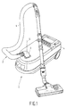
- the vacuum cleaner 1 shown in Fig. 1 is based on a commercially available vacuum cleaner Philips TC 898, but equipped with a vacuum-cleaner-hose assembly 2 in accordance with the invention, which comprises a hose 6 and a modified swivel coupling 3.
- the housing 4 of the vacuum cleaner has been modified accordingly.
- the vacuum-cleaner-hose assembly 2 projects radially relative to an imaginary axis 5 about which the swivel coupling can swivel. As is known per se, this results in a high maneuverability of the suction hose 6.
- bending of the suction hose 6 during use is limited owing to the swivel capability of the swivel coupling 3 and the angle at which the hose 6 extends relative to the swivel axis.
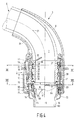
- the vacuum-cleaner-hose assembly 2 comprises a vacuum-cleaner hose 6 and a swivel coupling 3 for coupling the vacuum-cleaner hose 6 to the housing 4 of a vacuum cleaner so as to allow swivelling about a swivel axis 5, the vaccum-cleaner hose 6 enclosing an angle relative to the swivel axis 5 at an end of the swivel coupling 3 remote from the housing 4. Air and dust carried thereby can be drawn into the vacuum cleaner 1 through an air channel 7, which extends via the vacuum-cleaner hose 6 and the coupling 3.
- the shown part of the housing 4 of the vacuum cleaner is constructed as a socket 12 which bounds a recess 13.
- a coupling sleeve 15 is mounted, to which the swivel coupling 3 is connected in a sealed manner in the operating condition shown.
- a seal 22 is interposed between the socket 12 and the coupling sleeve 15.
- the swivel coupling 3 comprises a part which is non-rotatable relative to the housing 4 of the vacuum cleaner in the mounted condition and which comprises an inner bush 16 and an outer bush 17, which are locked relative to one another by means of projections.
- a latching arm 18 is interposed between the inner bush 16 and the outer bush 17 and can be pivoted towards the bushes from a released condition.
- a latching surface 19 of the latching arm 18 engages behind a latching projection 20, which projects from the socket 12.
- the inner bush 16 has a nose 21, which engages against a wall portion of the socket 12, which wall portion extends substantially parallel to the swivel axis 5.
- the swivel coupling 3 comprises a hose guide 8, which surrounds a part of the vacuum-cleaner hose 6 and holds this part of the vacuum-cleaner hose 6 in a curved position.
- the hose guide 8 is rotatably mounted on the outer bush 17 of the swivel coupling 3 and constitutes one of the parts of the swivel coupling 3 which are rotatable relative to the housing 4 of the vacuum cleaner.
- the connection of the vacuum-cleaner hose 6 to the swivel coupling 3 can be arranged closer to that end 9 of the swivel coupling 3 which is to be coupled to the vacuum-cleaner housing 4.
- the swivel coupling 3, in combination or not in combination with an adjoining coupling portion of the vacuum-cleaner hose 6, can thus be of a compact construction, as a result of which the swivel coupling 3, or at least said combination, only projects over a small distance relative to the swivel axis 5 of the swivel coupling 3.
- the vacuum-cleaner hose 6 has an end 10 which is coaxial with the swivel axis 5, which in the construction in accordance with the present example is constituted by an end of a hose spigot 11 which forms part of the hose 6.
- the end 10 of the hose 6 has been formed so as to be coaxial with the swivel axis 5.
- This has the advantage that this end can also serve as an end of the rotatable coupling part of the swivel coupling.
- This in its turn, has the advantage that the connection of the hose 6 to the swivel coupling 3 also forms the connection of the rotatable portion of the swivel coupling 3 to the fixed portion of the swivel coupling 3, which saves a joint to be sealed. Even if the swivel coupling is bodily rotatable relative to the housing the joint to be sealed between the hose and the swivel coupling can be dispensed with. In that case a seal between the end of the hose and the inlet of the vacuum cleaner can suffice.
- the swivel coupling 3 in accordance with the present example comprises a hose-side first coupling part formed by the hose guide 8 and the hose 6 and a second coupling part formed by the inner and outer bushes 16, 17, the first coupling part being rotatable relative to the second coupling part about the swivel axis 5 and the second coupling part being adapted to be coupled to a vacuum-cleaner housing 4.
- the swivel coupling 3 is not separated at the location of the joint between parts which are rotatable relative to one another but at the location of parts to be coupled to one another in each time the same position.
- seals between parts which are rotatable relative to one another are not repeatedly exposed to soiling and the risk of damage.
- the seals between parts to be coupled to one another in each time the same position can be of a simple and robust construction and generally do not require lubrication because the only relative movement between the mutually sealed parts occurs during assembling and disassembling of the relevant coupling parts.
- the vacuum-cleaner hose 6 is, moreover, rotatable about its longitudinal axis 23 inside the hose guide 8.
- the vacuum-cleaner hose 6 can rotate in the hose guide 8 like a flexible shaft. This has the advantage that torsional stresses in the hose 6 are avoided and that the hose 6 can readily adjust to the movements desired during use.
- the rotatability of the hose 6 is obtained without an additional rotary joint to be sealed in that the end 10 of the hose 6 also forms the end to be sealed of the rotatable coupling part. No sealing is required between the hose guide 8, which is rotatable independently of the rotation of the hose 6 about its longitudinal axis 23 and the fixed coupling part, because this rotatable joint is situated outside the hose 6.
- the vacuum-cleaner hose 6 comprises a flexible portion 24 and the hose spigot 11 adjoining the flexible portion at the side of the swivel coupling, and the joint between the flexible portion 23 of the hose 6 and the hose spigot 11 is oriented coaxially with the swivel axis 5, a uniform rotatability of the vacuum-cleaner hose 6 about its longitudinal axis 23 is obtained over one full revolution.
- the hose portion would adjoin the hose spigot at an angle relative to the swivel axis, the hose would each time tend to resume a certain preferential position.
- the hose is then bent less intensively during use than when it is rotatable with a uniform resistance over one full revolution inside the hose guide 8.
- the flexible portion 24 of the vacuum-cleaner hose 6 has been provided with a bundle of electrical conductors, represented diagrammatically at 25.
- the hose spigot 11 which directly adjoins the flexible portion 24 at the side of the swivel coupling 3 has been provided with slip rings 26 connected to the electrical conductors.
- the electrical conductors are arranged as separate conductors 30 in the hose spigot 11. This yields a very efficient construction, in which the hose spigot 11 of the vacuum-cleaner hose 6 also serves as a support for the slip rings 26 and which allows then use of very short conductors between the flexible portion 24 of the hose 6 and the slip rings 26.
- no ducts or recesses are needed for conductors between the vacuum-cleaner hose and the slip rings.
- the same advantages can be obtained when the hose spigot is provided with wiper contacts instead of slip rings.
- the number of slip rings or wiper contacts obviously depends on the envisaged use. If the swivel coupling has been made of a conductive material one slip ring would be adequate in certain cases, the ground connection being formed then by the body of the swivel coupling. However, generally the swivel coupling will have been made of a plastics, so that also a slip ring for at least one ground connection will be required.
- the hose spigot 11 forms part of the hose-side first coupling part.
- the second coupling part further comprises wiper contacts and conductors connected to these contacts.
- Fig. 4 shows one of these wiper contacts 27 and one of these conductors 28.
- Fig. 6 shows only one conductor 28 and one wiper contact 27.
- a further advantage of a second coupling part which in its coupled condition is coupled to the vacuum cleaner in a fixed non-rotatable position, is that for the electrical connection between the swivel coupling 3 and the vacuum-cleaner housing 4 contact pins and contact springs can be used and no slip rings and wiper contacts are necessary, which are more difficult to shield in the uncoupled condition and, consequently, for safety reasons are generally less suitable for transferring mains voltage.
- the contact pins and contact springs of the electrical coupling between the second coupling part and the vacuum cleaner occupy considerably less space than disconnectable slip rings and wiper contacts and are less susceptible to damage and soiling.
- a further advantage of the presence of a second coupling part to be coupled to the vacuum cleaner in a fixed position is that the swivel coupling can be coupled simply because the second coupling part should always be inserted in the same position.
- connection between contact pins 29 of the second coupling part and the slip rings 26 of the first coupling part is obtained in a particularly simple manner in that the contact pins 29 each have an arm 28 which extends up to a location opposite a contact face of the slip rings 26.
- the connection between the contact pins 29 and the slip rings 26 can be obtained very simply.
- connection between the arms 28 of the contact pins 29 and the slip rings 26 is obtained in a very simple manner in that the wiper contacts 27 each project from the conductive arms 28, which are directed transversely to the slip rings 26, towards the relevant slip ring 26.
- the wiper contacts may be constructed as arm portions which project towards the relevant slip rings and which extend along the slip rings.
- a preferred construction is shown in Figures 4 and 6, where the wiper contacts 27 have each been arranged on one of said arms 28 in a position corresponding to the position of the respective slip ring 26, the arms 28 being identical to one another.
- each arm 28 can be brought into contact with a given slip ring 26 by means of a limited variety of parts.
- the arms 28 take the form of extensions of the contact pins 29, the desired connection between a respective arm which extends transversely to the slip ring and a given slip ring can also be obtained if the arms do not form extensions of a contact pin or contact spring but have been connected to further conductors in another manner.
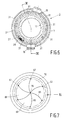
- the slip rings 26 and the contact pins have each been mounted in a recess at a corresponding mounting position. As is shown clearly in Fig. 6, eight positions 31 have been provided for contact pins 29 or at least the arm-shaped extensions 28 of these pins. As is apparent particularly from Fig. 4, the hose spigot 11 has been provided with four recesses for slip rings 26.
- the number of mounting positions 31 adapted to receive contact pins 29 is larger than the number of mounting positions for slip rings 26, it is possible to reserve for each position of a contact pin a specific vacuum-cleaner-hose function, such as remote suction-power control, or the power supply for driving brushes in the vacuum-cleaner nozzle. Since a give position has been provided for each function, a certain vacuum-cleaner-hose assembly, in versions which differ only as regards their electrical configuration, can be used in conjunction with vacuum cleaners having provisions for different vacuum-cleaner-hose functions, without damage or hazardous situations arising if inadvertently a vacuum-cleaner-hose assembly adapted to cooperate with a given type of vacuum cleaner is coupled to another type of vacuum cleaner.
- the vacuum cleaner is adapted to perform a given function but the vacuum-cleaner-hose assembly coupled to it is not adapted to perform this function, damage and hazardous situations are precluded in that the vacuum-cleaner-hose assembly has not been provided with a contact pin or contact pins at the position or the positions reserved for the relevant function and, as a result, simply no contact is made with the contact springs of the vacuum cleaner at the positions corresponding to this function. If the vacuum cleaner is not adapted to perform a given vacuum-cleaner-hose function whereas the coupled vacuum-cleaner-hose assembly is adapted to perform this function, damage and hazardous situations are precluded because in this case the relevant contact pin of the vacuum-cleaner-hose assembly cannot become live.
- connection points of the vacuum cleaner to which mains voltage is applied are, for example, connection points connected to the power supply for an electric motor for driving brushes in the nozzle.
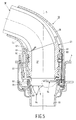
- Figures 3 and 5 show the swivel coupling 33 and an adjoining portion of vacuum-cleaner hose 36 of a vacuum-cleaner-hose assembly in another embodiment of the invention. These Figures further show a part of the vacuum-cleaner housing 4.
- the vacuum-cleaner hose 36 comprises inter alia a flexible portion 54 and a hose spigot 41 connected to the flexible portion 54 at the side of the swivel coupling 33.
- the air channel 37 for the intake of air takes the form of a bend in the swivel coupling 33, which extends partly in the hose spigot 41 and partly in the flexible portion 54 of the vacuum-cleaner hose 36, which portion is held in a curved condition.
- the air channel 37 can already deflect in the hose spigot 41 relative to the part of the air channel 37 which is coaxial with the swivel axis 5, which results in an even more compact swivel coupling 33.
- the vacuum-cleaner-hose assembly shown in Figures 3 and 5 has been simplified further as compared with the vacuum-cleaner-hose assembly described hereinbefore, in that the coupling part which is non-rotatable relative to the housing 4 in the coupled condition does not comprise an inner bush 16 and an outer bush 17 but comprises a single bush 46.
- the hose guide 38 has a circumferential rim 60 which engages behind projections 61 of the bush 46. Said projections 61 of the bush 46 have tapered run-on surfaces, so that the hose guide 38 can readily be snapped onto the bush 46.
- the hose guide 38 In the mounted condition the hose guide 38 is rotatable relative to the bush 46 and also holds the hose spigot 41 in the correct position in the bush 46 by means of a circumferential rim 62 which engages with the hose spigot 41. Since the hose spigot 41 extends into a part of the hose guide 38 which is curved relative to the swivel axis 5, the hose spigot 41, when possible play is ignored, can only be swivelled together with the hose guide relative to the bush 46.
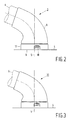
- Figure 7 diagrammatically shows the inlet duct 63 in the vacuum cleaner in plan view.
- Figures 4 and 5 show the inlet duct 63 in sectional view in combination with vacuum-cleaner-hose assemblies described hereinbefore and coupled thereto.
- a sealing diaphragm 64 arranged in the inlet duct 63 serves for at least for the greater part closing the inlet duct 63 when the vacuum-cleaner-hose assembly has been removed from the vacuum cleaner and for opening the inlet duct 63 when the vacuum-cleaner-hose assembly has been coupled to the vacuum-cleaner housing 4.
- Figures 4 and 5 have inset portions which each show a part of the inlet duct 63 in which the sealing diaphragm 64 is disposed when the vacuum-cleaner-hose assembly has been removed and a part of the sealing diaphragm 64 is consequently in a closed position.
- Fig. 7 also shows the sealing diaphragm 64 in the closed position.
- Figures 3 and 4 also show a part of the sealing diaphragm 64 in the open position.
- the sealing diaphragm 64 has cuts 65 which, when the vacuum-cleaner-hose assembly has been removed, each extend from a central area 66 of the diaphragm to a point near the wall of the inlet duct 63 and whose outer ends 67 are equispaced in the circumferential direction.
- the vacuum-cleaner-hose assembly has a tubular end portion 9, which in the coupled condition passes through the sealing diaphragm 64 and folds the segments 69 defined by the cuts 65 in the direction of flow through the inlet duct 63.
- a part 68 of the tubular end portion 9 which engages with the sealing diaphragm 64 in the coupled condition has such a cross-section that in the coupled condition a circumferentially uninterrupted part 70 of the sealing diaphragm 64, which part 70 adjoins the area defined by the outer ends 67 of the cuts 65, is extended in a circumferential direction and is in sealing engagement with the tubular end portion 9 of the vacuum-cleaner-hose assembly.
- a further advantage of the present seal is that a sealing element can be used of which, viewed in the flow direction, one side is identical to the other side, so that it is irrelevant which side of the sealing element faces the interior of the housing 4 during assembly.
- sealing diaphragm as described hereinbefore can also be achieved when the sealing element is used in conjunction with other vacuum-cleaner-hose assemblies than described hereinbefore, for example in combination with vacuum-cleaner-hose assemblies comprising conventional swivel couplings which may be rotatable bodily relative to the vacuum cleaner, which may comprise a part which is rotatable relative to the vacuum cleaner and a part which is non-rotatable relative to the vacuum cleaner, or which may be adapted for non-rotatable mounting on a swiveling part of the vacuum cleaner.
- the tubular end portion which need not be circular, has such a shape and size that in the coupled condition an uninterrupted slightly extended part of the diaphragm is in engagement with the tubular end portion.
- the tubular end portion 9 has a tapered exterior, as a result of which the frictional resistance between the tubular end portion 9 and the segments 69 which spring back is low when the vacuum-cleaner-hose assembly is removed.
- Uncoupling of the vacuum-cleaner-hose assembly is further facilitated by the fact that the tubular end portion 9, in the coupled condition of the vacuum-cleaner-hose assembly, extends less far into the inlet duct 63 than the folded diaphragm segments 69 defined by the cuts 65. For a satisfactory folding of the segments 69 when the tubular end portion 9 is passed through the diaphragm 64 it appears not to be necessary for the tubular end portion 9 to extend up to the free ends of the folded segments 69.
Abstract
Description
Claims (16)
- A vacuum-cleaner-hose assembly comprising a vacuum-cleaner hose (6, 36) and a swivel coupling (3, 33) for coupling the vacuum-cleaner hose to a housing (4) of a vacuum cleaner so as to allow swivelling about a swivel axis (5), the longitudinal axis of the hose (6, 36) at the swivel coupling (3, 33) end remote from the housing (4) forming an angle with respect to the swivel axis (5), an air channel (7, 37) extending through the vacuum-cleaner hose (6, 36) and the swivel coupling (3, 33), characterized in that the swivel coupling (3, 33) comprises a hose guide (8, 38) which surrounds a flexible portion (24, 54) of the vacuum-cleaner hose (6, 36) and holds said portion of the vacuum-cleaner hose (6,36) in a curved position.
- A vacuum-cleaner-hose assembly as claimed in Claim 1, the swivel coupling (3, 33) comprising a rotatable coupling part adapted to cooperate with a fixed coupling part, and the vacuum-cleaner hose (6, 36), at the side of said swivel coupling (3, 33), having an end which is coaxial with the swivel axis (5).
- A vacuum-cleaner-hose assembly as claimed in Claim 1 or 2, the vacuum-cleaner hose (6) being rotatable about its longitudinal axis in the hose guide (8).
- A vacuum-cleaner-hose assembly as claimed in Claim 3, the vacuum-cleaner hose (6) comprising a flexible portion (24) and a hose spigot (11) adjoining the flexible portion (24) at the side of the swivel coupling (3), and the joint between the flexible portion (24) of the vacuum-cleaner hose (6, 36) and the hose spigot (11) being oriented coaxially with the swivel axis (5).
- A vacuum-cleaner-hose assembly as claimed in Claim 1 or 2, the vacuum-cleaner hose (36) comprising a flexible portion (54) and a hose spigot (41) adjoining the flexible portion (54) at the side of the swivel coupling (33), and the air channel (37) in the swivel coupling (33) taking the form of a bend, which extends partly in the hose spigot (41) and partly in said flexible portion (54) of the vacuum-cleaner hose (36), which portion is held in a curved condition.
- A vacuum-cleaner-hose assembly as claimed in any one of the preceding Claims, the swivel coupling (3, 33) comprising a hose-side first coupling part and a second coupling part, the first coupling part being rotatable relative to the second coupling part about the swivel axis (5) and the second coupling part being adapted to be coupled to a vacuum cleaner (4).
- A vacuum-cleaner-hose assembly as claimed in any one of the preceding Claims, the vacuum-cleaner hose (6, 36) comprising: a flexible portion (24, 54) provided with at least one electrical conductor (25) and a hose spigot (11, 41) adjoining the flexible portion (24, 54) at the side of the swivel coupling (3, 33) and provided with at least one slip ring (26) or wiper contact connected to the electrical conductor (25).
- A vacuum-cleaner-hose assembly as claimed in Claims 6 and 7, said hose spigot (11, 41) forming part of said hose-side first coupling part, and said second coupling part being provided with at least one wiper contact (27) or slip ring and at least one conductor (30) connected thereto.
- A vacuum-cleaner-hose assembly as claimed in Claim 6, the vacuum-cleaner hose (6, 36) being provided with at least one electrical conductor (25), said first coupling part being provided with at least one slip ring (26), and said second coupling part being provided with at least one wiper contact (27), which cooperates with said slip ring (26), and at least one contact pin (29) or contact spring for cooperation with at least one contact spring or contact pin, respectively, of a vacuum cleaner (4), and the or each contact pin (29) or contact spring of said second coupling part having an arm (28) which extends up to a location opposite a contact face of the slip ring or at least one of the slip rings (26).
- A vacuum-cleaner-hose assembly as claimed in Claim 6 or 9, the vacuum-cleaner hose (6, 36) being provided with at least one electrical conductor (25), said first and said second coupling part being electrically coupled by at least one slip ring (26) and a wiper contact (27) which cooperates with said slip ring, said second coupling part being provided with at least one contact pin (29) or contact spring for cooperation with at least one contact spring or contact pin, of a vacuum cleaner (4), the or each slip ring (26) and the or each contact pin (29) or contact spring being mounted in a corresponding mounting position, and the number of mounting positions adapted to receive a contact pin (29) or contact spring, as mentioned, being greater than the number of mounting positions for slip rings (26).
- A vacuum-cleaner-hose assembly as claimed in any one of the preceding Claims, the vacuum-cleaner hose (6, 36) being provided with electrical conductors (25), the swivel coupling (3, 33) comprising a hose-side first coupling part and a second coupling part, the first coupling part being rotatable relative to the second coupling part about the swivel axis (5), the swivel coupling (3, 33) being provided with cooperating wiper contacts (27), which are connected to the electrical conductor (25), and mutually coaxial slip rings (26), the wiper contacts (27) each projecting from arms (28) of a conductive material towards the respective one of the slip rings (26), which arms extend transversely to the slip rings (26) and along these slip rings (26).
- A vacuum-cleaner-hose assembly as claimed in Claim 10, the wiper contacts (27) each being arranged on one of said arms (28) in a position corresponding to the position of the respective slip ring (26) and said arms (28) being identical to one another.
- A vacuum cleaner comprising a housing and a vacuum-cleaner-hose assembly comprising a vacuum-cleaner hose (6, 36) and a coupling (3, 33) by means of which the vacuum cleaner hose can be coupled to the housing (4) of the vacuum cleaner, and an air channel (7, 37) extending through the vacuum-cleaner hose (6, 36) and the coupling (3, 33), characterized in that the vacuum-cleaner-hose assembly is a vacuum cleaner-hose assembly as claimed in any one of the preceding Claims.
- A vacuum cleaner as claimed in Claim 13, comprising an inlet duct (63) for the connection of the vacuum-cleaner-hose assembly (2) and a sealing diaphragm (64) in the inlet duct (63) for at least substantially closing the inlet duct (63) when the vacuum-cleaner-hose assembly of the vacuum cleaner (4) is in the uncoupled condition and for opening the inlet duct (63) when the vacuum-cleaner-hose assembly has been coupled to the vacuum cleaner (4), the sealing diaphragm (64) having cuts (65) which, when the vacuum-cleaner-hose assembly has been uncoupled, each extend from a central area (66) of the diaphragm (64) to a point near the wall of the inlet duct (63) and whose outer ends (67) are equispaced in the circumferential direction, the vacuum-cleaner-hose assembly having a tubular end portion (9), which in the coupled condition passes through the sealing diaphragm (64) and folds the segments (69) defined by the cuts (65) in the direction of flow through the inlet duct (63), and a part (68) of the tubular end portion (9), which part engages with the sealing diaphragm (64) in the coupled condition, having such a cross-section that in the coupled condition a circumferentially uninterrupted part (70) of the sealing diaphragm (64), which part (70) adjoins the area defined by the outer ends (67) of the cuts (65), is extended in a circumferential direction and is in sealing engagement with the tubular end portion (9) of the vacuum-cleaner-hose assembly (2).
- A vacuum cleaner as claimed in Claim 14, the tubular end portion (9) having a tapered exterior.
- A vacuum cleaner as claimed in Claim 14 or 15, the tubular end portion (9), in the coupled condition of the vacuum-cleaner-hose assembly (2), extending less far into the inlet duct (63) than the folded segments (69) of the diaphragm (64) which are defined by the cuts.
Priority Applications (1)
| Application Number | Priority Date | Filing Date | Title |
|---|---|---|---|
| EP96932787A EP0804119B1 (en) | 1995-10-30 | 1996-10-23 | Vacuum-cleaner-hose assembly having a swivel bend and vacuum cleaner comprising such assembly |
Applications Claiming Priority (4)
| Application Number | Priority Date | Filing Date | Title |
|---|---|---|---|
| EP95202925 | 1995-10-30 | ||
| EP95202925 | 1995-10-30 | ||
| PCT/IB1996/001136 WO1997016111A1 (en) | 1995-10-30 | 1996-10-23 | Vacuum-cleaner-hose assembly having a swivel bend and vacuum cleaner comprising such assembly |
| EP96932787A EP0804119B1 (en) | 1995-10-30 | 1996-10-23 | Vacuum-cleaner-hose assembly having a swivel bend and vacuum cleaner comprising such assembly |
Publications (2)
| Publication Number | Publication Date |
|---|---|
| EP0804119A1 EP0804119A1 (en) | 1997-11-05 |
| EP0804119B1 true EP0804119B1 (en) | 2001-04-04 |
Family
ID=8220778
Family Applications (1)
| Application Number | Title | Priority Date | Filing Date |
|---|---|---|---|
| EP96932787A Expired - Lifetime EP0804119B1 (en) | 1995-10-30 | 1996-10-23 | Vacuum-cleaner-hose assembly having a swivel bend and vacuum cleaner comprising such assembly |
Country Status (7)
| Country | Link |
|---|---|
| US (1) | US5755578A (en) |
| EP (1) | EP0804119B1 (en) |
| JP (1) | JPH10512180A (en) |
| KR (1) | KR100449933B1 (en) |
| CN (1) | CN1124821C (en) |
| DE (1) | DE69612371T2 (en) |
| WO (1) | WO1997016111A1 (en) |
Families Citing this family (71)
| Publication number | Priority date | Publication date | Assignee | Title |
|---|---|---|---|---|
| DE10131175B4 (en) * | 2001-06-29 | 2008-06-19 | BSH Bosch und Siemens Hausgeräte GmbH | vacuum cleaner |
| EP1011458A2 (en) | 1996-11-08 | 2000-06-28 | Russell A. Houser | Percutaneous bypass graft and securing system |
| IT250179Y1 (en) * | 2000-07-28 | 2003-07-24 | Tamborini Giancarlo | HANDLE STRUCTURE FOR VACUUM CLEANERS |
| DE20206730U1 (en) * | 2002-04-26 | 2002-10-10 | Truplast Kunststofftechnik | Coupling sleeve for connecting a suction hose to a housing |
| JP2004159835A (en) * | 2002-11-12 | 2004-06-10 | Izumi Products Co | Vacuum cleaner |
| KR100485357B1 (en) * | 2002-12-10 | 2005-04-27 | 주식회사 대우일렉트로닉스 | Adapter of cleaner |
| US7226302B2 (en) * | 2003-09-22 | 2007-06-05 | Scotech Systems Inc. | Vacuum cleaner current-carrying hose connection system |
| US20050109375A1 (en) * | 2003-11-26 | 2005-05-26 | Scott Peterson | Vent cleaning system |
| US8783257B2 (en) | 2004-02-23 | 2014-07-22 | Fisher & Paykel Healthcare Limited | Breathing assistance apparatus |
| WO2005094928A1 (en) | 2004-04-02 | 2005-10-13 | Fisher & Paykel Healthcare Limited | Breathing assistance apparatus |
| US9072852B2 (en) | 2004-04-02 | 2015-07-07 | Fisher & Paykel Healthcare Limited | Breathing assistance apparatus |
| US7987552B2 (en) * | 2004-11-17 | 2011-08-02 | Techtronic Floor Care Technology Limited | Floor care appliance with a plurality of cleaning modes |
| US7275279B2 (en) * | 2005-02-10 | 2007-10-02 | Nationwide Sales & Service, Inc. | Vacuum cleaner wand adapters and handle assemblies including the same |
| DE102005045543A1 (en) * | 2005-09-23 | 2007-03-29 | Vorwerk & Co. Interholding Gmbh | Canister |
| US7774894B2 (en) * | 2005-10-11 | 2010-08-17 | Kimberly-Clark Worldwide, Inc. | Micro powered floor cleaning device |
| CA2890556C (en) | 2006-07-14 | 2018-05-01 | Fisher & Paykel Healthcare Limited | Breathing assistance apparatus |
| US7537457B2 (en) * | 2006-10-03 | 2009-05-26 | Irwin Rashkover | Electrical hose swivel connector |
| US10258757B2 (en) | 2008-05-12 | 2019-04-16 | Fisher & Paykel Healthcare Limited | Patient interface and aspects thereof |
| US10792451B2 (en) | 2008-05-12 | 2020-10-06 | Fisher & Paykel Healthcare Limited | Patient interface and aspects thereof |
| US8534301B2 (en) | 2008-06-02 | 2013-09-17 | Innovation Direct Llc | Steam mop |
| US11660413B2 (en) | 2008-07-18 | 2023-05-30 | Fisher & Paykel Healthcare Limited | Breathing assistance apparatus |
| US8653942B2 (en) | 2008-08-20 | 2014-02-18 | John Gibson Enterprises, Inc. | Portable biometric lighter |
| WO2010041966A1 (en) | 2008-10-10 | 2010-04-15 | Fisher & Paykel Healthcare Limited | Nasal pillows for a patient interface |
| US10137271B2 (en) | 2009-11-18 | 2018-11-27 | Fisher & Paykel Healthcare Limited | Nasal interface |
| GB2534305A (en) | 2009-12-23 | 2016-07-20 | Fisher & Paykel Healthcare Ltd | Patient interface and headgear |
| US20110174935A1 (en) * | 2010-01-21 | 2011-07-21 | Chalice Bingham | Swivel-coupling hanger assembly |
| DE102010027090B3 (en) * | 2010-07-13 | 2011-11-17 | Roxxan Gmbh | Vacuum cleaner suction pipe, has sealing ring forming sealing bead at front region of sleeve portion, where sealing bead rests at inner surface of pipe and at outer surface of connection component in complete gap-sealing manner |
| JP5546980B2 (en) * | 2010-07-16 | 2014-07-09 | 株式会社東芝 | Vacuum cleaner hose and vacuum cleaner |
| DE102010039284B4 (en) | 2010-08-12 | 2012-06-14 | BSH Bosch und Siemens Hausgeräte GmbH | Connecting piece with locking tab |
| US9561338B2 (en) | 2010-10-08 | 2017-02-07 | Fisher & Paykel Healthcare Limited | Breathing assistance apparatus |
| JP2012179269A (en) * | 2011-03-02 | 2012-09-20 | Panasonic Corp | Drum washing machine |
| DE102011007202A1 (en) * | 2011-04-12 | 2012-10-18 | BSH Bosch und Siemens Hausgeräte GmbH | Connector for a vacuum cleaner hose |
| US10603456B2 (en) | 2011-04-15 | 2020-03-31 | Fisher & Paykel Healthcare Limited | Interface comprising a nasal sealing portion |
| DE112012007300B4 (en) | 2011-04-15 | 2024-04-25 | Fisher & Paykel Healthcare Ltd. | Interface with a movable nose bridge |
| US9131815B2 (en) * | 2011-11-07 | 2015-09-15 | Mark Genoa | Vacuum cleaner hose assembly connector |
| CN107626023B (en) | 2012-08-08 | 2021-03-02 | 费雪派克医疗保健有限公司 | Interface assembly for use in providing respiratory therapy |
| GB2519251B (en) * | 2012-08-08 | 2018-04-04 | Fisher & Paykel Healthcare Ltd | Breathing tube assemblies with adjustable elbow |
| EP2892596B1 (en) | 2012-09-04 | 2023-07-26 | Fisher&Paykel Healthcare Limited | Valsalva mask |
| GB2528435A (en) * | 2014-07-09 | 2016-01-27 | Techtronic Ind Co Ltd | Surface cleaning apparatus |
| GB2587307B (en) | 2014-08-25 | 2021-10-27 | Fisher & Paykel Healthcare Ltd | Respiratory mask and related portions, components or sub-assemblies |
| TW202332392A (en) | 2014-09-16 | 2023-08-16 | 紐西蘭商費雪 & 佩凱爾關心健康有限公司 | Intramold headgear |
| US10646680B2 (en) | 2014-09-19 | 2020-05-12 | Fisher & Paykel Healthcare Limited | Headgear assemblies and interface assemblies with headgear |
| US20160279759A1 (en) * | 2015-03-24 | 2016-09-29 | Full Circle International, Inc. | Hand sander vacuum adapter |
| WO2017150862A1 (en) | 2016-02-29 | 2017-09-08 | 엘지전자 주식회사 | Vacuum cleaner |
| KR101903257B1 (en) | 2016-03-25 | 2018-11-22 | 엘지전자 주식회사 | Vacuum cleaner |
| TWI643597B (en) | 2016-02-29 | 2018-12-11 | Lg電子股份有限公司 | Vacuum cleaner |
| DE202017000984U1 (en) | 2016-02-29 | 2017-05-29 | Lg Electronics Inc. | vacuum cleaner |
| DE202017000985U1 (en) | 2016-02-29 | 2017-05-29 | Lg Electronics Inc. | vacuum cleaner |
| AU2017227412B2 (en) | 2016-02-29 | 2020-01-23 | Lg Electronics Inc. | Vacuum cleaner |
| TWI664944B (en) | 2016-02-29 | 2019-07-11 | Lg電子股份有限公司 | Vacuum cleaner |
| WO2017150816A1 (en) | 2016-02-29 | 2017-09-08 | 엘지전자 주식회사 | Vacuum cleaner |
| TWI641353B (en) | 2016-02-29 | 2018-11-21 | Lg電子股份有限公司 | Vacuum cleaner |
| WO2017150874A1 (en) | 2016-02-29 | 2017-09-08 | 엘지전자 주식회사 | Vacuum cleaner |
| TWI636758B (en) | 2016-02-29 | 2018-10-01 | Lg電子股份有限公司 | Vacuum cleaner |
| TWI653962B (en) | 2016-02-29 | 2019-03-21 | Lg電子股份有限公司 | Vacuum cleaner |
| TWI637718B (en) | 2016-02-29 | 2018-10-11 | Lg電子股份有限公司 | Vacuum cleaner |
| TWI664943B (en) | 2016-02-29 | 2019-07-11 | Lg電子股份有限公司 | Vacuum cleaner |
| TWI643596B (en) | 2016-02-29 | 2018-12-11 | Lg電子股份有限公司 | Vacuum cleaner |
| AU2017234346B2 (en) | 2016-03-16 | 2022-06-30 | Fisher & Paykel Healthcare Limited | Directional lock for interface headgear arrangement |
| CN115212416A (en) | 2016-03-16 | 2022-10-21 | 费雪派克医疗保健有限公司 | Bandage subassembly |
| SG11201807697QA (en) | 2016-03-16 | 2018-10-30 | Fisher & Paykel Healthcare Ltd | Intra-mould substrate |
| USD882066S1 (en) | 2016-05-13 | 2020-04-21 | Fisher & Paykel Healthcare Limited | Frame for a breathing mask |
| DE202017002619U1 (en) | 2016-05-20 | 2017-08-04 | Lg Electronics Inc. | vacuum cleaner |
| USD823454S1 (en) | 2017-02-23 | 2018-07-17 | Fisher & Paykel Healthcare Limited | Cushion assembly for breathing mask assembly |
| USD824020S1 (en) | 2017-02-23 | 2018-07-24 | Fisher & Paykel Healthcare Limited | Cushion assembly for breathing mask assembly |
| USD823455S1 (en) | 2017-02-23 | 2018-07-17 | Fisher & Paykel Healthcare Limited | Cushion assembly for breathing mask assembly |
| US10502419B2 (en) | 2017-09-12 | 2019-12-10 | John Gibson Enterprises, Inc. | Portable biometric lighter |
| AU2019235660A1 (en) | 2018-03-16 | 2020-09-24 | Fisher & Paykel Healthcare Limited | Headgear with lock disengagement mechanism |
| KR20200011709A (en) | 2018-07-25 | 2020-02-04 | (주)대한솔루션 | Indicator for years, months and days |
| DE102018120641A1 (en) * | 2018-08-23 | 2020-02-27 | Vorwerk & Co. Interholding Gmbh | System, suction pipe and method for unlocking a connection between a vacuum cleaner main body and a suction nozzle or for unlocking a connection between a suction pipe and a suction nozzle |
| DE102019135006A1 (en) * | 2019-12-18 | 2021-06-24 | GNS-KV GmbH | vehicle |
Family Cites Families (5)
| Publication number | Priority date | Publication date | Assignee | Title |
|---|---|---|---|---|
| DE895682C (en) * | 1951-06-27 | 1953-11-05 | Neue Argus Ges M B H | Device for supporting a flexible hose in a curve against kinking |
| US4557535A (en) * | 1984-09-17 | 1985-12-10 | Whirlpool Corporation | Electrical hose swivel connector for canister vacuum cleaner |
| US4550958A (en) * | 1984-09-17 | 1985-11-05 | Whirlpool Corporation | Electrical hose swivel connector for canister vacuum cleaner |
| DE8712478U1 (en) * | 1987-09-15 | 1989-01-12 | Siemens Ag, 1000 Berlin Und 8000 Muenchen, De | |
| US5389004A (en) * | 1993-04-23 | 1995-02-14 | Electrolux Corporation | Handle and wand system for vacuum cleaner |
-
1996
- 1996-10-23 WO PCT/IB1996/001136 patent/WO1997016111A1/en active IP Right Grant
- 1996-10-23 CN CN96192038A patent/CN1124821C/en not_active Expired - Fee Related
- 1996-10-23 EP EP96932787A patent/EP0804119B1/en not_active Expired - Lifetime
- 1996-10-23 KR KR1019970704432A patent/KR100449933B1/en not_active IP Right Cessation
- 1996-10-23 DE DE69612371T patent/DE69612371T2/en not_active Expired - Fee Related
- 1996-10-23 JP JP9517182A patent/JPH10512180A/en not_active Abandoned
- 1996-10-30 US US08/739,772 patent/US5755578A/en not_active Expired - Fee Related
Also Published As
| Publication number | Publication date |
|---|---|
| DE69612371D1 (en) | 2001-05-10 |
| KR100449933B1 (en) | 2004-12-16 |
| CN1175891A (en) | 1998-03-11 |
| KR980700817A (en) | 1998-04-30 |
| DE69612371T2 (en) | 2001-10-18 |
| JPH10512180A (en) | 1998-11-24 |
| CN1124821C (en) | 2003-10-22 |
| WO1997016111A1 (en) | 1997-05-09 |
| US5755578A (en) | 1998-05-26 |
| EP0804119A1 (en) | 1997-11-05 |
Similar Documents
| Publication | Publication Date | Title |
|---|---|---|
| EP0804119B1 (en) | Vacuum-cleaner-hose assembly having a swivel bend and vacuum cleaner comprising such assembly | |
| US4980945A (en) | Safety interlock device for a vacuum cleaner | |
| US5031266A (en) | Vacuum cleaner wand seal | |
| US4345805A (en) | Self-sealing vacuum hose swivel fitting | |
| US4550958A (en) | Electrical hose swivel connector for canister vacuum cleaner | |
| JP4544536B2 (en) | Transmission vacuum cleaner hose connection system | |
| EP1251765B1 (en) | Steering assembly particulary for domestic and/or industrial cleaning machines | |
| CN109845045B (en) | Electrical connector with plug latch assembly | |
| US4277640A (en) | Electric current-carrying hose assembly having end fittings enclosing an electrical switch and/or a circuit-breaking device | |
| EP0328494A1 (en) | Coupling device | |
| EP3855994B1 (en) | Connector assemblies and associated methods | |
| US5983444A (en) | Vacuum cleaner with a motor casing | |
| US2103050A (en) | Dusting tool for suction cleaners | |
| US4940415A (en) | Key system for vacuum cleaner hose connection | |
| JP2589338B2 (en) | Vacuum cleaner suction pipe | |
| CA1293346C (en) | Nozzle with improved coupling for a vacuum device | |
| JPH09512197A (en) | Joint having two relative rotatable and electrically connectable joint members and vacuum cleaner provided with such joint | |
| US4550957A (en) | Electrical hose swivel connector for canister vacuum cleaner | |
| EP0136894A2 (en) | Anti-Disengagement device | |
| US3002216A (en) | Electrical control for suction cleaners | |
| JPH0795993B2 (en) | Vacuum cleaner connection tube | |
| JPH0793916B2 (en) | Vacuum cleaner connection tube | |
| CN209285373U (en) | The component of hose for household electrical appliance | |
| KR200151838Y1 (en) | Mounting structure for vacuum cleaner | |
| JPS6053621B2 (en) | Vacuum cleaner suction force adjustment device |
Legal Events
| Date | Code | Title | Description |
|---|---|---|---|
| PUAI | Public reference made under article 153(3) epc to a published international application that has entered the european phase |
Free format text: ORIGINAL CODE: 0009012 |
|
| AK | Designated contracting states |
Kind code of ref document: A1 Designated state(s): DE FR GB IT NL SE |
|
| 17P | Request for examination filed |
Effective date: 19971110 |
|
| 17Q | First examination report despatched |
Effective date: 19990609 |
|
| GRAG | Despatch of communication of intention to grant |
Free format text: ORIGINAL CODE: EPIDOS AGRA |
|
| GRAG | Despatch of communication of intention to grant |
Free format text: ORIGINAL CODE: EPIDOS AGRA |
|
| GRAH | Despatch of communication of intention to grant a patent |
Free format text: ORIGINAL CODE: EPIDOS IGRA |
|
| GRAH | Despatch of communication of intention to grant a patent |
Free format text: ORIGINAL CODE: EPIDOS IGRA |
|
| GRAA | (expected) grant |
Free format text: ORIGINAL CODE: 0009210 |
|
| AK | Designated contracting states |
Kind code of ref document: B1 Designated state(s): DE FR GB IT NL SE |
|
| PG25 | Lapsed in a contracting state [announced via postgrant information from national office to epo] |
Ref country code: NL Free format text: LAPSE BECAUSE OF FAILURE TO SUBMIT A TRANSLATION OF THE DESCRIPTION OR TO PAY THE FEE WITHIN THE PRESCRIBED TIME-LIMIT Effective date: 20010404 Ref country code: IT Free format text: LAPSE BECAUSE OF FAILURE TO SUBMIT A TRANSLATION OF THE DESCRIPTION OR TO PAY THE FEE WITHIN THE PRESCRIBED TIME-LIMIT;WARNING: LAPSES OF ITALIAN PATENTS WITH EFFECTIVE DATE BEFORE 2007 MAY HAVE OCCURRED AT ANY TIME BEFORE 2007. THE CORRECT EFFECTIVE DATE MAY BE DIFFERENT FROM THE ONE RECORDED. Effective date: 20010404 |
|
| REF | Corresponds to: |
Ref document number: 69612371 Country of ref document: DE Date of ref document: 20010510 |
|
| ET | Fr: translation filed | ||
| NLV1 | Nl: lapsed or annulled due to failure to fulfill the requirements of art. 29p and 29m of the patents act | ||
| REG | Reference to a national code |
Ref country code: GB Ref legal event code: IF02 |
|
| PLBE | No opposition filed within time limit |
Free format text: ORIGINAL CODE: 0009261 |
|
| STAA | Information on the status of an ep patent application or granted ep patent |
Free format text: STATUS: NO OPPOSITION FILED WITHIN TIME LIMIT |
|
| 26N | No opposition filed | ||
| PGFP | Annual fee paid to national office [announced via postgrant information from national office to epo] |
Ref country code: DE Payment date: 20031215 Year of fee payment: 8 |
|
| PGFP | Annual fee paid to national office [announced via postgrant information from national office to epo] |
Ref country code: SE Payment date: 20041026 Year of fee payment: 9 |
|
| PGFP | Annual fee paid to national office [announced via postgrant information from national office to epo] |
Ref country code: FR Payment date: 20041027 Year of fee payment: 9 |
|
| PGFP | Annual fee paid to national office [announced via postgrant information from national office to epo] |
Ref country code: GB Payment date: 20041028 Year of fee payment: 9 |
|
| PG25 | Lapsed in a contracting state [announced via postgrant information from national office to epo] |
Ref country code: DE Free format text: LAPSE BECAUSE OF NON-PAYMENT OF DUE FEES Effective date: 20050503 |
|
| PG25 | Lapsed in a contracting state [announced via postgrant information from national office to epo] |
Ref country code: GB Free format text: LAPSE BECAUSE OF NON-PAYMENT OF DUE FEES Effective date: 20051023 |
|
| PG25 | Lapsed in a contracting state [announced via postgrant information from national office to epo] |
Ref country code: SE Free format text: LAPSE BECAUSE OF NON-PAYMENT OF DUE FEES Effective date: 20051024 |
|
| EUG | Se: european patent has lapsed | ||
| GBPC | Gb: european patent ceased through non-payment of renewal fee |
Effective date: 20051023 |
|
| PG25 | Lapsed in a contracting state [announced via postgrant information from national office to epo] |
Ref country code: FR Free format text: LAPSE BECAUSE OF NON-PAYMENT OF DUE FEES Effective date: 20060630 |
|
| REG | Reference to a national code |
Ref country code: FR Ref legal event code: ST Effective date: 20060630 |