EP3880911B1 - Kraftfahrzeug-schliesssystem - Google Patents
Kraftfahrzeug-schliesssystem Download PDFInfo
- Publication number
- EP3880911B1 EP3880911B1 EP19765655.6A EP19765655A EP3880911B1 EP 3880911 B1 EP3880911 B1 EP 3880911B1 EP 19765655 A EP19765655 A EP 19765655A EP 3880911 B1 EP3880911 B1 EP 3880911B1
- Authority
- EP
- European Patent Office
- Prior art keywords
- motor vehicle
- blocking
- locking system
- housing
- locking
- Prior art date
- Legal status (The legal status is an assumption and is not a legal conclusion. Google has not performed a legal analysis and makes no representation as to the accuracy of the status listed.)
- Active
Links
Images


Classifications
-
- E—FIXED CONSTRUCTIONS
- E05—LOCKS; KEYS; WINDOW OR DOOR FITTINGS; SAFES
- E05B—LOCKS; ACCESSORIES THEREFOR; HANDCUFFS
- E05B81/00—Power-actuated vehicle locks
- E05B81/54—Electrical circuits
- E05B81/80—Electrical circuits characterised by the power supply; Emergency power operation
-
- E—FIXED CONSTRUCTIONS
- E05—LOCKS; KEYS; WINDOW OR DOOR FITTINGS; SAFES
- E05B—LOCKS; ACCESSORIES THEREFOR; HANDCUFFS
- E05B79/00—Mounting or connecting vehicle locks or parts thereof
- E05B79/10—Connections between movable lock parts
- E05B79/12—Connections between movable lock parts using connecting rods
-
- E—FIXED CONSTRUCTIONS
- E05—LOCKS; KEYS; WINDOW OR DOOR FITTINGS; SAFES
- E05B—LOCKS; ACCESSORIES THEREFOR; HANDCUFFS
- E05B79/00—Mounting or connecting vehicle locks or parts thereof
- E05B79/10—Connections between movable lock parts
- E05B79/22—Operative connections between handles, sill buttons or lock knobs and the lock unit
-
- E—FIXED CONSTRUCTIONS
- E05—LOCKS; KEYS; WINDOW OR DOOR FITTINGS; SAFES
- E05B—LOCKS; ACCESSORIES THEREFOR; HANDCUFFS
- E05B81/00—Power-actuated vehicle locks
- E05B81/54—Electrical circuits
- E05B81/90—Manual override in case of power failure
-
- B—PERFORMING OPERATIONS; TRANSPORTING
- B60—VEHICLES IN GENERAL
- B60R—VEHICLES, VEHICLE FITTINGS, OR VEHICLE PARTS, NOT OTHERWISE PROVIDED FOR
- B60R25/00—Fittings or systems for preventing or indicating unauthorised use or theft of vehicles
- B60R25/20—Means to switch the anti-theft system on or off
- B60R25/24—Means to switch the anti-theft system on or off using electronic identifiers containing a code not memorised by the user
Definitions
- the invention relates to a motor vehicle locking system for a motor vehicle door or flap with the features specified in the preamble of claim 1.
- a motor vehicle locking system for a motor vehicle door or flap of the type described at the outset is known, for example, which has a motor vehicle lock with a lock housing in which a locking mechanism and unlocking mechanism or locking mechanism for releasing or blocking the locking mechanism, e.g. by an electric motor, is arranged, wherein the locking mechanism is only released or blocked if an authorized user has previously authenticated himself with the main control unit. Authentication takes place by means of a code exchange between the main control unit and an electronic key which is carried by the user.
- the locking mechanism comprises a rotatably mounted rotary latch for closing or opening a motor vehicle door or flap and a pawl provided for actuating the rotary latch, which interacts with the unlocking mechanism or locking mechanism.
- the motor vehicle locking system has a so-called mechanical emergency locking cylinder.
- a mechanical emergency locking cylinder works together with a mechanical emergency key to manually unlock the motor vehicle locking system or to transfer it to the unlocking state by inserting the mechanical emergency key in a known manner into the mechanical emergency locking cylinder and turning it to unlock.
- the locking mechanism is unlocked, the The vehicle door or hatch can be opened using an outside door handle which interacts with the vehicle lock.
- a further disadvantage of such motor vehicle locks is that the mechanical key carries the risk of loss, because obtaining a mechanical replacement key is costly and time-consuming and therefore very complex.
- Emergency unlocking devices are also known in the prior art, in which an attempt is made to supply energy from outside the motor vehicle in order to supply the main control unit with power. This makes it possible for a user to authenticate themselves to the main control unit using a mobile identification transmitter in order to control and unlock the motor vehicle locks using the main control unit. This procedure causes the entire vehicle to be woken up, which leads to a very high energy expenditure.
- Such vehicle locking systems are made of DE102016103918A1 , DE102016109566A1 , DE202008003845U1 , DE202016100521 U1 or DE102006003023A1 known.
- the invention is based on the object of creating a solution which, in a structurally simple manner, provides an improved motor vehicle locking system which is more convenient for the user, by means of which the disadvantages mentioned above are avoided and in which the use of a mechanical emergency locking cylinder and a mechanical emergency key can be dispensed with in a cost-effective manner, wherein the motor vehicle locking system should also have a high degree of flexibility with regard to its operation.
- the design is very convenient and user-friendly if a handle is provided on the carrier, by means of which the motor vehicle door or flap can be opened when the motor vehicle lock is unlocked.
- the housing of the locking module can advantageously be provided with a continuous opening for interaction with the actuating means, wherein the locking element has a blocking position or a release position for blocking and/or releasing the actuating means. This ensures that the actuating means is blocked or released by the locking module, whereby the existing motor vehicle lock does not need to be structurally modified significantly. This means that the locking module can be retrofitted in a simple manner.
- the construction is very cost-effective and simple if the lock housing has a fastening means on the housing side, in particular at least one fastening opening with a thread, and the locking module has a fastening means on the locking module side, in particular a flange.
- a measure improving the invention provides that the locking module can be attached to the lock housing by means of laser welding or by means of an adhesive connection or by means of a clip connection. This enables the locking module to be easily installed.
- a measure improving the invention provides that the control unit with the authentication device for authenticating the authorized user is arranged inside the housing of the locking module. This ensures that the locking code stored on the control unit for authenticating the authorized user is stored inside the vehicle door in a tamper-proof manner against access by third parties from the outside.
- control unit is located within the housing of the locking module and the authentication device is located within the handle for authenticating the authorized user are arranged, wherein the control unit and the authentication device can be connected to one another via an electrical line and/or signal line.
- a plug for connecting the electrical line and/or signal line can be provided in the housing.
- the authentication device has an NFC communication device or a BLE communication device, wherein the NFC communication device is provided for the external power supply of the locking drive and for authenticating an authorized user.
- the NFC communication device has a particular advantage, since it works in a range of just a few centimeters, so that the security of the authentication process can be significantly improved.
- At least one energy storage device for supplying the locking drive is arranged within the housing of the locking module, wherein the energy storage device is designed as a capacitor or an accumulator. This makes an external energy supply unnecessary, since the energy storage device can be charged by the vehicle battery during normal operation in order to supply the locking module with energy in an emergency.
- the force transmission means may comprise an output element for connecting the actuating means, and an emergency actuating element with an actuating section formed on an outer side of the emergency actuating element for actuation by the user, in particular in the form of a slot and/or knurling, and a shaft for connecting the emergency actuation element and the output element.
- the knurling provides convenient operation, which does not require any additional tools.
- the design of the slot means that a coin can be used to actuate the emergency actuation element, for example. It is assumed that the user usually has a coin with him.
- the power transmission means can have a USB interface for supplying energy to the locking module.
- a USB interface for supplying energy to the locking module.
- This makes it possible to supply energy from outside a motor vehicle to the motor vehicle locking system from an external device such as a power bank, smartphone or mobile identification transmitter.
- an external device such as a power bank, smartphone or mobile identification transmitter.
- USB interface in particular a USB interface type C or type B, enables faster energy transport and thus significantly increases ease of use.
- the design is very cost-effective and simple if the authorized user is authenticated using a smartphone. This minimizes the device effort because the mechanical key and the mobile identification transmitter can be omitted.
- convenience is improved because the user only carries one identification device, in particular a smartphone. It is assumed that almost every user currently carries a smartphone with them.
- a measure improving the invention provides that the output element can be connected to the emergency actuation element via a freewheel in a rotationally fixed manner up to a predetermined torque.
- the freewheel ensures that the emergency actuation element is not violently twisted when the actuation means of the motor vehicle lock is blocked by the locking module.
- the following three embodiments are differentiated based on the energy supply of a locking module 9 and a type of communication of the locking module 9 with a mobile identification transmitter.
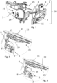
- Figure 1 shows a perspective view of a motor vehicle locking system 30 according to a first embodiment for a motor vehicle door or flap 32 not shown here.
- the motor vehicle door or flap 32 is in the Figures 2 and 3 only shown in a hint.
- the motor vehicle locking system 30 comprises a force transmission means 14 which is accessible to a user from outside the motor vehicle door or flap 32, wherein the force transmission means 14 is arranged on a support 26 for fastening, which is mounted inside the motor vehicle door or flap 32, and a motor vehicle lock 1 is provided for unlocking and/or opening the motor vehicle door or flap 32.
- the motor vehicle lock 1 has a locking mechanism 2 with a drive motor for actuating the locking mechanism 2.
- the locking mechanism 2 comprises a rotatable rotary latch, a pawl for releasing the rotary latch, a locking and/or unlocking mechanism and a drive motor for actuating the locking mechanism.
- the drive motor is controlled by a main control unit of the motor vehicle.
- the drive motor is only actuated by the main control unit if an authorized user has previously authenticated himself with an electronic identification transmitter.
- a locking bolt is arranged on one side of the body of the motor vehicle, which interacts with the rotary latch of the motor vehicle lock 1.
- a handle 31 can be provided for opening the motor vehicle door or flap 32.
- the motor vehicle door or flap 32 is locked using a motor vehicle locking system 30 and can be opened using a handle 31 designed as a handle. More precisely, the motor vehicle door or flap 32 is locked using one of the motor vehicle lock 1, so that actuation of the handle 31 remains ineffective when the motor vehicle lock 1 is locked.
- the handle 31 designed as a grip, is pivotally mounted on the carrier 26 and can be operated from the outside by a user to open the motor vehicle door or flap 32. This process is known from the prior art, which is why further details will not be discussed, particularly since the invention is also directed more towards emergency operation.
- a force transmission means 14 with a locking module 9 arranged on the motor vehicle lock 1 is provided for the access authorization check and for unlocking and/or opening.
- the motor vehicle lock 1 has a rotatably mounted actuating means 7.
- the actuating means 7 is also connected to the locking and/or unlocking mechanism. In order to unlock and/or open the motor vehicle lock 1 from the outside, the actuating means 7 can be actuated using the force transmission means 14.
- the force transmission means 14 comprises an output element 15 and an emergency actuation element 16 with an actuation section 27 formed on an outer side of the emergency actuation element 16 for actuation by the user, in particular in the form of a slot 18 and/or knurling 28, and a shaft 20 for connecting the emergency actuation element 16 and the output element 15.
- the shaft 20 and the output element 15 are connected to one another in an articulated and positively locking manner.
- a handle 31 can be provided for opening the motor vehicle door or flap 32.
- the motor vehicle door or flap 32 is locked using a motor vehicle locking system 30 and can be opened using a handle 31 designed as a handle.
- the motor vehicle door or flap 32 is locked by means of a locking and/or unlocking mechanism, so that actuation of the handle 31 has no effect when the motor vehicle lock 1 is in the locked state.
- the handle 31, designed as a handle is pivotally mounted on the carrier 26 and can be actuated from the outside by a user to open the motor vehicle door or flap 32, the carrier 26 being fastened to the inside of the motor vehicle door or flap 32.
- At least one opening for the power transmission means 14 or the handle 31 to pass through is formed in the motor vehicle door or flap 32 in order to fasten the power transmission means 14 or the handle 31 to the carrier 26.
- control unit 22 which is arranged within the locking module 9, wherein the locking module 9 is attached to the housing of the motor vehicle lock 1. Furthermore, the control unit 22 has an authentication device for authenticating the authorized user.
- the authentication device is only active in an emergency and checks whether an authorized user wants to gain access to the motor vehicle. To do this, in an emergency a user sends an access signal using, for example, a smartphone or an NFC card to the authentication device, which forwards the access signal to the control unit 22.
- the control unit 22 checks the access signal and evaluates whether the user is authorized.
- the authentication device can be an active or passive component which either has its own energy source, such as a button cell, for its operation or receives energy from outside during and for the authentication process. If the control unit 22 detects an authorized user, the control unit 22 activates a locking drive 12 arranged in the locking module 9.
- the authentication device has an NFC communication device or a BLE communication device, wherein the NFC communication device is provided with an antenna (not shown in more detail) for the external energy supply of the locking drive 12 and for authenticating an authorized user.
- the NFC communication device can be accommodated in a cavity of the handle 31.
- the NFC communication device has a power receiver, wherein the power receiver is the emergency energy storage device and is designed to supply the emergency actuator with energy in emergency operation and after authentication of an authorized user.
- the power receiver can also alternatively be connected to the emergency energy storage device and be designed to transmit to the emergency energy storage device the energy that was transferred to the power receiver with the aid of an NFC interface via a smartphone.
- the NFC communication device is connected to the locking module with an electrical line and/or signal line.
- the power transmission means 14 can have a USB interface 23 for supplying energy to the locking module 9.
- the BLE communication device is used, it is arranged within the blocking module 9, whereby the power supply is provided by means of an energy storage device arranged within the blocking module 9.
- the Energy storage can be designed as a capacitor and/or as an accumulator.
- the BLE communication device is connected to the power transmission means 14 by means of an electrical line 29 for power transmission.
- the power transmission means 14 has a USB interface 23 for supplying energy to the locking module 9.
- FIG. 2 shows a perspective view of a motor vehicle locking system according to a second embodiment.
- the motor vehicle locking system 30 comprises a force transmission means 14 which is accessible to a user from outside the motor vehicle door or flap 32, wherein the force transmission means 14 is arranged on a carrier 26 which serves for fastening and which is mounted inside the motor vehicle door or flap 32, and a motor vehicle lock 1 is provided for unlocking and/or opening the motor vehicle door or flap 32.
- the motor vehicle lock 1 has a locking mechanism 2 with a drive motor for actuating the locking mechanism 2.
- the locking mechanism 2 comprises a rotatable rotary latch, a pawl for releasing the rotary latch, a locking and/or unlocking mechanism and a drive motor for actuating the locking mechanism.
- the drive motor is controlled by a main control unit of the motor vehicle.
- the drive motor is only activated by the main control unit if an authorized user has previously authenticated himself with an electronic identification transmitter.
- a locking bolt is arranged on one side of the body of the motor vehicle, which interacts with the rotary latch of the motor vehicle lock 1. This process is known from the prior art, which is why further details are not discussed, especially since the invention is also directed more towards emergency operation.
- a force transmission means 14 with a locking module 9 arranged on the motor vehicle lock 1 is provided for the access authorization check and for unlocking and/or opening.
- the motor vehicle lock 1 has a rotatably mounted actuating means 7.
- the actuating means 7 is also connected to the locking and/or unlocking mechanism.
- the actuating means 7 can be actuated using the force transmission means 14.
- the force transmission means 14 comprises an output element 15 and an emergency actuating element 16 with an actuating section 27 formed on an outside of the emergency actuating element 16.
- a handle 31 can be provided for opening the motor vehicle door or flap 32.
- the motor vehicle door or flap 32 is locked using a motor vehicle locking system 30 and can be opened using a handle 31 designed as a handle. More precisely, the motor vehicle door or flap 32 is locked using a locking and/or unlocking mechanism, so that actuation of the handle 31 has no effect when the motor vehicle lock 1 is in the locked state.
- the handle 31, designed as a grip, is pivotally mounted on the carrier 26 and can be operated from the outside by a user to open the motor vehicle door or flap 32, wherein the carrier 26 is attached to the inside of the motor vehicle door or flap 32.
- At least one opening for the power transmission means 14 or the handle 31 to pass through is formed in the motor vehicle door or flap 32 in order to attach the power transmission means 14 or the handle 31 to the carrier 26.
- control unit 22 which is arranged within the locking module 9, wherein the locking module 9 is attached to the housing of the motor vehicle lock 1. Furthermore, the control unit 22 has an authentication device for authenticating the authorized user.
- the authentication device is only active in an emergency and checks whether an authorized user wants to gain access to the motor vehicle. To do this, in an emergency a user sends an access signal using, for example, a smartphone or an NFC card to the authentication device, which forwards the access signal to the control unit 22.
- the control unit 22 checks the access signal and evaluates whether the user is authorized.
- the authentication device can be an active or passive component which either has its own energy source, such as a button cell, for its operation or receives energy from outside during and for the authentication process. If the control unit 22 detects an authorized user, the control unit 22 activates a locking drive 12 arranged in the locking module 9.
- the authentication device has an NFC communication device for signal transmission and power transmission with an antenna (not shown in detail).
- the NFC communication device can be accommodated in a cavity of the handle 31.
- the NFC communication device also has a power receiver, wherein the power receiver is the emergency energy storage device and is designed to supply the emergency actuator with energy in emergency operation and after authentication of an authorized user.
- the power receiver can also alternatively be connected to the emergency energy storage device and be designed to transmit to the emergency energy storage device the energy that was transferred to the power receiver with the aid of an NFC interface via a smartphone.
- the NFC communication device is also connected to the locking module with an electrical line and/or signal line.
- the power transmission means 14 can have a USB interface 23 for supplying energy to the locking module 9.
- Figure 3 shows a perspective view of a motor vehicle locking system according to a third embodiment.
- the motor vehicle locking system 30 comprises a force transmission means 14 which is accessible to a user from outside the motor vehicle door or flap 32, wherein the force transmission means 14 is arranged on a support 26 which serves for fastening and which is mounted inside the motor vehicle door or flap 32, and a motor vehicle lock 1 is provided for unlocking and/or opening the motor vehicle door or flap 32.
- the motor vehicle lock 1 has a locking mechanism 2 with a drive motor for actuating the locking mechanism 2.
- the locking mechanism 2 comprises a rotatable rotary latch, a pawl for releasing the rotary latch, a locking and/or unlocking mechanism and a drive motor for actuating the locking mechanism.
- the drive motor is controlled by a main control unit of the motor vehicle.
- the drive motor is only actuated by the main control unit if an authorized user has previously authenticated himself with an electronic identification transmitter. Furthermore, a locking bolt is arranged on one side of the body of the motor vehicle, which interacts with the rotary latch of the motor vehicle lock 1. This process is known from the prior art, which is why further details will not be discussed, especially since the invention is also directed more towards emergency operation.
- a force transmission means 14 with a locking module 9 arranged on the motor vehicle lock 1 is provided for the access authorization check and for unlocking and/or opening.
- the motor vehicle lock 1 has a rotatably mounted actuating means 7.
- the actuating means 7 is also connected to the locking and/or unlocking mechanism. In order to unlock and/or open the motor vehicle lock 1 from the outside, the actuating means 7 can be actuated using the force transmission means 14.
- the force transmission means 14 comprises an output element 15 and an emergency actuation element 16 with an actuation section 27 formed on an outer side of the emergency actuation element 16 for actuation by the user, in particular in the form of a slot 18 and/or knurling 28, and a shaft 20 for connecting the emergency actuation element 16 and the output element 15.
- the shaft 20 and the output element 15 are connected to one another in an articulated and positively locking manner.
- a handle 31 can be provided for opening the motor vehicle door or flap 32.
- the motor vehicle door or flap 32 is locked using a motor vehicle locking system 30 and can be opened using a handle 31 designed as a handle.
- the motor vehicle door or flap 32 is locked by means of a locking and/or unlocking mechanism, so that actuation of the handle 31 has no effect when the motor vehicle lock 1 is in the locked state.
- the handle 31, designed as a handle is pivotally mounted on the carrier 26 and can be actuated from the outside by a user to open the motor vehicle door or flap 32, the carrier 26 being fastened to the inside of the motor vehicle door or flap 32.
- At least one opening for the power transmission means 14 or the handle 31 to pass through is formed in the motor vehicle door or flap 32 in order to fasten the power transmission means 14 or the handle 31 to the carrier 26.
- control unit 22 which is arranged within the locking module 9, wherein the locking module 9 is attached to the housing of the motor vehicle lock 1. Furthermore, the control unit 22 has an authentication device for authenticating the authorized user.
- the authentication device is only active in an emergency and checks whether an authorized user wants to gain access to the motor vehicle. To do this, in an emergency a user sends an access signal using, for example, a smartphone to the authentication device, which forwards the access signal to the control unit 22.
- the control unit 22 checks the access signal and evaluates whether the user is authorized.
- the authentication device can be an active or passive component which either has its own energy source, such as a button cell, for its operation or receives energy from outside during and for the authentication process. If the control unit 22 detects an authorized user, the control unit 22 activates a locking drive 12 arranged in the locking module 9.
- the authentication device has a BLE communication device.
- the BLE communication device is arranged within the locking module 9, wherein the BLE communication device is connected to the power transmission means 14 by means of an electrical line 29 for power transmission.
- the power transmission means 14 has a USB interface 23 for supplying power to the locking module 9.
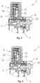
- Figure 4 shows a sectional view of the motor vehicle lock with the locking module in a release position.
- the locking element 11 can assume a blocking position or a release position for blocking and/or releasing the rotatably mounted actuating means 7, in particular a lock nut.
- the output element 15 of the force transmission element is inserted into the actuating means, in particular the lock nut, of the motor vehicle lock in such a way that a positive connection is formed between the two components.
- the locking element 11 is retracted.
- an operative connection is established between the force transmission means 14 and the locking and/or unlocking mechanism.
- Figure 5 shows a sectional view of a motor vehicle lock with a locking module in a blocking position.
- the locking element 11 In the blocking position, the locking element 11 is extended in such a way that the rotatably mounted actuating means 7, in particular a lock nut, can be blocked in its movement.
- the force transmission means 14 and the locking and/or unlocking mechanism is blocked.
- FIG 6 shows a perspective exploded view of the locking module.
- the locking module 9 comprises a housing 10 made of plastic, in which a locking element 11 for blocking and/or releasing the actuating means 7 and a locking drive 12 for driving the locking element 11 are arranged, wherein the locking module 9 is assigned a control unit 22 with an authentication device for authenticating an authorized user, wherein after the authentication process the locking element 11 can be controlled so that the motor vehicle lock 1 can be unlocked by means of the power transmission means 14.
- the control unit 22 and the locking drive 12 with the locking element 11 are attached to a circuit board, which in turn is connected to the housing 10 by means of a screw connection or a hot stamping connection.
- the two types of connection are in Figures 7 and 8 shown.
- the housing 10 can be provided with a cover 35 which is integrally connected to the housing 10.
- the cover 35 can be laser-welded to the housing 10.
- a through opening 13 for interaction with the actuating means 7, in particular a lock nut, is provided in the housing 10 of the locking module 9.
- the opening 13 is provided with a seal 33.
- the housing 10 can have a plug 34 for connecting an electrical line and/or signal line 29.
- At least one energy store for supplying the locking drive 12 can be arranged within the housing 10 of the locking module 9, wherein the energy store is designed as a capacitor and/or as an accumulator.
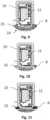
- Figure 9 shows a sectional view along the locking module with screw fastening 25 on the lock housing. Furthermore, the locking module 9 can have a fastening means 25 on the locking module side for fastening to the motor vehicle lock 1, in particular a flange. A housing-side fastening means 24 in the form of threaded holes is formed on the lock housing 8.
- Figure 10 shows a sectional view along the locking module with a welded connection to the lock housing.
- the locking module 9 can have a fastening means 25 on the locking module side for fastening to the motor vehicle lock 1, in particular a flange.
- the lock housing 8 is made of plastic.
- the housing 10 and the lock housing 8 are laser welded.
- Figure 11 shows a sectional view along the locking module with adhesive connection to the lock housing.
- the locking module 9 can have a fastening means 25 on the locking module side for fastening to the motor vehicle lock 1, in particular a flange.
- the lock housing 8 is made of plastic. The housing 10 and the lock housing 8 are glued.
- FIG 12 shows a perspective view of a power transmission means.
- the power transmission means 14 comprises: an output element 15 for connection to the actuating means 7, and an emergency actuating element 16 with an actuating section 27 formed on an outer side of the emergency actuating element 16 for actuation by the user, in particular in the form of a slot 18 and/or a knurling 28, and a shaft 20 for connecting the emergency actuating element 16 and the output element 15.
- the shaft 20 is rotatably mounted in a power transmission housing 37.
- One end of the shaft 20 facing the motor vehicle lock is connected to the output element 15 in a rotationally fixed and articulated manner, and an opposite end has the emergency actuation element 16.
- the emergency actuation element 16 is in turn rotatably mounted in the shaft, with the shaft 20 and the emergency actuation element 16 being connected to one another by means of a freewheel.
- the freewheel is in Figure 13 shown.
- the power transmission means 14 can have a USB interface 23.
- a status display in the form of LEDs can be provided to detect whether the locking module is ready for operation.
- Figure 13 shows a sectional view of the force transmission means 14 with a cover cap.
- the cover cap 39 can be fastened by means of a magnet 40, wherein the magnet 40 can be arranged on the force transmission means housing 37 and/or the cover cap 39.
- the force transmission means 14 has a fastening section 38 for fastening to the carrier 26.
- the fastening section can be designed in the form of a threaded hole for screwing to the carrier 26.
Landscapes
- Lock And Its Accessories (AREA)
Description
- Die Erfindung geht aus von einem Kraftfahrzeug-Schließsystem für eine Kraftfahrzeugtür oder Klappe mit den im Oberbegriff des Anspruchs 1 angegebenen Merkmalen.
- Kraftfahrzeug-Schließsystem für eine Kraftfahrzeugtür oder Klappe der eingangs bezeichneten Art ist beispielsweise bekannt, welches ein Kraftfahrzeugschloss mit einem Schlossgehäuse aufweist, in welchem ein Gesperre und Entriegelungsmechanismus bzw. Verriegelungsmechanismus zur Freigabe bzw. Blockieren des Gesperres z. B durch einen Elektromotor angeordnet ist, wobei das Freigeben bzw., Blockieren des Gesperres nur dann erfolgt, wenn sich ein berechtigter Benutzer vorher beim Hauptsteuergerät authentifiziert hat. Die Authentifizierung erfolgt durch ein Code-Austausch zwischen dem Hauptsteuergerät und einem elektronischen Schlüssel, welcher mit dem Benutzer getragen wird. Das Gesperre umfasst eine drehbar gelagerte Drehfalle zum Schließen bzw. Öffnen einer Kraftfahrzeugtür oder Klappe und eine zur Betätigung der Drehfalle vorgesehene Sperrklinke, welche mit dem Entriegelungsmechanismus bzw. Verriegelungsmechanismus zusammenwirkt.
- Bei einer solchen bekannten Kraftfahrzeug-Schließeinrichtung können verschiedene Notfälle eintreten, die ein wie vorstehend beschriebenes Zugangs-Szenario nicht möglich machen. Beispielsweise kann das Hauptsteuergerät aufgrund einer leeren Kraftfahrzeugbatterie nicht mehr mit dem elektronischen Schlüssel kommunizieren, um eine Legitimationsprüfung für den Zugang durchzuführen. Umgekehrt ist es auch denkbar, dass die Batterie des elektronischen Schlüssels leer ist, so dass dieser nicht mehr mit dem Kraftfahrzeug-Hauptsteuergerät zur Legitimationsprüfung kommunizieren kann.
- Im Stand der Technik ist es daher bekannt, dass das Kraftfahrzeug-Schließsystem einen sogenannten mechanischen Not-Schließzylinder aufweist. Ein solcher mechanischer Not-Schließzylinder wirkt mit einem mechanischen Not-Schlüssel zusammen, um das Kraftfahrzeug-Schließsystem manuell zu entriegeln bzw. in den Entriegelungszustand zu überführen, indem der mechanische Not-Schlüssel auf bekannte Weise in den mechanischen Not-Schließzylinder eingeführt und zur Entriegelung gedreht wird. Beim entriegelten Gesperre kann dann die Kraftfahrzeugtür oder Klappe mittels eines Türaussengriffes, welcher mit dem Kraftfahrzeugschloss zusammenwirkt, geöffnet werden.
- Solche Schlösser weisen eine nicht ausreichende Diebstahlsicherung aufgrund des mechanischen Not-Schlüssels und des mechanischen Not-Schließzylinders auf, wobei auch die Handhabung in einem Notfall nicht sehr komfortabel ist.
- Ein weiterer Nachteil ist bei derartigen Kraftfahrzeugschlössern, dass der mechanische Schlüssel die Gefahr eines Verlustes in sich birgt, denn die Beschaffung eines mechanischen Ersatzschlüssels ist kosten- und zeitintensiv und damit sehr aufwendig.
- Auch sind im Stand der Technik Notentriegelungsvorrichtungen bekannt, bei welchen versucht wird die Energie von außerhalb des Kraftfahrzeuges zuzuführen, um die Hauptsteuereinheit mit Strom zu versorgen. Dadurch ist es möglich, dass ein Benutzer sich beim Hauptsteuergerät mit einem mobilen Identifikationsgeber authentifizieren kann, um die Kraftfahrzeugschlösser durch das Hauptsteuergerät anzusteuern und zu entriegeln. Diese Vorgehensweise bewirkt, dass das ganze Fahrzeug geweckt wird, was zu einem sehr hohen Energieaufwand führt.
- Solche Kraftfahrzeug-Schließsysteme sind z.B. aus
DE102016103918A1 ,DE102016109566A1 ,DE202008003845U1 ,DE202016100521 U1 oderDE102006003023A1 bekannt. - Der Erfindung liegt die Aufgabe zugrunde eine Lösung zu schaffen, die auf konstruktiv einfache Weise ein verbessertes und für den Benutzer komfortableres Kraftfahrzeug-Schließsystem bereitstellt, durch welches die vorstehend genannten Nachteile vermieden werden und bei welchem auf kostengünstige Weise von der Verwendung eines mechanischen Not-Schließzylinders und eines mechanischen Not-Schlüssels abgesehen werden kann, wobei das Kraftfahrzeugschließsystem darüber hinaus hinsichtlich seiner Bedienung eine große Flexibilität aufweisen soll.
- Die erfindungsgemäße Aufgabe wird durch den kennzeichnenden Teil des Patentanspruchs 1 gelöst. Diese hat den Vorteil, dass beim Ausfall der Energieversorgung im Kraftfahrzeug ein autarker Sperrmodul mit eigener Steuereinheit am Kraftfahrzeugschloss und ein durch einen Benutzter von außerhalb des Kraftfahrzeugs betätigbares Kraftübertragungsmittel zur Entriegelung des Kraftfahrzeugschlosses vorgesehen ist, was dazu führt, dass weniger Energieaufwand benötigt wird. Die Energie wird lediglich für den Authentifizierungsvorgang und für die Betätigung eines Sperrelements des Sperrmoduls verbraucht, wobei nur ein einziges Kraftfahrzeugschloss angesteuert wird, sodass das ganze Kraftfahrzeug selbst nicht aufgeweckt werden muss.
- Sehr komfortabel und benutzerfreundlich ist die Konstruktion, wenn eine an dem Träger angeordnete Handhabe vorgesehen ist, durch welche die Kraftfahrzeugtür oder Klappe in dem entriegelten Zustand des Kraftfahrzeugschlosses öffenbar ist. Vorteilhafterweise kann das Gehäuse des Sperrmoduls mit einer durchgehenden Öffnung zum Zusammenwirken mit dem Betätigungsmittel versehen ist, wobei das Sperrelement eine Blockierstellung oder eine Freigabestellung zum Blockieren und/oder Freigeben des Betätigungsmittels aufweisen. Damit wird sichergestellt, dass das Betätigungsmittel durch das Sperrmodul blockiert oder freigegeben wird, wobei das bestehende Kraftfahrzeugschloss unwesentlich konstruktiv angepasst werden muss. Damit kann das Sperrmodul in einfacher Weise nachgerüstet werden.
- Sehr kostengünstig und einfach ist die Konstruktion, wenn das Schlossgehäuse ein gehäuseseitiges Befestigungsmittel, insbesondere mindestens eine Befestigungsöffnung mit einem Gewinde, und das Sperrmodul ein sperrmodulseitiges Befestigungsmittel, insbesondere einen Flansch, aufweist.
- Eine die Erfindung verbessernde Maßnahme sieht vor, dass das Sperrmodul mittels Laserschweißen oder mittels Klebeverbindung oder mittels Clipsverbindung am Schlossgehäuse befestigbar ist. Damit wird eine einfache Montage des Sperrmoduls erreicht.
- Eine die Erfindung verbessernde Maßnahme sieht vor, dass die Steuereinheit mit der Authentifizierungseinrichtung zum Authentifizieren des berechtigten Benutzers innerhalb des Gehäuses des Sperrmoduls angeordnet ist. Damit wird sichergestellt, dass der auf der Steuereinheit gespeicherte Schließcode zur Authentifizierung des berechtigten Benutzers vor Zugriff Dritter von außen innerhalb der Kraftfahrzeugtür manipulationssicher gelagert ist.
- Weiterhin kann gemäß der Erfindung vorgesehen sein, dass die Steuereinheit innerhalb des Gehäuses des Sperrmoduls und die Authentifizierungseinrichtung innerhalb der Handhabe zum Authentifizieren des berechtigten Benutzers angeordnet sind, wobei die Steuereinheit und die Authentifizierungseinrichtung über eine elektrische Leitung und/oder Signalleitung miteinander verbindbar sind. Durch die Verlagerung der Authentifizierungseinrichtung nach außen wird die Kommunikation mit einem mobilen Identifikationsgeber, insbesondere einem Smartphone verbessert, da es sich keine Metalteile wie z. B. ein Karosserieblech des Kraftfahrzeuges zwischen der Authentifizierungseinrichtung und dem mobilen Identifikationsgeber, insbesondere einem Smartphone, befinden.
- Vorteilhafterweise kann im Gehäuse ein Stecker zum Anschließen der elektrischen Leitung und/oder Signalleitung vorgesehen sein. Dadurch wird der Vorteil erziel, dass das Kraftfahrzeugschloss mit dem Sperrmodul flexibel aufgrund von unterschiedlichen Bauräumen bzw. unterschiedlichen KFZ-Varianten in der Kraftfahrzeugtür verbaut werden kann, indem eine passende elektrische Leitung und/oder Signalleitung abhängig von der KFZ-Ausführung auswählbar ist.
- Weiterhin kann gemäß der Erfindung vorgesehen sein, dass die Authentifizierungseinrichtung eine NFC-Kommunikationseinrichtung oder eine BLE-Kommunikationseinrichtung aufweist, wobei die NFC-Kommunikationseinrichtung zur externen Energieversorgung des Sperrantriebs und zum Authentifizieren eines berechtigten Benutzers vorgesehen ist. Durch den Einsatz der beiden Schnittstellen ist es möglich, dass ein Smartphone zum Authentifizieren des berechtigten Benutzers verwendet werden kann, da diese Schnittstellen mittlerweile standardmäßig im Smartphone verbaut sind. Einen besonderen Vorteil weist die NFC-Kommunikationseinrichtung auf, da diese in einem Bereich vom wenigen Zentimetern funktioniert, sodass die Sicherheit des Authentifizierungsvorgangs erheblich verbessert werden kann.
- Ebenfalls ist es denkbar, dass innerhalb des Gehäuses des Sperrmoduls mindestens ein Energiespeicher zur Versorgung des Sperrantriebs angeordnet ist, wobei der Energiespeicher als ein Kondensator oder ein Akkumulator ausgebildet ist. Damit wird eine externe Energieversorgung entbehrlich, da während eines Normalbetriebs der Energiespeicher von der Fahrzeugbatterie aufgeladen werden kann, um Notfall den Sperrmodul mit der Energie zu versorgen.
- Vorteilhafterweise kann das Kraftübertragungsmittel ein Abtriebselement zur Verbindung des Betätigungsmittels, und ein Notbetätigungselement mit einem auf einer Außenseite des Notbetätigungselements ausgebildeten Betätigungsabschnitt zum Betätigen durch den Benutzer, insbesondere in Form eines Schlitzes und/oder einer Rändelung, und eine Welle zur Verbindung des Notbetätigungselements und des Abtriebselementes umfassen. Durch die Rändelung wird eine komfortable Bedienung bereitgestellt, welche ohne zusätzliches Werkzeug auskommt. Durch die Ausbildung des Schlitzes kann z. B. eine Münze zur Betätigung des Notbetätigungselements verwendet werden. Es wird davon ausgegangen, dass eine Münze meistens beim Benutzer vorhanden ist.
- In einer weiteren die Erfindung verbessernden Ausführungsform kann das Kraftübertragungsmittel eine USB-Schnittstelle zur Energieversorgung des Sperrmoduls aufweisen. Dadurch ist möglich von einer externen Vorrichtung wie eine Powerbank, Smartphone oder mobiler Identifikationsgeber die Energie von außerhalb eines Kraftfahrzeugs in das Kraftfahrzeug-Schließsystem zuzuführen. Es wird davon ausgegangen, dass es derzeit viele Geräte gibt, welche über eine standartmäßige USB-Schnittstelle verfügen. Durch die Verwendung der USB-Schnittstelle, insbesondere eine USB-Schnittstelle Typ C oder Typ B, wird schneller Energietransport ermöglicht und somit der Bedienungskomfort erheblich erhöht. Sehr kostengünstig und einfach ist die Konstruktion, wenn die Authentifizierung des berechtigten Benutzers mittels eines Smartphones, erfolgt. Dadurch wird der Vorrichtungsaufwand minimiert, da der mechanische Schlüssel und der mobile Identifikationsgeber entfallen können. Ferner wird der Komfort verbessert, da nur ein Identifikationsgerät, insbesondere ein Smartphone, vom Benutzer getragen wird. Es wird davon ausgegangen, dass derzeit fast jeder Benutzer ein Smartphone bei sich trägt.
- Eine die Erfindung verbessernde Maßnahme sieht vor, dass das Abtriebselement mit dem Notbetätigungselement über einen Freilauf bis zu einem vorbestimmten Drehmoment drehfest verbindbar ist. Durch den Freilauf wird sichergestellt, dass kein gewaltsames Verdrehen des Notbetätigungselements stattfindet, wenn das Betätigungsmittel des Kraftfahrzeugschlosses durch den Sperrmodul blockiert ist.
- Der Rahmen der Erfindung ist nur durch die Ansprüche definiert.
- Weitere Einzelheiten, Merkmale und Vorteile des Gegenstandes der Erfindung ergeben sich aus der nachfolgenden Beschreibung im Zusammenhang mit der Zeichnung, in der beispielhafte bevorzugte Ausführungsbeispiele der Erfindung dargestellt sind. In der Zeichnung zeigt:
-
Figur 1 eine perspektivische Darstellung eines Kraftfahrzeug-Schließsystems gemäß einer ersten Ausführungsform, -
Figur 2 eine perspektivische Darstellung eines Kraftfahrzeug-Schließsystems gemäß einer zweiten Ausführungsform, -
Figur 3 eine perspektivische Darstellung eines Kraftfahrzeug-Schließsystems gemäß einer dritten Ausführungsform, -
Figur 4 eine Schnittdarstellung eines Kraftfahrzeugschlosses mit einem Sperrmodul in einer Freigabestellung, -
Figur 5 eine Schnittdarstellung eines Kraftfahrzeugschlosses mit einem Sperrmodul in einer Blockierstellung, -
Figur 6 eine perspektivische Explosionsdarstellung des Sperrmoduls, -
Figur 7 eine Schnittdarstellung des Sperrmoduls mit verschraubter Steuereinheit, -
Figur 8 eine Schnittdarstellung des Sperrmoduls mit heißgeprägter Steuereinheit, -
Figur 9 eine Schnittdarstellung entlang des Sperrmoduls mit Schraubbefestigung am Schlossgehäuse, -
Figur 10 eine Schnittdarstellung entlang des Sperrmoduls mit Schweißverbindung am Schlossgehäuse, -
Figur 11 eine Schnittdarstellung entlang des Sperrmoduls mit Klebeverbindung am Schlossgehäuse, -
Figur 12 eine perspektivische Darstellung eines Kraftübertragungsmittels, -
Figur 13 eine Schnittdarstellung des Kraftübertragungsmittels mit einer Abdeckkappe, - In den nachfolgenden Figuren werden für die gleichen technischen Merkmale auch von unterschiedlichen Ausführungsbeispielen die identischen Bezugszeichen verwendet.
- Die drei folgenden Ausführungsformen werden anhand der Energieversorgung eines Sperrmoduls 9 und einer Kommunikationsart des Sperrmoduls 9 mit einem mobilen Identifikationsgeber unterschieden.
-
Figur 1 zeigt eine perspektivische Darstellung eines Kraftfahrzeug-Schließsystems 30 gemäß einer ersten Ausführungsform für eine hier nicht gezeigte Kraftfahrzeugtür oder Klappe 32. Die Kraftfahrzeugtür oder Klappe 32 ist in denFiguren 2 und 3 nur angedeutet gezeigt. - Das Kraftfahrzeug-Schließsystem 30 umfasst ein Kraftübertragungsmittel 14, welches von außerhalb der Kraftfahrzeugtür oder Klappe 32 für einen Benutzer zugänglich ist, wobei das Kraftübertragungsmittel 14 an einem zur Befestigung dienenden Träger 26 angeordnet ist, welcher innerhalb der Kraftfahrzeugtür oder Klappe 32 gelagert ist sowie ein Kraftfahrzeugschloss 1 zum Entriegeln und/oder Öffnen der Kraftfahrzeugtür oder Klappe 32 vorgesehen ist. Dazu weist das Kraftfahrzeugschloss 1 ein Gesperre 2 mit einem Antriebsmotor zu Betätigung des Gesperres 2 auf. Das Gesperre 2 umfasst eine verdrehbare Drehfalle, eine Sperrklinke zum Freigeben der Drehfalle, einen Verriegelungs -und/oder Entriegelungsmechanismus und einen Antriebsmotor zur Betätigung des Verriegelungsmechanismus auf. Der Antriebsmotor wird von einer Hauptsteuereinheit des Kraftfahrzeuges gesteuert. Der Antriebsmotor wird nur dann durch die Hauptsteuereinheit betätigt, wenn sich ein berechtigter Benutzer mit einem elektronischen Identifikationsgeber vorher authentifiziert hat. Ferner ist ein Schließriegel an einer Karosserieseite des Kraftfahrzeuges angeordnet, welcher mit der Drehfalle des Kraftfahrzeugschlosses 1 zusammenwirkt. Optional kann eine Handhabe 31 zum Öffnen der Kraftfahrzeugtür oder Klappe 32 vorgesehen sein. Die Kraftfahrzeugtür oder Klappe 32 ist mit Hilfe eines Kraftfahrzeug-Schließsystems 30 verschlossen und kann mittels einer als Griff ausgebildeten Handhabe 31 geöffnet werden. Genauer gesagt ist die Kraftfahrzeugtür oder Klappe 32 mittels eines des Kraftfahrzeugschlosses 1 verschlossen, so dass eine Betätigung der Handhabe 31 in einem Verriegelungszustand des Kraftfahrzeugschlosses 1 wirkungslos bleibt. Die als Griff ausgebildete Handhabe 31 ist an dem Träger 26 schwenkbar gelagert und von außen für einen Benutzer zum Öffnen der Kraftfahrzeugtür oder Klappe 32 betätigbar. Dieser Ablauf ist aus dem Stand der Technik bekannt, weshalb auf weitere Details nicht näher eingegangen wird, insbesondere da sich die Erfindung auch vielmehr auf einen Notbetrieb richtet.
- Für den Notbetrieb ist erfindungsgemäß für die Zugangsberechtigungsprüfung und für die Entriegelung und/ oder für das Öffnen ein Kraftübertragungsmittel 14 mit einem am Kraftfahrzeugschloss 1 angeordneten Sperrmodul 9 vorgesehen. Das Kraftfahrzeugschloss 1 weist ein drehbar gelagertes Betätigungsmittel 7 auf. Das Betätigungsmittel 7 ist ebenfalls mit dem Verriegelungs -und/oder Entriegelungsmechanismus verbunden. Um das Kraftfahrzeugschloss 1 von außen zu entriegeln und/oder zu öffnen ist das Betätigungsmittel 7 ist mithilfe des Kraftübertragungsmittels 14 betätigbar. Dazu umfasst das Kraftübertragungsmittel 14 ein Abtriebselement 15 und ein Notbetätigungselement 16 mit einem auf einer Außenseite des Notbetätigungselements 16 ausgebildeten Betätigungsabschnitt 27 zum Betätigen durch den Benutzer, insbesondere in Form eines Schlitzes 18 und/oder einer Rändelung 28 , und eine Welle 20 zur Verbindung des Notbetätigungselements 16 und des Abtriebselementes 15. Die Welle 20 und das Abtriebselement 15 sind gelenkig und formschlüssig mit einander verbunden. Dadurch können unterschiedliche Einbausituationen des Kraftfahrzeugschlosses 1 abgedeckt werden. Optional kann eine Handhabe 31 zum Öffnen der Kraftfahrzeugtür oder Klappe 32 vorgesehen sein. Die Kraftfahrzeugtür oder Klappe 32 ist mit Hilfe eines Kraftfahrzeug-Schließsystems 30 verschlossen und kann mittels einer als Griff ausgebildeten Handhabe 31 geöffnet werden. Genauer gesagt ist die Kraftfahrzeugtür oder Klappe 32 mittels eines Verriegelungs -und/oder Entriegelungsmechanismus verriegelt, so dass eine Betätigung der Handhabe 31 in einem Verriegelungszustand des Kraftfahrzeugschlosses 1 wirkungslos bleibt. Die als Griff ausgebildete Handhabe 31 ist an dem Träger 26 schwenkbar gelagert und von außen für einen Benutzer zum Öffnen der Kraftfahrzeugtür oder Klappe 32 betätigbar, wobei der Träger 26 innenseitig an der Kraftfahrzeugtür oder Klappe 32 befestigt ist. In der Kraftfahrzeugtür oder Klappe 32 ist mindestens eine Öffnung zur Durchführung des Kraftübertragungsmittels 14 bzw. der Handhabe 31 ausgebildet, um das Kraftübertragungsmittels 14 bzw. die Handhabe 31 an dem Träger 26 zu befestigen.
- Im Notfall erfolgt die Authentifizierung mittels einer separaten Steuereinheit 22, welche innerhalb des Sperrmoduls 9 angeordnet ist, wobei das Sperrmodul 9 am Gehäuse des Kraftfahrzeugschlosses 1 befestigt ist. Ferner weist die Steuereinheit 22 eine Authentifizierungseinrichtung zum Authentifizieren des berechtigten Benutzers auf.
- Die Authentifizierungseinrichtung ist nur in Notfall aktiv und überprüft, ob ein berechtigter Benutzer Zugang zu dem Kraftfahrzeug erlangen möchte. Hierzu sendet ein Benutzer im Notfall ein Zugangssignal mittels beispielsweise eines Smartphones oder einer NFC-Karte an die Authentifizierungseinrichtung, welche das Zugangssignal an die Steuereinheit 22 weiterleitet. In der Steuereinheit 22 wird das Zugangssignal überprüft und auswertet, ob es sich um einen berechtigten Benutzer handelt. Dabei kann es sich bei der Authentifizierungseinrichtung um ein aktives oder passives Bauteil handeln, welches zu seinem Betrieb entweder selbst eine Energiequelle, wie zum Beispiel eine Knopfzelle, aufweist oder Energie von außerhalb beim und für den Authentifizierungsvorgang erhält. Stellt die Steuereinheit 22 einen berechtigten Benutzer fest, so setzt die Steuereinheit 22 einen im Sperrmodul 9 angeordneten Sperrantrieb 12 in Betrieb.
- Die Authentifizierungseinrichtung weist eine NFC-Kommunikationseinrichtung oder eine BLE-Kommunikationseinrichtung auf, wobei die NFC-Kommunikationseinrichtung mit einer nicht näher dargestellte Antenne zur externen Energieversorgung des Sperrantriebs 12 und zum Authentifizieren eines berechtigten Benutzers vorgesehen ist. Die NFC-Kommunikationseinrichtung kann in einem Hohlraum der Handhabe 31 aufgenommen werden. Ferner weist die NFC-Kommunikationseinrichtung mit einem Power-Receiver auf, wobei der Power-Receiver der Not-Energiespeicher ist und in dem Notbetrieb und nach Authentifizierung eines berechtigten Benutzers den Not-Stellantrieb mit Energie versorgend ausgebildet ist. Der Power-Receiver kann auch alternativ mit dem Not-Energiespeicher verbunden sein und auf den Not-Energiespeicher die Energie, welche mit Hilfe von einer NFC-Schnittstelle über einen Smartphone auf den Power-Receiver übertragen wurde, übertragend ausgebildet sein. Ferner ist die NFC-Kommunikationseinrichtung mit einer elektrischen Leitung und/oder Signalleitung mit dem Sperrmodul verbunden. Optional kann das Kraftübertragungsmittel 14 eine USB-Schnittstelle 23 zur Energieversorgung des Sperrmoduls 9 aufweisen.
- Wenn die BLE-Kommunikationseinrichtung verwendet wird, wird diese innerhalb des Sperrmoduls 9 angeordnet, wobei die Stromversorgung mittels eines innerhalb des Sperrmoduls 9 angeordneten Energiespeichers erfolgt. Dabei kann der Energiespeicher als ein Kondensator und/oder als ein Akkumulator ausgebildet sein. Die BLE-Kommunikationseinrichtung ist mittels einer elektrischen Leitung 29 zur Stromübertragung mit dem Kraftübertragungsmittel 14 verbunden. Das Kraftübertragungsmittel 14 weist eine USB-Schnittstelle 23 zur Energieversorgung des Sperrmoduls 9 auf.
-
Figur 2 zeigt eine perspektivische Darstellung eines Kraftfahrzeug-Schließsystems gemäß einer zweiten Ausführungsform. Das Kraftfahrzeug-Schließsystem 30 umfasst ein Kraftübertragungsmittel 14, welches von außerhalb der Kraftfahrzeugtür oder Klappe 32 für einen Benutzer zugänglich ist, wobei das Kraftübertragungsmittel 14 an einem zur Befestigung dienenden Träger 26 angeordnet ist, welcher innerhalb der Kraftfahrzeugtür oder Klappe 32 gelagert ist sowie ein Kraftfahrzeugschloss 1 zum Entriegeln und/oder Öffnen der Kraftfahrzeugtür oder Klappe 32 vorgesehen ist. Dazu weist das Kraftfahrzeugschloss 1 ein Gesperre 2 mit einem Antriebsmotor zu Betätigung des Gesperres 2 auf. Das Gesperre 2 umfasst auf eine verdrehbare Drehfalle, eine Sperrklinke zum Freigeben der Drehfalle, einen Verriegelungs - und/oder Entriegelungsmechanismus und einen Antriebsmotor zur Betätigung des Verriegelungsmechanismus auf. Der Antriebsmotor wird von einer Hauptsteuereinheit des Kraftfahrzeuges gesteuert. Der Antriebsmotor wird nur dann durch die Hauptsteuereinheit betätigt, wenn sich ein berechtigter Benutzer mit einem elektronischen Identifikationsgeber vorher authentifiziert hat. Ferner ist ein Schließriegel an einer Karosserieseite des Kraftfahrzeuges angeordnet, welcher mit der Drehfalle des Kraftfahrzeugschlosses 1 zusammenwirkt. Dieser Ablauf ist aus dem Stand der Technik bekannt, weshalb auf weitere Details nicht näher eingegangen wird, insbesondere da sich die Erfindung auch vielmehr auf einen Notbetrieb richtet. - Für den Notbetrieb ist erfindungsgemäß für die Zugangsberechtigungsprüfung und für die Entriegelung und/ oder für das Öffnen ein Kraftübertragungsmittel 14 mit einem am Kraftfahrzeugschloss 1 angeordneten Sperrmodul 9 vorgesehen. Das Kraftfahrzeugschloss 1 weist ein drehbar gelagertes Betätigungsmittel 7 auf. Das Betätigungsmittel 7 ist ebenfalls mit dem Verriegelungs -und/oder Entriegelungsmechanismus verbunden. Um das Kraftfahrzeugschloss 1 von außen zu entriegeln und/oder zu öffnen ist das Betätigungsmittel 7 ist mithilfe des Kraftübertragungsmittels 14 betätigbar. Dazu umfasst das Kraftübertragungsmittel 14 ein Abtriebselement 15 und ein Notbetätigungselement 16 mit einem auf einer Außenseite des Notbetätigungselements 16 ausgebildeten Betätigungsabschnitt 27 zum Betätigen durch den Benutzer, insbesondere in Form eines Schlitzes 18 und/oder einer Rändelung 28 , und eine Welle 20 zur Verbindung des Notbetätigungselements 16 und des Abtriebselementes 15. Die Welle 20 und das Abtriebselement 15 sind gelenkig und formschlüssig mit einander verbunden. Dadurch können unterschiedliche Einbausituationen des Kraftfahrzeugschlosses 1 abgedeckt werden. Optional kann eine Handhabe 31 zum Öffnen der Kraftfahrzeugtür oder Klappe 32 vorgesehen sein. Die Kraftfahrzeugtür oder Klappe 32 ist mit Hilfe eines Kraftfahrzeug-Schließsystems 30 verschlossen und kann mittels einer als Griff ausgebildeten Handhabe 31 geöffnet werden. Genauer gesagt ist die Kraftfahrzeugtür oder Klappe 32 mittels eines Verriegelungs -und/oder Entriegelungsmechanismus verriegelt, so dass eine Betätigung der Handhabe 31 in einem Verriegelungszustand des Kraftfahrzeugschlosses 1 wirkungslos bleibt. Die als Griff ausgebildete Handhabe 31 ist an dem Träger 26 schwenkbar gelagert und von außen für einen Benutzer zum Öffnen der Kraftfahrzeugtür oder Klappe 32 betätigbar, wobei der Träger 26 innenseitig an der Kraftfahrzeugtür oder Klappe 32 befestigt ist. In der Kraftfahrzeugtür oder Klappe 32 ist mindestens eine Öffnung zur Durchführung des Kraftübertragungsmittels 14 bzw. der Handhabe 31 ausgebildet, um das Kraftübertragungsmittels 14 bzw. die Handhabe 31 an dem Träger 26 zu befestigen.
- Im Notfall erfolgt die Authentifizierung mittels einer separaten Steuereinheit 22, welche innerhalb des Sperrmoduls 9 angeordnet ist, wobei das Sperrmodul 9 am Gehäuse des Kraftfahrzeugschlosses 1 befestigt ist. Ferner weist die Steuereinheit 22 eine Authentifizierungseinrichtung zum Authentifizieren des berechtigten Benutzers auf.
- Die Authentifizierungseinrichtung ist nur in Notfall aktiv und überprüft, ob ein berechtigter Benutzer Zugang zu dem Kraftfahrzeug erlangen möchte. Hierzu sendet ein Benutzer im Notfall ein Zugangssignal mittels beispielsweise eines Smartphones oder einer NFC-Karte an die Authentifizierungseinrichtung, welche das Zugangssignal an die Steuereinheit 22 weiterleitet. In der Steuereinheit 22 wird das Zugangssignal überprüft und auswertet, ob es sich um einen berechtigten Benutzer handelt. Dabei kann es sich bei der Authentifizierungseinrichtung um ein aktives oder passives Bauteil handeln, welches zu seinem Betrieb entweder selbst eine Energiequelle, wie zum Beispiel eine Knopfzelle, aufweist oder Energie von außerhalb beim und für den Authentifizierungsvorgang erhält. Stellt die Steuereinheit 22 einen berechtigten Benutzer fest, so setzt die Steuereinheit 22 einen im Sperrmodul 9 angeordneten Sperrantrieb 12 in Betrieb.
- Die Authentifizierungseinrichtung weist eine NFC-Kommunikationseinrichtung zur Signalübertragung und zur Stromübertragung mit einer nicht näher dargestellte Antenne auf. Die NFC-Kommunikationseinrichtung kann in einem Hohlraum der Handhabe 31 aufgenommen werden. Ferner weist die NFC-Kommunikationseinrichtung mit einem Power-Receiver auf, wobei der Power-Receiver der Not-Energiespeicher ist und in dem Notbetrieb und nach Authentifizierung eines berechtigten Benutzers den Not-Stellantrieb mit Energie versorgend ausgebildet ist. Der Power-Receiver kann auch alternativ mit dem Not-Energiespeicher verbunden sein und auf den Not-Energiespeicher die Energie, welche mit Hilfe von einer NFC-Schnittstelle über einen Smartphone auf den Power-Receiver übertragen wurde, übertragend ausgebildet sein. Ferner ist die NFC-Kommunikationseinrichtung mit einer elektrischen Leitung und/oder Signalleitung mit dem Sperrmodul verbunden. Optional kann das Kraftübertragungsmittel 14 eine USB-Schnittstelle 23 zur Energieversorgung des Sperrmoduls 9 aufweisen.
-
Figur 3 zeigt eine perspektivische Darstellung eines Kraftfahrzeug-Schließsystems gemäß einer dritten Ausführungsform. - Das Kraftfahrzeug-Schließsystem 30 umfasst ein Kraftübertragungsmittel 14, welches von außerhalb der Kraftfahrzeugtür oder Klappe 32 für einen Benutzer zugänglich ist, wobei das Kraftübertragungsmittel 14 an einem zur Befestigung dienenden Träger 26 angeordnet ist, welcher innerhalb der Kraftfahrzeugtür oder Klappe 32 gelagert ist sowie ein Kraftfahrzeugschloss 1 zum Entriegeln und/oder Öffnen der Kraftfahrzeugtür oder Klappe 32 vorgesehen ist. Dazu weist das Kraftfahrzeugschloss 1 ein Gesperre 2 mit einem Antriebsmotor zu Betätigung des Gesperres 2 auf. Das Gesperre 2 umfasst auf eine verdrehbare Drehfalle, eine Sperrklinke zum Freigeben der Drehfalle, einen Verriegelungs -und/oder Entriegelungsmechanismus und einen Antriebsmotor zur Betätigung des Verriegelungsmechanismus auf. Der Antriebsmotor wird von einer Hauptsteuereinheit des Kraftfahrzeuges gesteuert. Der Antriebsmotor wird nur dann durch die Hauptsteuereinheit betätigt, wenn sich ein berechtigter Benutzer mit einem elektronischen Identifikationsgeber vorher authentifiziert hat. Ferner ist ein Schließriegel an einer Karosserieseite des Kraftfahrzeuges angeordnet, welcher mit der Drehfalle des Kraftfahrzeugschlosses 1 zusammenwirkt. Dieser Ablauf ist aus dem Stand der Technik bekannt, weshalb auf weitere Details nicht näher eingegangen wird, insbesondere da sich die Erfindung auch vielmehr auf einen Notbetrieb richtet.
- Für den Notbetrieb ist erfindungsgemäß für die Zugangsberechtigungsprüfung und für die Entriegelung und/ oder für das Öffnen ein Kraftübertragungsmittel 14 mit einem am Kraftfahrzeugschloss 1 angeordneten Sperrmodul 9 vorgesehen. Das Kraftfahrzeugschloss 1 weist ein drehbar gelagertes Betätigungsmittel 7 auf. Das Betätigungsmittel 7 ist ebenfalls mit dem Verriegelungs -und/oder Entriegelungsmechanismus verbunden. Um das Kraftfahrzeugschloss 1 von außen zu entriegeln und/oder zu öffnen ist das Betätigungsmittel 7 mithilfe des Kraftübertragungsmittels 14 betätigbar. Dazu umfasst das Kraftübertragungsmittel 14 ein Abtriebselement 15 und ein Notbetätigungselement 16 mit einem auf einer Außenseite des Notbetätigungselements 16 ausgebildeten Betätigungsabschnitt 27 zum Betätigen durch den Benutzer, insbesondere in Form eines Schlitzes 18 und/oder einer Rändelung 28 , und eine Welle 20 zur Verbindung des Notbetätigungselements 16 und des Abtriebselementes 15. Die Welle 20 und das Abtriebselement 15 sind gelenkig und formschlüssig mit einander verbunden. Dadurch können unterschiedliche Einbausituationen des Kraftfahrzeugschlosses 1 abgedeckt werden. Optional kann eine Handhabe 31 zum Öffnen der Kraftfahrzeugtür oder Klappe 32 vorgesehen sein. Die Kraftfahrzeugtür oder Klappe 32 ist mit Hilfe eines Kraftfahrzeug-Schließsystems 30 verschlossen und kann mittels einer als Griff ausgebildeten Handhabe 31 geöffnet werden. Genauer gesagt ist die Kraftfahrzeugtür oder Klappe 32 mittels eines Verriegelungs -und/oder Entriegelungsmechanismus verriegelt, so dass eine Betätigung der Handhabe 31 in einem Verriegelungszustand des Kraftfahrzeugschlosses 1 wirkungslos bleibt. Die als Griff ausgebildete Handhabe 31 ist an dem Träger 26 schwenkbar gelagert und von außen für einen Benutzer zum Öffnen der Kraftfahrzeugtür oder Klappe 32 betätigbar, wobei der Träger 26 innenseitig an der Kraftfahrzeugtür oder Klappe 32 befestigt ist. In der Kraftfahrzeugtür oder Klappe 32 ist mindestens eine Öffnung zur Durchführung des Kraftübertragungsmittels 14 bzw. der Handhabe 31 ausgebildet, um das Kraftübertragungsmittels 14 bzw. die Handhabe 31 an dem Träger 26 zu befestigen.
- Im Notfall erfolgt die Authentifizierung mittels einer separaten Steuereinheit 22, welche innerhalb des Sperrmoduls 9 angeordnet ist, wobei das Sperrmodul 9 am Gehäuse des Kraftfahrzeugschlosses 1 befestigt ist. Ferner weist die Steuereinheit 22 eine Authentifizierungseinrichtung zum Authentifizieren des berechtigten Benutzers auf.
- Die Authentifizierungseinrichtung ist nur in Notfall aktiv und überprüft, ob ein berechtigter Benutzer Zugang zu dem Kraftfahrzeug erlangen möchte. Hierzu sendet ein Benutzer im Notfall ein Zugangssignal mittels beispielsweise eines Smartphones an die Authentifizierungseinrichtung, welche das Zugangssignal an die Steuereinheit 22 weiterleitet. In der Steuereinheit 22 wird das Zugangssignal überprüft und auswertet, ob es sich um einen berechtigten Benutzer handelt. Dabei kann es sich bei der Authentifizierungseinrichtung um ein aktives oder passives Bauteil handeln, welches zu seinem Betrieb entweder selbst eine Energiequelle, wie zum Beispiel eine Knopfzelle, aufweist oder Energie von außerhalb beim und für den Authentifizierungsvorgang erhält. Stellt die Steuereinheit 22 einen berechtigten Benutzer fest, so setzt die Steuereinheit 22 einen im Sperrmodul 9 angeordneten Sperrantrieb 12 in Betrieb.
- Die Authentifizierungseinrichtung weist eine BLE-Kommunikationseinrichtung auf. Die BLE-Kommunikationseinrichtung wird innerhalb des Sperrmoduls 9 angeordnet, wobei die BLE-Kommunikationseinrichtung mittels einer elektrischen Leitung 29 zur Stromübertragung mit dem Kraftübertragungsmittel 14 verbunden ist. Das Kraftübertragungsmittel 14 weist eine USB-Schnittstelle 23 zur Energieversorgung des Sperrmoduls 9 auf.
-
Figur 4 zeigt eine Schnittdarstellung des Kraftfahrzeugschlosses mit dem Sperrmodul in einer Freigabestellung. Das Sperrelement 11 kann in eine Blockierstellung oder in eine Freigabestellung zum Blockieren und/oder Freigeben des drehbar gelagerten Betätigungsmittels 7, insbesondere einer Schlossnuss, einnehmen Das Abtriebselement 15 des Kraftübertragungselements ist derart in das Betätigungsmittel, insbesondere die Schlossnuss, des Kraftfahrzeugschlosses eingesteckt, das ein Formschluss zwischen den beiden Bauteilen gebildet wird. In der Freigabestellung ist das Sperrelement 11 eingefahren. Infolgedessen ist eine Wirkverbindung zwischen dem Kraftübertragungsmittels 14 und dem Verriegelungs -und/oder Entriegelungsmechanismus hergestellt. -
Figur 5 zeigt eine Schnittdarstellung eines Kraftfahrzeugschlosses mit einem Sperrmodul in einer Blockierstellung. In der Blockierstellung ist das Sperrelement 11 derart ausgefahren, dass das drehbar gelagerten Betätigungsmittels 7, insbesondere eine Schlossnuss, in seiner Bewegung blockierbar ist. Infolgedessen ist eine Wirkverbindung zwischen dem Kraftübertragungsmittels 14 und dem Verriegelungs -und/oder Entriegelungsmechanismus blockiert. -
Figur 6 zeigt eine perspektivische Explosionsdarstellung des Sperrmoduls. Das Sperrmodul 9 umfasst ein Gehäuse 10 aus Kunststoff, in welchem ein Sperrelement 11 zum Blockieren und/oder Freigeben des Betätigungsmittels 7 und ein Sperrantrieb 12 zum Antreiben des Sperrelements 11 angeordnet sind, wobei dem Sperrmodul 9 eine Steuereinheit 22 mit einer Authentifizierungseinrichtung zum Authentifizieren eines berechtigten Benutzers zugeordnet ist, wobei nach dem Authentifizierungsvorgang das Sperrelement 11 ansteuerbar ist, sodass das Kraftfahrzeugschloss 1 mittels des Kraftübertragungsmittels 14 entriegelbar ist. - Die Steuereinheit 22 und der Sperrantrieb 12 mit dem Sperrelement 11 sind an einer Leiterplatte befestigt, welche wiederrum mittels einer Schraubverbindung oder einer Heißprägeverbindung am Gehäuse 10 verbunden. Die beiden Verbindungsarten sind in
Figuren 7 und 8 gezeigt. Ferner kann das Gehäuse 10 mit einem Deckel 35 versehen sein, welcher stoffschlüssig mit dem Gehäuse 10 verbunden ist. Insbesondre kann der Deckel 35 am Gehäuse 10 lasergeschweißt sein. Im Gehäuse 10 des Sperrmoduls 9 ist eine durchgehende Öffnung 13 zum Zusammenwirken mit dem Betätigungsmittel 7, insbesondere einer Schlossnuss, vorgesehen. Um die innerhalb des Gehäuses 10 aufgenommen Bauteile vor Feuchtigkeit zu schützen, ist die Öffnung 13 mit einer Dichtung 33 versehen. Das Gehäuse 10 kann einen Stecker 34 zum Anschließen einer elektrischen Leitung und/oder Signalleitung 29 aufweisen. Innerhalb des Gehäuses 10 des Sperrmoduls 9 kann mindestens ein Energiespeicher zur Versorgung des Sperrantriebs 12 angeordnet sein, wobei der Energiespeicher als Kondensator und/oder als Akkumulator ausgebildet ist. -
Figur 9 zeigt eine Schnittdarstellung entlang des Sperrmoduls mit Schraubbefestigung 25 am Schlossgehäuse. Ferner kann das Sperrmodul 9 ein sperrmodulseitiges Befestigungsmittel 25 zur Befestigung am Kraftfahrzeugschloss 1, insbesondere einen Flansch, aufweisen. Am Schlossgehäuse 8 ist ein gehäuseseitiges Befestigungsmittel 24 in Form von Gewindebohrungen ausgebildet. -
Figur 10 zeigt eine Schnittdarstellung entlang des Sperrmoduls mit Schweißverbindung am Schlossgehäuse. Ferner kann das Sperrmodul 9 ein sperrmodulseitiges Befestigungsmittel 25 zur Befestigung am Kraftfahrzeugschloss 1, insbesondere einen Flansch, aufweisen. Das Schlossgehäuse 8 ist aus Kunststoff ausgebildet. Das Gehäuse 10 und das Schlossgehäuse 8 sind lasergeschweißt. -
Figur 11 zeigt eine Schnittdarstellung entlang des Sperrmoduls mit Klebeverbindung am Schlossgehäuse. Ferner kann das Sperrmodul 9 ein sperrmodulseitiges Befestigungsmittel 25 zur Befestigung am Kraftfahrzeugschloss 1, insbesondere einen Flansch, aufweisen. Das Schlossgehäuse 8 ist aus Kunststoff ausgebildet. Das Gehäuse 10 und das Schlossgehäuse 8 sind geklebt. -
Figur 12 zeigt eine perspektivische Darstellung eines Kraftübertragungsmittels. das Kraftübertragungsmittel 14 umfassend:
ein Abtriebselement 15 zur Verbindung mit dem Betätigungsmittel 7, und ein Notbetätigungselement 16 mit einem auf einer Außenseite des Notbetätigungselements 16 ausgebildeten Betätigungsabschnitt 27 zum Betätigen durch den Benutzer, insbesondere in Form eines Schlitzes 18 und/oder einer Rändelung 28, und eine Welle 20 zur Verbindung des Notbetätigungselements 16 und des Abtriebselementes 15. - Ferner ist die Welle 20 in einem Kraftübertragungsmittel-Gehäuse 37 drehbar gelagert. Ein zum Kraftfahrzeugschloss weisendes Ende der Welle 20 der ist drehfest und gelenkig mit dem Abtriebselement 15 verbunden und ein gegenüberliegendes Ende weist das Notbetätigungselement 16 auf. Das Notbetätigungselement 16 ist wiederrum drehbar in der Welle gelagert, wobei die Welle 20 und das Notbetätigungselement 16 mittels eines Freilaufs mit einander verbunden. Der Freilauf ist in
Figur 13 gezeigt. Beim Überschreiten eines vorgegebenen Drehmoments löst sich die Verbindung zwischen der Welle 20 und dem Notbetätigungselement 16. Dazu sind im Notbetätigungselement zwei federgespannte Kugeln angeordnet, welche in die für die Kugeln ausbildeten Ausnehmungen der Welle 20 gedrückt werden, wie federgelagerten Kugeln sind einer durchgehenden Querbohrung des Notbetätigungselements zwangsgeführt. Um das Sperrmodul mit Energie zu versorgen, kann das Kraftübertragungsmittel 14 eine USB-Schnittstelle 23 aufweisen. Zur Erkennung, ob das Sperrmodul betriebsbereit ist, kann eine Statusanzeige in Form von LED vorgesehen sein. -
Figur 13 zeigt eine Schnittdarstellung des Kraftübertragungsmittels 14 mit einer Abdeckkappe. Die Abdeckkappe 39 kann mittels eines Magnets 40 befestigt werden, wobei der Magnet 40 am Kraftübertragungsmittel-Gehäuse 37 und/oder der Abdeckkappe 39 angeordnet sein kann. Ferner weist das Kraftübertragungsmittel 14 einen Befestigungsabschnitt 38 zur Befestigung an dem Träger 26 auf. Der Befestigungsabschnitt kann in Form von einer Gewindebohrung zur Verschraubung mit dem Träger 26 ausgebildet sein. - Die vorstehend beschriebene Erfindung ist selbstverständlich nicht auf die beschriebenen und dargestellten Ausführungsformen beschränkt. Es ist ersichtlich, dass an den in der Figur dargestellten Ausführungsformen zahlreiche, dem Fachmann entsprechend der beabsichtigten Anwendung naheliegende Abänderungen vorgenommen werden können, ohne dass dadurch der Bereich der Erfindung verlassen wird. Der Rahmen der Erfindung wird nur durch die Ansprüche definiert.
-
- 1
- Kraftfahrzeugschloss
- 2
- Gesperre
- 7
- Betätigungsmittel
- 8
- Schlossgehäuse
- 9
- Sperrmodul
- 10
- Gehäuse
- 11
- Sperrelement
- 12
- Sperrantrieb
- 13
- Öffnung
- 14
- Kraftübertragungsmittel
- 15
- Abtriebselement
- 16
- Notbetätigungselement
- 17
- Statusanzeige
- 18
- Schlitz
- 19
- Freilauf
- 20
- Welle
- 22
- Steuereinheit
- 23
- USB-Schnittstelle
- 24
- gehäuseseitiges Befestigungsmittel
- 25
- sperrmodulseitiges Befestigungsmittel
- 26
- Träger
- 27
- Betätigungsabschnitt
- 28
- Rändelung
- 29
- elektrische Leitung und/oder Signalleitung
- 30
- Kraftfahrzeug-Schließsystem
- 31
- Handhabe
- 32
- Kraftfahrzeugtür oder Klappe
- 33
- Dichtung
- 34
- Stecker
- 35
- Deckel
- 36
- Schraubverbindung / Heißprägeverbindung
- 37
- Kraftübertragungsmittel-Gehäuse
- 38
- Befestigungsabschnitt
- 39
- Abdeckkappe
- 40
- Magnet
Claims (14)
- Kraftfahrzeug-Schließsystem (30) für eine Kraftfahrzeugtür oder Klappe (32) aufweisend:- einen an der Kraftfahrzeugtür oder Klappe (32) angeordneten Träger (26), und- ein an dem Träger (26) angeordnetes Kraftübertragungsmittel (14), und- ein Kraftfahrzeugschloss (1) zur Anordnung innerhalb der Kraftfahrzeugtür oder Klappe (32), aufweisend ein Gesperre (2) und ein Verriegelungs - und/oder Entriegelungsmechanismus, einen zum Betrieb des Gesperres (2) ausgebildeten elektrischen Antriebsmotor, ein Betätigungsmittel (7) zum mechanischen Betrieb des Gesperres (2), insbesondere des Verriegelungs-/oder Entriegelungsmechanismus, wenn kein Strom zum Betreiben des elektrischen Antriebsmotors vorhanden ist, ein Schlossgehäuse (8), in welchem das Gesperre (2), das mechanische Betätigungsmittel (7) und der elektrische Antriebsmotor angeordnet sind, wobei das Karaftfahrzeug-Schließsystem weiterhin ein Sperrmodul (9) umfasst, in welchem ein Sperrelement (11) zum Blockieren und/oder Freigeben des Betätigungsmittels (7) und ein Sperrantrieb (12) zum Antreiben des Sperrelements (11) angeordnet sind, dadurch gekennzeichnet, dass das Sperrmodul (9) am Schlossgehäuse (8) angeordnet ist und ein Gehäuse (10) aufweist, wobei dem Sperrmodul (9) eine eigene Steuereinheit (22) mit einer Authentifizierungseinrichtung zum Authentifizieren eines berechtigten Benutzers zugeordnet ist, wobei nach dem Authentifizierungsvorgang das Sperrelement (11) ansteuerbar ist, sodass das Kraftfahrzeugschloss (1) mittels des Kraftübertragungsmittels (14) entriegelbar ist.
- Kraftfahrzeug-Schließsystem (30) nach Anspruch 1, dadurch gekennzeichnet, dass an dem Träger (26) eine Handhabe (31) angeordnet ist, durch welche die Kraftfahrzeugtür oder Klappe (32) in dem entriegelten Zustand des Kraftfahrzeugschlosses (1) öffenbar ist.
- Kraftfahrzeug-Schließsystem (30) nach Anspruch 1 oder 2, dadurch gekennzeichnet, dass das Gehäuse (10) des Sperrmoduls (9) mit einer durchgehenden Öffnung (13) zum Zusammenwirken mit dem Betätigungsmittel (7) versehen ist, wobei das Sperrelement (11) eine Blockierstellung oder eine Freigabestellung zum Blockieren und/oder Freigeben des Betätigungsmittels (7) aufweist.
- Kraftfahrzeug-Schließsystem (30) nach einem der vorhergehenden Ansprüche, dadurch gekennzeichnet, dass das Schlossgehäuse (8) ein gehäuseseitiges Befestigungsmittel (24), insbesondere mindestens eine Befestigungsöffnung mit einem Gewinde, und das Sperrmodul (9) ein sperrmodulseitiges Befestigungsmittel (25), insbesondere einen Flansch, aufweist.
- Kraftfahrzeug-Schließsystem (30) nach einem der vorhergehenden Ansprüche, dadurch gekennzeichnet, dass das Sperrmodul (9) mittels Laserschweißen oder mittels Klebeverbindung oder mittels Clipsverbindung am Schlossgehäuse (8) befestigbar ist.
- Kraftfahrzeug-Schließsystem (30) nach einem der vorhergehenden Ansprüche, dadurch gekennzeichnet, dass die Steuereinheit (22) mit der Authentifizierungseinrichtung zum Authentifizieren des berechtigten Benutzers innerhalb des Gehäuses (10) des Sperrmoduls (9) angeordnet ist.
- Kraftfahrzeug-Schließsystem (30) nach einem der vorhergehenden Ansprüche, dadurch gekennzeichnet, dass die Steuereinheit (22) innerhalb des Gehäuses (10) des Sperrmoduls (9) und die Authentifizierungseinrichtung innerhalb der Handhabe (31) zum Authentifizieren des berechtigten Benutzers angeordnet sind, wobei die Steuereinheit (22) und die Authentifizierungseinrichtung über eine elektrische Leitung und/oder Signalleitung (29) miteinander verbindbar sind.
- Kraftfahrzeug-Schließsystem (30) nach einem der vorhergehenden Ansprüche, dadurch gekennzeichnet, dass im Gehäuse (10) ein Stecker (34) zum Anschließen der elektrischen Leitung und/oder Signalleitung (29) vorgesehen ist.
- Kraftfahrzeug-Schließsystem (30) nach einem der vorhergehenden Ansprüche, dadurch gekennzeichnet, dass die Authentifizierungseinrichtung eine NFC-Kommunikationseinrichtung oder eine BLE-Kommunikationseinrichtung aufweist, wobei die NFC-Kommunikationseinrichtung zur externen Energieversorgung des Sperrantriebs (12) und zum Authentifizieren eines berechtigten Benutzers vorgesehen ist.
- Kraftfahrzeug-Schließsystem (30) nach einem der vorhergehenden Ansprüche, dadurch gekennzeichnet, dass innerhalb des Gehäuses (10) des Sperrmoduls (9) mindestens ein Energiespeicher zur Versorgung des Sperrantriebs (12) angeordnet ist, wobei der Energiespeicher als ein Kondensator und/oder als ein Akkumulator ausgebildet ist.
- Kraftfahrzeug-Schließsystem (30) nach einem der vorhergehenden Ansprüche, dadurch gekennzeichnet, dass das Kraftübertragungsmittel (14) umfassend:ein Abtriebselement (15) zur Verbindung mit dem Betätigungsmittel (7), undein Notbetätigungselement (16) mit einem auf einer Außenseite des Notbetätigungselements (16) ausgebildeten Betätigungsabschnitt (27) zum Betätigen durch den Benutzer, insbesondere in Form eines Schlitzes (18) und/oder einer Rändelung (28), undeine Welle (20) zur Verbindung des Notbetätigungselements (16) und des Abtriebselementes (15).
- Kraftfahrzeug-Schließsystem (30) nach einem der vorhergehenden Ansprüche, dadurch gekennzeichnet, dass das Kraftübertragungsmittel (14) eine USB-Schnittstelle (23) zur Energieversorgung des Sperrmoduls (9) aufweist.
- Kraftfahrzeug-Schließsystem (30) nach einem der vorhergehenden Ansprüche, dadurch gekennzeichnet, dass die Authentifizierung des berechtigten Benutzers mittels eines mobilen Identifikationsgebers, insbesondere eines Smartphones, erfolgt
- Kraftfahrzeug-Schließsystem (30) nach Anspruch 11, dadurch gekennzeichnet, dass das Abtriebselement (15) mit dem Notbetätigungselement (16) über einen Freilauf (19) bis zu einem vorbestimmten Drehmoment drehfest verbindbar ist.
Applications Claiming Priority (2)
| Application Number | Priority Date | Filing Date | Title |
|---|---|---|---|
| DE102018128854.9A DE102018128854A1 (de) | 2018-11-16 | 2018-11-16 | Kraftfahrzeug-Schließsystem |
| PCT/EP2019/070936 WO2020098986A1 (de) | 2018-11-16 | 2019-08-02 | Kraftfahrzeug-schliesssystem |
Publications (2)
| Publication Number | Publication Date |
|---|---|
| EP3880911A1 EP3880911A1 (de) | 2021-09-22 |
| EP3880911B1 true EP3880911B1 (de) | 2024-07-17 |
Family
ID=67902483
Family Applications (1)
| Application Number | Title | Priority Date | Filing Date |
|---|---|---|---|
| EP19765655.6A Active EP3880911B1 (de) | 2018-11-16 | 2019-08-02 | Kraftfahrzeug-schliesssystem |
Country Status (3)
| Country | Link |
|---|---|
| EP (1) | EP3880911B1 (de) |
| DE (1) | DE102018128854A1 (de) |
| WO (1) | WO2020098986A1 (de) |
Families Citing this family (1)
| Publication number | Priority date | Publication date | Assignee | Title |
|---|---|---|---|---|
| JP7375704B2 (ja) * | 2020-08-05 | 2023-11-08 | トヨタ自動車株式会社 | 車両側部構造 |
Family Cites Families (5)
| Publication number | Priority date | Publication date | Assignee | Title |
|---|---|---|---|---|
| DE102006003023A1 (de) * | 2006-01-23 | 2007-07-26 | Marquardt Gmbh | Elektrisches Türschloß |
| DE202008003845U1 (de) * | 2008-03-19 | 2009-08-13 | Kiekert Ag | Türverschlusseinheit für ein Kraftfahrzeug |
| DE202016100521U1 (de) * | 2016-02-02 | 2016-02-29 | BROSE SCHLIEßSYSTEME GMBH & CO. KG | Schlosslogikanordnung |
| DE102016103918A1 (de) * | 2016-03-04 | 2017-09-07 | Kiekert Ag | Kraftfahrzeugschließeinrichtung |
| DE102016109566A1 (de) * | 2016-05-24 | 2017-11-30 | Huf Hülsbeck & Fürst Gmbh & Co. Kg | Kraftfahrzeugtürverschluss-System |
-
2018
- 2018-11-16 DE DE102018128854.9A patent/DE102018128854A1/de not_active Withdrawn
-
2019
- 2019-08-02 WO PCT/EP2019/070936 patent/WO2020098986A1/de not_active Ceased
- 2019-08-02 EP EP19765655.6A patent/EP3880911B1/de active Active
Also Published As
| Publication number | Publication date |
|---|---|
| WO2020098986A1 (de) | 2020-05-22 |
| EP3880911A1 (de) | 2021-09-22 |
| DE102018128854A1 (de) | 2020-05-20 |
Similar Documents
| Publication | Publication Date | Title |
|---|---|---|
| DE60304751T2 (de) | System zum Entriegeln einer Tür bzw. Öffnung eines Automobilfahrzeugs | |
| EP1738980A1 (de) | Schliesssystem | |
| EP3630555B1 (de) | Behältervorrichtung zur aufbewahrung eines id-gebers, einlage zur aufbewahrung eines id-gebers sowie verfahren zum betätigen eines id-gebers | |
| DE102018202563B4 (de) | Knauf für einen elektronischen Schließzylinder | |
| DE19930054C5 (de) | Elektromechanisches Schließsystem | |
| DE4228233A1 (de) | Fernsteuerbares Schloß, insbesondere für Kraftfahrzeugtüren | |
| DE102007010583A1 (de) | Notfallentsperrung von Kraftfahrzeugen | |
| DE102021108365A1 (de) | Sicherheitssytem mit einem elektronischen schloss zur kontrolle des zugangs zu elektronischen geräten | |
| DE19957046A1 (de) | Schließsystem, insbesondere für Kraftfahrzeuge | |
| EP2642049B1 (de) | Handhabe eines Kraftfahrzeuges mit einem bewegbaren Abdeckelement | |
| DE102016109566A1 (de) | Kraftfahrzeugtürverschluss-System | |
| EP3880911B1 (de) | Kraftfahrzeug-schliesssystem | |
| DE9413062U1 (de) | Riegel | |
| DE202015105732U1 (de) | Verschlussmechnismus | |
| EP2076644B1 (de) | Betätigungsvorrichtung | |
| EP3802224B1 (de) | Authentifizierungssystem sowie sicherungsverfahren hierzu | |
| EP1121278B1 (de) | Steuervorrichtung für zündung und lenkungsverriegelung eines kraftfahrzeugs | |
| DE102010014207A1 (de) | Schlüsselvorrichtung | |
| DE202018107410U1 (de) | Diebstahlsicherung für einen LKW-Anhänger | |
| DE10109128C1 (de) | Betätigungseinrichtung für eine Verriegelung | |
| DE102004013196B3 (de) | Verschlusseinheit für ein elektronisches Hochsicherheitsschloss | |
| DE102005034325A1 (de) | Beschlagsatz | |
| EP4479954B1 (de) | Zugangskontrollvorrichtung, zugangskontrollsystem, türabschnitt mit zugangskontrollvorrichtung sowie verfahren zum öffnen einer tür | |
| WO2020064772A1 (de) | Betätigungshandhabe mit zutrittskontrollsystem | |
| DE19726010A1 (de) | Mechatronischer Sperrknauf |
Legal Events
| Date | Code | Title | Description |
|---|---|---|---|
| STAA | Information on the status of an ep patent application or granted ep patent |
Free format text: STATUS: UNKNOWN |
|
| STAA | Information on the status of an ep patent application or granted ep patent |
Free format text: STATUS: THE INTERNATIONAL PUBLICATION HAS BEEN MADE |
|
| PUAI | Public reference made under article 153(3) epc to a published international application that has entered the european phase |
Free format text: ORIGINAL CODE: 0009012 |
|
| STAA | Information on the status of an ep patent application or granted ep patent |
Free format text: STATUS: REQUEST FOR EXAMINATION WAS MADE |
|
| 17P | Request for examination filed |
Effective date: 20210430 |
|
| AK | Designated contracting states |
Kind code of ref document: A1 Designated state(s): AL AT BE BG CH CY CZ DE DK EE ES FI FR GB GR HR HU IE IS IT LI LT LU LV MC MK MT NL NO PL PT RO RS SE SI SK SM TR |
|
| DAV | Request for validation of the european patent (deleted) | ||
| DAX | Request for extension of the european patent (deleted) | ||
| STAA | Information on the status of an ep patent application or granted ep patent |
Free format text: STATUS: EXAMINATION IS IN PROGRESS |
|
| 17Q | First examination report despatched |
Effective date: 20220421 |
|
| P01 | Opt-out of the competence of the unified patent court (upc) registered |
Effective date: 20230503 |
|
| GRAP | Despatch of communication of intention to grant a patent |
Free format text: ORIGINAL CODE: EPIDOSNIGR1 |
|
| STAA | Information on the status of an ep patent application or granted ep patent |
Free format text: STATUS: GRANT OF PATENT IS INTENDED |
|
| GRAS | Grant fee paid |
Free format text: ORIGINAL CODE: EPIDOSNIGR3 |
|
| GRAA | (expected) grant |
Free format text: ORIGINAL CODE: 0009210 |
|
| STAA | Information on the status of an ep patent application or granted ep patent |
Free format text: STATUS: THE PATENT HAS BEEN GRANTED |
|
| INTG | Intention to grant announced |
Effective date: 20240524 |
|
| AK | Designated contracting states |
Kind code of ref document: B1 Designated state(s): AL AT BE BG CH CY CZ DE DK EE ES FI FR GB GR HR HU IE IS IT LI LT LU LV MC MK MT NL NO PL PT RO RS SE SI SK SM TR |
|
| REG | Reference to a national code |
Ref country code: CH Ref legal event code: EP |
|
| REG | Reference to a national code |
Ref country code: DE Ref legal event code: R096 Ref document number: 502019011714 Country of ref document: DE |
|
| REG | Reference to a national code |
Ref country code: IE Ref legal event code: FG4D Free format text: LANGUAGE OF EP DOCUMENT: GERMAN |
|
| REG | Reference to a national code |
Ref country code: LT Ref legal event code: MG9D |
|
| REG | Reference to a national code |
Ref country code: NL Ref legal event code: MP Effective date: 20240717 |
|
| PG25 | Lapsed in a contracting state [announced via postgrant information from national office to epo] |
Ref country code: PT Free format text: LAPSE BECAUSE OF FAILURE TO SUBMIT A TRANSLATION OF THE DESCRIPTION OR TO PAY THE FEE WITHIN THE PRESCRIBED TIME-LIMIT Effective date: 20241118 |
|
| PG25 | Lapsed in a contracting state [announced via postgrant information from national office to epo] |
Ref country code: NL Free format text: LAPSE BECAUSE OF FAILURE TO SUBMIT A TRANSLATION OF THE DESCRIPTION OR TO PAY THE FEE WITHIN THE PRESCRIBED TIME-LIMIT Effective date: 20240717 |
|
| PG25 | Lapsed in a contracting state [announced via postgrant information from national office to epo] |
Ref country code: PT Free format text: LAPSE BECAUSE OF FAILURE TO SUBMIT A TRANSLATION OF THE DESCRIPTION OR TO PAY THE FEE WITHIN THE PRESCRIBED TIME-LIMIT Effective date: 20241118 Ref country code: NL Free format text: LAPSE BECAUSE OF FAILURE TO SUBMIT A TRANSLATION OF THE DESCRIPTION OR TO PAY THE FEE WITHIN THE PRESCRIBED TIME-LIMIT Effective date: 20240717 |
|
| PG25 | Lapsed in a contracting state [announced via postgrant information from national office to epo] |
Ref country code: NO Free format text: LAPSE BECAUSE OF FAILURE TO SUBMIT A TRANSLATION OF THE DESCRIPTION OR TO PAY THE FEE WITHIN THE PRESCRIBED TIME-LIMIT Effective date: 20241017 |
|
| PG25 | Lapsed in a contracting state [announced via postgrant information from national office to epo] |
Ref country code: GR Free format text: LAPSE BECAUSE OF FAILURE TO SUBMIT A TRANSLATION OF THE DESCRIPTION OR TO PAY THE FEE WITHIN THE PRESCRIBED TIME-LIMIT Effective date: 20241018 Ref country code: FI Free format text: LAPSE BECAUSE OF FAILURE TO SUBMIT A TRANSLATION OF THE DESCRIPTION OR TO PAY THE FEE WITHIN THE PRESCRIBED TIME-LIMIT Effective date: 20240717 Ref country code: PL Free format text: LAPSE BECAUSE OF FAILURE TO SUBMIT A TRANSLATION OF THE DESCRIPTION OR TO PAY THE FEE WITHIN THE PRESCRIBED TIME-LIMIT Effective date: 20240717 |
|
| PG25 | Lapsed in a contracting state [announced via postgrant information from national office to epo] |
Ref country code: BG Free format text: LAPSE BECAUSE OF FAILURE TO SUBMIT A TRANSLATION OF THE DESCRIPTION OR TO PAY THE FEE WITHIN THE PRESCRIBED TIME-LIMIT Effective date: 20240717 |
|
| PG25 | Lapsed in a contracting state [announced via postgrant information from national office to epo] |
Ref country code: LV Free format text: LAPSE BECAUSE OF FAILURE TO SUBMIT A TRANSLATION OF THE DESCRIPTION OR TO PAY THE FEE WITHIN THE PRESCRIBED TIME-LIMIT Effective date: 20240717 |
|
| PG25 | Lapsed in a contracting state [announced via postgrant information from national office to epo] |
Ref country code: IS Free format text: LAPSE BECAUSE OF FAILURE TO SUBMIT A TRANSLATION OF THE DESCRIPTION OR TO PAY THE FEE WITHIN THE PRESCRIBED TIME-LIMIT Effective date: 20241117 |
|
| PG25 | Lapsed in a contracting state [announced via postgrant information from national office to epo] |
Ref country code: HR Free format text: LAPSE BECAUSE OF FAILURE TO SUBMIT A TRANSLATION OF THE DESCRIPTION OR TO PAY THE FEE WITHIN THE PRESCRIBED TIME-LIMIT Effective date: 20240717 |
|
| PG25 | Lapsed in a contracting state [announced via postgrant information from national office to epo] |
Ref country code: ES Free format text: LAPSE BECAUSE OF FAILURE TO SUBMIT A TRANSLATION OF THE DESCRIPTION OR TO PAY THE FEE WITHIN THE PRESCRIBED TIME-LIMIT Effective date: 20240717 Ref country code: RS Free format text: LAPSE BECAUSE OF FAILURE TO SUBMIT A TRANSLATION OF THE DESCRIPTION OR TO PAY THE FEE WITHIN THE PRESCRIBED TIME-LIMIT Effective date: 20241017 |
|
| PG25 | Lapsed in a contracting state [announced via postgrant information from national office to epo] |
Ref country code: RS Free format text: LAPSE BECAUSE OF FAILURE TO SUBMIT A TRANSLATION OF THE DESCRIPTION OR TO PAY THE FEE WITHIN THE PRESCRIBED TIME-LIMIT Effective date: 20241017 Ref country code: PL Free format text: LAPSE BECAUSE OF FAILURE TO SUBMIT A TRANSLATION OF THE DESCRIPTION OR TO PAY THE FEE WITHIN THE PRESCRIBED TIME-LIMIT Effective date: 20240717 Ref country code: NO Free format text: LAPSE BECAUSE OF FAILURE TO SUBMIT A TRANSLATION OF THE DESCRIPTION OR TO PAY THE FEE WITHIN THE PRESCRIBED TIME-LIMIT Effective date: 20241017 Ref country code: LV Free format text: LAPSE BECAUSE OF FAILURE TO SUBMIT A TRANSLATION OF THE DESCRIPTION OR TO PAY THE FEE WITHIN THE PRESCRIBED TIME-LIMIT Effective date: 20240717 Ref country code: IS Free format text: LAPSE BECAUSE OF FAILURE TO SUBMIT A TRANSLATION OF THE DESCRIPTION OR TO PAY THE FEE WITHIN THE PRESCRIBED TIME-LIMIT Effective date: 20241117 Ref country code: HR Free format text: LAPSE BECAUSE OF FAILURE TO SUBMIT A TRANSLATION OF THE DESCRIPTION OR TO PAY THE FEE WITHIN THE PRESCRIBED TIME-LIMIT Effective date: 20240717 Ref country code: GR Free format text: LAPSE BECAUSE OF FAILURE TO SUBMIT A TRANSLATION OF THE DESCRIPTION OR TO PAY THE FEE WITHIN THE PRESCRIBED TIME-LIMIT Effective date: 20241018 Ref country code: FI Free format text: LAPSE BECAUSE OF FAILURE TO SUBMIT A TRANSLATION OF THE DESCRIPTION OR TO PAY THE FEE WITHIN THE PRESCRIBED TIME-LIMIT Effective date: 20240717 Ref country code: ES Free format text: LAPSE BECAUSE OF FAILURE TO SUBMIT A TRANSLATION OF THE DESCRIPTION OR TO PAY THE FEE WITHIN THE PRESCRIBED TIME-LIMIT Effective date: 20240717 Ref country code: BG Free format text: LAPSE BECAUSE OF FAILURE TO SUBMIT A TRANSLATION OF THE DESCRIPTION OR TO PAY THE FEE WITHIN THE PRESCRIBED TIME-LIMIT Effective date: 20240717 |
|
| REG | Reference to a national code |
Ref country code: CH Ref legal event code: PL |
|
| PG25 | Lapsed in a contracting state [announced via postgrant information from national office to epo] |
Ref country code: SM Free format text: LAPSE BECAUSE OF FAILURE TO SUBMIT A TRANSLATION OF THE DESCRIPTION OR TO PAY THE FEE WITHIN THE PRESCRIBED TIME-LIMIT Effective date: 20240717 Ref country code: RO Free format text: LAPSE BECAUSE OF FAILURE TO SUBMIT A TRANSLATION OF THE DESCRIPTION OR TO PAY THE FEE WITHIN THE PRESCRIBED TIME-LIMIT Effective date: 20240717 Ref country code: DK Free format text: LAPSE BECAUSE OF FAILURE TO SUBMIT A TRANSLATION OF THE DESCRIPTION OR TO PAY THE FEE WITHIN THE PRESCRIBED TIME-LIMIT Effective date: 20240717 |
|
| PG25 | Lapsed in a contracting state [announced via postgrant information from national office to epo] |
Ref country code: LU Free format text: LAPSE BECAUSE OF NON-PAYMENT OF DUE FEES Effective date: 20240802 |
|
| REG | Reference to a national code |
Ref country code: DE Ref legal event code: R097 Ref document number: 502019011714 Country of ref document: DE |
|
| PG25 | Lapsed in a contracting state [announced via postgrant information from national office to epo] |
Ref country code: CH Free format text: LAPSE BECAUSE OF NON-PAYMENT OF DUE FEES Effective date: 20240831 Ref country code: EE Free format text: LAPSE BECAUSE OF FAILURE TO SUBMIT A TRANSLATION OF THE DESCRIPTION OR TO PAY THE FEE WITHIN THE PRESCRIBED TIME-LIMIT Effective date: 20240717 Ref country code: MC Free format text: LAPSE BECAUSE OF FAILURE TO SUBMIT A TRANSLATION OF THE DESCRIPTION OR TO PAY THE FEE WITHIN THE PRESCRIBED TIME-LIMIT Effective date: 20240717 |
|
| PG25 | Lapsed in a contracting state [announced via postgrant information from national office to epo] |
Ref country code: CZ Free format text: LAPSE BECAUSE OF FAILURE TO SUBMIT A TRANSLATION OF THE DESCRIPTION OR TO PAY THE FEE WITHIN THE PRESCRIBED TIME-LIMIT Effective date: 20240717 |
|
| PG25 | Lapsed in a contracting state [announced via postgrant information from national office to epo] |
Ref country code: SK Free format text: LAPSE BECAUSE OF FAILURE TO SUBMIT A TRANSLATION OF THE DESCRIPTION OR TO PAY THE FEE WITHIN THE PRESCRIBED TIME-LIMIT Effective date: 20240717 |
|
| PLBE | No opposition filed within time limit |
Free format text: ORIGINAL CODE: 0009261 |
|
| STAA | Information on the status of an ep patent application or granted ep patent |
Free format text: STATUS: NO OPPOSITION FILED WITHIN TIME LIMIT |
|
| 26N | No opposition filed |
Effective date: 20250422 |
|
| GBPC | Gb: european patent ceased through non-payment of renewal fee |
Effective date: 20241017 |
|
| REG | Reference to a national code |
Ref country code: BE Ref legal event code: MM Effective date: 20240831 |
|
| PG25 | Lapsed in a contracting state [announced via postgrant information from national office to epo] |
Ref country code: GB Free format text: LAPSE BECAUSE OF NON-PAYMENT OF DUE FEES Effective date: 20241017 |
|
| PG25 | Lapsed in a contracting state [announced via postgrant information from national office to epo] |
Ref country code: BE Free format text: LAPSE BECAUSE OF NON-PAYMENT OF DUE FEES Effective date: 20240831 |
|
| PG25 | Lapsed in a contracting state [announced via postgrant information from national office to epo] |
Ref country code: FR Free format text: LAPSE BECAUSE OF NON-PAYMENT OF DUE FEES Effective date: 20240917 |
|
| PG25 | Lapsed in a contracting state [announced via postgrant information from national office to epo] |
Ref country code: IE Free format text: LAPSE BECAUSE OF NON-PAYMENT OF DUE FEES Effective date: 20240802 |
|
| PG25 | Lapsed in a contracting state [announced via postgrant information from national office to epo] |
Ref country code: SE Free format text: LAPSE BECAUSE OF FAILURE TO SUBMIT A TRANSLATION OF THE DESCRIPTION OR TO PAY THE FEE WITHIN THE PRESCRIBED TIME-LIMIT Effective date: 20240717 |
|
| PGFP | Annual fee paid to national office [announced via postgrant information from national office to epo] |
Ref country code: DE Payment date: 20250819 Year of fee payment: 7 |
|
| REG | Reference to a national code |
Ref country code: AT Ref legal event code: MM01 Ref document number: 1704292 Country of ref document: AT Kind code of ref document: T Effective date: 20240802 |
|
| PG25 | Lapsed in a contracting state [announced via postgrant information from national office to epo] |
Ref country code: AT Free format text: LAPSE BECAUSE OF NON-PAYMENT OF DUE FEES Effective date: 20240802 |
|
| PG25 | Lapsed in a contracting state [announced via postgrant information from national office to epo] |
Ref country code: CY Free format text: LAPSE BECAUSE OF FAILURE TO SUBMIT A TRANSLATION OF THE DESCRIPTION OR TO PAY THE FEE WITHIN THE PRESCRIBED TIME-LIMIT; INVALID AB INITIO Effective date: 20190802 Ref country code: IT Free format text: LAPSE BECAUSE OF FAILURE TO SUBMIT A TRANSLATION OF THE DESCRIPTION OR TO PAY THE FEE WITHIN THE PRESCRIBED TIME-LIMIT Effective date: 20240717 |
|
| PG25 | Lapsed in a contracting state [announced via postgrant information from national office to epo] |
Ref country code: HU Free format text: LAPSE BECAUSE OF FAILURE TO SUBMIT A TRANSLATION OF THE DESCRIPTION OR TO PAY THE FEE WITHIN THE PRESCRIBED TIME-LIMIT; INVALID AB INITIO Effective date: 20190802 |