EP3876491B1 - Sender und empfänger und entsprechende verfahren - Google Patents
Sender und empfänger und entsprechende verfahren Download PDFInfo
- Publication number
- EP3876491B1 EP3876491B1 EP21170876.3A EP21170876A EP3876491B1 EP 3876491 B1 EP3876491 B1 EP 3876491B1 EP 21170876 A EP21170876 A EP 21170876A EP 3876491 B1 EP3876491 B1 EP 3876491B1
- Authority
- EP
- European Patent Office
- Prior art keywords
- values
- receiver
- evaluation device
- signal evaluation
- subpilot
- Prior art date
- Legal status (The legal status is an assumption and is not a legal conclusion. Google has not performed a legal analysis and makes no representation as to the accuracy of the status listed.)
- Active
Links
Images


Classifications
-
- H—ELECTRICITY
- H04—ELECTRIC COMMUNICATION TECHNIQUE
- H04L—TRANSMISSION OF DIGITAL INFORMATION, e.g. TELEGRAPHIC COMMUNICATION
- H04L27/00—Modulated-carrier systems
- H04L27/26—Systems using multi-frequency codes
- H04L27/2601—Multicarrier modulation systems
- H04L27/2602—Signal structure
- H04L27/261—Details of reference signals
- H04L27/2613—Structure of the reference signals
- H04L27/26132—Structure of the reference signals using repetition
-
- H—ELECTRICITY
- H04—ELECTRIC COMMUNICATION TECHNIQUE
- H04L—TRANSMISSION OF DIGITAL INFORMATION, e.g. TELEGRAPHIC COMMUNICATION
- H04L27/00—Modulated-carrier systems
- H04L27/26—Systems using multi-frequency codes
- H04L27/2601—Multicarrier modulation systems
- H04L27/2602—Signal structure
- H04L27/261—Details of reference signals
- H04L27/2613—Structure of the reference signals
-
- H—ELECTRICITY
- H04—ELECTRIC COMMUNICATION TECHNIQUE
- H04L—TRANSMISSION OF DIGITAL INFORMATION, e.g. TELEGRAPHIC COMMUNICATION
- H04L27/00—Modulated-carrier systems
- H04L27/26—Systems using multi-frequency codes
- H04L27/2601—Multicarrier modulation systems
- H04L27/2647—Arrangements specific to the receiver only
- H04L27/2655—Synchronisation arrangements
- H04L27/2656—Frame synchronisation, e.g. packet synchronisation, time division duplex [TDD] switching point detection or subframe synchronisation
-
- H—ELECTRICITY
- H04—ELECTRIC COMMUNICATION TECHNIQUE
- H04L—TRANSMISSION OF DIGITAL INFORMATION, e.g. TELEGRAPHIC COMMUNICATION
- H04L27/00—Modulated-carrier systems
- H04L27/26—Systems using multi-frequency codes
- H04L27/2601—Multicarrier modulation systems
- H04L27/2647—Arrangements specific to the receiver only
- H04L27/2655—Synchronisation arrangements
- H04L27/2657—Carrier synchronisation
-
- H—ELECTRICITY
- H04—ELECTRIC COMMUNICATION TECHNIQUE
- H04L—TRANSMISSION OF DIGITAL INFORMATION, e.g. TELEGRAPHIC COMMUNICATION
- H04L27/00—Modulated-carrier systems
- H04L27/26—Systems using multi-frequency codes
- H04L27/2601—Multicarrier modulation systems
- H04L27/2647—Arrangements specific to the receiver only
- H04L27/2655—Synchronisation arrangements
- H04L27/2662—Symbol synchronisation
-
- H—ELECTRICITY
- H04—ELECTRIC COMMUNICATION TECHNIQUE
- H04L—TRANSMISSION OF DIGITAL INFORMATION, e.g. TELEGRAPHIC COMMUNICATION
- H04L27/00—Modulated-carrier systems
- H04L27/26—Systems using multi-frequency codes
- H04L27/2601—Multicarrier modulation systems
- H04L27/2647—Arrangements specific to the receiver only
- H04L27/2655—Synchronisation arrangements
- H04L27/2668—Details of algorithms
- H04L27/2673—Details of algorithms characterised by synchronisation parameters
- H04L27/2675—Pilot or known symbols
Definitions
- the invention relates to a transmitter and a receiver and corresponding methods for transmitting signals or for synchronizing a receiver with a transmitter.
- pilot sequences are inserted into the data streams to be transmitted for signal detection or parameter estimation.
- This can involve the transmission of an uninterrupted data stream into which pilot sequences are interspersed at certain intervals, or it can involve packet-oriented transmission, in which each packet (also called a telegram) usually contains exactly one pilot sequence.
- the pilot sequence is also called a preamble or midamble if it is located at the beginning or in the middle of the packet, respectively.
- a pilot sequence can also be distributed within the packet in the form of two or more subsequences.
- Telegram splitting in which each packet is divided into a number of subpackets – called fragments or telegram fragments. Each fragment usually contains its own pilot sequence. Telegram splitting proves particularly robust in interference-limited systems in which a large number of transmitters transmit uncoordinated telegrams that are to be received and decoded by a single receiver. This occurs, for example, in telemetry systems, sensor networks, or applications under the heading Internet of Things (IoT).
- IoT Internet of Things
- each packet contains a pilot sequence that allows for initial synchronization (so-called "initial acquisition”). Furthermore, parameter tracking may be required during data demodulation. The problem of initial synchronization will be considered below.
- Telegram splitting offers the advantage of being robust against packet collisions, especially in systems with a large number of uncoordinated transmitters.
- no approaches are known for telegram splitting in the area of synchronization, and especially frequency synchronization, that lead to satisfactory results.
- the EP 2914039 A1 describes a data transmission arrangement, the data transmission arrangement comprising a power supply device for supplying the data transmission arrangement with electrical energy; a device for determining user data provided by a sensor element connected to the data transmission arrangement; a device for channel-coding the user data in order to obtain channel-coded data; a device for dividing the channel-coded data into a plurality of data packets with a code rate of less than one; and a device for transmitting data packets, which is designed to transmit the plurality of data packets at a time interval via a communication channel, provided that an amount of electrical energy that can be provided by the power supply device is sufficient to transmit the respective data packets with a standard transmission power.
- the device for transmitting data packets is designed to transmit a data packet of the plurality of data packets that is to be transmitted with a reduced transmission power if an amount of electrical energy that can be provided by the energy supply device is sufficient to transmit the respective data packet with the reduced transmission power, wherein the reduced transmission power is at most 40 dB lower than the standard transmission power. is reduced; and/or not to send a data packet of the plurality of data packets that is due to be sent or to send it with a delay if the amount of electrical energy that can be provided by the energy supply device is insufficient to send the respective data packet.
- a transmitter is configured to transmit at least one signal with a pilot sequence or partial pilot sequence comprising multiple pilot symbols.
- the transmitter comprises a signal generator that provides the pilot sequence or partial pilot sequence.
- the transmitter is designed to transmit at least one signal with a pilot sequence comprising a plurality of pilot symbols.
- the signal generator provides the pilot sequence in such a way that the pilot sequence has at least two symbol groups, each with at least two pilot symbols.
- the symbol groups when evaluating a signal received by a receiver as a result of the transmission of the signal, the symbol groups generate phase errors with respect to a phase, which are caused by a time offset between a reference time of the transmission is reduced; and/or not to send a data packet of the plurality of data packets that is due to be sent or to send it with a delay if the amount of electrical energy that can be provided by the energy supply device is insufficient to send the respective data packet.
- the object of the invention is to propose a receiver, a receiving method and a corresponding computer program which, in particular, use telegram splitting and which are improved with regard to synchronization compared to the prior art.
- the receiver is configured to receive multiple telegram fragments transmitted by the transmitter, wherein the telegram fragments each have a partial pilot sequence, wherein the telegram fragments complement each other to form a telegram that contains data transmitted by the transmitter and wherein the telegram fragments are shorter than a single telegram containing the transmitted data. Furthermore, the partial pilot sequences complement each other to form a pilot sequence. Based on the partial pilot sequences and using the DFT method, the signal evaluation device determines a value for a frequency difference between a transmission frequency of the transmitter and a reception frequency of the receiver.
- This determination is carried out by the signal evaluation device determining values of decision variables for each partial pilot sequence by combining the determined values of the decision variables across the partial pilot sequences and using the combined values to determine a maximum value.
- the maximum value is also compared with a decision threshold.
- the signal evaluation device determines the values of the decision variables for each partial pilot sequence by the signal evaluation device forming, for a plurality of frequencies of a complex exponential oscillation, referred to as frequency hypotheses, multiplication values of a multiplication of sample values of the respective partial pilot sequence with conjugate complex values of an equal number of reference symbols of a known reference sequence and with sample values of the complex exponential oscillation and summing the multiplication values.
- the signal evaluation device combines the values of the decision variables determined for the partial pilot sequences together (i.e. jointly across the partial pilot sequences) for the partial pilot sequences by the signal evaluation device adding the amounts of the values of the decision variables.
- the signal evaluation device combines the values of the decision variables determined for the partial pilot sequences together for the partial pilot sequences by the signal evaluation device summing the absolute value squares of the values of the decision variables.
- the signal evaluation device combines the values of the decision variables determined for the partial pilot sequences together for the partial pilot sequences coherently, taking into account the magnitude and phase of the values of the decision variables.
- the signal evaluation device combines the determined values of the decision variables with each other, taking into account weighting factors.
- the signal evaluation device combines the determined values of the decision variables with each other, taking into account weighting factors relating to the partial pilot sequences.
- the signal evaluation device determines the weighting factors as a function of a computing power available to the signal evaluation device or as a function of a ratio of the signal-to-noise ratio relative to a predeterminable relation value or as a function of an interference power either as proportional to a root of the signal-to-noise ratio or as proportional to a root of a quotient of the signal-to-noise ratio and a noise power of the respective telegram fragment.
- the receiver is configured to receive a plurality of telegram fragments transmitted by the transmitter, wherein the telegram fragments each have a partial pilot sequence, wherein the telegram fragments complement each other to form a telegram containing data transmitted by the transmitter, wherein the telegram fragments are shorter than a single telegram containing the transmitted data, and wherein the partial pilot sequences complement each other to form a pilot sequence.
- the signal evaluation device determines a value for a frequency difference between a transmission frequency of the transmitter and a reception frequency of the receiver, in that the signal evaluation device determines values for each partial pilot sequence of decision variables, the determined values of the decision variables are combined with one another via the partial pilot sequences, and a maximum value is determined using the combined values.
- the signal evaluation device carries out a time estimate for a time offset between a reference time of transmission of the telegram fragment and a value assumed and/or estimated for the evaluation of the telegram fragment for the reference time.
- the signal evaluation device determines a time estimate for a time offset based on a maximum value obtained by determining the maximum value and at least one value adjacent to the maximum value with respect to a time variable.
- the receiver is configured to receive at least one telegram transmitted by the transmitter, the telegram having a pilot sequence. Based on the pilot sequence and using the DFT method, the signal evaluation device determines a value for a frequency difference between a transmission frequency of the transmitter and a reception frequency of the receiver by determining values of decision variables for the pilot sequence and determining a maximum value. The signal evaluation device carries out a time estimate for a time offset between a reference time of transmission of the telegram and a value assumed and/or estimated for the evaluation of the telegram for the reference time by determining a time estimate for a time offset based on a maximum value obtained by determining the maximum value and at least one value adjacent to the maximum value with regard to a time variable.
- the signal evaluation device generates the time estimate from the maximum value and two adjacent values, and that the two adjacent values precede or follow the determined maximum value with regard to the time variable.
- the signal evaluation device determines a polynomial for the maximum value and the two adjacent values. Furthermore, the signal evaluation device determines the time estimate from an extreme value associated with the polynomial.
- One embodiment consists in that the signal evaluation device performs the interpolation with a second-degree polynomial.
- the abscissa value x 0 of the polynomial maximum represents the improved time estimate (normalized to the sampling interval T/N).
- the receiver is designed to receive a plurality of telegram fragments transmitted by the transmitter, wherein the telegram fragments each have a partial pilot sequence, wherein the telegram fragments complement each other to form a telegram containing data transmitted by the transmitter wherein the telegram fragments are shorter than a single telegram containing the transmitted data and wherein the partial pilot sequences complement each other to form a pilot sequence.
- the signal evaluation device determines a value for a frequency difference between a transmission frequency of the transmitter and a reception frequency of the receiver. This is done by determining decision variable values for each partial pilot sequence, combining the determined decision variable values across the partial pilot sequences, and using the combined values to determine a maximum value.
- the signal evaluation device carries out a frequency estimation for the frequency difference by determining a frequency estimate based on a maximum value obtained by determining the maximum value and at least one value adjacent to the maximum value with respect to a frequency variable.
- the receiver is configured to receive at least one telegram transmitted by the transmitter, wherein the telegram has a pilot sequence.
- the signal evaluation device determines a value for a frequency difference between a transmission frequency of the transmitter and a reception frequency of the receiver by the signal evaluation device determining values of decision variables for the pilot sequence and determining a maximum value.
- the signal evaluation device determines a frequency estimate for the frequency difference by the signal evaluation device determining a frequency estimate based on a maximum value obtained by determining the maximum value and at least one value adjacent to the maximum value with regard to a frequency variable.
- the signal evaluation device obtains the maximum value based on the maximum value and a positive comparison of the maximum value with a decision threshold.
- the signal evaluation device generates the frequency estimate from the maximum value and two adjacent values, wherein the two adjacent Values regarding the frequency variable precede or follow the determined maximum value.
- the signal evaluation device determines a polynomial for the maximum value and the two adjacent values, and that the signal evaluation device determines the frequency estimate from an extreme value associated with the polynomial.
- One embodiment consists in that the signal evaluation device performs the interpolation with a second-degree polynomial.
- the abscissa value x 0 of the polynomial maximum represents the improved time estimate (normalized to the sampling interval T/N).
- the signal evaluation device determines the time estimate and uses it for a renewed determination of the frequency difference by using samples of the respective partial pilot sequences shifted by the time estimate when re-determining the values of the decision variables or by shifting reference symbols of a reference sequence in time by the time estimate.
- the signal evaluation device carries out an interpolation of the sample values of the respective partial pilot sequences in order to re-determine the frequency difference.
- the signal evaluation device carries out a frequency estimation for the frequency difference in that the signal evaluation device determines a frequency estimate based on a maximum value obtained by determining the maximum value and a positive comparison with the decision threshold and at least one value adjacent to a frequency variable.
- the aforementioned embodiments of the receiver can also be implemented in the synchronization method - possibly as part of a method for receiving signals.
- the receiver receives a plurality of telegram fragments transmitted by the transmitter, wherein the telegram fragments each have a partial pilot sequence, wherein the telegram fragments complement each other to form a telegram that contains data transmitted by the transmitter, wherein the telegram fragments are shorter than the telegram, wherein the partial pilot sequences complement each other to form a pilot sequence.
- the receiver is synchronized with the transmitter. Based on the partial pilot sequences and using the DFT method, a value for a frequency difference between a transmission frequency of the transmitter and a reception frequency of the receiver is determined by determining values of decision variables for each partial pilot sequence, by combining the determined values of the decision variables across all partial pilot sequences, and by using the combined values to determine a maximum value.
- a time estimate for a time offset between a reference time of transmission of the telegram fragment and a value assumed and/or estimated for the evaluation of the telegram fragment for the reference time is carried out by the signal evaluation device determining a time estimate for a time offset based on a maximum value obtained by determining the maximum value and at least one value adjacent to the maximum value with respect to a time variable.
- One embodiment consists in that at least one telegram transmitted by the transmitter is received by the receiver, the telegram having a pilot sequence, the receiver being synchronised with the transmitter on the basis of the pilot sequence, and a value for a frequency difference between a transmission frequency of the Transmitter and a reception frequency of the receiver is determined by determining values of decision variables for the pilot sequence, by using the determined values to determine a maximum value, wherein a time estimate is carried out for a time offset between a reference time of a transmission of the telegram fragment and a value assumed and/or estimated for the evaluation of the telegram fragment for the reference time, by the signal evaluation device determining a time estimate for a time offset based on a maximum value obtained by determining the maximum value and at least one value adjacent to the maximum value with regard to a time variable.
- the receiver receives a plurality of telegram fragments transmitted by the transmitter, wherein the telegram fragments each have a partial pilot sequence, wherein the telegram fragments complement each other to form a telegram that contains data transmitted by the transmitter, wherein the telegram fragments are shorter than the telegram, wherein the partial pilot sequences complement each other to form a pilot sequence, wherein the receiver is synchronized with the transmitter based on the partial pilot sequences.
- a value for a frequency difference between a transmission frequency of the transmitter and a reception frequency of the receiver is determined by determining values of decision variables for each partial pilot sequence, by combining the determined values of the decision variables across all partial pilot sequences, and by determining a maximum value using the combined values.
- a frequency estimation for the frequency difference is carried out by the signal evaluation device determining a frequency estimate based on a maximum value obtained by determining the maximum value and at least one value adjacent to the maximum value with respect to a frequency variable.
- One embodiment consists in that the receiver receives at least one telegram transmitted by the transmitter, wherein the telegram has a pilot sequence. Based on the pilot sequence, the receiver is synchronized with the transmitter. Based on the pilot sequence and using the DFT method, a value for a frequency difference between a transmission frequency of the transmitter and a reception frequency of the receiver is determined by determining values of decision variables for the pilot sequence by using the determined A maximum value is determined for the frequency difference by the signal evaluation device determining a frequency estimate based on a maximum value obtained by determining the maximum value and at least one value adjacent to the maximum value with respect to a frequency variable.
- the receiver uses a method for frequency estimation in the case of fragmented transmission, i.e. when the telegrams are fragmented in "telegram splitting".
- the DFT method for frequency estimation is extended to telegram splitting.
- a combination is performed after the DFT, which is applied to the individual telegram fragments, and before the maximum value search, which thus refers to all telegram fragments.
- the signal processing of the DFT method up to and including the DFT is applied to each telegram fragment to combine the results before the maximum value search using the frequency hypotheses. Further processing is performed based on the combined values.
- the advantage of merging is that it results in significant noise suppression, which can significantly improve the estimation result for frequency and time.
- a combination takes place through weighted addition of individual results, e.g., the amounts or squares of the amounts.
- one embodiment provides for setting the weighting factors proportional to the square root of the ratio SNR n /P Nn of the estimated SNR to the estimated noise power P N of the nth telegram fragment.
- the SNR in the decision variable is maximized after the combination.
- the above weighting factors c n are set equal to 1. This corresponds to the well-known Equal Gain Combining (EGC) in antenna diversity.
- ECC Equal Gain Combining
- One refinement represents an improvement of the parameter estimates.
- the time estimation is improved by means of interpolation.
- one embodiment provides for improving the time estimation after determining the time index k 0 in the DFT method by interpolating between the maximum value (i.e.
- , y(0)
- and y(1)
- the frequency estimation is improved by means of interpolation.
- a design provides for the frequency estimation to be carried out by interpolation between the maximum value at the point i 0 (i.e. d i 0 [ k 0 ]), the value for i 0 -1 (i.e. d i 0 -1 [ k 0 ]) and the value for i 0 +1 (i.e. d i 0 +1 [ k 0 ]).
- the two neighboring values must come from the same DFT from which the maximum value was determined. This is the DFT at time k 0 .
- , y(0)
- and y(1)
- the value x 0 can be calculated from the three given y-values according to formula (8).
- the following sequence of measures to improve the estimated value is provided.
- one embodiment uses a method for directly estimating the remaining frequency offset. This is, for example, the method according to Louise and Reggiannini.
- the invention relates to a system for signal transmission which has at least one transmitter according to one of the embodiments discussed above and at least one receiver according to one of the above embodiments.
- the invention relates to a computer program with a program code for carrying out the aforementioned method according to one of the above embodiments.
- data to be transmitted is not sent in a single data packet, but rather multiple data packets are generated, which may be transmitted at different frequencies and at different times.
- multiple telegram fragments are generated from one telegram.
- Each telegram fragment has a pilot sequence that serves to synchronize the sender and receiver.
- the pilot sequences are identical in one embodiment and different from each other in another.
- a pilot sequence generally consists of a number L of modulation symbols (hereinafter also referred to as pilot symbols). It is usually transmitted compactly either at the beginning (preamble) or in the middle (midamble) of the telegram or telegram fragment. However, it can also be divided into two or more segments, between which data symbols are transmitted. It is common practice to take the pilot symbols from the same modulation alphabet as the data symbols (e.g., multiple phase-shift keying, M-PSK, or M-ary Quadrature Amplitude Modulation, M-QAM). The pilot symbols are known to the receiver in advance or, for example, are stored appropriately.
- M-PSK multiple phase-shift keying
- M-QAM M-ary Quadrature Amplitude Modulation
- ADC analog-to-digital converter
- the frequency offset is the frequency difference between the carrier frequency of the transmitted signal and the center frequency of the receive filter.
- the essential signal processing steps are described in Fig. 1 illustrated.
- T is the symbol spacing and 1/T is the symbol rate, respectively.
- N is the oversampling factor, and k*T/N denotes the time of the k-th sample.
- the pilot symbols are denoted by a[0], a[1], ..., a[L-1], where a[0] is transmitted first and a[L-1] last.
- the superscript * indicates that the complex conjugate is to be used.
- the delay element is denoted by z -N , which is the delay of N samples.
- W is the window length for the maximum value search in number of samples.
- Time variables in parentheses are always continuous-time; for example, r(t) denotes the continuous-time received signal.
- time variables in square brackets are discrete-time and usually represent a consecutive numbering of sample values.
- x[k] denotes the k-th value of the (continuous-time) signal x(t) after the receive filter.
- the signal is sampled and quantized equidistantly in time with N values per symbol.
- L samples are taken at symbol spacing (i.e., every Nth sample) and first multiplied by the L conjugate complex pilot symbols. These are then multiplied by the samples of a complex exponential oscillation and then summed. The last process is performed several times for different frequencies of this oscillation, which are referred to as frequency hypotheses.
- the DFT can be performed particularly efficiently using the well-known fast Fourier transform (FFT) algorithm, provided L is a power of two. If L is not a power of two, the DFT length is rounded up to the next higher power of two and the L values are supplemented by the corresponding number of zeros, allowing an FFT to be applied. To increase the accuracy of the frequency estimation, the L FFT input values can be supplemented by any number of additional zeros.
- FFT fast Fourier transform
- Each frequency hypothesis yields a complex value, denoted by d i [k] and referred to as the decision variable.
- the index i refers to the i-th frequency.
- is determined over all frequency indices i.
- the frequency index corresponding to the maximum is denoted by i 0. If this maximum lies above a decision threshold d thr , a pilot sequence (alternatively also referred to as a training sequence) is considered to have been recognized.
- the corresponding time index is denoted by k'. In the positive case, that the maximum lies above the decision threshold, k' is set equal to k. In the negative case, k is increased (k becomes k + 1, Fig. 1 ).
- the comparison with the decision threshold is optional in each case.
- the decision variables are analyzed at time k' and for each time point following k', and the maximum value within a time window of given duration is determined.
- the time index corresponding to this maximum is denoted by k 0 .
- the DFT method is optimal in terms of maximum likelihood estimation. It is applicable for frequency offsets up to almost half the symbol rate.
- the estimation accuracy is essentially limited by the oversampling factor N and the DFT length NDFT.
- N and NDFT the mean squared estimation error for both time and frequency approaches the theoretically achievable limit (Cramer-Rao bound).
- the method is applicable for any pilot sequence.
- Another disadvantage is that sufficiently accurate time synchronization is required prior to application. Another disadvantage is that the method is not suitable for large frequency deviations due to the limited estimation range.
- phase estimation can be improved as described below.
- the synchronization symbols present in a transmitted packet are usually used are used. Therefore, the pilot symbols of the pilot sequences are used.
- the phases of the received symbols are compared with the expected phases (reference symbols). The difference between the two results in the phase shift. For noise suppression, for example, averaging over several symbols is performed.
- phase estimation is the maximum likelihood estimator (see [6]).
- This estimator produces useful results if the exact time of transmission is known. However, this is usually determined in a prior estimate, and deviations can occur due to noise and other effects. Furthermore, due to limitations in computing power, it is not always possible to make a sufficiently accurate time estimate.
- a time offset also introduces a portion of at least one neighboring symbol into the result. This phenomenon is described below using MSK modulation.
- the mapping serves, for example, to map the pilot sequence bits to the actual symbols of the pilot sequences.
- the following graphics contain only three symbols each.
- the middle symbol represents the symbol under investigation, and the other two represent the preceding and following symbols.
- Fig. 2 shows an MSK baseband signal with three symbols. Here, both the symbol of interest and the preceding and following symbols have been mapped with positive amplitude. This represents a central symbol and two flanking symbols. Curve a shows the real part of the signal, and curves b show the imaginary part. The amplitude is plotted against time on the y-axis, with sampling times on the x-axis.
- the following section examines the influence of phase on the middle symbol, which is transmitted on the real part.
- the other two flanking symbols (the previous and following symbols) are transmitted on the imaginary part according to the MSK specification as an example of the mapping used to generate the transmitted symbols.
- Symbol recovery is performed in the receiver using a matched filter, which is multiplied by the signal and then summed over the entire symbol.
- Fig. 3 shows the length of the matched filter (stronger curve c). The filter extends over the entire middle symbol. In Fig. 3 This represents the ideal case in which no time offset occurs.
- ISI symbol interference
- the data within the displayed range is extracted and multiplied by the matched filter (optimal filter) or an approximation.
- the symbol is obtained by integration (in the continuous-time case) or summation (in the discrete-time case).
- a time offset occurs, the window for the matched filter is shifted.
- Fig. 4 This shows a negative time offset, where the correct time is later than the assumed time. The start of the symbol is thus assumed to be too early. For the phase determination, the time offset therefore results in a phase error as an additional error in the actual determination of the phase.
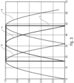
- FIG. 5 A progression of the results of the symbol reconstruction at different time offsets is shown Fig. 5
- the center represents the ideal time.
- the amplitude is plotted on the y-axis against the time offset (or alternatively, the timing error) in symbol lengths.
- the real part R and the imaginary part I are plotted.
- Fig. 5 shows that at the ideal time the influence of the neighboring symbols (i.e. the flanking symbols in the example of Fig. 2 ) is smallest. With increasing time offset, the influence of the neighboring symbols increases, ie in this example with MSK modulation, the amplitude of the imaginary part increases.
- the received symbol here the middle symbol
- the conjugate complex of the transmitted symbol i.e. the reference symbol or the corresponding symbol of the reference sequence
- phase offset is shown Fig. 6 for the Fig. 5 corresponding symbol over the time offset.
- the phase offset that is, the resulting phase error due to the time offset—is always positive.
- the magnitude depends on the magnitude of the time offset.
- the Fig. 7 shows the amplitude of the three symbols b, a, b versus time in sampling rates.
- the two flanking symbols b encompass the middle symbol a.
- no symbol crosstalk (ISI) occurs between the flanking symbols and the middle symbol.
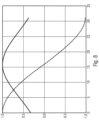
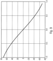
- the Fig. 8 shows the amplitude of the middle symbol after matched filtering as a function of the time offset.
- reception symbol is processed after matched filtering in the same way as for the Fig. 6 multiplied by the complex conjugate value of the transmit symbol, one obtains the phase offset between the reference symbol and the received symbol under consideration.
- the phase offset is shown Fig. 9 for the Fig. 8 considered mean symbol over the time offset. Compared to Fig. 6 The phase offset curve is no longer positive for all possible time offsets. For negative time offsets, the phase offset is positive, and for positive time offsets, it changes its sign and becomes negative.
- phase offset depends on the symbols that flank the symbol being evaluated.
- the symbols are selected in such a way that the phase errors resulting from a time offset when evaluating the individual symbols compensate each other when averaging over the affected symbols - whether from one signal or over several signals.
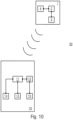
- the Fig. 10 shows a system 50 with a transmitter 1 and a receiver 10.
- the transmitter 1 has a signal generator 2 and a signal output device 3.
- the signal generator 2 generates the signals to be transmitted based on data that the transmitter 1 has to transmit.
- the data is, for example, sensor data or status data of the transmitter 1 itself.
- telegram splitting is used so that the data to be output is distributed across at least two signals, which can also be referred to as telegram fragments.
- the individual telegram fragments each have a pilot sequence provided by the signal generator 2.
- the provision for the individual signals to be transmitted consists in the signal generator 2 accessing a data memory 4 in which the data for the appropriate pilot sequence is stored.
- the signal output device 3 transmits the individual telegram fragments.
- the individual telegram fragments are received and processed by receiver 10. Synchronization between transmitter 1 and receiver 10 is required for processing, for which purpose synchronization device 11 is provided.
- the pilot sequences with their pilot symbols serve for synchronization.
- Time synchronization is required. This refers to the estimation of the temporal position of the received signal and the associated optimal time for sampling the signal.
- the synchronization device 11 is connected to a sampling device 13.
- the sampling times cannot generally be influenced. Rather, the time is necessary to reconstruct the symbols from the usually oversampled signal or, if necessary, to perform an interpolation.
- further synchronization relates to frequency.
- Relevant factors here are the carrier frequency at which the signals are transmitted by transmitter 1 and the center frequency of filter device 14, which is used to filter the received signals.
- the signals are frequency-shifted before the filter after reception. The difference between the two frequencies is referred to as the frequency offset.
- filter device 14 is connected to synchronization device 11.
- frequency synchronization is followed by phase synchronization.
- the signal evaluation device 12 which transmits the corresponding synchronization data to the synchronization device 11, is described in more detail below.
- each pilot symbol of the pilot sequence of the received signal is compared with the corresponding reference symbol of a reference sequence.
- the reference sequence is identical to the pilot sequence used by transmitter 1 to generate the signal or inserted into the signal. Once a phase value has been determined for each pilot symbol, a total value is subsequently generated, e.g., by averaging the individual phase values.
- the reference sequences are stored in a data memory 15.
- the errors in the phase value are also averaged. Therefore, the average phase error for all pilot symbols is used for synchronization.
- the dependence of the phase error of a symbol on the preceding and subsequent symbols is taken into account, based on the above investigations.
- the symbols are therefore selected in such a way that the phase errors just compensate for each other due to time offsets when averaging the individual phase values generated for each symbol.
- pilot symbols are transmitted one after the other, the previous and the following symbol (i.e. the symbols that are used in the example of the Fig. 2 directly flanking a middle symbol or symbol considered for evaluation), or these are known to the receiver.
- a second symbol is transmitted that has the opposite error (with the same time offset). This applies here to the symbols of a signal carrying a pilot sequence.
- phase errors are averaged over the partial pilot sequences of several signals, which are in particular telegram fragments.
- the length of the pilot sequence is a multiple of the length of two, so that an even number of additions is created for the averaging.
- a positive phase offset is generated in the event of a time offset, which applies to both positive and negative time offsets.
- a symbol must also be transmitted in which the error at the same level indicates a negative phase error.
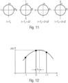
- the Fig. 11 shows the mapping rule for MSK modulation. It shows the possible constellation points of MSK with precoding (also known as non-diff MSK in MATLAB).
- the symbols to be transmitted are divided into groups of four symbols, with the first symbol being transmitted at time T0 . Accordingly, at time T0, the constellation point +1 + 0j is chosen for a binary zero and the constellation point -1 + 0j is chosen for a binary one. The time T0 + ⁇ T is chosen for the following symbol. The constellation points are thus 0 + 1j (binary one) and 0 - 1j (binary zero). The constellation points are calculated in the same way for the two following times. After four symbols have been mapped to the constellation points, the process starts again at time T0 .
- the pilot sequence with which transmitter 1 transmits the signals is defined in such a way that the sum of the phase offsets is minimized in the case of a time shift.
- the zeros and ones are the pilot sequence bits, which, through appropriate mapping, result in the symbols of the pilot sequence or the partial pilot sequence.
- a transmitter 1 is designed to transmit at least one signal with a pilot sequence having a plurality of pilot symbols, wherein the transmitter 1 has a signal generator 2, wherein the signal generator 2 provides the pilot sequence, wherein the signal generator 2 provides the pilot sequence in such a way that the pilot sequence has at least two symbol groups, each with at least two pilot symbols, and wherein the symbol groups, when evaluating a signal received by a receiver 10 as a result of the transmission of the signal, generate phase errors with regard to a phase that are dependent on a time offset between a reference time of the transmission of the signal by the transmitter 1 and a value assumed and/or estimated for the evaluation for the reference time, which phase errors essentially compensate for one another during the evaluation across the symbol groups.
- At least one symbol group consists of a central symbol and two flanking symbols.
- the transmitter 1 outputs data to be output by at least two telegram fragments which the transmitter 1 transmits as individual signals and which are shorter than a single telegram comprising the data as a whole, and at least one telegram fragment comprises the pilot sequence generated by the signal generator 2.
- a transmitter 1 is designed to transmit at least two signals, each having a partial pilot sequence comprising a plurality of pilot symbols, wherein the transmitter 1 has a signal generator 2, wherein the signal generator 2 provides the partial pilot sequence, wherein the signal generator 2 provides the partial pilot sequences of the signals in such a way that the partial pilot sequences each have at least one symbol group with at least two pilot symbols, and wherein the symbol groups of the signals, when evaluating signals received by a receiver 10 as a result of the transmission of the signals, generate phase errors with regard to a phase dependent on a time offset between a reference time of the respective transmission of a signal and a value assumed and/or estimated for the evaluation for the reference time, which phase errors essentially compensate for one another during the evaluation together across the signals.
- At least one partial pilot sequence comprises at least two symbol groups and the symbol groups partially overlap.
- At least one symbol group consists of a central symbol and two flanking symbols.
- the transmitter 1 transmits signals having partial pilot sequences resulting from MSK modulation or GMSK modulation.
- a seventeenth aspect relates to a method for transmitting signals, wherein the signals are transmitted with a pilot sequence each having a plurality of pilot sequence symbols, wherein the pilot sequences are provided in such a way that the pilot sequences each have at least two symbol groups each having at least two pilot symbols, and wherein the symbol groups, when evaluating a signal received by a receiver 10 as a result of the transmission of the signal with regard to a phase, generate phase errors which are dependent on a time offset between a reference time of transmission of the signal and a value assumed and/or estimated for the evaluation for the reference time, which phase errors essentially compensate for one another during the evaluation across the symbol groups.
- An eighteenth aspect relates to a method for transmitting signals, wherein at least two signals are transmitted, each having a partial pilot sequence comprising a plurality of pilot sequence symbols, wherein the partial pilot sequences are provided in such a way that the partial pilot sequence each has at least one symbol group each having at least two pilot symbols, and wherein the symbol groups of the signals, when evaluating signals received by a receiver 10 as a result of the transmission of the signals, generate phase errors with respect to a phase dependent on a time offset between a reference time of the respective transmission of a signal and a value assumed and/or estimated for the evaluation for the reference time, which phase errors essentially compensate for one another during the evaluation together across the signals.
- a nineteenth aspect relates to a computer program comprising program code for carrying out the method according to the seventeenth or eighteenth aspect.
- a twentieth aspect relates to a receiver 10, wherein the receiver 10 is designed to receive at least one signal transmitted by a transmitter 1, wherein the receiver 10 has a synchronization device 11, wherein the synchronization device 11 is designed to synchronize the receiver 10 with the transmitter 1 based on the received signal, wherein the receiver 10 has a signal evaluation device 12, wherein the signal evaluation device 12 determines data for the synchronization from the received signal and transfers it to the synchronization device 11 for the synchronization, wherein the signal evaluation device 12, when evaluating a pilot sequence or a partial pilot sequence of a received signal, determines a time offset between a reference time of a transmission of the signal by the transmitter 1 and a value assumed and/or estimated for the evaluation for the reference time, and wherein the signal evaluation device 12 accesses symbols of a reference sequence adapted to the time offset for the further evaluation of the pilot sequence, or wherein the signal evaluation device 12 accesses symbols of a part of a reference sequence adapted to the time offset or of a part of a reference sequence adapted to
- the signal evaluation device 12 carries out the adaptation of the reference sequence or the part of the reference sequence in that the signal evaluation device 12 shifts a known reference sequence or a part of a known reference sequence in time by the determined time offset.
- the signal evaluation device 12 adapts the reference sequence or the part of the reference sequence by the signal evaluation device 12 accessing a data memory 15 with correspondingly stored reference sequences or parts of reference sequences.
- the receiver 10 comprises a filter device 14 and a sampling device 13.
- a twenty-fourth aspect relates to a method for synchronizing a receiver 10 with a transmitter 1, wherein at least one signal transmitted by the transmitter 1 is received by the receiver 10, wherein, starting from a pilot sequence or a partial pilot sequence of the received signal, a synchronization of the receiver 10 with the transmitter 1 is carried out, wherein a time offset between a reference time of a transmission of the signal by the transmitter 1 and a value assumed and/or estimated for the reference time is determined and wherein a pilot sequence of the received signal is evaluated with symbols of a reference sequence adapted to the time offset, or wherein a partial pilot sequence of the received signal is evaluated with symbols of a part of a reference sequence adapted to the time offset or with symbols of a part of a reference sequence adapted to the time offset.
- a twenty-fifth aspect relates to a receiver 10, wherein the receiver 10 is configured to receive at least one signal transmitted by a transmitter 1, wherein the receiver 10 has a synchronization device 11, wherein the synchronization device 11 is configured to synchronize the receiver 10 with the transmitter 1 based on the received signal, wherein the receiver 10 has a signal evaluation device 12, wherein the signal evaluation device 12 determines data for the synchronization from the received signal and transfers it to the synchronization device 11 for the synchronization, wherein the receiver 10 is configured to receive a plurality of telegram fragments transmitted by the transmitter 1, wherein the telegram fragments each have a partial pilot sequence, wherein the telegram fragments complement each other to form a telegram containing data transmitted by the transmitter 1, wherein the telegram fragments are shorter than a single Telegram comprising the transmitted data, wherein the partial pilot sequences complement one another to form a pilot sequence, and wherein the signal evaluation device 12, starting from the partial pilot sequences and using the DFT method, determines a value for
- the signal evaluation device 12 determines the values of the decision variables d i [k] for each partial pilot sequence by the signal evaluation device 12 forming, for a plurality of frequencies of a complex exponential oscillation, referred to as frequency hypotheses, multiplication values of a multiplication of sample values of the respective partial pilot sequence with conjugate complex values of an equal number of reference symbols of a known reference sequence and with sample values of the complex exponential oscillation and summing the multiplication values.
- the signal evaluation device 12 combines the values of the decision variables d i [k] determined for the partial pilot sequences together for the partial pilot sequences by the signal evaluation device 12 adding the absolute values of the decision variables d i [k].
- the signal evaluation device 12 combines the values of the decision variables d i [k] determined for the partial pilot sequences together for the partial pilot sequences by the signal evaluation device 12 forming a sum of the absolute values of a real part and an imaginary part of the values of the decision variables d i [k].
- the signal evaluation device 12 combines the values of the decision variables d i [k] determined for the partial pilot sequences together for the partial pilot sequences by the signal evaluation device 12 summing the absolute value squares of the values of the decision variables d i [k].
- the signal evaluation device 12 combines the values of the decision variables d i [k] determined for the partial pilot sequences together for the partial pilot sequences coherently, taking into account the absolute value and phase of the values of the decision variables d i [k].
- the signal evaluation device 12 combines the determined values of the decision variables d i [k] with one another, taking into account weighting factors.
- the signal evaluation device 12 combines the determined values of the decision variables d i [k] with one another, taking into account weighting factors relating to the partial pilot sequences.
- the signal evaluation device 12 determines the weighting factors based on a signal-to-noise ratio of the respective telegram fragment.
- the signal evaluation device 12 determines the weighting factors as proportional to a square root of the signal-to-noise ratio.
- the signal evaluation device 12 obtains the maximum value based on the determination of the maximum value and a positive comparison of the maximum value with a decision threshold.
- the receiver 10 is configured to receive a plurality of telegram fragments transmitted by the transmitter 1, wherein the telegram fragments each have a partial pilot sequence, wherein the telegram fragments complement each other to form a telegram containing data transmitted by the transmitter 1, wherein the telegram fragments are shorter than a single telegram containing the transmitted data, wherein the partial pilot sequences complement each other to form a pilot sequence, and wherein the signal evaluation device 12, based on the partial pilot sequences and using the DFT method, determines a value for a frequency difference between a transmission frequency of the transmitter 1 and a reception frequency of the receiver 10, in that the signal evaluation device 12 determines values of decision variables d i [k] for each partial pilot sequence, the determined values of the decision variables d i [k] are combined with one another via the partial pilot sequences and a maximum value is determined using the combined values, where
- the signal evaluation device 12 generates the frequency estimate from the maximum value and two adjacent values, wherein the two adjacent values precede and follow the determined maximum value with respect to the frequency variable.
- the signal evaluation device 12 determines a polynomial for the maximum value and the two adjacent values, and the signal evaluation device 12 determines the frequency estimate from an extreme value associated with the polynomial.
- the signal evaluation device 12 performs the interpolation with a second-degree polynomial.
- the signal evaluation device 12 determines the time estimate and uses the same for a renewed determination of the frequency difference by the signal evaluation device 12 using samples of the respective partial pilot sequences shifted by the time estimate when a renewed determination of the values of the decision variables d i [k] or by shifting reference symbols of a reference sequence in time by the time estimate.
- the signal evaluation device 12 interpolates the sample values of the respective partial pilot sequences for the renewed determination of the frequency difference.
- the signal evaluation device 12 After the renewed determination of the frequency difference, carries out a frequency estimation for the frequency difference in that the signal evaluation device 12 determines a frequency estimate based on a maximum value obtained by determining the maximum value and a positive comparison with the decision threshold and at least one value adjacent to a frequency variable.
- a fifty-fourth aspect relates to a method for synchronizing a receiver 10 with a transmitter 1, wherein at least one signal transmitted by the transmitter 1 is received by the receiver 10, wherein, starting from a pilot sequence or a partial pilot sequence of the received signal, a synchronization of the receiver 10 with the transmitter 1 is carried out, wherein the receiver 10 receives a plurality of telegram fragments transmitted by the transmitter 1, wherein the telegram fragments each have a partial pilot sequence, wherein the telegram fragments complement each other to form a telegram that contains data transmitted by the transmitter 1, wherein the telegram fragments are shorter than the telegram, wherein the partial pilot sequences complement each other to form a pilot sequence, wherein, starting from the partial pilot sequences, the receiver 10 is synchronized with the transmitter 1 wherein, starting from the partial pilot sequences and using the DFT method, a value for a frequency difference between a transmission frequency of the transmitter 1 and a reception frequency of the receiver 10 is determined by determining values of decision variables d i
- a fifty-fifth aspect relates to a computer program having program code for performing the method according to one of the twenty-fourth or fifty-fourth aspects.
- aspects have been described in connection with a device, it should be understood that these aspects also represent a description of the corresponding method, so that a block or component of a device can also be understood as a corresponding method step or as a feature of a method step. Analogously, aspects described in connection with or as a method step also represent a description of a corresponding block, detail, or feature of a corresponding device.
- Some or all of the method steps may be performed by (or using) a hardware apparatus, such as a microprocessor, a programmable computer, or an electronic circuit. In some embodiments, some or more of the key method steps may be performed by such an apparatus.
- embodiments of the invention may be implemented in hardware or in software, or at least partially in hardware or at least partially in software.
- the implementation may be carried out using a digital storage medium, for example a floppy disk, a DVD, a Blu-ray disc, a CD, a ROM, a PROM, an EPROM, an EEPROM, or a FLASH memory, a hard disk, or other magnetic or optical storage device on which electronically readable control signals are stored that can interact or interact with a programmable computer system such that the respective method is carried out. Therefore, the digital storage medium may be computer-readable.
- Some embodiments according to the invention thus comprise a data carrier having electronically readable control signals capable of interacting with a programmable computer system such that one of the methods described herein is carried out.
- embodiments of the present invention may be implemented as a computer program product having program code, wherein the program code is operable to perform one of the methods when the computer program product is run on a computer.
- the program code can, for example, also be stored on a machine-readable medium.
- embodiments include the computer program for performing one of the methods described herein, wherein the computer program is stored on a machine-readable medium.
- one embodiment of the method according to the invention is thus a computer program that has program code for performing one of the methods described herein when the computer program is executed on a computer.
- a further embodiment of the method according to the invention is thus a data carrier (or a digital storage medium or a computer-readable medium) on which the computer program for performing one of the methods described herein is recorded.
- the data carrier or the digital storage medium or the computer-readable medium is typically tangible and/or non-transitory.
- a further embodiment of the method according to the invention is thus a data stream or a sequence of signals that represents the computer program for carrying out one of the methods described herein.
- the data stream or the sequence of signals can be configured, for example, to be transferred via a data communication connection, for example via the Internet.
- a further embodiment comprises a processing device, for example a computer or a programmable logic device, which is configured or adapted to carry out one of the methods described herein.
- a processing device for example a computer or a programmable logic device, which is configured or adapted to carry out one of the methods described herein.
- a further embodiment comprises a computer on which the computer program for performing one of the methods described herein is installed.
- a further embodiment according to the invention comprises a device or a system designed to transmit a computer program for performing at least one of the methods described herein to a recipient.
- the transmission can be electronic or optical, for example.
- the recipient can be, for example, a computer, a mobile device, a storage device, or a similar device.
- the device or system can, for example, comprise a file server for transmitting the computer program to the recipient.
- a programmable logic device e.g., a field-programmable gate array, an FPGA
- a field-programmable gate array may interact with a microprocessor to perform any of the methods described herein.
- the methods are performed by any hardware device. This may be general-purpose hardware such as a computer processor (CPU) or method-specific hardware such as an ASIC or, for example, a microprocessor, e.g., in the form of an ARM architecture.
Landscapes
- Engineering & Computer Science (AREA)
- Computer Networks & Wireless Communication (AREA)
- Signal Processing (AREA)
- Digital Transmission Methods That Use Modulated Carrier Waves (AREA)
- Synchronisation In Digital Transmission Systems (AREA)
- Mobile Radio Communication Systems (AREA)
- Radar Systems Or Details Thereof (AREA)
- Cable Transmission Systems, Equalization Of Radio And Reduction Of Echo (AREA)
Applications Claiming Priority (3)
| Application Number | Priority Date | Filing Date | Title |
|---|---|---|---|
| DE102017206259.2A DE102017206259B3 (de) | 2017-04-11 | 2017-04-11 | Sender und empfänger und entsprechende verfahren |
| PCT/EP2018/025099 WO2018188809A1 (de) | 2017-04-11 | 2018-04-09 | Sender und empfänger und entsprechende verfahren |
| EP18718110.2A EP3610617B1 (de) | 2017-04-11 | 2018-04-09 | Sender und empfänger und entsprechende verfahren |
Related Parent Applications (2)
| Application Number | Title | Priority Date | Filing Date |
|---|---|---|---|
| EP18718110.2A Division-Into EP3610617B1 (de) | 2017-04-11 | 2018-04-09 | Sender und empfänger und entsprechende verfahren |
| EP18718110.2A Division EP3610617B1 (de) | 2017-04-11 | 2018-04-09 | Sender und empfänger und entsprechende verfahren |
Publications (2)
| Publication Number | Publication Date |
|---|---|
| EP3876491A1 EP3876491A1 (de) | 2021-09-08 |
| EP3876491B1 true EP3876491B1 (de) | 2025-05-07 |
Family
ID=62002109
Family Applications (2)
| Application Number | Title | Priority Date | Filing Date |
|---|---|---|---|
| EP21170876.3A Active EP3876491B1 (de) | 2017-04-11 | 2018-04-09 | Sender und empfänger und entsprechende verfahren |
| EP18718110.2A Active EP3610617B1 (de) | 2017-04-11 | 2018-04-09 | Sender und empfänger und entsprechende verfahren |
Family Applications After (1)
| Application Number | Title | Priority Date | Filing Date |
|---|---|---|---|
| EP18718110.2A Active EP3610617B1 (de) | 2017-04-11 | 2018-04-09 | Sender und empfänger und entsprechende verfahren |
Country Status (13)
| Country | Link |
|---|---|
| US (1) | US10868705B2 (pl) |
| EP (2) | EP3876491B1 (pl) |
| JP (2) | JP2020517177A (pl) |
| KR (1) | KR102341877B1 (pl) |
| CN (1) | CN110832817B (pl) |
| CA (1) | CA3059522C (pl) |
| DE (1) | DE102017206259B3 (pl) |
| DK (1) | DK3610617T3 (pl) |
| MX (1) | MX2019012204A (pl) |
| MY (1) | MY204522A (pl) |
| PL (1) | PL3610617T3 (pl) |
| RU (1) | RU2733532C1 (pl) |
| WO (1) | WO2018188809A1 (pl) |
Families Citing this family (8)
| Publication number | Priority date | Publication date | Assignee | Title |
|---|---|---|---|---|
| DE102017206236A1 (de) * | 2017-04-11 | 2018-10-11 | Fraunhofer-Gesellschaft zur Förderung der angewandten Forschung e.V. | Spezifische hoppingmuster für telegram-splitting |
| DE102018218730A1 (de) * | 2018-10-31 | 2020-04-30 | Diehl Metering Gmbh | Detektion einer Pilotsequenz auf einfachen Rechnern |
| CN111901891B (zh) * | 2020-01-16 | 2025-10-31 | 中兴通讯股份有限公司 | 数据处理方法、装置、第一通信节点和第二通信节点 |
| CN111896078B (zh) * | 2020-07-09 | 2022-05-13 | 合肥联睿微电子科技有限公司 | 一种基于蓝牙通讯的校表方法 |
| CN111970087B (zh) * | 2020-07-30 | 2022-10-28 | 西南电子技术研究所(中国电子科技集团公司第十研究所) | Gmsk调制的硬件实现方法 |
| CN112671528B (zh) * | 2020-12-03 | 2023-07-18 | 东南大学 | 一种基于dft的符号跳变单频复指数信号频率估计方法 |
| CN112436905B (zh) * | 2021-01-27 | 2021-04-09 | 西南交通大学 | 一种通信雷达联合系统 |
| US11870627B2 (en) * | 2021-08-18 | 2024-01-09 | Qualcomm Incorporated | Guard interval-based waveform with data part and tail part |
Family Cites Families (21)
| Publication number | Priority date | Publication date | Assignee | Title |
|---|---|---|---|---|
| CN1148910C (zh) * | 2001-02-28 | 2004-05-05 | 上海大唐移动通信设备有限公司 | 在通信系统中校正信号的信噪比估计值的方法和装置 |
| JP3761887B2 (ja) * | 2004-01-15 | 2006-03-29 | 日本無線株式会社 | 既知信号区間検出回路 |
| US7742533B2 (en) * | 2004-03-12 | 2010-06-22 | Kabushiki Kaisha Toshiba | OFDM signal transmission method and apparatus |
| KR100770924B1 (ko) * | 2005-02-04 | 2007-10-26 | 삼성전자주식회사 | 무선 통신 시스템에서 주파수 오차 보상 장치 및 방법 |
| JP4526977B2 (ja) * | 2005-03-02 | 2010-08-18 | 株式会社エヌ・ティ・ティ・ドコモ | 送信機および送信制御方法 |
| CN1333533C (zh) * | 2005-05-16 | 2007-08-22 | 北京北方烽火科技有限公司 | 直接序列扩频移动通信系统的频率补偿方法 |
| US7720164B2 (en) * | 2007-02-26 | 2010-05-18 | Telefonaktiebolaget L M Ericsson (Publ) | Transmission scheme for uplink access in a FDMA system |
| IL203785A (en) | 2007-09-12 | 2014-07-31 | Qualcomm Inc | Devices to increase capacitance and methods for wireless communication |
| ATE539581T1 (de) * | 2008-06-23 | 2012-01-15 | Greenpeak Technologies N V | Endknoten und netzwerkkoordinator, die ein auf csma basierendes protokoll verwenden |
| WO2010119332A1 (en) * | 2009-04-16 | 2010-10-21 | Panoramic Power Ltd. | Apparatus and methods thereof for power consumption measurement at circuit breaker points |
| JP2011101131A (ja) * | 2009-11-05 | 2011-05-19 | Nec Corp | バースト通信用変調装置、復調装置、変調および復調方法ならびに通信システム |
| EP2545652B1 (en) * | 2010-03-12 | 2018-02-28 | Sunrise Micro Devices Inc. | Power efficient communications |
| US8718169B2 (en) | 2010-06-15 | 2014-05-06 | Qualcomm Incorporated | Using a field format on a communication device |
| US8576743B2 (en) * | 2010-12-28 | 2013-11-05 | Qualcomm Incorporated | Apparatus and methods for estimating an unknown frequency error of a tone signal |
| JP5601205B2 (ja) * | 2011-01-07 | 2014-10-08 | 富士通株式会社 | 光受信器および光通信システム |
| US20130230120A1 (en) * | 2011-08-29 | 2013-09-05 | Qualcomm Incorporated | Apparatus and methods for long and short training sequences for a fast fourier transform |
| DE102011082098B4 (de) | 2011-09-02 | 2014-04-10 | Fraunhofer-Gesellschaft zur Förderung der angewandten Forschung e.V. | Batteriebetriebene stationäre Sensoranordnung mit unidirektionaler Datenübertragung |
| US8824501B2 (en) * | 2011-09-16 | 2014-09-02 | Alcatel Lucent | Performance enhancement through optical variants |
| EP2914039A1 (de) | 2014-02-26 | 2015-09-02 | Fraunhofer-Gesellschaft zur Förderung der angewandten Forschung e.V. | Datensendeanordnung, Datenempfänger und Verfahren zum Betreiben derselben |
| WO2016165080A1 (zh) * | 2015-04-15 | 2016-10-20 | 华为技术有限公司 | 参考信号发送与接收方法及装置 |
| ES2836528T3 (es) | 2016-03-31 | 2021-06-25 | Fraunhofer Ges Forschung | Preámbulo optimizado y procedimiento para detección robusta de paquetes de interferencia para aplicaciones de telemetría |
-
2017
- 2017-04-11 DE DE102017206259.2A patent/DE102017206259B3/de active Active
-
2018
- 2018-04-09 MX MX2019012204A patent/MX2019012204A/es unknown
- 2018-04-09 MY MYPI2019005852A patent/MY204522A/en unknown
- 2018-04-09 JP JP2019555767A patent/JP2020517177A/ja active Pending
- 2018-04-09 CN CN201880038525.0A patent/CN110832817B/zh active Active
- 2018-04-09 DK DK18718110.2T patent/DK3610617T3/da active
- 2018-04-09 PL PL18718110T patent/PL3610617T3/pl unknown
- 2018-04-09 KR KR1020197033260A patent/KR102341877B1/ko active Active
- 2018-04-09 EP EP21170876.3A patent/EP3876491B1/de active Active
- 2018-04-09 WO PCT/EP2018/025099 patent/WO2018188809A1/de not_active Ceased
- 2018-04-09 EP EP18718110.2A patent/EP3610617B1/de active Active
- 2018-04-09 CA CA3059522A patent/CA3059522C/en active Active
- 2018-04-09 RU RU2019135847A patent/RU2733532C1/ru active
-
2019
- 2019-10-10 US US16/598,871 patent/US10868705B2/en active Active
-
2022
- 2022-01-28 JP JP2022011809A patent/JP2022064954A/ja active Pending
Non-Patent Citations (1)
| Title |
|---|
| LUISE M ET AL: "CARRIER FREQUENCY RECOVERY IN ALL-DIGITAL MODEMS FOR BURST-MODE TRANSMISSIONS", IEEE TRANSACTIONS ON COMMUNICATIONS, IEEE SERVICE CENTER, PISCATAWAY, NJ. USA, vol. 43, no. 2/04, PART 02, 1 February 1995 (1995-02-01), pages 1169 - 1178, XP000502606, ISSN: 0090-6778, DOI: 10.1109/26.380149 * |
Also Published As
| Publication number | Publication date |
|---|---|
| KR102341877B1 (ko) | 2021-12-21 |
| US20200052952A1 (en) | 2020-02-13 |
| DE102017206259B3 (de) | 2018-07-12 |
| EP3610617B1 (de) | 2021-07-28 |
| CN110832817A (zh) | 2020-02-21 |
| MY204522A (en) | 2024-09-02 |
| JP2020517177A (ja) | 2020-06-11 |
| CA3059522A1 (en) | 2018-10-18 |
| MX2019012204A (es) | 2020-01-21 |
| KR20190140453A (ko) | 2019-12-19 |
| PL3610617T3 (pl) | 2022-01-03 |
| WO2018188809A1 (de) | 2018-10-18 |
| RU2733532C1 (ru) | 2020-10-05 |
| DK3610617T3 (da) | 2021-10-25 |
| CA3059522C (en) | 2021-12-14 |
| CN110832817B (zh) | 2022-06-03 |
| US10868705B2 (en) | 2020-12-15 |
| JP2022064954A (ja) | 2022-04-26 |
| EP3876491A1 (de) | 2021-09-08 |
| EP3610617A1 (de) | 2020-02-19 |
Similar Documents
| Publication | Publication Date | Title |
|---|---|---|
| EP3876491B1 (de) | Sender und empfänger und entsprechende verfahren | |
| DE102015107080B3 (de) | Verfahren und Vorrichtungen zur Kanalschätzung für Mobilsysteme ungenügender zyklischer Präfixlänge | |
| DE102018206162B3 (de) | Interferenzdetektion und Unterdrückung in nichtkoordinierten Systemen | |
| EP3610595B1 (de) | Sender und empfänger und entsprechende verfahren | |
| DE10112773B4 (de) | Verfahren zur Frequenz- und Zeit-Synchronisation eines OFDM-Empfängers | |
| DE602005003273T2 (de) | Verfahren zum Schätzen des Frequenzversatzes in einem Kommunikationssystem über einen Rayleigh-Fading-Kanal | |
| EP0829990B1 (de) | Verfahren zur Demodulation von höherstufigen MQAM-Signalen ohne Kenntnis der übertragenen Symbole | |
| DE102007023881A1 (de) | Verfahren und Vorrichtung zur Ermittlung einer unverkürzten Kanalimpulsantwort in einem OFDM-Übertragungssystem | |
| EP3756291B1 (de) | Empfänger und verfahren zum empfangen eines kombinationssignals unter verwendung getrennter inphase- und quadraturkomponente | |
| EP1313281B1 (de) | Verfahren und System zur Frequenzoffsetschätzung für Trägermodulierte digitale Kommunikationssysteme | |
| EP3756290B1 (de) | Empfänger, sender, verfahren und system zum empfangen und senden eines kombinationssignals | |
| EP3756320B1 (de) | Empfänger und verfahren zum empfangen eines kombinationssignals unter verwendung von wahrscheinlichkeitsdichtefunktionen | |
| DE10006520A1 (de) | Verfahren zur Schätzung von Kanalparametern von Funkkanälen eines W-CDMA-Mobilfunksystems | |
| DE60024328T2 (de) | Verfahren zur schätzung der symboltaktphase beim empfang von datensignalen | |
| EP1505786B1 (de) | Verfahren und Vorrichtung zum Schätzen der Frequenz und/oder der Phase einer digitalen Signalfolge | |
| EP1316182B1 (de) | Verbesserte kanalentzerrung für mobilfunkempfänger | |
| DE102017012191B4 (de) | Sender und Empfänger und entsprechende Verfahren | |
| DE102004059958A1 (de) | Vorrichtung und Verfahren zum Bestimmen eines Korrelationswertes | |
| DE102017012190A1 (de) | Sender und Empfänger und entsprechende Verfahren | |
| DE102018010283B3 (de) | Interferenzdetektion und Unterdrückung in nichtkoordinierten Systemen | |
| DE102018010284B3 (de) | Interferenzdetektion und Unterdrückung in nichtkoordinierten Systemen | |
| EP4199441A1 (de) | Empfänger zum empfangen eines kombinationssignals mit berücksichtigung einer inter-symbol-interferenz, verfahren zum empfangen eines kombinationssignals und computerprogramm | |
| DE102015008020B4 (de) | Digitale Störgrößenmodulation zur Maximierung des erzielbaren Datendurchsatzes von Nachrichtenübertragungssystemen | |
| EP3994856B1 (de) | Empfänger zum empfangen eines kombinationssignals mit berücksichtigung einer inter-symbol-interferenz und niedriger komplexität, verfahren zum empfangen eines kombinationssignals und computerprogramm | |
| DE102017012226A1 (de) | Sender und Empfänger und entsprechende Verfahren |
Legal Events
| Date | Code | Title | Description |
|---|---|---|---|
| PUAI | Public reference made under article 153(3) epc to a published international application that has entered the european phase |
Free format text: ORIGINAL CODE: 0009012 |
|
| STAA | Information on the status of an ep patent application or granted ep patent |
Free format text: STATUS: THE APPLICATION HAS BEEN PUBLISHED |
|
| AC | Divisional application: reference to earlier application |
Ref document number: 3610617 Country of ref document: EP Kind code of ref document: P |
|
| AK | Designated contracting states |
Kind code of ref document: A1 Designated state(s): AL AT BE BG CH CY CZ DE DK EE ES FI FR GB GR HR HU IE IS IT LI LT LU LV MC MK MT NL NO PL PT RO RS SE SI SK SM TR |
|
| STAA | Information on the status of an ep patent application or granted ep patent |
Free format text: STATUS: REQUEST FOR EXAMINATION WAS MADE |
|
| 17P | Request for examination filed |
Effective date: 20220307 |
|
| RBV | Designated contracting states (corrected) |
Designated state(s): AL AT BE BG CH CY CZ DE DK EE ES FI FR GB GR HR HU IE IS IT LI LT LU LV MC MK MT NL NO PL PT RO RS SE SI SK SM TR |
|
| RAP3 | Party data changed (applicant data changed or rights of an application transferred) |
Owner name: FRIEDRICH-ALEXANDER-UNIVERSITAET ERLANGEN-NUERNBERG Owner name: FRAUNHOFER-GESELLSCHAFT ZUR FOERDERUNG DER ANGEWANDTEN FORSCHUNG E.V. |
|
| STAA | Information on the status of an ep patent application or granted ep patent |
Free format text: STATUS: EXAMINATION IS IN PROGRESS |
|
| 17Q | First examination report despatched |
Effective date: 20230201 |
|
| GRAP | Despatch of communication of intention to grant a patent |
Free format text: ORIGINAL CODE: EPIDOSNIGR1 |
|
| STAA | Information on the status of an ep patent application or granted ep patent |
Free format text: STATUS: GRANT OF PATENT IS INTENDED |
|
| INTG | Intention to grant announced |
Effective date: 20241205 |
|
| GRAS | Grant fee paid |
Free format text: ORIGINAL CODE: EPIDOSNIGR3 |
|
| GRAA | (expected) grant |
Free format text: ORIGINAL CODE: 0009210 |
|
| STAA | Information on the status of an ep patent application or granted ep patent |
Free format text: STATUS: THE PATENT HAS BEEN GRANTED |
|
| P01 | Opt-out of the competence of the unified patent court (upc) registered |
Free format text: CASE NUMBER: APP_13045/2025 Effective date: 20250317 |
|
| AC | Divisional application: reference to earlier application |
Ref document number: 3610617 Country of ref document: EP Kind code of ref document: P |
|
| AK | Designated contracting states |
Kind code of ref document: B1 Designated state(s): AL AT BE BG CH CY CZ DE DK EE ES FI FR GB GR HR HU IE IS IT LI LT LU LV MC MK MT NL NO PL PT RO RS SE SI SK SM TR |
|
| REG | Reference to a national code |
Ref country code: GB Ref legal event code: FG4D Free format text: NOT ENGLISH |
|
| REG | Reference to a national code |
Ref country code: CH Ref legal event code: EP |
|
| REG | Reference to a national code |
Ref country code: DE Ref legal event code: R096 Ref document number: 502018015805 Country of ref document: DE |
|
| REG | Reference to a national code |
Ref country code: IE Ref legal event code: FG4D Free format text: LANGUAGE OF EP DOCUMENT: GERMAN |
|
| REG | Reference to a national code |
Ref country code: DE Ref legal event code: R081 Ref document number: 502018015805 Country of ref document: DE Owner name: FRIEDRICH-ALEXANDER-UNIVERSITAET ERLANGEN-NUER, DE Free format text: FORMER OWNER: ANMELDERANGABEN UNKLAR / UNVOLLSTAENDIG, 80297 MUENCHEN, DE Ref country code: DE Ref legal event code: R081 Ref document number: 502018015805 Country of ref document: DE Owner name: FRAUNHOFER-GESELLSCHAFT ZUR FOERDERUNG DER ANG, DE Free format text: FORMER OWNER: ANMELDERANGABEN UNKLAR / UNVOLLSTAENDIG, 80297 MUENCHEN, DE |
|
| REG | Reference to a national code |
Ref country code: NL Ref legal event code: MP Effective date: 20250507 |
|
| PG25 | Lapsed in a contracting state [announced via postgrant information from national office to epo] |
Ref country code: PT Free format text: LAPSE BECAUSE OF FAILURE TO SUBMIT A TRANSLATION OF THE DESCRIPTION OR TO PAY THE FEE WITHIN THE PRESCRIBED TIME-LIMIT Effective date: 20250908 Ref country code: FI Free format text: LAPSE BECAUSE OF FAILURE TO SUBMIT A TRANSLATION OF THE DESCRIPTION OR TO PAY THE FEE WITHIN THE PRESCRIBED TIME-LIMIT Effective date: 20250507 Ref country code: ES Free format text: LAPSE BECAUSE OF FAILURE TO SUBMIT A TRANSLATION OF THE DESCRIPTION OR TO PAY THE FEE WITHIN THE PRESCRIBED TIME-LIMIT Effective date: 20250507 |
|
| REG | Reference to a national code |
Ref country code: LT Ref legal event code: MG9D |
|
| PG25 | Lapsed in a contracting state [announced via postgrant information from national office to epo] |
Ref country code: NO Free format text: LAPSE BECAUSE OF FAILURE TO SUBMIT A TRANSLATION OF THE DESCRIPTION OR TO PAY THE FEE WITHIN THE PRESCRIBED TIME-LIMIT Effective date: 20250807 Ref country code: GR Free format text: LAPSE BECAUSE OF FAILURE TO SUBMIT A TRANSLATION OF THE DESCRIPTION OR TO PAY THE FEE WITHIN THE PRESCRIBED TIME-LIMIT Effective date: 20250808 |
|
| PG25 | Lapsed in a contracting state [announced via postgrant information from national office to epo] |
Ref country code: NL Free format text: LAPSE BECAUSE OF FAILURE TO SUBMIT A TRANSLATION OF THE DESCRIPTION OR TO PAY THE FEE WITHIN THE PRESCRIBED TIME-LIMIT Effective date: 20250507 Ref country code: PL Free format text: LAPSE BECAUSE OF FAILURE TO SUBMIT A TRANSLATION OF THE DESCRIPTION OR TO PAY THE FEE WITHIN THE PRESCRIBED TIME-LIMIT Effective date: 20250507 |
|
| PG25 | Lapsed in a contracting state [announced via postgrant information from national office to epo] |
Ref country code: BG Free format text: LAPSE BECAUSE OF FAILURE TO SUBMIT A TRANSLATION OF THE DESCRIPTION OR TO PAY THE FEE WITHIN THE PRESCRIBED TIME-LIMIT Effective date: 20250507 |
|
| PG25 | Lapsed in a contracting state [announced via postgrant information from national office to epo] |
Ref country code: HR Free format text: LAPSE BECAUSE OF FAILURE TO SUBMIT A TRANSLATION OF THE DESCRIPTION OR TO PAY THE FEE WITHIN THE PRESCRIBED TIME-LIMIT Effective date: 20250507 |
|
| PG25 | Lapsed in a contracting state [announced via postgrant information from national office to epo] |
Ref country code: RS Free format text: LAPSE BECAUSE OF FAILURE TO SUBMIT A TRANSLATION OF THE DESCRIPTION OR TO PAY THE FEE WITHIN THE PRESCRIBED TIME-LIMIT Effective date: 20250807 |
|
| PG25 | Lapsed in a contracting state [announced via postgrant information from national office to epo] |
Ref country code: IS Free format text: LAPSE BECAUSE OF FAILURE TO SUBMIT A TRANSLATION OF THE DESCRIPTION OR TO PAY THE FEE WITHIN THE PRESCRIBED TIME-LIMIT Effective date: 20250907 |
|
| PG25 | Lapsed in a contracting state [announced via postgrant information from national office to epo] |
Ref country code: LV Free format text: LAPSE BECAUSE OF FAILURE TO SUBMIT A TRANSLATION OF THE DESCRIPTION OR TO PAY THE FEE WITHIN THE PRESCRIBED TIME-LIMIT Effective date: 20250507 |
|
| PG25 | Lapsed in a contracting state [announced via postgrant information from national office to epo] |
Ref country code: SM Free format text: LAPSE BECAUSE OF FAILURE TO SUBMIT A TRANSLATION OF THE DESCRIPTION OR TO PAY THE FEE WITHIN THE PRESCRIBED TIME-LIMIT Effective date: 20250507 Ref country code: DK Free format text: LAPSE BECAUSE OF FAILURE TO SUBMIT A TRANSLATION OF THE DESCRIPTION OR TO PAY THE FEE WITHIN THE PRESCRIBED TIME-LIMIT Effective date: 20250507 |
|
| PG25 | Lapsed in a contracting state [announced via postgrant information from national office to epo] |
Ref country code: CZ Free format text: LAPSE BECAUSE OF FAILURE TO SUBMIT A TRANSLATION OF THE DESCRIPTION OR TO PAY THE FEE WITHIN THE PRESCRIBED TIME-LIMIT Effective date: 20250507 |
|
| PG25 | Lapsed in a contracting state [announced via postgrant information from national office to epo] |
Ref country code: EE Free format text: LAPSE BECAUSE OF FAILURE TO SUBMIT A TRANSLATION OF THE DESCRIPTION OR TO PAY THE FEE WITHIN THE PRESCRIBED TIME-LIMIT Effective date: 20250507 |
|
| PG25 | Lapsed in a contracting state [announced via postgrant information from national office to epo] |
Ref country code: RO Free format text: LAPSE BECAUSE OF FAILURE TO SUBMIT A TRANSLATION OF THE DESCRIPTION OR TO PAY THE FEE WITHIN THE PRESCRIBED TIME-LIMIT Effective date: 20250507 Ref country code: SK Free format text: LAPSE BECAUSE OF FAILURE TO SUBMIT A TRANSLATION OF THE DESCRIPTION OR TO PAY THE FEE WITHIN THE PRESCRIBED TIME-LIMIT Effective date: 20250507 |
|
| PG25 | Lapsed in a contracting state [announced via postgrant information from national office to epo] |
Ref country code: IT Free format text: LAPSE BECAUSE OF FAILURE TO SUBMIT A TRANSLATION OF THE DESCRIPTION OR TO PAY THE FEE WITHIN THE PRESCRIBED TIME-LIMIT Effective date: 20250507 |
|
| REG | Reference to a national code |
Ref country code: DE Ref legal event code: R097 Ref document number: 502018015805 Country of ref document: DE |
|
| PLBE | No opposition filed within time limit |
Free format text: ORIGINAL CODE: 0009261 |
|
| STAA | Information on the status of an ep patent application or granted ep patent |
Free format text: STATUS: NO OPPOSITION FILED WITHIN TIME LIMIT |
|
| REG | Reference to a national code |
Ref country code: CH Ref legal event code: L10 Free format text: ST27 STATUS EVENT CODE: U-0-0-L10-L00 (AS PROVIDED BY THE NATIONAL OFFICE) Effective date: 20260318 |