EP3875715B1 - Tür- oder fensterschloss mit verdeckbarem griff - Google Patents
Tür- oder fensterschloss mit verdeckbarem griff Download PDFInfo
- Publication number
- EP3875715B1 EP3875715B1 EP20853593.0A EP20853593A EP3875715B1 EP 3875715 B1 EP3875715 B1 EP 3875715B1 EP 20853593 A EP20853593 A EP 20853593A EP 3875715 B1 EP3875715 B1 EP 3875715B1
- Authority
- EP
- European Patent Office
- Prior art keywords
- handle
- cavity
- adjusting
- rotary
- lock
- Prior art date
- Legal status (The legal status is an assumption and is not a legal conclusion. Google has not performed a legal analysis and makes no representation as to the accuracy of the status listed.)
- Active
Links
Images


Classifications
-
- E—FIXED CONSTRUCTIONS
- E05—LOCKS; KEYS; WINDOW OR DOOR FITTINGS; SAFES
- E05B—LOCKS; ACCESSORIES THEREFOR; HANDCUFFS
- E05B3/00—Fastening knobs or handles to lock or latch parts
-
- E—FIXED CONSTRUCTIONS
- E05—LOCKS; KEYS; WINDOW OR DOOR FITTINGS; SAFES
- E05C—BOLTS OR FASTENING DEVICES FOR WINGS, SPECIALLY FOR DOORS OR WINDOWS
- E05C3/00—Fastening devices with bolts moving pivotally or rotatively
- E05C3/02—Fastening devices with bolts moving pivotally or rotatively without latching action
- E05C3/04—Fastening devices with bolts moving pivotally or rotatively without latching action with operating handle or equivalent member rigid with the bolt
- E05C3/041—Fastening devices with bolts moving pivotally or rotatively without latching action with operating handle or equivalent member rigid with the bolt rotating about an axis perpendicular to the surface on which the fastener is mounted
- E05C3/042—Fastening devices with bolts moving pivotally or rotatively without latching action with operating handle or equivalent member rigid with the bolt rotating about an axis perpendicular to the surface on which the fastener is mounted the handle being at one side, the bolt at the other side or inside the wing
-
- E—FIXED CONSTRUCTIONS
- E05—LOCKS; KEYS; WINDOW OR DOOR FITTINGS; SAFES
- E05B—LOCKS; ACCESSORIES THEREFOR; HANDCUFFS
- E05B13/00—Devices preventing the key or the handle or both from being used
- E05B13/10—Devices preventing the key or the handle or both from being used formed by a lock arranged in the handle
- E05B13/106—Devices preventing the key or the handle or both from being used formed by a lock arranged in the handle for handles pivoted about an axis perpendicular to the wing
- E05B13/108—Devices preventing the key or the handle or both from being used formed by a lock arranged in the handle for handles pivoted about an axis perpendicular to the wing the lock coaxial with spindle
-
- E—FIXED CONSTRUCTIONS
- E05—LOCKS; KEYS; WINDOW OR DOOR FITTINGS; SAFES
- E05B—LOCKS; ACCESSORIES THEREFOR; HANDCUFFS
- E05B15/00—Other details of locks; Parts for engagement by bolts of fastening devices
-
- E—FIXED CONSTRUCTIONS
- E05—LOCKS; KEYS; WINDOW OR DOOR FITTINGS; SAFES
- E05B—LOCKS; ACCESSORIES THEREFOR; HANDCUFFS
- E05B15/00—Other details of locks; Parts for engagement by bolts of fastening devices
- E05B15/10—Bolts of locks or night latches
-
- E—FIXED CONSTRUCTIONS
- E05—LOCKS; KEYS; WINDOW OR DOOR FITTINGS; SAFES
- E05B—LOCKS; ACCESSORIES THEREFOR; HANDCUFFS
- E05B5/00—Handles completely let into the surface of the wing
- E05B5/003—Pop-out handles, e.g. sliding outwardly before rotation
Definitions
- the present disclosure pertains to the field of locks, and in particular relates to a door or window lock with a concealable handle.
- a door lock is a device used for locking a door to prevent others from opening the door.
- door locks There are many types of door locks. Different door locks are required in various occasions.
- the currently commercially available door locks basically have handles.
- the handle functions as a point on which a force acts when the user wants to open the door, so that the door can be opened by twisting the handle.
- such handle has some problems because it is exposed to the outside.
- the handle is often easily damaged by external impact, or the surface of the handle is scratched to adversely affect the overall appearance, or even the handle may fall off due to an excessive external force or a problem occurs in the connection between the handle and the door lock, so that the door lock cannot be opened by the handle.
- children running and playing, and people such as those lowered their heads to pick up things have often collided with the handles, which may cause some physiological harm to people who are not aware of protecting themselves.
- An object of the present invention is to propose a new technical solution for a door or window lock with a concealable handle, in order to ameliorate the above disadvantages of the prior art.
- a door or window lock with a concealable handle comprises a handle component, a latch component, and a housing.
- the handle component includes a rotary handle and a concealing part.
- the rotary handle is provided with a mounting cavity.
- the concealing part is arranged at the bottom of the mounting cavity.
- the concealing part is fixed to the latch component and mounted inside the housing.
- the concealing part is configured to control the position of the rotary handle relative to the housing.
- the rotary handle is provided with a lock core.
- the lock core is fixed inside the mounting cavity and located above the concealing part. The bottom of the lock core is engaged with the concealing part.
- the lock core is adjusted by the concealing part to a locked state.
- the rotary handle is partially ejected out of the housing by the concealing part.
- the door or window lock with a concealable handle further comprises an adjusting sleeve.
- a first fixing limiting hole is provided in a side wall close to a bottom of the mounting cavity, and the concealing part is provided with an elastic extendable block.
- the elastic extendable block includes a first limiting block, a second limiting block, and a return spring.
- the first limiting block is provided with an insertion pin, an engaging base, and an inclined restoring block.
- the second limiting block is in the same structure as the first limiting block.
- the first limiting block and the second limiting block are arranged opposite to each other.
- the return spring has two ends simultaneously sleeved on the insertion pins of the first limiting block and the second limiting block.
- the engaging base is engaged and fixed in the first fixing limiting hole, to lock the rotary handle to the adjusting cylinder.
- the bottom of the lock core is provided with a shift block which is configured to shift the inclined restoring blocks so that the first limiting block and the second limiting block are moved towards each other in opposite directions to unlock the rotary handle from the adjusting cylinder.
- the latch component includes a latch and an adjusting part.
- a mounting hole is provided in the bottom of the housing.
- the adjusting part is arranged inside the housing.
- the adjusting part protrudes from the housing through the mounting hole and is connected fixedly to the latch.
- the adjusting part is configured to adjust the position of the latch.
- the adjusting part includes an adjusting cylinder.
- One end of the adjusting cylinder is fixedly connected to the latch.
- the rotary handle is partially slidably fitted to an inner cavity of the adjusting cylinder in a direction in which the rotary handle is pressed or ejected, and the rotary handle is fixed relative to the adjusting cylinder in a direction of rotation of the rotary handle
- the adjusting part further includes a positioning pin, an adjusting spring, and a mounting support.
- the inner cavity of the adjusting cylinder includes a spring cavity and a handle cavity configured to allow the handle component to be mounted therein.
- the handle cavity is configured such that the handle component is mounted therein.
- the spring cavity is arranged at the bottom of the handle cavity.
- An end of the spring cavity away from the handle cavity is in an open structure.
- a limiting slot is provided in a side wall of the spring cavity.
- the adjusting sleeve is sleeved outside the spring cavity.
- the adjusting spring is arranged in the spring cavity.
- One of the ends of the mounting support is in contact with the adjusting spring.
- An adjustment limiting hole is provided in the end of the mounting support in contact with the adjusting spring.
- the positioning pin passes through both the limiting slot and the adjustment limiting hole.
- the adjusting sleeve is fixedly assembled with the housing to form an "L"-shaped groove which is configured to limit a path of movement of the positioning pin.
- the other end of the mounting support away from the adjusting spring is fixedly connected to the latch.
- the mounting cavity is provided in a hollow cylindrical structure with an upper opening.
- a second fixing limiting hole is provided at a corresponding position of the handle cavity.
- the elastic extendable block is fixed at an inner bottom of the mounting cavity and is slidably fitted in the first fixing limiting hole.
- the lock core is engaged and fixed on the top of the elastic extendable block.
- the lock core is configured to control an extended or retracted state of the elastic extendable block.
- a push-out spring is arranged between an outer bottom of the mounting cavity and an inner bottom of the handle cavity.
- a positioning protrusion is arranged on an outer side wall of the mounting cavity.
- a positioning slot extending in the direction in which the rotary handle is pressed or ejected is provided at a corresponding position of the handle cavity. The positioning protrusion fixes the rotary handle in the positioning slot.
- the lock core includes a rotary lock head and a rotary lock disk.
- the rotary lock head is provided with a key insertion hole.
- a shift lever is arranged at the bottom of the rotary lock head.
- a shift lever groove is provided in a surface of the rotary lock disk close to the shift lever.
- the shift lever is plugged and fixed in the shift lever groove.
- the shift block is fixed at the bottom of the rotary lock disk. The rotary lock head and the rotary lock disk are moved synchronously under the action of the shift lever and the shift lever groove.
- two projecting blocks are arranged on an inner side wall of the housing at positions corresponding to the adjusting sleeve.
- the adjusting sleeve is in a cylindrical structure opened at both ends.
- a first notch corresponding to one of the two projecting blocks is provided in a side wall of the adjusting sleeve.
- a second notch is provided beside the first notch.
- the second notch has a width greater than or equal to a diameter of the positioning pin, and the second notch has a height lower than that of the first notch.
- the "L"-shaped groove is formed by the first notch, the second notch, and one of the two projecting blocks. The two "L"-shaped grooves are provided.
- the mounting support is provided with a cuboid-shaped limiting region at its end away from the adjusting spring.
- the latch is provided with a corresponding rectangular hole, which is sleeved on the cuboid-shaped limiting region.
- the spring cavity has a diameter smaller than that of the handle cavity.
- a groove is provided around (or outside) a position of the spring cavity connected to the handle cavity.
- a rubber ring is arranged in the groove.
- the door or window lock with a concealable handle further includes a circlip.
- the spring cavity is provided with a circlip groove at its end close to the mounting support.
- the circlip is mounted in the circlip groove.
- An end of the circlip away from the latch is in contact with the fixing sleeve.
- the latch is fixed to the mounting support by a fixing screw.
- An end of the circlip away from the fixing screw is in contact with the fixing sleeve.
- the mounting support is provided with a screw hole at its end away from the adjusting spring.
- the latch is provided with a through hole. The fixing screw passes through the through hole and is locked into the screw hole.
- the housing includes a fixing sleeve and a fixing panel.
- the fixing sleeve and the fixing panel are integrally molded.
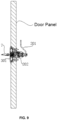
- the fixing panel is configured to fix the housing to a door panel.
- the embodiments of the present invention include the following advantageous effects.
- the rotary handle can be concealed by the cooperation of the rotary handle with the concealing part.
- the rotary handle can be unlocked by the concealing part by rotating the lock core, so that the rotary handle is partially ejected out of the housing so as to be held by the user.
- the rotary handle can be pressed to be concealed in the housing, thereby ameliorating the problems of the prior art door locks with unconcealable handles which protrude outside so as to be easily damaged or cause potential safety hazards.
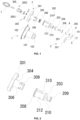
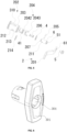
- Reference Numerals housing 1, fixing sleeve 101, first boss 1011, second boss 1012, fixing panel 102, mounting hole 103, latch component 2, latch 201, adjusting part 202, handle component 3, rotary handle 301, concealing part 302, mounting cavity 304, lock core 305, adjusting cylinder 203, adjusting sleeve 204, "L"-shaped groove 2041, positioning pin 205, adjusting spring 206, mounting support 207, handle cavity 208, spring cavity 209, limiting slot 210, adjustment limiting hole 211, first fixing limiting hole 306, second fixing limiting hole 212, elastic extendable block 307, push-out spring 308, positioning protrusion 309, positioning slot 310, first limiting block 311, second limiting block 312, return spring 313, insertion pin 3111, engaging base 3112, inclined restoring block 3113, shift block 3051, rotary lock head 3052, rotary lock disk 3053, shift lever 3054, shift lever groove 3055, first notch 2042, second notch 2043, groove
- connection may be fixed connection or detachable connection or integral connection, may be mechanical connection or electric connection, or may be direct coupling or indirect coupling via an intermediate medium or internal communication between two elements or mutual interaction between two elements, unless otherwise expressly defined.
- connection may be fixed connection or detachable connection or integral connection, may be mechanical connection or electric connection, or may be direct coupling or indirect coupling via an intermediate medium or internal communication between two elements or mutual interaction between two elements, unless otherwise expressly defined.
- an embodiment of the present invention provides a door or window lock with a concealable handle, which includes a housing 1, a latch component 2, and a handle component 3.
- the housing 1 includes a fixing sleeve 101 and a fixing panel 102.
- the fixing sleeve 101 and the fixing panel 102 are integrally molded.
- the fixing panel 102 is configured to fix the housing 1 to a door panel.
- the latch component 2 includes a latch 201 and an adjusting part 202.
- a mounting hole 103 is provided in the bottom of the fixing sleeve 101.
- the adjusting part 202 is arranged inside the fixing sleeve 101, and the adjusting part 202 has an adjusting end protruding from the fixing sleeve 101 through the mounting hole 103 and connected and fixed to the latch 201.
- the adjusting part 202 is configured to adjust the position of the latch 201.
- the handle component 3 includes a rotary handle 301 and a concealing part 302.
- a mounting cavity 304 is provided in the top surface of the rotary handle 301.
- the concealing part 302 is arranged at the bottom of the mounting cavity 304.
- the concealing part 302 is circumferentially fixed to the adjusting part 202 and mounted inside the fixing sleeve 101.
- the concealing part 302 is configured to control the relative position of the rotary handle 301 relative to the fixing sleeve 101.
- the rotary handle 301 is provided with a lock core 305.
- the lock core 305 is fixed inside the mounting cavity 304 and located above the concealing part 302.
- the bottom of the lock core 305 is engaged with the concealing part 302.
- the lock core 305 is adjusted by the concealing part 302 to a locked state.
- the rotary handle 301 is partially ejected out of the fixing sleeve 101 by the concealing part 302.
- the adjusting part 202 includes an adjusting cylinder 203.
- One end of the adjusting cylinder 203 is fixedly connected to the latch 201, and the latch 201 is located below the adjusting cylinder 203.
- the rotary handle 301 is partially slidably fitted to the inner cavity of the adjusting cylinder 203 in a direction in which the rotary handle 301 is pressed or ejected, and the rotary handle 301 is fixed relative to the adjusting cylinder 203 in a direction of rotation of the rotary handle 301.
- the adjusting part further includes an adjusting sleeve 204, a positioning pin 205, an adjusting spring 206, and a mounting support 207.
- the inner cavity of the adjusting cylinder 203 includes a spring cavity 209 and a handle cavity 208 configured to allow the handle component 3 to be mounted therein.
- the handle cavity 208 is configured such that the handle component 3 is mounted therein.
- the spring cavity 209 is arranged at the bottom of the handle cavity 208.
- An end of the spring cavity 209 away from the handle cavity 208 is in an open structure.
- a limiting slot 210 is provided in the side wall of the spring cavity 209.
- the adjusting sleeve 204 is sleeved outside the spring cavity 209.
- the adjusting spring 206 is arranged in the spring cavity 209.
- the adjusting sleeve 204 is fixedly assembled with the fixing sleeve 101 to form an "L"-shaped groove 2041 (See FIGS. 7 and 8 for details.
- a first boss 1011 and a second boss 1012 opposite to each other and both being in a tile shape are arranged on the inner side surface of the bottom of the fixing sleeve 101, and the "L"-shaped groove 2041 is formed by the first boss 1011 and the second boss 1012 together with the adjusting sleeve 204).
- the "L"-shaped groove 2041 is configured to limit a path of movement of the positioning pin 205.
- the other end of the mounting support 207 away from the adjusting spring 206 is fixedly connected to the latch 201.
- the mounting cavity 304 is provided as a hollow cylindrical structure with an upper opening.
- a first fixing limiting hole 306 is provided in a side wall close to the bottom of the mounting cavity 304.
- a second fixing limiting hole 212 is provided at a corresponding position of the handle cavity 208.
- the concealing part 302 is provided with an elastic extendable block 307.
- the elastic extendable block 307 is fixed at the inner bottom of the mounting cavity 304 and is slidably fitted in the first fixing limiting hole 306.
- the lock core 305 is engaged and fixed on the top of the elastic extendable block 307.
- the lock core 305 is configured to control an extended or retracted state of the elastic extendable block 307.
- a push-out spring 308 is arranged between the outer bottom of the mounting cavity 304 and the inner bottom of the handle cavity 208.
- a positioning protrusion 309 is arranged on an outer side wall of the mounting cavity 304.
- a positioning slot 310 extending in the direction in which the rotary handle 301 is pressed or ejected is provided at a corresponding position of the handle cavity 208.
- the positioning protrusion 309 fixes the rotary handle 301 in the positioning slot 310. Synchronous movements of the rotary handle 301 and the adjusting part 202 are limited by the positioning protrusion 309 and the positioning slot 310.
- the elastic extendable block 307 includes a first limiting block 311, a second limiting block 312, and a return spring 313.
- the first limiting block 311 is provided with an insertion pin 3111, an engaging base 3112, and an inclined restoring block 3113.
- the second limiting block 312 is in the same structure as the first limiting block 311.
- the first limiting block 311 and the second limiting block 312 are arranged opposite to each other.
- the return spring 313 has two ends simultaneously sleeved around the insertion pins 3111 of the first limiting block 312 and the second limiting block 312.
- the engaging base 3112 is engaged and fixed in the first fixing limiting hole 306 to lock the rotary handle 301 to the adjusting cylinder 203.
- the bottom of the lock core 305 is provided with a shift block 3051.
- the shift block 3051 is configured to shift the inclined restoring blocks 3113 so that the first limiting block 311 and the second limiting block 312 are moved towards each other in opposite directions to unlock the rotary handle 301 from the adjusting cylinder 203.
- the lock core 305 includes a rotary lock head 3052 and a rotary lock disk 3053.
- the rotary lock head 3052 is provided with a key insertion hole (not shown).
- a shift lever 3054 is arranged at the bottom of the rotary lock head 3052.
- a shift lever groove 3055 is provided in a surface of the rotary lock disk 3053 close to the shift lever 3054.
- the shift lever 3054 is plugged and fixed in the shift lever groove 3055.
- the shift block 3051 is fixed at the bottom of the rotary lock disk 3053.
- the rotary lock head 3052 and the rotary lock disk 3053 are moved synchronously under the action of the shift lever 3054 and the shift lever groove 3055.
- fixing screw holes are provided in the fixing panel 102. At least two fixing screw holes are provided.
- a first boss 1011 and a second boss 1012 are arranged on the inner side wall of the fixing sleeve 101 at positions corresponding to the adjusting sleeve 204.
- the adjusting sleeve 204 has a cylindrical structure opened at both ends.
- a first notches 2042 corresponding to the first boss 1011 and the second boss 1012 is provided in the side wall of the adjusting sleeve 204.
- a second notch 2043 is provided beside the first notch 2042.
- the second notch 2043 has a width greater than or equal to a diameter of the positioning pin 205, and the second notch 2043 has a height lower than that of the first notch 2042.
- the "L"-shaped groove 2041 described above is formed by the first notch 2042, the second notch 2043, together with one of the first boss 1011 and the second boss 1012. Two “L"-shaped grooves 2041 are provided.
- the limiting slot 210 is of a " ⁇ "-shape.
- the spring cavity 209 has a diameter smaller than that of the handle cavity 208.
- a groove 213 is provided around a portion of the spring cavity 209 connected to the handle cavity 208.
- a rubber ring 214 is arranged in the groove 213.
- this door or window lock with a concealable handle further includes a circlip 4.
- the spring cavity 209 is provided with a circlip groove 41 at its end close to the mounting support 207.
- the circlip 4 is mounted in the circlip groove 41. An end of the circlip 4 away from the latch 201 is brought into contact with the fixing sleeve 101.
- the latch 201 is fixed to the mounting support 207 by a fixing screw 5. An end of the circlip 4 away from the fixing screw 5 is in contact with the fixing sleeve 101. Further, the mounting support 207 is provided with a screw hole at its end away from the adjusting spring 206. The latch 201 is provided with a through hole. The fixing screw 5 passes through the through hole and is locked into the screw hole.
- the mounting support 207 is provided with a cuboid-shaped limiting region 6 at its end away from the adjusting spring 206.
- the latch 201 is provided with a corresponding rectangular hole 61.
- the rectangular hole 61 is sleeved on the cuboid-shaped limiting region 6.
- the mounting support 207 and the latch 201 can be fixed circumferentially to each other by fitting the cuboid-shaped limiting region 6 in the rectangular hole 61, so that the latch 201 is driven to rotate synchronously when the mounting support 207 rotates.
- a key 7 is inserted into the lock core 305.
- the key 7 will drive the lock core 305 to shift the elastic extendable block 307.
- the inclined restoring blocks 3113 of the first limiting block 311 and the second limiting block 312 are pushed by the shift block 3051, so that the first limiting block 311 and the second limiting block 312 are moved towards each other in opposite directions.
- the engaging bases 3112 of the first limiting block 311 and the second limiting block 312 are retracted inwardly and then unfixed from the second fixing limiting hole 212, respectively.
- the rotary handle 301 is pushed out of the surface of the fixing sleeve 101 under the action of the push-out spring 308.
- the latch 201 may be controlled by rotating the rotary handle 301 by the following control process.
- the latch 201 and the rotary handle 301 are both in a horizontal state.
- the latch 201 is also positioned at an angle of 90 degrees and limits the position of the door panel.
- the internal positioning pin 205 in this door or window lock is rotated by 90 degrees along a path defined by the bottom horizontal groove position of the "L"-shaped groove formed by the adjusting sleeve 204 and the housing 1.
- the rotary handle 301 is rotated to a position at an angle of 180 degrees from the initial state. During this process, the internal positioning pin 205 will be pushed by the projecting blocks inside the housing 1 into the limiting slot 210 and then be positioned by the limiting slot 210.
- the top of the rotary handle 301 is simply pressed, and then the handle component 3 is moved downward by the positioning effect of the positioning protrusion 309 and the positioning slot 310 until the engaging bases 3112 of the first limiting block 311 and the second limiting block 312 reach the position of the second fixing limiting hole 212, and the engaging bases 3112 are unblocked by the inner wall of the handle cavity 208 and then are protruded outward under the action of the return spring 313.
- the shift block 3051 is also pushed by the inclined restoring blocks 3113 of the first limiting block 311 and the second limiting block 312 to drive the lock core 305 to rotate to the initial position.
- the door or window lock allows the rotary handle 301 to be concealed by the cooperation of the rotary handle 301 with the concealing part 302.
- the rotary handle 301 can be unlocked by the concealing part 302 by rotating the lock core 305, so that the rotary handle 301 is partially ejected out of the housing 1 so as to be held by the user.
- the rotary handle 301 can be pressed to be concealed in the housing 1, thereby ameliorating the problems of the prior art door locks with unconcealable handles which protrude outside so as to be easily damaged or cause potential safety hazards.
- This door or window lock with a concealable handle is designed by making ingenious use of the characteristics of the respective structures, has a compact overall structure, can be adjusted effectively and conveniently, and therefore is suitable for widespread use in various places.
- an embodiment of the present invention provides a door or window lock with a concealable handle according to claim 1, which includes a housing 1, a latch component 2, and a handle component 3.
- the latch component 2 includes an adjusting cylinder 203.
- the adjusting cylinder 203 is provided with a positioning slot 310 extending in an axial direction.
- the adjusting cylinder 203 has an end portion protruding from the housing 1 and fixed to the latch 201.
- the handle component 3 includes a rotary handle 301 and an elastic extendable block 307.
- the rotary handle 301 is provided with a positioning protrusion 309.
- the positioning protrusion 309 is slidably fitted in the positioning slot 310 so that the rotary handle 301 can be moved axially relative to the adjusting cylinder 203 and cannot be rotated circumferentially.
- the elastic extendable block 307 is arranged in the rotary handle 301 and is configured to lock the relative position of the rotary handle 301 relative to the adjusting cylinder 203 in the axial direction so that the rotary handle 301 is kept in the housing 1, or is configured to unlock the relative position of the rotary handle 301 relative to the adjusting cylinder 203 in the axial direction so that the rotary handle 301 can be moved axially relative to the adjusting cylinder 203 so as to protrude from the housing 1.
- the door or window lock according to this embodiment is operated based on substantially the same principle and achieves substantially the same technical effects as those in the first embodiment, and therefore a detailed description is omitted here.
- the door or window lock allows the rotary handle to be concealed.
- the rotary handle can be unlocked by the concealing part by rotating the lock core, so that the rotary handle is partially ejected out of the housing so as to be held by the user.
- the rotary handle can be pressed to be concealed in the housing, thereby ameliorating the problems of the prior art door locks with unconcealable handles which protrude outside so as to be easily damaged or cause potential safety hazards.
Landscapes
- Engineering & Computer Science (AREA)
- Mechanical Engineering (AREA)
- Lock And Its Accessories (AREA)
Claims (9)
- Tür- oder Fensterschloss mit einem verdeckbaren Griff, umfassend: eine Griffkomponente (3), eine Riegelkomponente (2) und ein Gehäuse (1), wobei die Griffkomponente (3) einen Drehgriff (301) und ein Verdeckteil (302) umfasst, wobei der Drehgriff (301) mit einer Montagekammer (304) versehen ist, wobei das Verdeckteil (302) an einem Boden der Montagekammer (304) angeordnet ist, und das Verdeckteil (302) an der Riegelkomponente (2) befestigt und innerhalb des Gehäuses (1) montiert ist; und wobei das Verdeckteil (302) so konfiguriert ist, dass es eine Position des Drehgriffs (301) relativ zum Gehäuse (1) steuert,wobei der Drehgriff (301) mit einem Schließzylinder (305) versehen ist, wobei der Schließzylinder (305) innerhalb der Montagekammer (304) befestigt und über dem Verdeckteil (302) angeordnet ist, und ein Boden des Schließzylinders (305) mit dem Verdeckteil (302) in Eingriff steht, wobei, wenn der Drehgriff (301) so gedrückt wird, dass er im Gehäuse (1) verdeckt ist, der Schließzylinder (305) durch das Verdeckteil (302) in einen verriegelten Zustand versetzt wird; und wobei, wenn sich der Schließzylinder (305) in einem entriegelten Zustand befindet, der Drehgriff (301) durch das Verdeckteil (302) teilweise aus dem Gehäuse (1) ausgestoßen wird,wobei die Riegelkomponente (2) einen Riegel (201) und ein Einstellteil (202) umfasst, wobei in einem Boden des Gehäuses (1) ein Montageloch (103) vorgesehen ist, wobei das Einstellteil (202) innerhalb des Gehäuses (1) angeordnet ist, und das Einstellteil (202) durch das Montageloch (103) aus dem Gehäuse (1) herausragt und fest mit dem Riegel (201) verbunden ist; und wobei das Einstellteil (202) dazu konfiguriert ist, eine Position des Riegels (201) einzustellen,wobei das Einstellteil (202) einen Einstellzylinder (203) umfasst, wobei ein Ende des Einstellzylinders (203) fest mit dem Riegel (201) verbunden ist, wobei der Drehgriff (301) teilweise in eine innere Kammer des Einstellzylinders (203) derart eingepasst ist, dass der Drehgriff (301) in eine Richtung verschiebbar ist, in der der Drehgriff (301) gedrückt oder ausgestoßen wird, und wobei der Drehgriff (301) gegenüber dem Einstellzylinder (203) in einer Drehrichtung des Drehgriffs (301) befestigt ist,wobei das Tür- oder Fensterschloss mit einem verdeckbaren Griff ferner eine Einstellhülse (204), einen Positionierungsstift (205), eine Einstellfeder (206) und eine Montagehalterung (207) umfasst, wobei eine innere Kammer des Einstellzylinders (203) eine Federkammer (209) und eine Griffkammer (208) umfasst, die so konfiguriert ist, dass sie die Montage der Griffkomponente (3) darin ermöglicht, wobei die Griffkammer (208) so konfiguriert ist, dass sie die Montage der Griffkomponente (3) darin ermöglicht; wobei die Federkammer (209) an einem Boden der Griffkammer (208) angeordnet ist, wobei ein von der Griffkammer (208) entferntes Ende der Federkammer (209) eine offene Struktur annimmt, und wobei ein Begrenzungsschlitz (210) in einer Seitenwand der Federkammer (209) vorgesehen ist; wobei die Einstellhülse (204) außerhalb der Federkammer (209) aufgesetzt ist, wobei die Einstellfeder (206) in der Federkammer (209) angeordnet ist, wobei ein der Enden der Montagehalterung (207) in Kontakt mit der Einstellfeder (206) steht, wobei ein Einstellbegrenzungsloch (211) am Ende der Montagehalterung (207) vorgesehen ist, das mit der Einstellfeder (206) in Kontakt steht, und wobei der Positionierungsstift (205) sowohl durch den Begrenzungsschlitz (210) als auch durch das Einstellbegrenzungsloch (211) geführt ist;wobei die Einstellhülse (204) fest mit dem Gehäuse (1) zusammengebaut ist, um eine "L"-förmige Nut (2041) zu bilden, wobei die "L"-förmige Nut (2041) so konfiguriert ist, dass sie einen Bewegungsweg des Positionierungsstifts (205) begrenzt; und wobei ein von der Einstellfeder (206) entferntes Ende der Montagehalterung (207) fest mit dem Riegel (201) verbunden ist,wobei die Montagekammer (304) in einer hohlen zylindrischen Struktur mit einer oberen Öffnung vorgesehen ist, und wobei ein erstes befestigendes Begrenzungsloch (306) in einer Seitenwand vorgesehen ist, die nahe einem Boden der Montagekammer (304) liegt; wobei ein zweites befestigendes Begrenzungsloch (212) an einer entsprechenden Position der Griffkammer (208) vorgesehen ist; und wobei der Verdeckteil (302) mit einem elastischen ausfahrbaren Block (307) versehen ist, wobei der elastische ausfahrbare Block (307) an einem inneren Boden der Montagekammer (304) befestigt ist und verschiebbar in das erste befestigende Begrenzungsloch (306) eingepasst ist, und wobei der Schließzylinder (305) fest mit einem Oberteil des elastischen ausfahrbaren Blocks (307) in Eingriff steht; und wobei der Schließzylinder (305) so konfiguriert ist, dass er einen ausgefahrenen oder eingefahrenen Zustand des elastischen ausfahrbaren Blocks (307) steuert,wobei der elastische ausfahrbare Block (307) einen ersten Begrenzungsblock (311), einen zweiten Begrenzungsblock (312) und eine Rückstellfeder (313) umfasst, wobei der erste Begrenzungsblock (311) mit einem Einsteckstift (3111), einer Eingriffsbasis (3112) und einem geneigten Wiederherstellungsblock (3113) versehen ist, wobei der zweite Begrenzungsblock (312) dieselbe Struktur wie der erste Begrenzungsblock (311) aufweist, wobei der erste Begrenzungsblock (311) und der zweite Begrenzungsblock (312) einander gegenüberliegend angeordnet sind, wobei die Rückstellfeder (313) zwei Enden aufweist, die simultan auf Einsteckstifte (3111) des ersten Begrenzungsblocks (311) und des zweiten Begrenzungsblocks (312) aufgesetzt sind, und wobei die Eingriffsbasis (3112) fest in das erste befestigende Begrenzungsloch (306) eingreift, um den Drehgriff (301) am Einstellzylinder (203) zu verriegeln; und wobei ein Boden des Schließzylinders (305) mit einem Schiebeblock (3051) versehen ist, wobei der Schiebeblock (3051) dazu konfiguriert ist, geneigte Wiederherstellungsblöcke (3113) zu verschieben, so dass der erste Begrenzungsblock (311) und der zweite Begrenzungsblock (312) in entgegengesetzte Richtungen aufeinander zu bewegt werden, um so den Drehgriff (301) vom Einstellzylinder (203) zu entriegeln.
- Tür- oder Fensterschloss mit einem verdeckbaren Griff nach Anspruch 1, wobei eine Ausschubfeder (308) zwischen einem äußeren Boden der Montagekammer (304) und einem inneren Boden der Griffkammer (208) angeordnet ist; und wobei ein Positionierungsvorsprung (309) an einer äußeren Seitenwand der Montagekammer (304) angeordnet ist, wobei an einer entsprechenden Position der Griffkammer (208) ein Positionierungsschlitz (310) vorgesehen ist, der sich in einer Richtung erstreckt, in der der Drehgriff (301) gedrückt oder ausgestoßen wird, und wobei der Positionierungsvorsprung (309) den Drehgriff (301) im Positionierungsschlitz (310) fixiert.
- Tür- oder Fensterschloss mit einem verdeckbaren Griff nach Anspruch 1, wobei der Schließzylinder (305) einen drehbaren Schlosskopf (3052) und eine drehbare Schlossscheibe (3053) umfasst, wobei der drehbare Schlosskopf (3052) mit einem Schlüsseleinsteckloch versehen ist, wobei ein Schiebehebel (3054) an einem Boden des drehbaren Schlosskopfs (3052) angeordnet ist, wobei eine Schiebehebelnut (3055) in einer Oberfläche der drehbaren Schlossscheibe (3053), die nahe dem Schiebehebel (3054) liegt, vorgesehen ist, und wobei der Schiebehebel (3054) fest in die Schiebehebelnut (3055) eingesteckt ist; wobei der Schiebeblock (3051) an dem Boden der drehbaren Schlossscheibe (3053) befestigt ist; und wobei der drehbare Schlosskopf (3052) und die drehbare Schlossscheibe (3053) unter einer Einwirkung des Schiebehebels (3054) und der Schiebehebelnut (3055) synchron bewegt werden.
- Tür- oder Fensterschloss mit einem verdeckbaren Griff nach Anspruch 1, wobei zwei hervorstehende Blöcke an einer inneren Seitenwand des Gehäuses (1) an Positionen, die der Einstellhülse (204) entsprechen, angeordnet sind; wobei die Einstellhülse (204) eine zylindrische Struktur annimmt, die an beiden Enden geöffnet ist, wobei erste Kerben (2042), die den beiden hervorstehenden Blöcken entsprechen, in einer Seitenwand der Einstellhülse (204) vorgesehen sind, wobei zweite Kerben (2043) neben den ersten Kerben (2042) vorgesehen sind, wobei jede der zweiten Kerben (2043) eine Breite aufweist, die größer oder gleich dem Durchmesser des Positionierungsstifts (205) ist, und wobei jede der zweiten Kerben (2043) eine Höhe aufweist, die geringer als die der entsprechenden ersten Kerbe (2042) ist; und wobei die "L"-förmige Nut (2041) durch die erste Kerbe (2042), die zweite Kerbe (2043) und einen der beiden hervorstehenden Blöcke gebildet wird, und wobei zwei "L"-förmige Nuten (2041) vorgesehen sind.
- Tür- oder Fensterschloss mit einem verdeckbaren Griff nach Anspruch 1, wobei der Begrenzungsschlitz (210) eine "Γ"-Form aufweist.
- Tür- oder Fensterschloss mit einem verdeckbaren Griff nach einem der Ansprüche 1 bis 5, wobei an einem von der Einstellfeder (206) entfernten Ende der Montagehalterung (207) ein quaderförmiger Begrenzungsbereich (6) vorgesehen ist, und der Riegel (201) mit einem entsprechenden rechteckigen Loch (61) versehen ist, wobei das rechteckige Loch (61) auf dem quaderförmigen Begrenzungsbereich (6) aufgesetzt ist.
- Tür- oder Fensterschloss mit einem verdeckbaren Griff nach einem der Ansprüche 1 bis 5, wobei die Federkammer (209) einen kleineren Durchmesser als die Griffkammer (208) aufweist, wobei eine Nut (213) außerhalb eines mit der Griffkammer (208) verbundenen Abschnitts der Federkammer (209) vorgesehen ist, und wobei ein Gummiring (214) in der Nut (213) angeordnet ist.
- Tür- oder Fensterschloss mit einem verdeckbaren Griff nach einem der Ansprüche 1 bis 5, der ferner einen Sicherungsring (4) umfasst, wobei an einem der Montagehalterung (207) nahe liegenden Ende der Federkammer (209) eine Sicherungsringnut (41) vorgesehen ist, wobei der Sicherungsring (4) in der Sicherungsringnut (41) montiert ist, und wobei ein von dem Riegel (201) entferntes Ende des Sicherungsrings (4) mit der Befestigungshülse (101) in Kontakt steht,wobei vorzugsweise der Riegel (201) durch eine Befestigungsschraube (5) an der Montagehalterung (207) befestigt ist, und ein von der Befestigungsschraube (5) entferntes Ende des Sicherungsrings (4) mit der Befestigungshülse (101) in Kontakt steht,wobei vorzugsweise an einem von der Einstellfeder (206) entfernten Ende der Montagehalterung (207) ein Schraubenloch vorgesehen ist, der Riegel (201) mit einem Durchgangsloch versehen ist und die Befestigungsschraube (5) durch das Durchgangsloch verläuft und im Schraubenloch verriegelt wird.
- Tür- oder Fensterschloss mit einem verdeckbaren Griff nach Anspruch 1, wobei das Gehäuse (1) eine Befestigungshülse (101) und eine Befestigungsplatte (102) umfasst, wobei die Befestigungshülse (101) und die Befestigungsplatte (102) integral geformt sind, und wobei die Befestigungsplatte (102) dazu konfiguriert ist, das Gehäuse (1) an einer Türplatte zu befestigen.
Applications Claiming Priority (2)
| Application Number | Priority Date | Filing Date | Title |
|---|---|---|---|
| CN202010072147.7A CN111173367B (zh) | 2020-01-21 | 2020-01-21 | 一种把手可隐藏的门窗锁 |
| PCT/CN2020/134635 WO2021147541A1 (zh) | 2020-01-21 | 2020-12-08 | 一种把手可隐藏的门窗锁 |
Publications (4)
| Publication Number | Publication Date |
|---|---|
| EP3875715A1 EP3875715A1 (de) | 2021-09-08 |
| EP3875715A4 EP3875715A4 (de) | 2022-04-06 |
| EP3875715B1 true EP3875715B1 (de) | 2025-04-23 |
| EP3875715C0 EP3875715C0 (de) | 2025-04-23 |
Family
ID=70654941
Family Applications (1)
| Application Number | Title | Priority Date | Filing Date |
|---|---|---|---|
| EP20853593.0A Active EP3875715B1 (de) | 2020-01-21 | 2020-12-08 | Tür- oder fensterschloss mit verdeckbarem griff |
Country Status (3)
| Country | Link |
|---|---|
| EP (1) | EP3875715B1 (de) |
| CN (1) | CN111173367B (de) |
| WO (1) | WO2021147541A1 (de) |
Families Citing this family (6)
| Publication number | Priority date | Publication date | Assignee | Title |
|---|---|---|---|---|
| CN111173367B (zh) * | 2020-01-21 | 2024-07-19 | 江苏三乔智能科技有限公司 | 一种把手可隐藏的门窗锁 |
| CN111719951B (zh) * | 2020-05-29 | 2024-01-05 | 宁波生久科技有限公司 | 一体式弹子锁芯把手面板锁 |
| CN112412175A (zh) * | 2020-12-15 | 2021-02-26 | 宁波星宏智能技术有限公司 | 一种远程智能家居无线监控系统 |
| CN113914708A (zh) * | 2021-09-17 | 2022-01-11 | 李家超 | 一种门窗把手 |
| CN115178821B (zh) * | 2022-08-20 | 2024-02-13 | 南通合强液压科技有限公司 | 一种转子焊接专用液压机 |
| CN117127861B (zh) * | 2023-07-28 | 2025-10-28 | 北京无线电测量研究所 | 一种隐藏式按压快锁及电子设备 |
Family Cites Families (16)
| Publication number | Priority date | Publication date | Assignee | Title |
|---|---|---|---|---|
| CA702325A (en) * | 1965-01-19 | H. Dettmer Martin | Draw lock for a sealed cabinet door | |
| ES2008987A6 (es) * | 1988-05-05 | 1989-08-16 | Ojmar Sa | Mejoras en el objeto de la patente principal numero 8700654 "un sistema de piton excentrico para cerraduras". |
| JP2649099B2 (ja) * | 1990-09-05 | 1997-09-03 | 美和ロック株式会社 | 扉の錠装置 |
| CN2075681U (zh) * | 1990-10-09 | 1991-04-24 | 李诗通 | 隐藏式把手 |
| JP2738649B2 (ja) * | 1994-03-18 | 1998-04-08 | 株式会社サンポウロック | ハンドルロック |
| US6474119B1 (en) * | 1999-01-28 | 2002-11-05 | Fastec Industrial Corp. | Pop-up handle assembly |
| JP4266759B2 (ja) * | 2003-09-19 | 2009-05-20 | 株式会社アルファ | ハンドル錠 |
| DE202007013514U1 (de) * | 2007-09-27 | 2007-12-06 | Emka Beschlagteile Gmbh & Co. Kg | Drehspannverschluss mit Betätigungsgriffsicherung |
| CN201339348Y (zh) * | 2009-01-07 | 2009-11-04 | 亚萨合莱-王力保安制品有限公司 | 手柄整体可藏式全自动门锁 |
| JP6015078B2 (ja) * | 2012-04-05 | 2016-10-26 | 富士電機株式会社 | 自動販売機のハンドルロック装置 |
| JP5982441B2 (ja) * | 2014-09-08 | 2016-08-31 | タキゲン製造株式会社 | 扉のポップアウト型ロックハンドル装置 |
| JP5982440B2 (ja) * | 2014-09-08 | 2016-08-31 | タキゲン製造株式会社 | 扉のポップアウト型ロックハンドル装置 |
| IT201600076562A1 (it) * | 2016-09-02 | 2018-03-02 | Cev Lab S R L Con Unico Socio | Dispositivo di chiusura |
| CN209556661U (zh) * | 2018-09-17 | 2019-10-29 | 江苏三乔智能科技有限公司 | 一种门窗锁紧机构 |
| CN211874143U (zh) * | 2020-01-21 | 2020-11-06 | 江苏三乔智能科技有限公司 | 一种把手可隐藏的门窗锁 |
| CN111173367B (zh) * | 2020-01-21 | 2024-07-19 | 江苏三乔智能科技有限公司 | 一种把手可隐藏的门窗锁 |
-
2020
- 2020-01-21 CN CN202010072147.7A patent/CN111173367B/zh active Active
- 2020-12-08 WO PCT/CN2020/134635 patent/WO2021147541A1/zh not_active Ceased
- 2020-12-08 EP EP20853593.0A patent/EP3875715B1/de active Active
Also Published As
| Publication number | Publication date |
|---|---|
| EP3875715A1 (de) | 2021-09-08 |
| EP3875715A4 (de) | 2022-04-06 |
| CN111173367A (zh) | 2020-05-19 |
| WO2021147541A1 (zh) | 2021-07-29 |
| EP3875715C0 (de) | 2025-04-23 |
| CN111173367B (zh) | 2024-07-19 |
Similar Documents
| Publication | Publication Date | Title |
|---|---|---|
| EP3875715B1 (de) | Tür- oder fensterschloss mit verdeckbarem griff | |
| US7159908B2 (en) | Window sash latch | |
| EP1153184B1 (de) | Griffkontrolle für ein einsteckschloss | |
| CN212529919U (zh) | 锁紧机构及具有其的车辆 | |
| CA2293169C (en) | Lever handle controller | |
| WO2024131955A1 (zh) | 旋转锁止机构、旋转关节组件及医疗设备 | |
| CN111188537B (zh) | 锁芯、锁具及钥匙 | |
| JP3236776U (ja) | デュアルパスワードキーシリンダー及びデュアルパスワードダイヤル錠 | |
| KR200456973Y1 (ko) | 클러치 구조를 갖는 문 잠금장치 | |
| CN114458090B (zh) | 执手连动结构和执手组件 | |
| JPH0624531Y2 (ja) | 平面ハンドルにおけるラツチロツク装置 | |
| CN223621397U (zh) | 一种天地插双向传动盒 | |
| KR200204006Y1 (ko) | 가구용 자물쇠 | |
| CN211286989U (zh) | 把手组件及锁具 | |
| KR200239178Y1 (ko) | 가구용 자물쇠 | |
| CN221171423U (zh) | 连接组件、锁定机构及led显示装置 | |
| CN112755512A (zh) | 一种手柄的转动结构 | |
| CN209942431U (zh) | 闩锁及闩锁组件 | |
| JP2001295515A (ja) | サムターン | |
| EP3995319B1 (de) | Lenkrollensystem | |
| CN210422217U (zh) | 转钮锁 | |
| CN218999724U (zh) | 推拉式伞巢结构 | |
| US20250243694A1 (en) | Replacement lock for storefront door | |
| US20180179794A1 (en) | Security latch for sashes | |
| KR200247673Y1 (ko) | 도어잠금장치 |
Legal Events
| Date | Code | Title | Description |
|---|---|---|---|
| STAA | Information on the status of an ep patent application or granted ep patent |
Free format text: STATUS: UNKNOWN |
|
| STAA | Information on the status of an ep patent application or granted ep patent |
Free format text: STATUS: THE INTERNATIONAL PUBLICATION HAS BEEN MADE |
|
| PUAI | Public reference made under article 153(3) epc to a published international application that has entered the european phase |
Free format text: ORIGINAL CODE: 0009012 |
|
| STAA | Information on the status of an ep patent application or granted ep patent |
Free format text: STATUS: REQUEST FOR EXAMINATION WAS MADE |
|
| 17P | Request for examination filed |
Effective date: 20210225 |
|
| AK | Designated contracting states |
Kind code of ref document: A1 Designated state(s): AL AT BE BG CH CY CZ DE DK EE ES FI FR GB GR HR HU IE IS IT LI LT LU LV MC MK MT NL NO PL PT RO RS SE SI SK SM TR |
|
| RAP3 | Party data changed (applicant data changed or rights of an application transferred) |
Owner name: JIANGSU SANJO INTELLIGENT TECHNOLOGY CO., LTD |
|
| RIN1 | Information on inventor provided before grant (corrected) |
Inventor name: XIAO, HEPING |
|
| RIC1 | Information provided on ipc code assigned before grant |
Ipc: E05B 13/10 20060101ALI20211123BHEP Ipc: E05B 15/10 20060101ALI20211123BHEP Ipc: E05B 15/00 20060101ALI20211123BHEP Ipc: E05B 3/00 20060101ALI20211123BHEP Ipc: E05B 5/00 20060101AFI20211123BHEP |
|
| STAA | Information on the status of an ep patent application or granted ep patent |
Free format text: STATUS: EXAMINATION IS IN PROGRESS |
|
| A4 | Supplementary search report drawn up and despatched |
Effective date: 20220303 |
|
| RIC1 | Information provided on ipc code assigned before grant |
Ipc: E05B 13/10 20060101ALI20220225BHEP Ipc: E05B 15/10 20060101ALI20220225BHEP Ipc: E05B 15/00 20060101ALI20220225BHEP Ipc: E05B 3/00 20060101ALI20220225BHEP Ipc: E05B 5/00 20060101AFI20220225BHEP |
|
| 17Q | First examination report despatched |
Effective date: 20220314 |
|
| DAV | Request for validation of the european patent (deleted) | ||
| DAX | Request for extension of the european patent (deleted) | ||
| REG | Reference to a national code |
Ref country code: DE Free format text: PREVIOUS MAIN CLASS: E05B0005000000 Ref country code: DE Ref legal event code: R079 Ref document number: 602020050121 Country of ref document: DE Free format text: PREVIOUS MAIN CLASS: E05B0005000000 Ipc: E05C0003040000 |
|
| GRAP | Despatch of communication of intention to grant a patent |
Free format text: ORIGINAL CODE: EPIDOSNIGR1 |
|
| STAA | Information on the status of an ep patent application or granted ep patent |
Free format text: STATUS: GRANT OF PATENT IS INTENDED |
|
| RIC1 | Information provided on ipc code assigned before grant |
Ipc: E05C 3/04 20060101AFI20241025BHEP |
|
| INTG | Intention to grant announced |
Effective date: 20241113 |
|
| GRAS | Grant fee paid |
Free format text: ORIGINAL CODE: EPIDOSNIGR3 |
|
| GRAA | (expected) grant |
Free format text: ORIGINAL CODE: 0009210 |
|
| STAA | Information on the status of an ep patent application or granted ep patent |
Free format text: STATUS: THE PATENT HAS BEEN GRANTED |
|
| AK | Designated contracting states |
Kind code of ref document: B1 Designated state(s): AL AT BE BG CH CY CZ DE DK EE ES FI FR GB GR HR HU IE IS IT LI LT LU LV MC MK MT NL NO PL PT RO RS SE SI SK SM TR |
|
| REG | Reference to a national code |
Ref country code: GB Ref legal event code: FG4D |
|
| REG | Reference to a national code |
Ref country code: CH Ref legal event code: EP |
|
| REG | Reference to a national code |
Ref country code: DE Ref legal event code: R096 Ref document number: 602020050121 Country of ref document: DE |
|
| REG | Reference to a national code |
Ref country code: IE Ref legal event code: FG4D |
|
| U01 | Request for unitary effect filed |
Effective date: 20250522 |
|
| U07 | Unitary effect registered |
Designated state(s): AT BE BG DE DK EE FI FR IT LT LU LV MT NL PT RO SE SI Effective date: 20250530 |
|
| PG25 | Lapsed in a contracting state [announced via postgrant information from national office to epo] |
Ref country code: ES Free format text: LAPSE BECAUSE OF FAILURE TO SUBMIT A TRANSLATION OF THE DESCRIPTION OR TO PAY THE FEE WITHIN THE PRESCRIBED TIME-LIMIT Effective date: 20250423 |
|
| PG25 | Lapsed in a contracting state [announced via postgrant information from national office to epo] |
Ref country code: NO Free format text: LAPSE BECAUSE OF FAILURE TO SUBMIT A TRANSLATION OF THE DESCRIPTION OR TO PAY THE FEE WITHIN THE PRESCRIBED TIME-LIMIT Effective date: 20250723 Ref country code: GR Free format text: LAPSE BECAUSE OF FAILURE TO SUBMIT A TRANSLATION OF THE DESCRIPTION OR TO PAY THE FEE WITHIN THE PRESCRIBED TIME-LIMIT Effective date: 20250724 |
|
| PG25 | Lapsed in a contracting state [announced via postgrant information from national office to epo] |
Ref country code: PL Free format text: LAPSE BECAUSE OF FAILURE TO SUBMIT A TRANSLATION OF THE DESCRIPTION OR TO PAY THE FEE WITHIN THE PRESCRIBED TIME-LIMIT Effective date: 20250423 |
|
| PG25 | Lapsed in a contracting state [announced via postgrant information from national office to epo] |
Ref country code: HR Free format text: LAPSE BECAUSE OF FAILURE TO SUBMIT A TRANSLATION OF THE DESCRIPTION OR TO PAY THE FEE WITHIN THE PRESCRIBED TIME-LIMIT Effective date: 20250423 |
|
| PG25 | Lapsed in a contracting state [announced via postgrant information from national office to epo] |
Ref country code: RS Free format text: LAPSE BECAUSE OF FAILURE TO SUBMIT A TRANSLATION OF THE DESCRIPTION OR TO PAY THE FEE WITHIN THE PRESCRIBED TIME-LIMIT Effective date: 20250723 |
|
| PG25 | Lapsed in a contracting state [announced via postgrant information from national office to epo] |
Ref country code: IS Free format text: LAPSE BECAUSE OF FAILURE TO SUBMIT A TRANSLATION OF THE DESCRIPTION OR TO PAY THE FEE WITHIN THE PRESCRIBED TIME-LIMIT Effective date: 20250823 |