EP3875291A1 - Reifendrucksensor - Google Patents
Reifendrucksensor Download PDFInfo
- Publication number
- EP3875291A1 EP3875291A1 EP19880922.0A EP19880922A EP3875291A1 EP 3875291 A1 EP3875291 A1 EP 3875291A1 EP 19880922 A EP19880922 A EP 19880922A EP 3875291 A1 EP3875291 A1 EP 3875291A1
- Authority
- EP
- European Patent Office
- Prior art keywords
- valve
- tire pressure
- pressure sensor
- valve rod
- hole
- Prior art date
- Legal status (The legal status is an assumption and is not a legal conclusion. Google has not performed a legal analysis and makes no representation as to the accuracy of the status listed.)
- Granted
Links
Images


Classifications
-
- B—PERFORMING OPERATIONS; TRANSPORTING
- B60—VEHICLES IN GENERAL
- B60C—VEHICLE TYRES; TYRE INFLATION; TYRE CHANGING; CONNECTING VALVES TO INFLATABLE ELASTIC BODIES IN GENERAL; DEVICES OR ARRANGEMENTS RELATED TO TYRES
- B60C23/00—Devices for measuring, signalling, controlling, or distributing tyre pressure or temperature, specially adapted for mounting on vehicles; Arrangement of tyre inflating devices on vehicles, e.g. of pumps or of tanks; Tyre cooling arrangements
- B60C23/02—Signalling devices actuated by tyre pressure
- B60C23/04—Signalling devices actuated by tyre pressure mounted on the wheel or tyre
- B60C23/0491—Constructional details of means for attaching the control device
- B60C23/0494—Valve stem attachments positioned inside the tyre chamber
-
- B—PERFORMING OPERATIONS; TRANSPORTING
- B60—VEHICLES IN GENERAL
- B60C—VEHICLE TYRES; TYRE INFLATION; TYRE CHANGING; CONNECTING VALVES TO INFLATABLE ELASTIC BODIES IN GENERAL; DEVICES OR ARRANGEMENTS RELATED TO TYRES
- B60C23/00—Devices for measuring, signalling, controlling, or distributing tyre pressure or temperature, specially adapted for mounting on vehicles; Arrangement of tyre inflating devices on vehicles, e.g. of pumps or of tanks; Tyre cooling arrangements
- B60C23/02—Signalling devices actuated by tyre pressure
- B60C23/04—Signalling devices actuated by tyre pressure mounted on the wheel or tyre
- B60C23/0408—Signalling devices actuated by tyre pressure mounted on the wheel or tyre transmitting the signals by non-mechanical means from the wheel or tyre to a vehicle body mounted receiver
-
- B—PERFORMING OPERATIONS; TRANSPORTING
- B60—VEHICLES IN GENERAL
- B60C—VEHICLE TYRES; TYRE INFLATION; TYRE CHANGING; CONNECTING VALVES TO INFLATABLE ELASTIC BODIES IN GENERAL; DEVICES OR ARRANGEMENTS RELATED TO TYRES
- B60C29/00—Arrangements of tyre-inflating valves to tyres or rims; Accessories for tyre-inflating valves, not otherwise provided for
- B60C29/005—Arrangements of tyre-inflating valves to tyres or rims; Accessories for tyre-inflating valves, not otherwise provided for characterised by particular features of the valve stem
-
- B—PERFORMING OPERATIONS; TRANSPORTING
- B60—VEHICLES IN GENERAL
- B60C—VEHICLE TYRES; TYRE INFLATION; TYRE CHANGING; CONNECTING VALVES TO INFLATABLE ELASTIC BODIES IN GENERAL; DEVICES OR ARRANGEMENTS RELATED TO TYRES
- B60C29/00—Arrangements of tyre-inflating valves to tyres or rims; Accessories for tyre-inflating valves, not otherwise provided for
- B60C29/02—Connection to rims
Definitions
- the present application relates to the field of tire pressure detection technologies, and in particular, to a tire pressure sensor.
- a pressure-sensor based tire pressure monitoring system is also referred to as a PSB TPMS.
- the PSB TPMS uses a tire pressure sensor installed on a tire to measure barometric pressure and temperature of the tire, uses a wireless transmitter to send pressure information from a tire interior to a tire pressure detection terminal, and displays barometric pressure data of the tire.
- the system will alert the vehicle owner.
- the owner may set a tire pressure alarm value range and a temperature alarm value according to a vehicle type, car using habits and geographical location.
- a traditional tire pressure sensor includes a sensor and a valve mounted to the sensor.
- the sensor is configured to detect tire information inside the tire
- the valve is configured to inflate and deflate the tire.
- the inventor finds that the current tire pressure sensor can only be provided with a single type of valve, and cannot be compatible with the metal valve and the rubber valve, limiting the application range of the tire pressure sensor. Therefore, the prior art needs to be improved.
- embodiments of the present invention provide a tire pressure sensor capable of replacing a valve assembly according to different use requirements.
- a tire pressure sensor including: a sensor assembly provided with a through hole; a valve assembly including a valve rod, a valve cover mounted to one end of the valve rod, a rod sleeve sleeved between two ends of the valve rod and a fastener connected to the other end of the valve rod through threads, one of the fastener and the valve rod passing through the through hole, and the fastener and the valve rod clamping the sensor assembly, where there are at least two sets of valve assemblies, the at least two sets of the valve assemblies being alternatively connected to the sensor assembly, a rod sleeve of one of the at least two sets of the valve assemblies being made of a metal material, and a rod sleeve of the other of the at least two sets of the valve assemblies being made of a rubber material.
- the sensor assembly includes a base and a mounting stand connected to the base, the base being configured to fit a rim, and the mounting stand being provided with the through hole.
- the mounting stand is provided with a groove, the through hole being in communication with the groove, and the valve assembly being inserted into the groove.
- the mounting stand includes a first surface and a second surface opposite to each other; the groove being disposed on the first surface, and the groove including a groove bottom, the groove bottom being provided with the through hole penetrating through the second surface; the valve assembly further includes a fastener, and the valve rod is further provided with a connecting portion; the valve rod abutting against the groove bottom, the connecting portion passing through the through hole away from one end of the valve rod and being connected to the fastener through threads, and the fastener abutting against the second surface.
- the mounting stand includes a first surface and a second surface opposite to each other; the groove being disposed on the first surface, and the groove including a groove bottom, the groove bottom being provided with the through hole penetrating through the second surface; the valve assembly further includes a fastener, the fastener including a limiting portion and a connecting portion connected to the limiting portion; the limiting portion abutting against the second surface, one end of the connecting portion far from the limiting portion passing through the through hole and being connected to the valve rod through threads, and the valve rod abutting against the groove bottom.
- valve rod is provided with a screw hole aligned with the through hole, the connecting portion being connected to the screw hole through threads.
- the second surface is provided with a strengthened piece, the strengthened piece abutting between the limiting portion and the second surface.
- the mounting stand further includes a third surface connected between the first surface and the second surface, the third surface being provided with a slot; a connecting piece that is attached to the third surface extending from the strengthened piece, and a holding piece that is inserted into the slot extending from the connecting piece.
- the holding piece is provided with a barb, the barb abutting against a side wall of the slot.
- the groove bottom is spherical, and the valve rod may rotate along the groove bottom.
- the valve rod includes a mounting portion, one end of the mounting portion being hemispherical and abutting against the groove bottom.
- the groove further includes a first limiting surface connected to the groove bottom; and a second limiting surface is provided between two ends of the mounting portion; the groove being provided with the second limiting surface, and the first limiting surface abutting against the second limiting surface, so that the valve rod may rotate relative to the sensor assembly about a preset axis, the preset axis being normal to the first limiting surface or the second limiting surface.
- the through hole is a waist-shaped hole, the waist-shaped hole being normal to the preset axis in a length direction.
- the second surface has a same radian as the groove bottom.
- the base includes a case bottom and an upper case, the upper case and the case bottom being connected by laser welding, and the case bottom and the upper case forming a cavity, the cavity being configured to mount a circuit board, a battery and an antenna, the circuit board, the battery and the antenna forming a transmitting board.
- valve rod includes a central axis, the central axis passing through the center of gravity of the sensor assembly.
- the sensor assembly includes two opposite sides, one side being provided with a battery, the central axis being located between the two sides of the sensor assembly, and the central axis being closer to the side that is of the sensor assembly and that is provided with the battery.
- the rod sleeve made of metal includes a valve seal ring, a nut gasket and a nut, the valve seal ring, the nut gasket and the nut being sequentially sleeved on the valve rod, and among the valve seal ring, the nut gasket and the nut, the nut being closer to the valve cover.
- the tire pressure sensor in the embodiments of the present invention includes: a sensor assembly provided with a through hole; a valve assembly including a valve rod, a valve cover mounted to one end of the valve rod, a rod sleeve sleeved between two ends of the valve rod, and a fastener connected to the other end of the valve rod through threads, one of the fastener and the valve rod passing through the through hole, and the fastener and the valve rod clamping the sensor assembly, where there are at least two sets of valve assemblies, the at least two sets of the valve assemblies being alternatively connected to the sensor assembly, a rod sleeve of one of the at least two sets of the valve assemblies being made of a metal material, and a rod sleeve of the other of the at least two sets of the valve assemblies being made of a rubber material.
- the at least two sets of valve assemblies with different specifications are disposed, which may alternately be connected to the sensor assembly, and a user may mount, according to requirements, a valve assembly
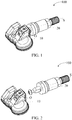
- an embodiment of the present invention provides a tire pressure sensor 100.
- the tire pressure sensor 100 includes a sensor assembly 10 and at least two sets of valve assemblies 20 with different specifications.
- the at least two sets of valve assemblies 20 with different specifications may alternately be connected to the sensor assembly 10.
- the sensor assembly 10 includes a base 11 and a mounting stand 12 connected to the base 12.
- the base 11 may be made of a plastic material, and the base 11 is provided with a cavity. Components such as a circuit board 13, a battery 14, and an antenna 15 are mounted in the cavity.
- the circuit board 13 carries a chip set, for example, a wireless transmission chip and a pressure detection chip.
- the pressure detection chip is provided with an air pressure detection hole and is configured to detect air pressure in the air pressure detection hole.
- the wireless transmission chip is connected to the antenna 15 and is configured to be wirelessly connected to a tire pressure monitoring terminal located on an automobile dashboard.
- the battery 14 is a button battery, the battery 14 and the antenna 15 are connected to the circuit board 13 by soldering, and the battery 14, the antenna 15 and the circuit board 13 form a transmitting board.
- the base 11 includes a case bottom 110 and an upper case 111 connected to the case bottom 110, the upper case 111 being connected to the case bottom 110 to form the cavity.
- the case bottom 110 may be made of a light-transmissive material, and a surface that is of the case bottom 110 and that faces away from the upper case 111 is configured to fit a rim of a tire.
- the upper case 111 may be made of a dark opaque material.
- a surface that is of the upper case 111 and that faces away from the case bottom 110 is provided with an air hole 1110, the air hole 1110 being aligned with the air pressure detection hole.
- the air hole 1110 and the air pressure detection hole are sealed using a seal ring 16.
- the upper case 111 and the case bottom 110 are connected through laser welding.
- the upper case 111 and the case bottom 110 are connected through potting.
- the cavity formed by the upper case 111 and the case bottom 110 through laser welding may have good gas tightness.
- the upper case 111 and the case bottom 110 have high assembly efficiency, and the damage of the colloid to the human body and the pollution to the environment are reduced.
- the mounting stand 12 is disposed on a surface that is of the upper case 111 and that is far away from the case bottom 110.
- the mounting stand 12 includes a first surface 120, a second surface 121 and a third surface 122.
- the first surface 120 and the second surface 121 are both vertically disposed relative to the case bottom 110, and the third surface 122 is connected between the first surface 120 and the second surface 121.
- the third surface 122 is disposed away from the case bottom 110.
- the first surface 120 is provided with a groove 123, the groove 123 including a groove bottom 124 and a first limiting surface 125 connected to the groove bottom 124.
- the groove bottom 124 is a curved surface.
- the groove bottom 124 is a spherical surface.
- the groove bottom 124 is provided with a through hole 126 penetrating through the groove bottom 124 and the second surface 121, that is, the through hole 126 is in communication with the groove 123.
- the through hole 126 is a waist-shaped hole, the waist-shaped hole 126 being vertically disposed relative to the shell bottom 110 in a length direction.
- the two first limiting surfaces 125 are disposed opposite to each other, and the two first limiting surfaces 125 are vertically disposed relative to the case bottom 110.
- the first limiting surface 125 is a plane, and two curved surfaces disposed opposite to each other are connected between the two first limiting surfaces 125.
- the second surface 121 is provided with a strengthened piece 1210.
- the strengthened piece 1210 may be made of a material such as stainless steel or manganese steel with higher strength, and the through hole 126 penetrates through the strengthened piece 1210.
- a connecting piece 1211 extends from the strengthened piece 1210, the connecting piece 1211 being attached to the third surface 122, and a holding piece 1212 extending from the connecting piece 1211 toward a direction of the third surface 122.
- the holding piece 1212 is provided with a barb 1213.
- the third surface 122 is provided with a slot 1220 for inserting the holding piece 1212.
- the holding piece 1212 is inserted into the slot 1220, and the barb 1213 abuts against a side wall of the slot 1220.
- a maximum distance between the case bottom 110 and the mounting stand 12 does not exceed a preset distance, so that the sensor assembly 10 can fit the rim of the tire better, to prevent the tire pressure sensor 100 from suspending during assembling and disassembling of the tire, so that the sensor assembly 20 is not easily damaged.
- each set of the valve assemblies 20 is detachably connected to the sensor assembly 10.
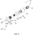
- Each set of the valve assemblies (20) includes a fastener 21, a valve rod 22, a valve cover 23 and a rod sleeve 24.
- the fastener 21 is detachably connected to one end of the valve rod 22, the valve cover 23 is mounted to the other end that is of the valve rod 22 and that faces away from the fastener 21, and the rod sleeve 24 is sleeved between the two ends of the valve rod 22.
- the fastener 21 passes through the through hole 126, and the fastener 21 is connected to the valve rod 22 through threads.
- the fastener 21 and the valve rod 22 clamp the sensor assembly 10.
- the fastener 21 includes a limiting portion 210 and a connecting portion 211 connected to the limiting portion 210.
- One end that is of the connecting portion 211 and that faces away from the limiting portion 210 passes through the through hole 126 and is connected to the valve rod 22 through threads.
- the limiting portion 210 abuts against a surface that is of the strengthened piece 1210 and that faces away from the second surface 121, and the valve rod 22 abuts against the groove bottom 124.
- the valve rod 22 is provided with a connecting portion 211, and the connecting portion is provided at one end facing away from the valve cover 23.
- the valve rod 22 abuts against the groove bottom 124, and one end that is of the connecting portion 211 and that faces away from the valve rod 22 passes through the through hole 126 and is connected to the fastener 21 through threads, and the fastener 21 abuts against a surface that is of the strengthened piece 1210 and that faces away from the second surface 121. Therefore, one end of the fastener 21 and the valve rod 22 passes through the through hole 126.
- the valve rod 22 may be made of metal such as copper.
- the valve rod 22 includes a mounting portion 220, a rod portion 221 connected to the mounting portion 220 and a mouth portion 222 connected to the rod portion 221.
- the valve rod 22 is provided with a gas path, the gas path passing through the mounting portion 220, the rod portion 221 and the mouth portion 222, and a valve core being provided in the gas path.
- the mouth portion 222 is detachably connected to the valve cover 23.
- the mouth portion 222 is connected to the valve cover 23 through threads, and the valve cover 23 is configured to close the gas path.
- the rod portion 221 is sleeved with the rod sleeve 24.
- a rod sleeve 24 of one of the at least two sets of valve assemblies 20 includes a valve seal ring 240, a nut gasket 241 and a nut 242.
- the valve seal ring 240, the nut gasket 241 and the nut 242 are all made of metal, the valve seal ring 240, the nut gasket 241 and the nut 242 are sleeved on the rod portion 221 in sequence, and among the valve seal ring 240, the nut gasket 241 and the nut 242, the nut 242 is closer to the valve cover 23.
- a rod sleeve 24 of the other of the at least two sets of valve assemblies 20 is made of a rubber material.
- the mounting portion 220 is a column as a whole.
- the mounting portion 220 includes a front end 2200, a rear end 2201 and a second limiting surface 2202 located between the front end 2200 and the rear end 2201.
- the rear end 2201 of the mounting portion 220 is connected to the rod portion 221.
- the front end 2200 of the mounting portion 220 is hemispherical, and the front end 2200 is provided with a screw hole 2203 aligned with the through hole 126.
- the connecting portion 211 of the fastener 21 is connected to the screw hole 2203 through threads.
- the second limiting surface 2202 is a plane, and the two second limiting surfaces 2202 abut against a corresponding first limiting surface 125, respectively.
- the first limiting surface 125 is matched with the second limiting surface 2202 to limit the valve assembly 20, so that the valve assembly 20 may rotate around a preset axis O with respect to the sensor assembly 10.
- the preset axis O is normal to the first limiting surface 125 or the second limiting surface 2202.
- valve assembly 20 When mounted to a rim with a special specification, the valve assembly 20 may rotate relative to the sensor assembly 10 about the preset axis O, so that the sensor assembly 10 and the rim fit together, preventing breakage between the base 11 and the mounting stand 12 during disassembling or assembling of the tire pressure sensor 100 as a result of suspension of the sensor assembly 10.
- the valve rod 22 has a central axis S, and the central axis S passes through the center of gravity of the sensor assembly 10, so that after the tire pressure sensor 100 is mounted to the rim, influence on the dynamic balance performance of the tire is reduced.
- the overall weight of the sensor assembly 10 is relatively light. Generally, the total mass of the base 11 and the mounting stand 12 does not exceed 11 grams, and there are following two methods for adjusting the center of gravity of the sensor assembly 10.
- Method I A straight line on which the center of gravity is located is found according to weight distribution at both sides of the sensor assembly 10, and then the sensor assembly 10 is provided with a groove 123, the groove 123 being located on the straight line on which the center of gravity of the sensor assembly 10 is located, that is, on the central axis S. Since the battery 14 in the sensor assembly 10 is relatively heavy, the central axis S is closer to the side that is of the sensor assembly 10 and that is provided with the battery 14, that is, the central axis S is not a symmetry axis of the sensor assembly 10.
- the groove 123 may also be directly provided on the symmetry axis of the sensor assembly 10. Since the battery 14 is relatively heavy, weight is added to the opposite side of the sensor assembly 10 and the battery 14, so that the center of gravity of the sensor assembly 10 is located on the symmetry axis of the sensor assembly 10. However, due to the added weight, the influence on dynamic balance of the tire is also increased.
- a battery 14 is disposed on one of the two sides, the central axis S is located between the two sides of the sensor assembly 10, and the central axis S is closer to the side that is of the sensor assembly 10 and that is provided with the battery 14.
- the tire pressure sensor 100 is adjusted to adjust the dynamic balance performance, that is, the center of gravity of the sensor assembly 10 is adjusted.
- the risk of one side of the sensor component 10 being lifted up may be avoided as a result of different centrifugal forces on both sides of the sensor assembly 10, which may seriously cause the software function to fail, or the breakage of the sensor assembly 10 during disassembly may be avoided.
- the user selects an appropriate valve assembly according to the model of the car; in the second step, the mounting portion 220 of the valve rod 22 is inserted into the groove 123, the connecting portion 210 of the fastener 21 passes through the through hole 126 and is connected to the mounting portion 220 through threads; in the third step, the user may adjust an angle between the sensor assembly 10 and the valve assembly 20 according to the specifications of the rim, so that the case bottom 110 of the sensor assembly 10 fits the rim; in the fourth step, the valve rod 22 is inserted into the rim from one end of the mouth portion 222; and in the last step, the rod sleeve 24 is sleeved on the rod portion 221 of the valve rod 22 from one end of the mouth portion 222.
- the tire pressure sensor 100 of the embodiments of the present invention includes at least two sets of valve assemblies 20 with different specifications, which may alternately be connected to the sensor assembly 10, and a user may mount, according to requirements, the valve assembly 20 that meets the requirements.
Landscapes
- Engineering & Computer Science (AREA)
- Mechanical Engineering (AREA)
- Measuring Fluid Pressure (AREA)
Applications Claiming Priority (2)
| Application Number | Priority Date | Filing Date | Title |
|---|---|---|---|
| CN201811600996.4A CN109435592B (zh) | 2018-12-26 | 2018-12-26 | 一种胎压传感器 |
| PCT/CN2019/128647 WO2020135571A1 (zh) | 2018-12-26 | 2019-12-26 | 胎压传感器 |
Publications (3)
| Publication Number | Publication Date |
|---|---|
| EP3875291A1 true EP3875291A1 (de) | 2021-09-08 |
| EP3875291A4 EP3875291A4 (de) | 2021-11-17 |
| EP3875291B1 EP3875291B1 (de) | 2023-10-04 |
Family
ID=65535811
Family Applications (1)
| Application Number | Title | Priority Date | Filing Date |
|---|---|---|---|
| EP19880922.0A Active EP3875291B1 (de) | 2018-12-26 | 2019-12-26 | Reifendrucksensor |
Country Status (5)
| Country | Link |
|---|---|
| US (1) | US11400773B2 (de) |
| EP (1) | EP3875291B1 (de) |
| CN (1) | CN109435592B (de) |
| DE (1) | DE212019000340U1 (de) |
| WO (1) | WO2020135571A1 (de) |
Cited By (1)
| Publication number | Priority date | Publication date | Assignee | Title |
|---|---|---|---|---|
| EP4311696A1 (de) | 2022-07-29 | 2024-01-31 | Wonder SPA | Reifenaufblasventil und zugehörige ventilsensoranordnung |
Families Citing this family (11)
| Publication number | Priority date | Publication date | Assignee | Title |
|---|---|---|---|---|
| GB2577070B (en) * | 2018-09-12 | 2020-09-09 | Caterpillar Sarl | Protective assembly for tyre pressure sensor and valve stem |
| CN109435592B (zh) * | 2018-12-26 | 2024-10-11 | 深圳市道通科技股份有限公司 | 一种胎压传感器 |
| CN109435593B (zh) * | 2018-12-26 | 2024-05-10 | 深圳市道通科技股份有限公司 | 一种胎压传感器 |
| DE102019213714A1 (de) * | 2019-09-10 | 2021-03-11 | Tirecheck Gmbh | Reifendrucksensor und Anordnung mit einem Reifenventil und einem Reifendrucksensor |
| CN113858894A (zh) * | 2021-09-18 | 2021-12-31 | 厦门大学 | 一种可匹配爆胎应急装置的胎压传感装置 |
| CN114013226A (zh) * | 2021-11-03 | 2022-02-08 | 厦门华聚物联技术有限公司 | 一种板载天线结构的卡车胎压传感器 |
| USD1046665S1 (en) | 2022-03-24 | 2024-10-15 | Pacific Industrial Co., Ltd. | Sensor transmitter for measuring air pressure of a tire |
| TWI837900B (zh) * | 2022-10-25 | 2024-04-01 | 系統電子工業股份有限公司 | 胎壓偵測器鎖附氣嘴 |
| USD1094134S1 (en) * | 2023-01-18 | 2025-09-23 | Autel Intelligent Technology Corp., Ltd. | Tire pressure sensor |
| WO2025158327A1 (en) * | 2024-01-24 | 2025-07-31 | Valvelogix Ltd. | Tubeless tire valve with integrated pressure sensor |
| US12098797B1 (en) * | 2024-05-06 | 2024-09-24 | Shenzhen Sanyi Technology Co., Ltd. | Positioning device for pipeline detection |
Family Cites Families (18)
| Publication number | Priority date | Publication date | Assignee | Title |
|---|---|---|---|---|
| US20080121031A1 (en) * | 2006-11-28 | 2008-05-29 | Mobiletron Electronics Co., Ltd. | Pressure sensing apparatus for tire |
| JP4615577B2 (ja) * | 2008-03-12 | 2011-01-19 | 橙的電子股▲分▼有限公司 | タイヤ圧検出器をクランプ固定するためのバルブステムアセンブリ |
| KR101137813B1 (ko) * | 2009-04-01 | 2012-04-18 | 씨트론 주식회사 | 타이어 압력 모니터링 시스템 및 그의 타이어센서 |
| CN202062964U (zh) * | 2011-01-21 | 2011-12-07 | 华南理工大学 | 一种轮胎气压监测系统中模块的固定与调节装置 |
| ITCR20130001A1 (it) * | 2013-01-09 | 2014-07-10 | Wonder Spa | Valvola metallica di tipo clamp-in per il gonfiaggio di pneumatici associabile ad un trasduttore tpms |
| US8919190B2 (en) * | 2013-04-23 | 2014-12-30 | Cub Elecparts Inc. | Tire pressure sensor device |
| US9027397B2 (en) * | 2013-05-09 | 2015-05-12 | Hsin-Chieh Chen | Tire pressure sensor applicable to different wheel rims |
| WO2016008091A1 (zh) * | 2014-07-15 | 2016-01-21 | 深圳市道通科技股份有限公司 | 胎压传感器组件及包括其的车轮 |
| FR3029846B1 (fr) * | 2014-12-11 | 2016-12-23 | Continental Automotive France | Module de mesure et procede de montage d'un tel module sur une jante |
| US20160178075A1 (en) * | 2014-12-19 | 2016-06-23 | E-Lead Electronic Co., Ltd. | Strengthened valve |
| CN104626892B (zh) * | 2015-01-15 | 2017-06-16 | 深圳市豪恩汽车电子装备有限公司 | 内置式胎压传感器 |
| CN105150776A (zh) * | 2015-08-25 | 2015-12-16 | 保隆(安徽)汽车配件有限公司 | 一种胎压监测传感器与气门嘴的连接结构 |
| CN205615275U (zh) * | 2016-02-05 | 2016-10-05 | 翔鑫科技股份有限公司 | 自供电胎压侦测器 |
| CN206277897U (zh) | 2016-11-30 | 2017-06-27 | 惠州华阳通用电子有限公司 | 一种胎压传感器 |
| CN206781450U (zh) | 2017-04-24 | 2017-12-22 | 深圳市杰特声汽车电子有限公司 | 可旋转的对称式胎压传感器结构 |
| CN207106064U (zh) * | 2017-07-06 | 2018-03-16 | 深圳市道通科技股份有限公司 | 一种胎压传感器 |
| CN109435592B (zh) * | 2018-12-26 | 2024-10-11 | 深圳市道通科技股份有限公司 | 一种胎压传感器 |
| CN209479332U (zh) * | 2018-12-26 | 2019-10-11 | 深圳市道通科技股份有限公司 | 一种胎压传感器 |
-
2018
- 2018-12-26 CN CN201811600996.4A patent/CN109435592B/zh active Active
-
2019
- 2019-12-26 WO PCT/CN2019/128647 patent/WO2020135571A1/zh not_active Ceased
- 2019-12-26 DE DE212019000340.0U patent/DE212019000340U1/de active Active
- 2019-12-26 EP EP19880922.0A patent/EP3875291B1/de active Active
-
2020
- 2020-06-26 US US16/913,738 patent/US11400773B2/en active Active
Cited By (1)
| Publication number | Priority date | Publication date | Assignee | Title |
|---|---|---|---|---|
| EP4311696A1 (de) | 2022-07-29 | 2024-01-31 | Wonder SPA | Reifenaufblasventil und zugehörige ventilsensoranordnung |
Also Published As
| Publication number | Publication date |
|---|---|
| CN109435592A (zh) | 2019-03-08 |
| WO2020135571A1 (zh) | 2020-07-02 |
| US20200324589A1 (en) | 2020-10-15 |
| US11400773B2 (en) | 2022-08-02 |
| CN109435592B (zh) | 2024-10-11 |
| EP3875291B1 (de) | 2023-10-04 |
| DE212019000340U1 (de) | 2021-03-03 |
| EP3875291A4 (de) | 2021-11-17 |
Similar Documents
| Publication | Publication Date | Title |
|---|---|---|
| US11400773B2 (en) | Tire pressure sensor capable of replacing a valve assembly according to different use requirements | |
| KR101871896B1 (ko) | 타이어 센서 및 그 제조방법 | |
| US11254172B2 (en) | Tire pressure sensor with elastic telescopic valve assembly | |
| CN205395672U (zh) | 一种轮胎压力监测装置 | |
| US6708558B2 (en) | Transmitter for monitoring the condition of a tire | |
| CN203780234U (zh) | 具有胎压检测的轮框 | |
| CN208180683U (zh) | 一种胎压监测传感器结构、轮胎压力监测系统及车辆 | |
| CN209479332U (zh) | 一种胎压传感器 | |
| CN204605422U (zh) | 轮胎压力监测传感器 | |
| CN214727969U (zh) | 双天线胎压传感器 | |
| CN202016377U (zh) | 传感器电子模块和气门嘴的连接结构 | |
| CN208085414U (zh) | 具有重心偏移的胎压侦测器 | |
| CN210591249U (zh) | 一种角度可调的胎压监测装置 | |
| CN221162040U (zh) | 一种车辆轮胎胎压检测装置 | |
| CN204547620U (zh) | 用于tpms发射器与气门嘴的安装结构 | |
| CN204196605U (zh) | 气门芯式胎压检测装置 | |
| CN106891676B (zh) | 角度可调的轮胎压力发射机及装配结构 | |
| TW202542009A (zh) | 胎壓偵測器其電子封蓋與殼體組合結構 | |
| CN212779793U (zh) | 一种电动自行车轮胎用漏气检测装置 | |
| CN202163255U (zh) | 轮胎压力发射机 | |
| TWM281810U (en) | Improved antenna structure of wireless tire pressure detector | |
| CN204472458U (zh) | 轮胎压力监测传感器 | |
| CN121650377A (zh) | 用于检测轮胎压力的装置、用于接收该装置的轮胎内胎或轮辋以及具有该装置的轮胎内胎或轮辋 | |
| CN102653216A (zh) | 设有异形天线的内置式胎压检测发射器 | |
| CN208931046U (zh) | 车轮气压检测传感器 |
Legal Events
| Date | Code | Title | Description |
|---|---|---|---|
| STAA | Information on the status of an ep patent application or granted ep patent |
Free format text: STATUS: UNKNOWN |
|
| STAA | Information on the status of an ep patent application or granted ep patent |
Free format text: STATUS: THE INTERNATIONAL PUBLICATION HAS BEEN MADE |
|
| PUAI | Public reference made under article 153(3) epc to a published international application that has entered the european phase |
Free format text: ORIGINAL CODE: 0009012 |
|
| STAA | Information on the status of an ep patent application or granted ep patent |
Free format text: STATUS: REQUEST FOR EXAMINATION WAS MADE |
|
| 17P | Request for examination filed |
Effective date: 20200511 |
|
| AK | Designated contracting states |
Kind code of ref document: A1 Designated state(s): AL AT BE BG CH CY CZ DE DK EE ES FI FR GB GR HR HU IE IS IT LI LT LU LV MC MK MT NL NO PL PT RO RS SE SI SK SM TR |
|
| A4 | Supplementary search report drawn up and despatched |
Effective date: 20211020 |
|
| RIC1 | Information provided on ipc code assigned before grant |
Ipc: B60C 29/00 20060101ALI20211014BHEP Ipc: B60C 29/02 20060101ALI20211014BHEP Ipc: B60C 23/04 20060101AFI20211014BHEP |
|
| DAV | Request for validation of the european patent (deleted) | ||
| DAX | Request for extension of the european patent (deleted) | ||
| GRAP | Despatch of communication of intention to grant a patent |
Free format text: ORIGINAL CODE: EPIDOSNIGR1 |
|
| STAA | Information on the status of an ep patent application or granted ep patent |
Free format text: STATUS: GRANT OF PATENT IS INTENDED |
|
| INTG | Intention to grant announced |
Effective date: 20230626 |
|
| GRAS | Grant fee paid |
Free format text: ORIGINAL CODE: EPIDOSNIGR3 |
|
| GRAA | (expected) grant |
Free format text: ORIGINAL CODE: 0009210 |
|
| STAA | Information on the status of an ep patent application or granted ep patent |
Free format text: STATUS: THE PATENT HAS BEEN GRANTED |
|
| AK | Designated contracting states |
Kind code of ref document: B1 Designated state(s): AL AT BE BG CH CY CZ DE DK EE ES FI FR GB GR HR HU IE IS IT LI LT LU LV MC MK MT NL NO PL PT RO RS SE SI SK SM TR |
|
| REG | Reference to a national code |
Ref country code: GB Ref legal event code: FG4D |
|
| REG | Reference to a national code |
Ref country code: CH Ref legal event code: EP |
|
| REG | Reference to a national code |
Ref country code: IE Ref legal event code: FG4D |
|
| REG | Reference to a national code |
Ref country code: DE Ref legal event code: R096 Ref document number: 602019038886 Country of ref document: DE |
|
| REG | Reference to a national code |
Ref country code: LT Ref legal event code: MG9D |
|
| REG | Reference to a national code |
Ref country code: NL Ref legal event code: MP Effective date: 20231004 |
|
| REG | Reference to a national code |
Ref country code: AT Ref legal event code: MK05 Ref document number: 1617407 Country of ref document: AT Kind code of ref document: T Effective date: 20231004 |
|
| PG25 | Lapsed in a contracting state [announced via postgrant information from national office to epo] |
Ref country code: NL Free format text: LAPSE BECAUSE OF FAILURE TO SUBMIT A TRANSLATION OF THE DESCRIPTION OR TO PAY THE FEE WITHIN THE PRESCRIBED TIME-LIMIT Effective date: 20231004 |
|
| PG25 | Lapsed in a contracting state [announced via postgrant information from national office to epo] |
Ref country code: GR Free format text: LAPSE BECAUSE OF FAILURE TO SUBMIT A TRANSLATION OF THE DESCRIPTION OR TO PAY THE FEE WITHIN THE PRESCRIBED TIME-LIMIT Effective date: 20240105 |
|
| PG25 | Lapsed in a contracting state [announced via postgrant information from national office to epo] |
Ref country code: IS Free format text: LAPSE BECAUSE OF FAILURE TO SUBMIT A TRANSLATION OF THE DESCRIPTION OR TO PAY THE FEE WITHIN THE PRESCRIBED TIME-LIMIT Effective date: 20240204 |
|
| PG25 | Lapsed in a contracting state [announced via postgrant information from national office to epo] |
Ref country code: LT Free format text: LAPSE BECAUSE OF FAILURE TO SUBMIT A TRANSLATION OF THE DESCRIPTION OR TO PAY THE FEE WITHIN THE PRESCRIBED TIME-LIMIT Effective date: 20231004 |
|
| PG25 | Lapsed in a contracting state [announced via postgrant information from national office to epo] |
Ref country code: AT Free format text: LAPSE BECAUSE OF FAILURE TO SUBMIT A TRANSLATION OF THE DESCRIPTION OR TO PAY THE FEE WITHIN THE PRESCRIBED TIME-LIMIT Effective date: 20231004 |
|
| PG25 | Lapsed in a contracting state [announced via postgrant information from national office to epo] |
Ref country code: ES Free format text: LAPSE BECAUSE OF FAILURE TO SUBMIT A TRANSLATION OF THE DESCRIPTION OR TO PAY THE FEE WITHIN THE PRESCRIBED TIME-LIMIT Effective date: 20231004 |
|
| PG25 | Lapsed in a contracting state [announced via postgrant information from national office to epo] |
Ref country code: LT Free format text: LAPSE BECAUSE OF FAILURE TO SUBMIT A TRANSLATION OF THE DESCRIPTION OR TO PAY THE FEE WITHIN THE PRESCRIBED TIME-LIMIT Effective date: 20231004 Ref country code: IS Free format text: LAPSE BECAUSE OF FAILURE TO SUBMIT A TRANSLATION OF THE DESCRIPTION OR TO PAY THE FEE WITHIN THE PRESCRIBED TIME-LIMIT Effective date: 20240204 Ref country code: GR Free format text: LAPSE BECAUSE OF FAILURE TO SUBMIT A TRANSLATION OF THE DESCRIPTION OR TO PAY THE FEE WITHIN THE PRESCRIBED TIME-LIMIT Effective date: 20240105 Ref country code: ES Free format text: LAPSE BECAUSE OF FAILURE TO SUBMIT A TRANSLATION OF THE DESCRIPTION OR TO PAY THE FEE WITHIN THE PRESCRIBED TIME-LIMIT Effective date: 20231004 Ref country code: BG Free format text: LAPSE BECAUSE OF FAILURE TO SUBMIT A TRANSLATION OF THE DESCRIPTION OR TO PAY THE FEE WITHIN THE PRESCRIBED TIME-LIMIT Effective date: 20240104 Ref country code: AT Free format text: LAPSE BECAUSE OF FAILURE TO SUBMIT A TRANSLATION OF THE DESCRIPTION OR TO PAY THE FEE WITHIN THE PRESCRIBED TIME-LIMIT Effective date: 20231004 Ref country code: PT Free format text: LAPSE BECAUSE OF FAILURE TO SUBMIT A TRANSLATION OF THE DESCRIPTION OR TO PAY THE FEE WITHIN THE PRESCRIBED TIME-LIMIT Effective date: 20240205 |
|
| PG25 | Lapsed in a contracting state [announced via postgrant information from national office to epo] |
Ref country code: SE Free format text: LAPSE BECAUSE OF FAILURE TO SUBMIT A TRANSLATION OF THE DESCRIPTION OR TO PAY THE FEE WITHIN THE PRESCRIBED TIME-LIMIT Effective date: 20231004 Ref country code: RS Free format text: LAPSE BECAUSE OF FAILURE TO SUBMIT A TRANSLATION OF THE DESCRIPTION OR TO PAY THE FEE WITHIN THE PRESCRIBED TIME-LIMIT Effective date: 20231004 Ref country code: PL Free format text: LAPSE BECAUSE OF FAILURE TO SUBMIT A TRANSLATION OF THE DESCRIPTION OR TO PAY THE FEE WITHIN THE PRESCRIBED TIME-LIMIT Effective date: 20231004 Ref country code: NO Free format text: LAPSE BECAUSE OF FAILURE TO SUBMIT A TRANSLATION OF THE DESCRIPTION OR TO PAY THE FEE WITHIN THE PRESCRIBED TIME-LIMIT Effective date: 20240104 Ref country code: LV Free format text: LAPSE BECAUSE OF FAILURE TO SUBMIT A TRANSLATION OF THE DESCRIPTION OR TO PAY THE FEE WITHIN THE PRESCRIBED TIME-LIMIT Effective date: 20231004 Ref country code: HR Free format text: LAPSE BECAUSE OF FAILURE TO SUBMIT A TRANSLATION OF THE DESCRIPTION OR TO PAY THE FEE WITHIN THE PRESCRIBED TIME-LIMIT Effective date: 20231004 |
|
| REG | Reference to a national code |
Ref country code: DE Ref legal event code: R097 Ref document number: 602019038886 Country of ref document: DE |
|
| PG25 | Lapsed in a contracting state [announced via postgrant information from national office to epo] |
Ref country code: DK Free format text: LAPSE BECAUSE OF FAILURE TO SUBMIT A TRANSLATION OF THE DESCRIPTION OR TO PAY THE FEE WITHIN THE PRESCRIBED TIME-LIMIT Effective date: 20231004 |
|
| PG25 | Lapsed in a contracting state [announced via postgrant information from national office to epo] |
Ref country code: CZ Free format text: LAPSE BECAUSE OF FAILURE TO SUBMIT A TRANSLATION OF THE DESCRIPTION OR TO PAY THE FEE WITHIN THE PRESCRIBED TIME-LIMIT Effective date: 20231004 |
|
| PG25 | Lapsed in a contracting state [announced via postgrant information from national office to epo] |
Ref country code: SK Free format text: LAPSE BECAUSE OF FAILURE TO SUBMIT A TRANSLATION OF THE DESCRIPTION OR TO PAY THE FEE WITHIN THE PRESCRIBED TIME-LIMIT Effective date: 20231004 |
|
| PG25 | Lapsed in a contracting state [announced via postgrant information from national office to epo] |
Ref country code: SM Free format text: LAPSE BECAUSE OF FAILURE TO SUBMIT A TRANSLATION OF THE DESCRIPTION OR TO PAY THE FEE WITHIN THE PRESCRIBED TIME-LIMIT Effective date: 20231004 Ref country code: SK Free format text: LAPSE BECAUSE OF FAILURE TO SUBMIT A TRANSLATION OF THE DESCRIPTION OR TO PAY THE FEE WITHIN THE PRESCRIBED TIME-LIMIT Effective date: 20231004 Ref country code: RO Free format text: LAPSE BECAUSE OF FAILURE TO SUBMIT A TRANSLATION OF THE DESCRIPTION OR TO PAY THE FEE WITHIN THE PRESCRIBED TIME-LIMIT Effective date: 20231004 Ref country code: IT Free format text: LAPSE BECAUSE OF FAILURE TO SUBMIT A TRANSLATION OF THE DESCRIPTION OR TO PAY THE FEE WITHIN THE PRESCRIBED TIME-LIMIT Effective date: 20231004 Ref country code: EE Free format text: LAPSE BECAUSE OF FAILURE TO SUBMIT A TRANSLATION OF THE DESCRIPTION OR TO PAY THE FEE WITHIN THE PRESCRIBED TIME-LIMIT Effective date: 20231004 Ref country code: DK Free format text: LAPSE BECAUSE OF FAILURE TO SUBMIT A TRANSLATION OF THE DESCRIPTION OR TO PAY THE FEE WITHIN THE PRESCRIBED TIME-LIMIT Effective date: 20231004 Ref country code: CZ Free format text: LAPSE BECAUSE OF FAILURE TO SUBMIT A TRANSLATION OF THE DESCRIPTION OR TO PAY THE FEE WITHIN THE PRESCRIBED TIME-LIMIT Effective date: 20231004 |
|
| REG | Reference to a national code |
Ref country code: CH Ref legal event code: PL |
|
| PLBE | No opposition filed within time limit |
Free format text: ORIGINAL CODE: 0009261 |
|
| STAA | Information on the status of an ep patent application or granted ep patent |
Free format text: STATUS: NO OPPOSITION FILED WITHIN TIME LIMIT |
|
| PG25 | Lapsed in a contracting state [announced via postgrant information from national office to epo] |
Ref country code: LU Free format text: LAPSE BECAUSE OF NON-PAYMENT OF DUE FEES Effective date: 20231226 |
|
| PG25 | Lapsed in a contracting state [announced via postgrant information from national office to epo] |
Ref country code: MC Free format text: LAPSE BECAUSE OF FAILURE TO SUBMIT A TRANSLATION OF THE DESCRIPTION OR TO PAY THE FEE WITHIN THE PRESCRIBED TIME-LIMIT Effective date: 20231004 |
|
| REG | Reference to a national code |
Ref country code: BE Ref legal event code: MM Effective date: 20231231 |
|
| PG25 | Lapsed in a contracting state [announced via postgrant information from national office to epo] |
Ref country code: MC Free format text: LAPSE BECAUSE OF FAILURE TO SUBMIT A TRANSLATION OF THE DESCRIPTION OR TO PAY THE FEE WITHIN THE PRESCRIBED TIME-LIMIT Effective date: 20231004 Ref country code: LU Free format text: LAPSE BECAUSE OF NON-PAYMENT OF DUE FEES Effective date: 20231226 |
|
| 26N | No opposition filed |
Effective date: 20240705 |
|
| REG | Reference to a national code |
Ref country code: IE Ref legal event code: MM4A |
|
| PG25 | Lapsed in a contracting state [announced via postgrant information from national office to epo] |
Ref country code: IE Free format text: LAPSE BECAUSE OF NON-PAYMENT OF DUE FEES Effective date: 20231226 |
|
| PG25 | Lapsed in a contracting state [announced via postgrant information from national office to epo] |
Ref country code: BE Free format text: LAPSE BECAUSE OF NON-PAYMENT OF DUE FEES Effective date: 20231231 |
|
| PG25 | Lapsed in a contracting state [announced via postgrant information from national office to epo] |
Ref country code: CH Free format text: LAPSE BECAUSE OF NON-PAYMENT OF DUE FEES Effective date: 20231231 |
|
| PG25 | Lapsed in a contracting state [announced via postgrant information from national office to epo] |
Ref country code: SI Free format text: LAPSE BECAUSE OF FAILURE TO SUBMIT A TRANSLATION OF THE DESCRIPTION OR TO PAY THE FEE WITHIN THE PRESCRIBED TIME-LIMIT Effective date: 20231004 |
|
| PG25 | Lapsed in a contracting state [announced via postgrant information from national office to epo] |
Ref country code: SI Free format text: LAPSE BECAUSE OF FAILURE TO SUBMIT A TRANSLATION OF THE DESCRIPTION OR TO PAY THE FEE WITHIN THE PRESCRIBED TIME-LIMIT Effective date: 20231004 Ref country code: IE Free format text: LAPSE BECAUSE OF NON-PAYMENT OF DUE FEES Effective date: 20231226 Ref country code: CH Free format text: LAPSE BECAUSE OF NON-PAYMENT OF DUE FEES Effective date: 20231231 Ref country code: BE Free format text: LAPSE BECAUSE OF NON-PAYMENT OF DUE FEES Effective date: 20231231 |
|
| PG25 | Lapsed in a contracting state [announced via postgrant information from national office to epo] |
Ref country code: FI Free format text: LAPSE BECAUSE OF FAILURE TO SUBMIT A TRANSLATION OF THE DESCRIPTION OR TO PAY THE FEE WITHIN THE PRESCRIBED TIME-LIMIT Effective date: 20231004 |
|
| PG25 | Lapsed in a contracting state [announced via postgrant information from national office to epo] |
Ref country code: CY Free format text: LAPSE BECAUSE OF FAILURE TO SUBMIT A TRANSLATION OF THE DESCRIPTION OR TO PAY THE FEE WITHIN THE PRESCRIBED TIME-LIMIT; INVALID AB INITIO Effective date: 20191226 |
|
| PG25 | Lapsed in a contracting state [announced via postgrant information from national office to epo] |
Ref country code: HU Free format text: LAPSE BECAUSE OF FAILURE TO SUBMIT A TRANSLATION OF THE DESCRIPTION OR TO PAY THE FEE WITHIN THE PRESCRIBED TIME-LIMIT; INVALID AB INITIO Effective date: 20191226 |
|
| PG25 | Lapsed in a contracting state [announced via postgrant information from national office to epo] |
Ref country code: TR Free format text: LAPSE BECAUSE OF FAILURE TO SUBMIT A TRANSLATION OF THE DESCRIPTION OR TO PAY THE FEE WITHIN THE PRESCRIBED TIME-LIMIT Effective date: 20231004 |
|
| PGFP | Annual fee paid to national office [announced via postgrant information from national office to epo] |
Ref country code: GB Payment date: 20251229 Year of fee payment: 7 |
|
| PGFP | Annual fee paid to national office [announced via postgrant information from national office to epo] |
Ref country code: FR Payment date: 20251222 Year of fee payment: 7 |
|
| PGFP | Annual fee paid to national office [announced via postgrant information from national office to epo] |
Ref country code: DE Payment date: 20251222 Year of fee payment: 7 |