EP3869170A1 - Vorrichtung zur bestimmung des physikalischen wertes einer in einem rohr fliessenden flüssigkeit - Google Patents
Vorrichtung zur bestimmung des physikalischen wertes einer in einem rohr fliessenden flüssigkeit Download PDFInfo
- Publication number
- EP3869170A1 EP3869170A1 EP21169054.0A EP21169054A EP3869170A1 EP 3869170 A1 EP3869170 A1 EP 3869170A1 EP 21169054 A EP21169054 A EP 21169054A EP 3869170 A1 EP3869170 A1 EP 3869170A1
- Authority
- EP
- European Patent Office
- Prior art keywords
- sensor
- membrane
- connector
- pipe
- lid
- Prior art date
- Legal status (The legal status is an assumption and is not a legal conclusion. Google has not performed a legal analysis and makes no representation as to the accuracy of the status listed.)
- Pending
Links
- 239000007788 liquid Substances 0.000 title claims abstract description 34
- 238000000034 method Methods 0.000 title claims abstract description 23
- 239000012528 membrane Substances 0.000 claims abstract description 55
- 239000000523 sample Substances 0.000 claims description 29
- 238000010079 rubber tapping Methods 0.000 description 12
- 230000005855 radiation Effects 0.000 description 7
- 238000012545 processing Methods 0.000 description 5
- 239000000463 material Substances 0.000 description 4
- 230000005540 biological transmission Effects 0.000 description 2
- 238000003780 insertion Methods 0.000 description 2
- 230000037431 insertion Effects 0.000 description 2
- 239000002991 molded plastic Substances 0.000 description 2
- 229920005606 polypropylene copolymer Polymers 0.000 description 2
- 230000000284 resting effect Effects 0.000 description 2
- 229920010126 Linear Low Density Polyethylene (LLDPE) Polymers 0.000 description 1
- 239000004642 Polyimide Substances 0.000 description 1
- 239000002313 adhesive film Substances 0.000 description 1
- 238000009529 body temperature measurement Methods 0.000 description 1
- 230000009172 bursting Effects 0.000 description 1
- 238000004891 communication Methods 0.000 description 1
- 230000006835 compression Effects 0.000 description 1
- 238000007906 compression Methods 0.000 description 1
- 238000011109 contamination Methods 0.000 description 1
- 230000008878 coupling Effects 0.000 description 1
- 238000010168 coupling process Methods 0.000 description 1
- 238000005859 coupling reaction Methods 0.000 description 1
- 238000001514 detection method Methods 0.000 description 1
- 230000002542 deteriorative effect Effects 0.000 description 1
- 239000002184 metal Substances 0.000 description 1
- 210000002445 nipple Anatomy 0.000 description 1
- 239000004033 plastic Substances 0.000 description 1
- 229920003023 plastic Polymers 0.000 description 1
- 229920001721 polyimide Polymers 0.000 description 1
- 229920001296 polysiloxane Polymers 0.000 description 1
- 239000002356 single layer Substances 0.000 description 1
- 229910001220 stainless steel Inorganic materials 0.000 description 1
- 239000010935 stainless steel Substances 0.000 description 1
Images


Classifications
-
- G—PHYSICS
- G01—MEASURING; TESTING
- G01J—MEASUREMENT OF INTENSITY, VELOCITY, SPECTRAL CONTENT, POLARISATION, PHASE OR PULSE CHARACTERISTICS OF INFRARED, VISIBLE OR ULTRAVIOLET LIGHT; COLORIMETRY; RADIATION PYROMETRY
- G01J5/00—Radiation pyrometry, e.g. infrared or optical thermometry
- G01J5/02—Constructional details
- G01J5/08—Optical arrangements
-
- A—HUMAN NECESSITIES
- A61—MEDICAL OR VETERINARY SCIENCE; HYGIENE
- A61M—DEVICES FOR INTRODUCING MEDIA INTO, OR ONTO, THE BODY; DEVICES FOR TRANSDUCING BODY MEDIA OR FOR TAKING MEDIA FROM THE BODY; DEVICES FOR PRODUCING OR ENDING SLEEP OR STUPOR
- A61M1/00—Suction or pumping devices for medical purposes; Devices for carrying-off, for treatment of, or for carrying-over, body-liquids; Drainage systems
- A61M1/36—Other treatment of blood in a by-pass of the natural circulatory system, e.g. temperature adaptation, irradiation ; Extra-corporeal blood circuits
- A61M1/3621—Extra-corporeal blood circuits
- A61M1/3639—Blood pressure control, pressure transducers specially adapted therefor
- A61M1/3641—Pressure isolators
-
- G—PHYSICS
- G01—MEASURING; TESTING
- G01J—MEASUREMENT OF INTENSITY, VELOCITY, SPECTRAL CONTENT, POLARISATION, PHASE OR PULSE CHARACTERISTICS OF INFRARED, VISIBLE OR ULTRAVIOLET LIGHT; COLORIMETRY; RADIATION PYROMETRY
- G01J5/00—Radiation pyrometry, e.g. infrared or optical thermometry
- G01J5/0037—Radiation pyrometry, e.g. infrared or optical thermometry for sensing the heat emitted by liquids
-
- G—PHYSICS
- G01—MEASURING; TESTING
- G01J—MEASUREMENT OF INTENSITY, VELOCITY, SPECTRAL CONTENT, POLARISATION, PHASE OR PULSE CHARACTERISTICS OF INFRARED, VISIBLE OR ULTRAVIOLET LIGHT; COLORIMETRY; RADIATION PYROMETRY
- G01J5/00—Radiation pyrometry, e.g. infrared or optical thermometry
- G01J5/02—Constructional details
- G01J5/08—Optical arrangements
- G01J5/0887—Integrating cavities mimicking black bodies, wherein the heat propagation between the black body and the measuring element does not occur within a solid; Use of bodies placed inside the fluid stream for measurement of the temperature of gases; Use of the reemission from a surface, e.g. reflective surface; Emissivity enhancement by multiple reflections
-
- G—PHYSICS
- G01—MEASURING; TESTING
- G01J—MEASUREMENT OF INTENSITY, VELOCITY, SPECTRAL CONTENT, POLARISATION, PHASE OR PULSE CHARACTERISTICS OF INFRARED, VISIBLE OR ULTRAVIOLET LIGHT; COLORIMETRY; RADIATION PYROMETRY
- G01J5/00—Radiation pyrometry, e.g. infrared or optical thermometry
- G01J5/02—Constructional details
- G01J5/08—Optical arrangements
- G01J5/0893—Arrangements to attach devices to a pyrometer, i.e. attaching an optical interface; Spatial relative arrangement of optical elements, e.g. folded beam path
-
- G—PHYSICS
- G01—MEASURING; TESTING
- G01L—MEASURING FORCE, STRESS, TORQUE, WORK, MECHANICAL POWER, MECHANICAL EFFICIENCY, OR FLUID PRESSURE
- G01L19/00—Details of, or accessories for, apparatus for measuring steady or quasi-steady pressure of a fluent medium insofar as such details or accessories are not special to particular types of pressure gauges
- G01L19/0007—Fluidic connecting means
- G01L19/0023—Fluidic connecting means for flowthrough systems having a flexible pressure transmitting element
-
- G—PHYSICS
- G01—MEASURING; TESTING
- G01L—MEASURING FORCE, STRESS, TORQUE, WORK, MECHANICAL POWER, MECHANICAL EFFICIENCY, OR FLUID PRESSURE
- G01L19/00—Details of, or accessories for, apparatus for measuring steady or quasi-steady pressure of a fluent medium insofar as such details or accessories are not special to particular types of pressure gauges
- G01L19/0007—Fluidic connecting means
- G01L19/003—Fluidic connecting means using a detachable interface or adapter between the process medium and the pressure gauge
-
- G—PHYSICS
- G01—MEASURING; TESTING
- G01L—MEASURING FORCE, STRESS, TORQUE, WORK, MECHANICAL POWER, MECHANICAL EFFICIENCY, OR FLUID PRESSURE
- G01L19/00—Details of, or accessories for, apparatus for measuring steady or quasi-steady pressure of a fluent medium insofar as such details or accessories are not special to particular types of pressure gauges
- G01L19/14—Housings
- G01L19/142—Multiple part housings
- G01L19/144—Multiple part housings with dismountable parts, e.g. for maintenance purposes or for ensuring sterile conditions
-
- A—HUMAN NECESSITIES
- A61—MEDICAL OR VETERINARY SCIENCE; HYGIENE
- A61M—DEVICES FOR INTRODUCING MEDIA INTO, OR ONTO, THE BODY; DEVICES FOR TRANSDUCING BODY MEDIA OR FOR TAKING MEDIA FROM THE BODY; DEVICES FOR PRODUCING OR ENDING SLEEP OR STUPOR
- A61M2205/00—General characteristics of the apparatus
- A61M2205/33—Controlling, regulating or measuring
- A61M2205/3368—Temperature
Definitions
- the invention relates to the determination of a physical value of a liquid flowing in a pipe, without contact with that liquid.
- Circuits are known for certain liquids, in particular biological liquids, in which the components in contact with the liquids are single-use components.
- a connector has already been proposed for insertion in the pipe in which the liquid flows, that connector comprising an internal passage extending between two apertures for inlet/outlet; a flexible membrane forming a wall of that internal passage; and fastening means for a pressure sensor in order to attach the latter to the connector in a position in which its sensitive part is in contact with the flexible membrane.
- the internal pressure of the connector (pipe pressure) may be transmitted to the pressure sensor.
- the pressure sensor can be re-used whereas the connector inserted into the pipe is, like the pipe, a single use item.
- the invention is directed to the provision of a method for determining the temperature of a liquid flowing in a pipe carrying out, like the aforementioned device, a single use connector.
- the method according to the invention uses, to determine the temperature, a connector similar to that of the aforementioned device to determine the pressure of the liquid, this connector comprising in particular a flexible membrane provided to cooperate with a pressure sensor.
- the flexible membrane for a pressure sensor is also capable of cooperating with a temperature sensor, particularly but not exclusively by implementing the preferred features set out below.
- the device illustrated in Figure 1 makes it possible to determine the pressure of a liquid flowing in a pipe.
- It comprises a disposable connector 2 to insert in a flexible pipe, also disposable, as well as a pressure sensor 100 adapted to be partially received in the connector 2.
- the connector 2 which is of T-shaped profile, is provided to be inserted in series in a disposable flexible pipe. It comprises base 4, an 'O' ring seal 5, a membrane 6, a stiff ring 7 and a tapped screw 8.
- the base 4 is of molded plastics material (here a polypropylene copolymer that is resistant to gamma radiation). It comprises a straight pipe 10 forming an internal passage 13 extending between two apertures for inlet/outlet 11, 12 and enabling the liquid to flow inside the connector 2. This internal passage 13 is here of constant cross-section between the apertures 11 and 12.
- two nipples 14, 15 are disposed at the apertures 11, 12 of the pipe 10.
- the base 4 also comprises a bowl 16 which is disposed at the central part of the pipe 10.
- the lateral wall 17 of the bowl 16 has an octagonal outer cross-section whereas its inner side forms a blind tapping 18 ( Figure 3 ) provided to cooperate with the screw 8.
- the bottom 19 of that bowl 16 ( Figures 1 and 3 ) comprises a cylindrical central bore 20 which issues into the internal passage 13.
- This bore 20 has a relatively large cross-section by virtue of which the liquid present in that bore 20 is continuously renewed (the liquid is not trapped in the bore 20).
- the bottom 19 On entering the bore 20 and over the whole of its periphery, the bottom 19 also comprises an annular recess 21 having an L-shaped cross-section.
- This recess 21 thus forms a groove 21a adapted to accommodate the 'O' ring seal 5 and a bore 21b provided for the reception of the membrane 6 and of the stiff ring 7.
- the seal 5 is an 'O' ring formed from an elastically deformable material (here silicone).
- the membrane 6 is formed from a flexible film of single layer or multilayer plastics material (here linear low density polyethylene (LLDPE)).
- LLDPE linear low density polyethylene
- the screw 8 is of molded plastics material (here a polypropylene copolymer that is resistant to gamma radiation). At its opposite end to its hexagonal head 25, it comprises a central cylindrical bore 26, of the same diameter as that of the bore 20.
- the screw 8 Extending onwards from that bore 26, the screw 8 comprises a tapping 27 ( Figures 1 and 3 ) of greater diameter which issues at its head 25.
- the screw 8 also comprises an annular shoulder 28 situated at the junction between the bore 26 and the tapping 27.
- the first step consists of placing the 'O' ring seal 5, the membrane 6 and the stiff ring 7 in the base 4.
- the 'O' ring seal 5 is first of all inserted into the annular groove 21a.
- the membrane 6 is positioned such that it fully covers the entry of the bore 20 and the 'O' ring seal 5 ( Figure 1 ).
- the stiff ring 7 is placed above the membrane 6.
- the second step consists of screwing the screw 8 into the blind tapping 18 of the base 4 to fasten the membrane 6.
- the screw 8 thus advances in the tapping 18 until its free end 30 comes into contact with the stiff ring 7.
- the membrane 6 forms a wall of the internal passage 13.
- the pressure sensor 100 will now be described.
- This comprises a pressure probe 101, a generally cylindrical sleeve 102 enveloping the probe 101 and a hollow screw 103.
- the pressure probe 101 comprises a cylindrical metal body 104, an annular collar 105 projecting at the periphery of the body 104 as well as a membrane 106 situated at one of the longitudinal ends of the body 104.
- the body 104 houses a processing device which converts the movements of the membrane 106 into a signal representing the pressure.
- the pressure probe 101 also comprises a flexible cable 107 to enable it to be supplied with power and ensure the transmission of the signals sent by the processing device.
- the sleeve 102 is formed from a barrel 102a and a tube 102b screwed together and cooperating with the collar 105 to prevent translational movement of the probe 101 relative to the sleeve 102.
- the barrel 102a comprises a projecting collar 108 adapted to abut the shoulder 28 of the connector 2 to position the membrane 106 of the pressure probe 101 against the membrane 6.
- the screw 103 comprises a through bore 109 of which the diameter is very slightly greater than the outer diameter of the tube 102b such that the screw is adapted to slide along that tube 102b.
- the screw 103 On its outer face and at its opposite end to its circular head 110, the screw 103 has a screw thread 111 provided to cooperate with the tapping 27 of the connector 2, so as to provide the fastening of the pressure sensor 100 onto the connector 2.
- the putting in place of the pressure sensor 100 in the connector 2 is carried out simply by disposing it such that its membrane 106 faces the membrane 6, and by inserting it into the tapping 27 and the bore 26 of the connector 2.
- the probe 101 of the sensor 100 is powered via the cable 107.
- the liquid under pressure flowing in the connector 2 leads to the deformation of the membrane 6, the consequence of which is also to induce the deformation of the membrane 106 of the pressure sensor 100.
- This deformation of the membrane 106 is converted by the probe 101 into a signal representing the pressure of the liquid flowing in the internal passage of the connector 2.
- the device 1 according to the invention makes it possible to determine, without contact, the temperature of a liquid flowing in a pipe.
- It comprises a connector 2 as described earlier, but coupled here to a re-usable temperature sensor 3.
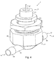
- the sensor 3 comprises a temperature probe 40, a sheath 41 enveloping said probe 40, an obturating lid 42 and a hollow screw 43 with a round flat head.
- the temperature probe 40 comprises a generally cylindrical body 45 onto which is screwed a head 46 in the form of a hexagonal nut.
- the body 45 and the head 46 of this probe 40 are hollow and each have an outer wall here of stainless steel.
- the head 46 accommodates a converging lens enabling a detection cone to be defined of which the point (corresponding to the focal point of that lens) is situated on the lid 42 when the sensor 3 is assembled.
- the body 45 houses a detector sensitive to infrared radiation as well as a processing device which converts the radiation captured by the sensor into a signal representing the temperature.
- the probe 40 also comprises a flexible cable 47 to enable it to be supplied with power and ensure the transmission of the signals sent by the processing device.
- the sheath 41 enveloping the probe comprises a cup 41a adapted to cooperate by screwing with a cap 41b
- the cup 41a comprises a cylindrical main wall 49 and a bottom wall 50.
- the bottom wall 50 has a circular opening 51 provided for the passage of the cable 47 of the probe 40.
- the cylindrical wall 49 has a screw thread 52 disposed on its outer face and at its opposite end to the bottom wall 50.
- the cap 41b comprises a breech 55 surmounted by a tapped collar 56 provided to cooperate with the screw thread 52.
- the back of the breech 55 forms a stiff plate 58 at the center of which a circular aperture 57 ( Figure 2 ) is formed to enable the passage of the infrared radiation towards the sensitive part of the detector of the probe 40.
- the breech 55 furthermore has the same outer diameter as that of the cylindrical wall 49 of the cup 41a, this outer diameter moreover being slightly less than that of the central bore 26 of the screw 8 of the connector 2.
- the obturating lid 42 is here formed from an opaque adhesive film (here of polyimide) of which the emissivity is constant in the temperature range from 4 to 40 degrees Celsius.
- This lid 42 of the same diameter as the plate 58, is bonded to the latter so as to completely cover the face of that plate 58 that is oriented towards the membrane 6.
- the screw 43 comprises a through bore 60 of which the diameter is very slightly greater than the outer diameter of the cylindrical wall 49 of the cup 41a such that the screw is adapted to slide along that cup 41a.
- the screw 43 has on its outer face and at its opposite end to its circular head 61, a screw thread 62 provided to cooperate with the tapping 27 of the connector 2.
- the assembly of the temperature sensor 3 is made in the following manner.
- the cup 41a is first of all engaged in the bore 60 of the screw 43, then the end of the cable 47 is inserted inside that cup 41a so as to make it come out by the opening 51.
- the probe 40 is disposed in the cup 41a and lastly the cap 41b is screwed onto that cup.
- the temperature sensor 3 is as illustrated in Figure 6 and is then adapted to be received partially in the connector 2.
- the senor 3 is disposed such that the lid 42 faces the membrane 6, and sensor 3 is inserted into the tapping 27 and the bore 26 of the connector 2.
- the probe 40 of the sensor 3 is powered via the cable 47.
- This radiation is converted by the processing device into a signal representing the temperature which is transmitted via the cable 47.
- a converging lens in the head 46 of the probe 40 enables the diameter of the aperture 57 to be limited in order for the lid 42 to have a maximum area in contact with the plate 58 of the breech 55, which is stiff.
- the lid 42 and the membrane 6 are thus stiffened by that plate 58 which avoids any risk of bursting of the membrane 6, even in the case of high pressure of the liquid flowing in the internal passage 13 of the connector 2.
- the analysis by the sensor 3 of the emission from that lid 42 enables the temperature thereof to be determined with improved precision in that the coefficient of emissivity of that lid is constant in the temperature range of interest here, i.e. between 4 and 40 degrees Celsius.
- the sensor 3 thus enables the temperature of the liquid flowing in the internal passage 13 to be determined, here with a precision of +/- 2 degrees.
- the senor does not comprise a lid, the temperature measurement being made directly on the membrane or through it.
- the senor does not comprise a wall, such as the plate 58, to stiffen the membrane (the pressure of the liquid flowing in the internal passage of the connector being low).
Applications Claiming Priority (2)
| Application Number | Priority Date | Filing Date | Title |
|---|---|---|---|
| FR0951600A FR2943134B1 (fr) | 2009-03-13 | 2009-03-13 | Dispositif pour determiner une grandeur physique d'un liquide circulant dans une conduite |
| EP10290121.2A EP2228635B1 (de) | 2009-03-13 | 2010-03-10 | Vorrichtung zur erfassung einer physikalischen grösse einer in einer leitung strömenden flüssigkeit |
Related Parent Applications (1)
| Application Number | Title | Priority Date | Filing Date |
|---|---|---|---|
| EP10290121.2A Division EP2228635B1 (de) | 2009-03-13 | 2010-03-10 | Vorrichtung zur erfassung einer physikalischen grösse einer in einer leitung strömenden flüssigkeit |
Publications (1)
| Publication Number | Publication Date |
|---|---|
| EP3869170A1 true EP3869170A1 (de) | 2021-08-25 |
Family
ID=41128243
Family Applications (2)
| Application Number | Title | Priority Date | Filing Date |
|---|---|---|---|
| EP10290121.2A Active EP2228635B1 (de) | 2009-03-13 | 2010-03-10 | Vorrichtung zur erfassung einer physikalischen grösse einer in einer leitung strömenden flüssigkeit |
| EP21169054.0A Pending EP3869170A1 (de) | 2009-03-13 | 2010-03-10 | Vorrichtung zur bestimmung des physikalischen wertes einer in einem rohr fliessenden flüssigkeit |
Family Applications Before (1)
| Application Number | Title | Priority Date | Filing Date |
|---|---|---|---|
| EP10290121.2A Active EP2228635B1 (de) | 2009-03-13 | 2010-03-10 | Vorrichtung zur erfassung einer physikalischen grösse einer in einer leitung strömenden flüssigkeit |
Country Status (9)
| Country | Link |
|---|---|
| US (2) | US8297128B2 (de) |
| EP (2) | EP2228635B1 (de) |
| JP (1) | JP5378256B2 (de) |
| CN (1) | CN101839776B (de) |
| BR (1) | BRPI1000554A2 (de) |
| ES (1) | ES2866298T3 (de) |
| FR (1) | FR2943134B1 (de) |
| SG (2) | SG165227A1 (de) |
| WO (1) | WO2010103470A1 (de) |
Families Citing this family (41)
| Publication number | Priority date | Publication date | Assignee | Title |
|---|---|---|---|---|
| US8640560B2 (en) | 2008-03-26 | 2014-02-04 | Emd Millipore Corporation | System and method for interfacing sensors to a sterile flow stream |
| FR2931838B1 (fr) | 2008-06-02 | 2010-06-11 | Millipore Corp | Installation pour traiter un liquide biologique. |
| FR2940145B1 (fr) | 2008-12-24 | 2011-03-25 | Millipore Corp | Chariot et installation de traitement d'un liquide biologique |
| FR2941385B1 (fr) | 2009-01-23 | 2011-04-01 | Millipore Corp | Procede pour fournir un circuit pour liquide biologique et circuit obtenu. |
| FR2943134B1 (fr) | 2009-03-13 | 2011-10-07 | Millipore Corp | Dispositif pour determiner une grandeur physique d'un liquide circulant dans une conduite |
| FR2955119B1 (fr) | 2010-01-13 | 2012-12-28 | Millipore Corp | Circuit pour liquide biologique |
| FR2960794B1 (fr) | 2010-06-08 | 2012-07-27 | Millipore Corp | Dispositif pour une installation de traitement de liquide biologique |
| FR2960796B1 (fr) | 2010-06-08 | 2014-01-24 | Millipore Corp | Dispositif pour une installation de traitement de liquide biologique |
| FR2960795B1 (fr) | 2010-06-08 | 2012-07-27 | Millipore Corp | Dispositif pour une installation de traitement de liquide biologique |
| FR2961711B1 (fr) | 2010-06-23 | 2012-08-17 | Millipore Corp | Poche pour circuit d'une installation de traitement de liquide biologique |
| FR2961713B1 (fr) | 2010-06-23 | 2012-08-10 | Millipore Corp | Poche pour circuit d'une installation de traitement de liquide biologique |
| FR2963573B1 (fr) | 2010-08-03 | 2012-08-31 | Millipore Corp | Chariot de pompage pour une installation de traitement de liquide biologique |
| JP2012086426A (ja) * | 2010-10-19 | 2012-05-10 | Seiko Epson Corp | 液体噴射ヘッドユニット |
| JP5669633B2 (ja) * | 2011-03-11 | 2015-02-12 | 三菱重工業株式会社 | センサ取付構造 |
| DE102012204709A1 (de) * | 2011-03-25 | 2012-09-27 | Meissner Filtration Products Inc. | Druckmessanschluss mit thermoplastisch elastomerischer Grenzfläche |
| FR2973396B1 (fr) | 2011-03-28 | 2013-05-10 | Millipore Corp | Installation de traitement de liquide biologique |
| WO2012177737A1 (en) * | 2011-06-21 | 2012-12-27 | Ohio University | Device and method for monitoring interaction between a fluid and a wall |
| DE102011080956A1 (de) * | 2011-07-25 | 2013-01-31 | Endress + Hauser Conducta Gesellschaft für Mess- und Regeltechnik mbH + Co. KG | Verfahren und Messstelle zur Messung zumindest einer physikalischen und/oder chemischen Prozessgrößen eines in einem Einwegbehältnis enthaltenen Messmediums |
| WO2014014483A1 (en) | 2012-07-18 | 2014-01-23 | Daniel Measurement And Control, Inc. | Method for forming a welded seal |
| FR2993572B1 (fr) | 2012-07-23 | 2016-04-15 | Emd Millipore Corp | Circuit pour liquide biologique comportant une vanne a pincement |
| JP6058337B2 (ja) * | 2012-09-28 | 2017-01-11 | 泉工医科工業株式会社 | 圧力センサ付きコネクタ |
| JP6636943B2 (ja) * | 2014-05-15 | 2020-01-29 | ノヴァラング ゲゼルシャフト ミット ベシュレンクテル ハフツング | 医療技術的測定装置、及び測定方法 |
| US20160003685A1 (en) * | 2014-07-03 | 2016-01-07 | Vareck Walla | Mounting Apparatus for Temperature Sensor |
| WO2016086043A1 (en) | 2014-11-24 | 2016-06-02 | Massachusetts Institute Of Technology | Methods and apparatus for spectral imaging |
| DE102015110259A1 (de) | 2015-06-25 | 2016-12-29 | Endress + Hauser Gmbh + Co. Kg | Drucksensormodul Messanordnung mit einem Drucksensormodul |
| WO2017019482A1 (en) | 2015-07-24 | 2017-02-02 | Massachusetts Institute Of Technology | Apparatus, systems, and methods for biomedical imaging and stimulation |
| US10006809B2 (en) | 2016-02-10 | 2018-06-26 | Massachusetts Institute Of Technology | Apparatus, systems, and methods for on-chip spectroscopy using optical switches |
| CN106197833B (zh) * | 2016-08-31 | 2022-04-29 | 佛山市云米电器科技有限公司 | 压力传感器 |
| CN106248292A (zh) * | 2016-08-31 | 2016-12-21 | 佛山市云米电器科技有限公司 | 带有无线功能的压力传感器及其智能设备和应用 |
| US10836990B2 (en) | 2016-12-23 | 2020-11-17 | Cyberoptics Corporation | Sensor interface for single-use containers |
| US20180231167A1 (en) * | 2017-02-16 | 2018-08-16 | Contitech Usa, Inc. | Temperature / pressure sensing via hose fitting assembly |
| JP2018163074A (ja) * | 2017-03-27 | 2018-10-18 | 日本電産トーソク株式会社 | 油圧センサ取付構造 |
| JP6838461B2 (ja) * | 2017-03-30 | 2021-03-03 | 日本電産トーソク株式会社 | 油圧センサ取付構造 |
| JP6857095B2 (ja) | 2017-07-05 | 2021-04-14 | サーパス工業株式会社 | 圧力検出装置 |
| US10718668B2 (en) | 2017-08-08 | 2020-07-21 | Massachusetts Institute Of Technology | Miniaturized Fourier-transform Raman spectrometer systems and methods |
| WO2019035073A2 (en) | 2017-08-18 | 2019-02-21 | Abbott Diabetes Care Inc. | SYSTEMS, DEVICES AND METHODS RELATING TO INDIVIDUALIZED CALIBRATION AND / OR MANUFACTURING OF MEDICAL DEVICES |
| EP3669134B1 (de) * | 2017-10-23 | 2021-11-03 | Stoneage, Inc. | Datenlogger-vorrichtung und system für eine hochdruckreinigungslanzenantriebsvorrichtung |
| US10970614B2 (en) * | 2018-06-21 | 2021-04-06 | Rosemount Inc. | Single-use pressure transducer disposable interface |
| US11041759B2 (en) | 2018-06-28 | 2021-06-22 | Massachusetts Institute Of Technology | Systems and methods for Raman spectroscopy |
| WO2020167370A1 (en) | 2019-02-11 | 2020-08-20 | Massachusetts Institute Of Technology | High-performance on-chip spectrometers and spectrum analyzers |
| TWI806157B (zh) * | 2021-09-13 | 2023-06-21 | 英業達股份有限公司 | 液冷迴路中測量液體溫度的方法 |
Citations (6)
| Publication number | Priority date | Publication date | Assignee | Title |
|---|---|---|---|---|
| US4141252A (en) * | 1977-11-04 | 1979-02-27 | Lodge Arthur S | Flush pressure transducers for measuring pressures in a flowing fluid |
| JPH0428347A (ja) * | 1990-05-23 | 1992-01-30 | Terumo Corp | 管路及びプローブとそれらを備える流体情報測定装置 |
| EP0980686A2 (de) * | 1998-08-19 | 2000-02-23 | Fresenius Medical Care Deutschland GmbH | Multifunktionssensor |
| EP1287839A2 (de) * | 2001-09-03 | 2003-03-05 | Fresenius Medical Care Deutschland GmbH | Messvorrichtung und -verfahren zur Bestimmung von Parametern medizinischer Flüssigkeiten |
| DE10345299B3 (de) * | 2003-09-30 | 2005-07-21 | Giese, Erhard, Dr. | Druck/Temperatur-Sensor |
| EP1658869A1 (de) * | 2004-11-17 | 2006-05-24 | Fresenius Medical Care Deutschland GmbH | Membraneinheit, Gehäuse einer Druckmesseinheit und Druckmesseinheit |
Family Cites Families (34)
| Publication number | Priority date | Publication date | Assignee | Title |
|---|---|---|---|---|
| NO125760B (de) * | 1971-02-17 | 1972-10-30 | Sentralinst For Ind Forskning | |
| GB1365769A (en) | 1972-03-11 | 1974-09-04 | Mardon Flexible Packagaing Ltd | Heat sealed package |
| US4463593A (en) * | 1980-11-11 | 1984-08-07 | G. D. Searle & Co. | Apparatus for monitoring the partial pressure of gases |
| US4415858A (en) * | 1981-06-12 | 1983-11-15 | The United States Of America As Represented By The United States Department Of Energy | pH Meter probe assembly |
| US4786474A (en) * | 1983-10-28 | 1988-11-22 | Cardiovascular Devices, Inc. | Flow-through housing |
| JPS60102003U (ja) * | 1983-12-17 | 1985-07-11 | テルモ株式会社 | 体外血液循環回路用器具 |
| DE3516080A1 (de) * | 1985-05-04 | 1986-11-06 | Proton AG, Zug | Probeentnahmesonde |
| US4700560A (en) * | 1985-05-22 | 1987-10-20 | American Hospital Supply Corporation | Calibration cell for calibration of gaseous or non-gaseous fluid constituent sensors |
| DE8711127U1 (de) * | 1987-08-17 | 1987-10-22 | Pfeifer, Heidemarie, 8756 Kahl, De | |
| US5178267A (en) * | 1990-12-20 | 1993-01-12 | Abbott Laboratories | Packaging system for a sterilizable calbratable medical device |
| DE4419593A1 (de) * | 1994-06-03 | 1995-12-07 | Fresenius Ag | Vorrichtung zum Messen des Drucks eines Mediums |
| FR2724321A1 (fr) * | 1994-09-14 | 1996-03-15 | Hospal Ind | Dispositif de mesure de la pression d'un liquide et procede de reglage d'un tel dispositif |
| US5697366A (en) * | 1995-01-27 | 1997-12-16 | Optical Sensors Incorporated | In situ calibration system for sensors located in a physiologic line |
| DE10051220A1 (de) | 2000-10-16 | 2002-04-25 | Mettler Toledo Gmbh | Optischer Sensor zur Bestimmung eines Analyten und Verfahren zu dessen Herstellung |
| DE10116614C5 (de) * | 2001-04-03 | 2008-10-16 | Endress + Hauser Conducta Gesellschaft für Mess- und Regeltechnik mbH + Co. KG | Automatisierbare Meß-, Reinigungs- und Kalibriereinrichtung für pH-Elektroden oder Elektroden zur Messung von Redoxpotentialen |
| US6883377B2 (en) * | 2001-06-14 | 2005-04-26 | Regulateurs Georgin | Measurement device including a pressure sensor |
| ITMI20012828A1 (it) * | 2001-12-28 | 2003-06-28 | Gambro Dasco Spa | Dispositivo non invasivo per il rilevamento della temperatura ematicain un circuito per la circolazione extracorporea del sangue e apparato |
| US7021148B2 (en) | 2002-04-30 | 2006-04-04 | Baxter International Inc. | Apparatus and method for sealing pressure sensor membranes |
| DE102004033303A1 (de) * | 2004-04-16 | 2005-11-03 | Endress + Hauser Conducta Gesellschaft für Mess- und Regeltechnik mbH + Co. KG | Vorrichtung zur Bestimmung und/oder Überwachung eines in einem fluiden Prozessmedium enthaltenen Analyten |
| DE102005051279B4 (de) * | 2005-10-26 | 2008-05-21 | Endress + Hauser Conducta Gmbh + Co. Kg | Armatur zur Aufnahme einer Messsonde |
| DE102006005533B4 (de) * | 2006-02-07 | 2008-04-17 | Sartorius Stedim Biotech Gmbh | Verbindersystem und Verfahren zum sterilen Verbinden |
| DE102006022307A1 (de) | 2006-05-11 | 2007-11-15 | Respironics Novametrix, LLC, Wallingford | Einwegbioreaktor mit Sensoranordnung |
| US7470060B1 (en) * | 2006-06-23 | 2008-12-30 | Innovative Measurement Methods, Inc. | Detection apparatus for measuring fluid in a vessel |
| EP2044438B1 (de) * | 2006-07-24 | 2017-11-01 | Biocer-Entwicklungs-GmbH | Anordnung für online-messungen an zellen |
| US7540197B2 (en) * | 2006-12-01 | 2009-06-02 | Luna Innovations Incorporated | Sensors, methods and systems for determining physical effects of a fluid |
| US7661294B2 (en) * | 2007-09-21 | 2010-02-16 | Cosense, Inc. | Non-invasive multi-function sensor system |
| US20090101213A1 (en) * | 2007-10-19 | 2009-04-23 | Rivatek, Inc. | Apparatus for controlling and metering fluid flow |
| US8640560B2 (en) * | 2008-03-26 | 2014-02-04 | Emd Millipore Corporation | System and method for interfacing sensors to a sterile flow stream |
| US8250924B2 (en) * | 2008-04-22 | 2012-08-28 | Rosemount Inc. | Industrial process device utilizing piezoelectric transducer |
| RU2453931C1 (ru) * | 2008-05-27 | 2012-06-20 | Роузмаунт, Инк. | Улучшенная компенсация температуры многопараметрического датчика давления |
| US7918134B2 (en) * | 2008-10-06 | 2011-04-05 | Rosemount Inc. | Thermal-based diagnostic system for process transmitter |
| US8387463B2 (en) * | 2008-10-06 | 2013-03-05 | Rosemount Inc. | Pressure-based diagnostic system for process transmitter |
| EP2226087A1 (de) | 2009-03-06 | 2010-09-08 | Fresenius Medical Care Deutschland G.M.B.H. | Sicherheitseinsatz für extrakorporale Schaltungen |
| FR2943134B1 (fr) | 2009-03-13 | 2011-10-07 | Millipore Corp | Dispositif pour determiner une grandeur physique d'un liquide circulant dans une conduite |
-
2009
- 2009-03-13 FR FR0951600A patent/FR2943134B1/fr active Active
-
2010
- 2010-02-02 US US12/698,624 patent/US8297128B2/en active Active
- 2010-02-03 SG SG201000751-6A patent/SG165227A1/en unknown
- 2010-02-03 SG SG2014008593A patent/SG2014008593A/en unknown
- 2010-02-05 JP JP2010023784A patent/JP5378256B2/ja active Active
- 2010-03-09 BR BRPI1000554-4A patent/BRPI1000554A2/pt not_active Application Discontinuation
- 2010-03-10 EP EP10290121.2A patent/EP2228635B1/de active Active
- 2010-03-10 ES ES10290121T patent/ES2866298T3/es active Active
- 2010-03-10 EP EP21169054.0A patent/EP3869170A1/de active Pending
- 2010-03-10 WO PCT/IB2010/051032 patent/WO2010103470A1/en active Application Filing
- 2010-03-11 CN CN201010136775.3A patent/CN101839776B/zh active Active
-
2012
- 2012-09-07 US US13/606,389 patent/US8485044B2/en active Active
Patent Citations (6)
| Publication number | Priority date | Publication date | Assignee | Title |
|---|---|---|---|---|
| US4141252A (en) * | 1977-11-04 | 1979-02-27 | Lodge Arthur S | Flush pressure transducers for measuring pressures in a flowing fluid |
| JPH0428347A (ja) * | 1990-05-23 | 1992-01-30 | Terumo Corp | 管路及びプローブとそれらを備える流体情報測定装置 |
| EP0980686A2 (de) * | 1998-08-19 | 2000-02-23 | Fresenius Medical Care Deutschland GmbH | Multifunktionssensor |
| EP1287839A2 (de) * | 2001-09-03 | 2003-03-05 | Fresenius Medical Care Deutschland GmbH | Messvorrichtung und -verfahren zur Bestimmung von Parametern medizinischer Flüssigkeiten |
| DE10345299B3 (de) * | 2003-09-30 | 2005-07-21 | Giese, Erhard, Dr. | Druck/Temperatur-Sensor |
| EP1658869A1 (de) * | 2004-11-17 | 2006-05-24 | Fresenius Medical Care Deutschland GmbH | Membraneinheit, Gehäuse einer Druckmesseinheit und Druckmesseinheit |
Also Published As
| Publication number | Publication date |
|---|---|
| US8485044B2 (en) | 2013-07-16 |
| SG2014008593A (en) | 2014-04-28 |
| BRPI1000554A2 (pt) | 2011-03-22 |
| CN101839776B (zh) | 2014-06-11 |
| EP2228635A1 (de) | 2010-09-15 |
| JP5378256B2 (ja) | 2013-12-25 |
| CN101839776A (zh) | 2010-09-22 |
| SG165227A1 (en) | 2010-10-28 |
| US20130003780A1 (en) | 2013-01-03 |
| US20110041619A1 (en) | 2011-02-24 |
| ES2866298T3 (es) | 2021-10-19 |
| WO2010103470A1 (en) | 2010-09-16 |
| US8297128B2 (en) | 2012-10-30 |
| EP2228635B1 (de) | 2021-04-21 |
| FR2943134A1 (fr) | 2010-09-17 |
| FR2943134B1 (fr) | 2011-10-07 |
| JP2010223946A (ja) | 2010-10-07 |
Similar Documents
| Publication | Publication Date | Title |
|---|---|---|
| US8485044B2 (en) | Device for determining a physical value of a liquid flowing in a pipe | |
| US7694570B1 (en) | Non-invasive dry coupled disposable/reusable ultrasonic sensor | |
| US9140613B2 (en) | Superheat sensor | |
| CN108240831B (zh) | 用于一次性容器的传感器接口 | |
| US20130205907A1 (en) | Pressure detector | |
| NZ620811A (en) | Point-of-care fluidic systems and uses thereof | |
| CA2740932A1 (en) | Infrared temperature measurement of strip | |
| CN101273884B (zh) | 耳式体温计 | |
| JP7021229B2 (ja) | 調節可能なばねが装備された温度センサ用アダプタ | |
| CN100526827C (zh) | 用于自动放气泄漏检测器的测试漏气装置 | |
| KR102612893B1 (ko) | 압력 검출 장치 | |
| CN106996808B (zh) | 流量测量器 | |
| JP6632902B2 (ja) | 圧力検出装置 | |
| CN105628293B (zh) | 压力传感器 | |
| US9766147B2 (en) | Pressure sensor including leakage detection part for detecting leakage of liquid | |
| KR20200001515A (ko) | 물리량 측정 장치 | |
| JP2006058231A (ja) | 温度計 | |
| CN107397444B (zh) | 煲盖和烹饪锅具 | |
| US20200049537A1 (en) | Housing for a field device in measuring and automation technology for monitoring and/or determining at least one process variable of a medium | |
| EP0857956A1 (de) | Temperaturmessgerät | |
| CN210294302U (zh) | 光电倍增管及光检测设备 | |
| JP2016205877A (ja) | 圧力検出器 | |
| JP2009019980A (ja) | 井戸の液位・液深測定装置 | |
| CN105158294A (zh) | 一种用摄像头测定露点的装置 |
Legal Events
| Date | Code | Title | Description |
|---|---|---|---|
| PUAI | Public reference made under article 153(3) epc to a published international application that has entered the european phase |
Free format text: ORIGINAL CODE: 0009012 |
|
| STAA | Information on the status of an ep patent application or granted ep patent |
Free format text: STATUS: THE APPLICATION HAS BEEN PUBLISHED |
|
| AC | Divisional application: reference to earlier application |
Ref document number: 2228635 Country of ref document: EP Kind code of ref document: P |
|
| AK | Designated contracting states |
Kind code of ref document: A1 Designated state(s): AT BE BG CH CY CZ DE DK EE ES FI FR GB GR HR HU IE IS IT LI LT LU LV MC MK MT NL NO PL PT RO SE SI SK SM TR |
|
| STAA | Information on the status of an ep patent application or granted ep patent |
Free format text: STATUS: REQUEST FOR EXAMINATION WAS MADE |
|
| 17P | Request for examination filed |
Effective date: 20220211 |
|
| RBV | Designated contracting states (corrected) |
Designated state(s): AT BE BG CH CY CZ DE DK EE ES FI FR GB GR HR HU IE IS IT LI LT LU LV MC MK MT NL NO PL PT RO SE SI SK SM TR |
|
| STAA | Information on the status of an ep patent application or granted ep patent |
Free format text: STATUS: EXAMINATION IS IN PROGRESS |
|
| 17Q | First examination report despatched |
Effective date: 20230607 |
|
| P01 | Opt-out of the competence of the unified patent court (upc) registered |
Effective date: 20230602 |