EP3865203B1 - Gas turbine combined cycle power generation system, and exhaust gas treatment method - Google Patents
Gas turbine combined cycle power generation system, and exhaust gas treatment method Download PDFInfo
- Publication number
- EP3865203B1 EP3865203B1 EP21159439.5A EP21159439A EP3865203B1 EP 3865203 B1 EP3865203 B1 EP 3865203B1 EP 21159439 A EP21159439 A EP 21159439A EP 3865203 B1 EP3865203 B1 EP 3865203B1
- Authority
- EP
- European Patent Office
- Prior art keywords
- exhaust gas
- gas treatment
- turbine
- site
- composite oxide
- Prior art date
- Legal status (The legal status is an assumption and is not a legal conclusion. Google has not performed a legal analysis and makes no representation as to the accuracy of the status listed.)
- Active
Links
Images


Classifications
-
- B—PERFORMING OPERATIONS; TRANSPORTING
- B01—PHYSICAL OR CHEMICAL PROCESSES OR APPARATUS IN GENERAL
- B01D—SEPARATION
- B01D53/00—Separation of gases or vapours; Recovering vapours of volatile solvents from gases; Chemical or biological purification of waste gases, e.g. engine exhaust gases, smoke, fumes, flue gases, aerosols
- B01D53/34—Chemical or biological purification of waste gases
- B01D53/92—Chemical or biological purification of waste gases of engine exhaust gases
- B01D53/94—Chemical or biological purification of waste gases of engine exhaust gases by catalytic processes
- B01D53/944—Simultaneously removing carbon monoxide, hydrocarbons or carbon making use of oxidation catalysts
-
- B—PERFORMING OPERATIONS; TRANSPORTING
- B01—PHYSICAL OR CHEMICAL PROCESSES OR APPARATUS IN GENERAL
- B01D—SEPARATION
- B01D53/00—Separation of gases or vapours; Recovering vapours of volatile solvents from gases; Chemical or biological purification of waste gases, e.g. engine exhaust gases, smoke, fumes, flue gases, aerosols
- B01D53/34—Chemical or biological purification of waste gases
- B01D53/74—General processes for purification of waste gases; Apparatus or devices specially adapted therefor
- B01D53/86—Catalytic processes
- B01D53/8668—Removing organic compounds not provided for in B01D53/8603 - B01D53/8665
-
- B—PERFORMING OPERATIONS; TRANSPORTING
- B01—PHYSICAL OR CHEMICAL PROCESSES OR APPARATUS IN GENERAL
- B01D—SEPARATION
- B01D53/00—Separation of gases or vapours; Recovering vapours of volatile solvents from gases; Chemical or biological purification of waste gases, e.g. engine exhaust gases, smoke, fumes, flue gases, aerosols
- B01D53/34—Chemical or biological purification of waste gases
- B01D53/74—General processes for purification of waste gases; Apparatus or devices specially adapted therefor
- B01D53/86—Catalytic processes
-
- B—PERFORMING OPERATIONS; TRANSPORTING
- B01—PHYSICAL OR CHEMICAL PROCESSES OR APPARATUS IN GENERAL
- B01J—CHEMICAL OR PHYSICAL PROCESSES, e.g. CATALYSIS OR COLLOID CHEMISTRY; THEIR RELEVANT APPARATUS
- B01J23/00—Catalysts comprising metals or metal oxides or hydroxides, not provided for in group B01J21/00
- B01J23/002—Mixed oxides other than spinels, e.g. perovskite
-
- B—PERFORMING OPERATIONS; TRANSPORTING
- B01—PHYSICAL OR CHEMICAL PROCESSES OR APPARATUS IN GENERAL
- B01J—CHEMICAL OR PHYSICAL PROCESSES, e.g. CATALYSIS OR COLLOID CHEMISTRY; THEIR RELEVANT APPARATUS
- B01J23/00—Catalysts comprising metals or metal oxides or hydroxides, not provided for in group B01J21/00
- B01J23/38—Catalysts comprising metals or metal oxides or hydroxides, not provided for in group B01J21/00 of noble metals
- B01J23/54—Catalysts comprising metals or metal oxides or hydroxides, not provided for in group B01J21/00 of noble metals combined with metals, oxides or hydroxides provided for in groups B01J23/02 - B01J23/36
- B01J23/66—Silver or gold
- B01J23/68—Silver or gold with arsenic, antimony, bismuth, vanadium, niobium, tantalum, polonium, chromium, molybdenum, tungsten, manganese, technetium or rhenium
- B01J23/688—Silver or gold with arsenic, antimony, bismuth, vanadium, niobium, tantalum, polonium, chromium, molybdenum, tungsten, manganese, technetium or rhenium with manganese, technetium or rhenium
-
- B—PERFORMING OPERATIONS; TRANSPORTING
- B01—PHYSICAL OR CHEMICAL PROCESSES OR APPARATUS IN GENERAL
- B01J—CHEMICAL OR PHYSICAL PROCESSES, e.g. CATALYSIS OR COLLOID CHEMISTRY; THEIR RELEVANT APPARATUS
- B01J37/00—Processes, in general, for preparing catalysts; Processes, in general, for activation of catalysts
- B01J37/04—Mixing
-
- B—PERFORMING OPERATIONS; TRANSPORTING
- B01—PHYSICAL OR CHEMICAL PROCESSES OR APPARATUS IN GENERAL
- B01J—CHEMICAL OR PHYSICAL PROCESSES, e.g. CATALYSIS OR COLLOID CHEMISTRY; THEIR RELEVANT APPARATUS
- B01J37/00—Processes, in general, for preparing catalysts; Processes, in general, for activation of catalysts
- B01J37/08—Heat treatment
-
- F—MECHANICAL ENGINEERING; LIGHTING; HEATING; WEAPONS; BLASTING
- F01—MACHINES OR ENGINES IN GENERAL; ENGINE PLANTS IN GENERAL; STEAM ENGINES
- F01K—STEAM ENGINE PLANTS; STEAM ACCUMULATORS; ENGINE PLANTS NOT OTHERWISE PROVIDED FOR; ENGINES USING SPECIAL WORKING FLUIDS OR CYCLES
- F01K23/00—Plants characterised by more than one engine delivering power external to the plant, the engines being driven by different fluids
- F01K23/02—Plants characterised by more than one engine delivering power external to the plant, the engines being driven by different fluids the engine cycles being thermally coupled
- F01K23/06—Plants characterised by more than one engine delivering power external to the plant, the engines being driven by different fluids the engine cycles being thermally coupled combustion heat from one cycle heating the fluid in another cycle
- F01K23/10—Plants characterised by more than one engine delivering power external to the plant, the engines being driven by different fluids the engine cycles being thermally coupled combustion heat from one cycle heating the fluid in another cycle with exhaust fluid of one cycle heating the fluid in another cycle
-
- F—MECHANICAL ENGINEERING; LIGHTING; HEATING; WEAPONS; BLASTING
- F01—MACHINES OR ENGINES IN GENERAL; ENGINE PLANTS IN GENERAL; STEAM ENGINES
- F01N—GAS-FLOW SILENCERS OR EXHAUST APPARATUS FOR MACHINES OR ENGINES IN GENERAL; GAS-FLOW SILENCERS OR EXHAUST APPARATUS FOR INTERNAL-COMBUSTION ENGINES
- F01N3/00—Exhaust or silencing apparatus having means for purifying, rendering innocuous, or otherwise treating exhaust
- F01N3/08—Exhaust or silencing apparatus having means for purifying, rendering innocuous, or otherwise treating exhaust for rendering innocuous
- F01N3/10—Exhaust or silencing apparatus having means for purifying, rendering innocuous, or otherwise treating exhaust for rendering innocuous by thermal or catalytic conversion of noxious components of exhaust
- F01N3/18—Exhaust or silencing apparatus having means for purifying, rendering innocuous, or otherwise treating exhaust for rendering innocuous by thermal or catalytic conversion of noxious components of exhaust characterised by methods of operation; Control
- F01N3/20—Exhaust or silencing apparatus having means for purifying, rendering innocuous, or otherwise treating exhaust for rendering innocuous by thermal or catalytic conversion of noxious components of exhaust characterised by methods of operation; Control specially adapted for catalytic conversion
-
- F—MECHANICAL ENGINEERING; LIGHTING; HEATING; WEAPONS; BLASTING
- F23—COMBUSTION APPARATUS; COMBUSTION PROCESSES
- F23G—CREMATION FURNACES; CONSUMING WASTE PRODUCTS BY COMBUSTION
- F23G7/00—Incinerators or other apparatus for consuming industrial waste, e.g. chemicals
- F23G7/06—Incinerators or other apparatus for consuming industrial waste, e.g. chemicals of waste gases or noxious gases, e.g. exhaust gases
- F23G7/07—Incinerators or other apparatus for consuming industrial waste, e.g. chemicals of waste gases or noxious gases, e.g. exhaust gases in which combustion takes place in the presence of catalytic material
-
- F—MECHANICAL ENGINEERING; LIGHTING; HEATING; WEAPONS; BLASTING
- F23—COMBUSTION APPARATUS; COMBUSTION PROCESSES
- F23R—GENERATING COMBUSTION PRODUCTS OF HIGH PRESSURE OR HIGH VELOCITY, e.g. GAS-TURBINE COMBUSTION CHAMBERS
- F23R3/00—Continuous combustion chambers using liquid or gaseous fuel
- F23R3/40—Continuous combustion chambers using liquid or gaseous fuel characterised by the use of catalytic means
-
- B—PERFORMING OPERATIONS; TRANSPORTING
- B01—PHYSICAL OR CHEMICAL PROCESSES OR APPARATUS IN GENERAL
- B01D—SEPARATION
- B01D2255/00—Catalysts
- B01D2255/10—Noble metals or compounds thereof
- B01D2255/104—Silver
-
- B—PERFORMING OPERATIONS; TRANSPORTING
- B01—PHYSICAL OR CHEMICAL PROCESSES OR APPARATUS IN GENERAL
- B01D—SEPARATION
- B01D2255/00—Catalysts
- B01D2255/20—Metals or compounds thereof
- B01D2255/206—Rare earth metals
-
- B—PERFORMING OPERATIONS; TRANSPORTING
- B01—PHYSICAL OR CHEMICAL PROCESSES OR APPARATUS IN GENERAL
- B01D—SEPARATION
- B01D2255/00—Catalysts
- B01D2255/20—Metals or compounds thereof
- B01D2255/207—Transition metals
- B01D2255/2073—Manganese
-
- B—PERFORMING OPERATIONS; TRANSPORTING
- B01—PHYSICAL OR CHEMICAL PROCESSES OR APPARATUS IN GENERAL
- B01D—SEPARATION
- B01D2255/00—Catalysts
- B01D2255/40—Mixed oxides
- B01D2255/402—Perovskites
-
- B—PERFORMING OPERATIONS; TRANSPORTING
- B01—PHYSICAL OR CHEMICAL PROCESSES OR APPARATUS IN GENERAL
- B01D—SEPARATION
- B01D2257/00—Components to be removed
- B01D2257/70—Organic compounds not provided for in groups B01D2257/00 - B01D2257/602
- B01D2257/708—Volatile organic compounds V.O.C.'s
-
- B—PERFORMING OPERATIONS; TRANSPORTING
- B01—PHYSICAL OR CHEMICAL PROCESSES OR APPARATUS IN GENERAL
- B01D—SEPARATION
- B01D2258/00—Sources of waste gases
- B01D2258/02—Other waste gases
- B01D2258/0283—Flue gases
-
- Y—GENERAL TAGGING OF NEW TECHNOLOGICAL DEVELOPMENTS; GENERAL TAGGING OF CROSS-SECTIONAL TECHNOLOGIES SPANNING OVER SEVERAL SECTIONS OF THE IPC; TECHNICAL SUBJECTS COVERED BY FORMER USPC CROSS-REFERENCE ART COLLECTIONS [XRACs] AND DIGESTS
- Y02—TECHNOLOGIES OR APPLICATIONS FOR MITIGATION OR ADAPTATION AGAINST CLIMATE CHANGE
- Y02E—REDUCTION OF GREENHOUSE GAS [GHG] EMISSIONS, RELATED TO ENERGY GENERATION, TRANSMISSION OR DISTRIBUTION
- Y02E20/00—Combustion technologies with mitigation potential
- Y02E20/12—Heat utilisation in combustion or incineration of waste
-
- Y—GENERAL TAGGING OF NEW TECHNOLOGICAL DEVELOPMENTS; GENERAL TAGGING OF CROSS-SECTIONAL TECHNOLOGIES SPANNING OVER SEVERAL SECTIONS OF THE IPC; TECHNICAL SUBJECTS COVERED BY FORMER USPC CROSS-REFERENCE ART COLLECTIONS [XRACs] AND DIGESTS
- Y02—TECHNOLOGIES OR APPLICATIONS FOR MITIGATION OR ADAPTATION AGAINST CLIMATE CHANGE
- Y02E—REDUCTION OF GREENHOUSE GAS [GHG] EMISSIONS, RELATED TO ENERGY GENERATION, TRANSMISSION OR DISTRIBUTION
- Y02E20/00—Combustion technologies with mitigation potential
- Y02E20/16—Combined cycle power plant [CCPP], or combined cycle gas turbine [CCGT]
Definitions
- the present invention relates to a gas turbine combined cycle power generation system and an exhaust gas treatment method.
- a platinum-supported alumina is used as a catalyst for oxidation removal of aldehyde, which is a non-combusted product of fuel, formaldehyde in particular, from exhaust gas of a gas turbine or a gas engine.
- Patent Document 2 discloses an oxidation catalyst having a composition expressed by a general expression Y 1-x Ag x MnO 3 (0.01 ⁇ x ⁇ 0.15), as an oxidation catalyst for oxidizing contents of exhaust gas of an internal combustion engine, such as particulates or high-boiling carbon hydrate.
- Patent Document 3 discloses a catalyst comprising a porous solid of a mixture of a composite metal oxide having a composition expressed by a general expression Y 0.95 Ag 0.05 MnO 3 and oxidized zirconium, as an oxidation catalyst for oxidizing particulates contained in exhaust gas of an internal combustion engine.
- Patent Document 4 discloses an exhaust gas aftertreatment system for treating exhaust gas discharged from a gas turbine system, the exhaust gas aftertreatment system comprising an oxidation catalyst, an ammonia injection apparatus, and a selective catalytic reduction catalyst for removing NOx.
- a catalyst of platinum-supported alumina is costly for platinum is expensive, and it is desirable to develop another catalyst capable of removing volatile organic compound (VOC) such as formaldehyde.
- VOC volatile organic compound
- Patent Documents 2 and 3 do not mention the function of a composite oxide containing Y and Ag to remove formaldehyde.
- An object of the present invention is to provide a gas turbine combined cycle power generation system and an exhaust gas treatment method having an excellent VOC removing performance.
- the present inventors conducted various researches to develop a novel exhaust gas treatment catalyst having an excellent performance of oxidizing VOC, formaldehyde in particular, to find that Ag (silver) and Dy (dysprosium) are promising as the elements of A site, and arrived at the present invention.
- the present invention is defined by the claims.
- the present invention thus relates to a gas turbine combined cycle power generation system as defined in claim 1.
- the gas turbine combined cycle power generation system comprises:
- the exhaust gas treatment device removes VOC from exhaust gas, while heat of exhaust gas is supplied to steam, and thereby it is possible to generate power by utilizing power of a steam turbine.
- the exhaust gas treatment device includes a perovskite composite oxide which is highly active under a low temperature, it is possible to remove VOC efficiently even if exhaust gas has a low temperature during startup of a gas turbine combined cycle power generation system. Furthermore, a perovskite composite oxide containing at least Ag and Dy in the A site and at least Mn in the B site has an excellent low-temperature activation property. Thus, the temperature of exhaust gas may decrease more than typical art at a heat exchanger upstream of the exhaust gas treatment catalyst in the flow direction of exhaust gas. Thus, while heating steam with high efficiency by utilizing high-temperature exhaust gas, it is possible to remove VOC from low-temperature exhaust gas efficiently.
- the gas turbine combined cycle power generation system discharges low-VOC exhaust gas from the exhaust gas treatment device, and has a high thermal efficiency, thus being environmentally friendly.
- the present invention relates to a method of treating exhaust gas as defined in claim 3.
- the exhaust gas treatment method comprises:
- the exhaust gas treatment method includes a step of causing exhaust gas to contact an exhaust gas treatment catalyst which includes a perovskite composite oxide containing at least Ag and Dy in the A site, and at least Mn in the B site, and thus has a high performance of oxidization removal of VOC such as formaldehyde.
- a perovskite composite oxide containing at least Ag and Dy in the A site and at least Mn in the B site has a higher VOC removing performance at a low temperature than a catalyst of platinum-supported alumina.
- the exhaust gas treatment method further comprises a heat exchange step of recovering heat of the exhaust gas by causing the exhaust gas discharged from the gas turbine to make contact with a heat exchanger, before the exhaust gas treatment step.
- a perovskite composite oxide containing at least Ag and Dy in the A site and at least Mn in the B site has an excellent low-temperature activation property.
- the temperature of exhaust gas may decrease more than typical art in the heat exchange step.
- a gas turbine combined cycle power generation system and an exhaust gas treatment method having an excellent VOC removing performance.
- an expression of relative or absolute arrangement such as “in a direction”, “along a direction”, “parallel”, “orthogonal”, “centered”, “concentric” and “coaxial” shall not be construed as indicating only the arrangement in a strict literal sense, but also includes a state where the arrangement is relatively displaced by a tolerance, or by an angle or a distance whereby it is possible to achieve the same function.
- an expression of an equal state such as “same” “equal” and “uniform” shall not be construed as indicating only the state in which the feature is strictly equal, but also includes a state in which there is a tolerance or a difference that can still achieve the same function.
- an expression of a shape such as a rectangular shape or a cylindrical shape shall not be construed as only the geometrically strict shape, but also includes a shape with unevenness or chamfered corners within the range in which the same effect can be achieved.
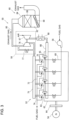
- FIG 1 is a schematic configuration diagram of a gas turbine combined cycle (GTCC) power generation system according to an embodiment of the present invention.
- GTCC gas turbine combined cycle
- the GTCC power generation system 1 is a combined power generation system, including a gas turbine 2, a steam turbine 3, a waste heat recovery boiler 5, and generators 7, 9.
- the GTCC power generation system may be for business use or home use.
- the gas turbine 2 includes a compressor 11, a combustor 13, and a turbine 15.
- the compressor 11 compresses air by utilizing a part of the output of the turbine 15, and compressed air is supplied to the combustor 13.
- the combustor 13 is supplied with compressed air and fuel, and fuel is combusted. Combustion gas produced by combustion of fuel is supplied to the turbine 15, and the turbine 15 outputs power by utilizing combustion gas.
- the turbine 15 is connected to the generator 7, and the generator 7 generates power by utilizing a part of the power of the turbine 15.
- Combustion gas (hereinafter, also referred to as exhaust gas) having performed work in the turbine 15 is supplied to the waste heat recovery boiler 5.
- the waste heat recovery boiler 5 serves as an exhaust gas treatment device for treating and purifying exhaust gas, and also as a heat exchanging device for generating steam by utilizing heat (waste heat) of exhaust gas.
- the waste heat recovery boiler 5 includes a housing 17 having an exhaust gas flow passage 16 inside thereof, an economizer 18, a header 19, an evaporator 21, a super-heater 23, and a re-heater 25.
- the economizer 18, the evaporator 21, the super-heater 23, and the re-heater 25 are disposed in the exhaust gas flow passage 16, serving as a heat exchanger that performs heat exchange between exhaust gas and water (steam). Water is heated by the economizer 18, the evaporator 21, and the re-heater 23, and thereby superheated steam is obtained.
- the waste heat recovery boiler 5 includes an oxidation catalyst device 27 and a denitration device 29 disposed in the exhaust gas flow passage 16 inside the housing 17, serving as an exhaust gas treatment device for purifying exhaust gas that flows through the exhaust gas flow passage 16.
- the denitration device 29 includes a selective catalytic reduction (SCR) catalyst, and has a function to remove NOx from exhaust gas.
- SCR selective catalytic reduction
- Superheated steam produced by the waste heat recovery boiler 5 is supplied to the steam turbine 3.
- the steam turbine 3 is connected to the generator 9 and outputs power by utilizing steam.
- the generator 9 generates power by utilizing the power of the steam turbine 3.
- the steam turbine 3 includes a high-pressure turbine 31, a mid-pressure turbine 33, and a low-pressure turbine 35.
- Each of the high-pressure turbine 31, the mid-pressure turbine 33, and the low-pressure turbine 35 outputs power by utilizing steam.
- the superheated steam performs work in the high-pressure turbine 31, and is temporarily returned to the waste heat recovery boiler 5, before being supplied to the re-heater 25.
- the re-heater 25 heats steam, and the heated steam is supplied to the mid-pressure turbine 33 of the steam turbine 3.
- a condenser 37 is connected to the low-pressure turbine 35, and the steam discharged from the low-pressure turbine 35 of the steam turbine 3 is condensed by the condenser 37 to turn into water.
- the condenser 37 is connected to the waste heat recovery boiler 5 via a condenser pump 39, and the condenser pump 39 supplies water obtained by the condenser 37 to the economizer 18 of the waste heat recovery boiler 5.
- the above described oxidation catalyst device 27 of the waste heat recovery boiler is disposed in a section of the exhaust gas flow passage 16 extending between the re-heater 25 and the super-heater 23, for instance.
- the oxidation catalyst device 27 includes a carrier and a catalyst supported by the carrier (hereinafter, the catalyst is also referred to as an oxidation catalyst or an exhaust gas treatment catalyst).
- the carrier has a metal or ceramic honeycomb structure.
- the oxidation catalyst includes a perovskite composite oxide containing at least Ag (silver) and Dy (dysprosium) in the A site, and at least Mn (manganese) in the B site. If the perovskite composite oxide has the cubical crystal system, the A site is positioned at the corner of a unit cell, the B site at the body center of the unit cell, and oxygen at the plane center of the unit cell.
- the crystal system is not limited to cubical.
- the waste heat recovery boiler 5 which is the exhaust gas treatment device for the above described GTCC power generation system 1, has an exhaust gas treatment catalyst which includes a perovskite composite oxide containing at least Ag and Dy in the A site, and at least Mn in the B site, and thus has a high performance of oxidization removal of VOC such as formaldehyde.
- a perovskite composite oxide containing at least Ag and Dy in the A site and at least Mn in the B site has a higher VOC removing performance at a low temperature than a catalyst of platinum-supported alumina.
- the waste heat recovery boiler 5 is less expensive than an exhaust gas treatment device including platinum as a main precious metal component.
- the gas turbine 2 is of a large type for power generation, the waste heat recovery boiler 5 requires a great amount of precious metal, and thus it is extremely advantageous to use Ag instead of Pt as a precious metal in terms of price.
- the above described waste heat recovery boiler 5 can utilize heat of exhaust gas by recovering heat of exhaust gas with a heat exchanger.
- a perovskite composite oxide containing at least Ag and Dy in the A site and at least Mn in the B site has an excellent low-temperature activation property.
- the temperature of exhaust gas may decrease more than typical art at a heat exchanger upstream of the oxidation catalyst device 27 in the flow direction of exhaust gas.
- heating steam with high efficiency by utilizing high-temperature exhaust gas it is possible to remove VOC from low-temperature exhaust gas efficiently.
- the GTCC power generation system 1 discharges low-VOC exhaust gas from the waste heat recovery boiler 5, and has a high thermal efficiency, thus being environmentally friendly.
- the oxidation catalyst device 27 is disposed in a section of the exhaust gas flow passage 16 extending between the re-heater 25 and the super-heater 23.
- the oxidation catalyst device 27 may be disposed in a section of the exhaust gas flow passage 16 extending between the re-heater 23 and the evaporator 21.
- FIG 2 is a schematic flowchart of an example of steps of an exhaust gas treatment method performed by the waste heat recovery boiler 5 of the GTCC power generation system in FIG 1 .
- the exhaust gas treatment method comprises a heat exchange step S1 of causing exhaust gas to contact the re-heater 25 serving as a heat exchanger and recovering heat of exhaust gas, and an exhaust gas treatment step S3 of causing exhaust gas to contact an exhaust gas treatment catalyst including a perovskite composite oxide containing at least Ag and Dy in the A site and at least Mn in the B site, after the heat exchange step S 1.
- the above described exhaust gas treatment method includes a step of causing exhaust gas to contact an exhaust gas treatment catalyst which includes a perovskite composite oxide containing at least Ag and Dy in the A site, and at least Mn in the B site, and thus has a high performance of oxidization removal of VOC such as formaldehyde.
- a perovskite composite oxide containing at least Ag and Dy in the A site and at least Mn in the B site has a higher VOC removing performance at a low temperature than a catalyst of platinum-supported alumina.
- a perovskite composite oxide containing at least Ag and Dy in the A site and at least Mn in the B site has an excellent low-temperature activation property.
- the temperature of exhaust gas may decrease more than typical art in the heat exchange step S1.
- FIG 3 is a schematic configuration diagram of a gas engine power generation system not covered by the present invention.
- the gas engine power generation system 50 includes a gas engine 52, a generator 54, a gas compressor 56, a turbocharger 58, and an exhaust gas treatment device 60.
- the gas engine 52 is an engine powered by gas fuel such as natural gas, for instance, including a cylinder block 62, a cylinder head 63, and a flywheel 64.
- the generator 54 is connected to the flywheel 64.
- the generator 54 can generate power by utilizing power outputted by the gas engine 52.
- a supply-air inlet of each cylinder head 63 is connected to the compressor 67 of the turbocharger 58 via the supply-air branch pipe 65 and the supply-air pipe 66.
- a supply-air cooler 68 for cooling supply air is disposed in the supply-air pipe 66.
- air compressed by the compressor 67 is cooled by the supply-air cooler 68, and then supplied to a cylinder provided for the cylinder block 62 via the supply-air inlet of the cylinder head 63.
- a gas compressor 56 is connected to the supply-air branch pipe 65 via the gas supply branch pipe 69.
- the gas compressor 56 supplies the cylinder with fuel gas.
- each cylinder head 63 is provided with an ignition device 70 including a precombustion chamber, and the precombustion chamber is supplied with fuel gas via a precombustion chamber fuel gas supply pipe 72.
- the ignition device 70 combusts fuel gas inside the precombustion chamber, fuel gas inside the cylinder combusts by utilizing the precombustion, and thereby a piston in the cylinder reciprocates.
- the reciprocal motion of the piston is converted into rotational motion via a crank mechanism, and is outputted as power.
- an exhaust branch pipe 74 is connected to an exhaust outlet of each cylinder head 63.
- Each exhaust branch pipe 74 is connected to an exhaust turbine 76 of the turbocharger 58 via the exhaust pipe 75.
- the turbocharger 58 can compress air by utilizing exhaust gas discharged from the cylinder.
- the turbocharger 58 may be provided with a bypass flow passage and a waste-gate valve 77 disposed in the bypass flow passage, to permit exhaust gas to bypass the exhaust turbine 76 for a predetermined period of time.
- the exhaust turbine 76 is connected to the exhaust gas treatment device 60 via an exhaust outlet pipe 80, and exhaust gas having performed work in the exhaust turbine 76 is supplied to the exhaust gas treatment device 60.
- the exhaust gas treatment device 60 includes a housing 84 including an exhaust gas flow passage 82 disposed therein, and an oxidation catalyst device 88 and a denitration device 86 disposed in the exhaust gas flow passage 82.
- the configurations of the denitration device 86 and the oxidation catalyst device 88 are substantially the same as the denitration device 29 and the oxidation catalyst device 27 of the GTCC power generation system 1.
- the above described exhaust gas treatment device 60 includes an exhaust gas treatment catalyst which includes a perovskite composite oxide containing at least Ag and Dy in the A site, and at least Mn in the B site, and thus has a high performance of oxidization removal of VOC such as formaldehyde.
- a perovskite composite oxide containing at least Ag and Dy in the A site and at least Mn in the B site has a higher VOC removing performance at a low temperature than a catalyst of platinum-supported alumina.
- the above described exhaust gas treatment device 60 is less expensive than an exhaust gas treatment device including platinum as a main precious metal component.
- the gas engine 52 is of a large type for power generation, the exhaust gas treatment device 60 requires a great amount of precious metal, and thus it is extremely advantageous to use Ag instead of Pt as a precious metal in terms of price.
- a perovskite composite oxide containing at least Ag and Dy in the A site and at least Mn in the B site has an excellent low-temperature activation property.
- the temperature of exhaust gas may decrease more than typical art in the turbocharger 58.
- the above-described gas engine power generation system 50 discharges low-VOC exhaust gas from the exhaust gas treatment device 60, and has a high thermal efficiency, thus being environmentally friendly.
- the denitration device 86 is disposed upstream of the oxidation catalyst device 88 in the flow direction of exhaust gas.
- the oxidation catalyst device 88 may be disposed upstream of the denitration device 86.
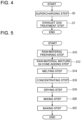
- FIG 4 is a schematic flowchart of an example of steps of an exhaust gas treatment method performed by the gas engine power generation system 50 in FIG 3 .
- the exhaust gas treatment method comprises a supercharging step S5 of rotating the exhaust turbine 76 of the turbocharger 58 with exhaust gas discharged from the gas engine 52 and compressing air supplied to the gas engine 52 by the compressor 67 of the turbocharger 58, and an exhaust gas treatment step S7 of causing exhaust gas to contact an exhaust gas treatment catalyst including a perovskite composite oxide containing at least Ag and Dy in the A site and at least Mn in the B site.
- the above described exhaust gas treatment method includes a step of causing exhaust gas to contact an exhaust gas treatment catalyst which includes a perovskite composite oxide containing at least Ag and Dy in the A site, and at least Mn in the B site, and thus has a high performance of oxidization removal of VOC such as formaldehyde.
- a perovskite composite oxide containing at least Ag and Dy in the A site and at least Mn in the B site has a higher VOC removing performance at a low temperature than a catalyst of platinum-supported alumina.
- a perovskite composite oxide containing at least Ag and Dy in the A site and at least Mn in the B site has an excellent low-temperature activation property.
- the temperature of exhaust gas may decrease more than typical art in the supercharging step S5.
- the perovskite composite oxide has a composition expressed by a general expression Ag ⁇ Dy 1- ⁇ MnO 3 (0.01 ⁇ ⁇ ⁇ 0.20).
- the exhaust gas treatment catalyst includes a perovskite composite oxide having a composition expressed by a general expression Ag ⁇ Dy 1- ⁇ MnO 3 (0.01 ⁇ ⁇ ⁇ 0.20), and thus has a high performance of oxidizing VOC, formaldehyde in particular.
- the perovskite composite oxide has a composition expressed by a general expression Ag 0.12 Dy 0.88 MnO 3 .
- the exhaust gas treatment catalyst includes a perovskite composite oxide having a composition expressed by a general expression Ag 0.12 Dy 0.88 MnO 3 , and thus has a high performance of oxidizing VOC, formaldehyde in particular.
- FIG 5 is a schematic flowchart of an example of steps of a method of producing a perovskite composite oxide.
- the method of producing a perovskite composite oxide includes a raw-material preparing step S10, a raw-material mixture glycine adding step S12, a melting step S14, a concentrating step S16, a drying step S18, a mixing step S20, and a baking step S22.
- raw materials are prepared. Specifically, a salt of metal containing metal atoms to constitute the A site, and a salt of metal containing metal atoms to constitute the B site are prepared.
- the salt of metal is nitrate or oxalate, for instance, and may be in form of solution.
- the prepared raw materials are mixed. Specifically, a plurality of salts of metal are mixed at a predetermined ratio so that the proportion of the number of metal atoms in the plurality of salts of metal corresponds to the composition of the perovskite composite oxide to be obtained.
- glycine adding step S12 glycine is added while the prepared raw materials are being mixed. For instance, glycine of 16 mol is added per 1 mol of the perovskite composite oxide to be obtained.
- an appropriate amount of solvent is added to the mixture of raw materials and glycine to dissolve the mixture.
- the solvent is pure water, for instance.
- the mixture obtained in the melting step S14 is stirred while heated, and thereby concentrated.
- the concentrate obtained in the concentrating step S16 is dried and solidified at a temperature of 100°C to 230°C.
- the solid matter obtained in the drying step S18 is fractured and mixed.
- the particulate matter obtained in the mixing step S20 is baked for approximately four hours at a temperature of not less than 500°C and not more than 900°C to obtain a perovskite composite oxide.
- an exhaust gas treatment catalyst including a perovskite composite oxide having a composition expressed by a general expression Ag 0.12 Dy 0.88 MnO 3 .
- a silver nitrate solution, a dysprosium nitrate solution, and a manganese nitrate solution are used as raw materials.
- the powder of exhaust gas treatment catalyst of each of embodiment 1 and comparative example 1 is formed into a 1g pellet-shaped oxidation catalyst including catalyst particles of 0.5mm to 1mm. Further, test gas having the following components is prepared.
- the test gas is flowed through each oxidation catalyst at a flow rate of approximately 4500Ncc/min while changing the temperature, and the HCHO concentration of test gas after passing through the oxidation catalyst device is measured. Then, from the change in the HCHO concentration before and after passing through the oxidation catalyst device, the HCHO removal rate is calculated.
- FIG 6 shows a relationship between the temperature of test gas after passing through the oxidation catalyst device and the HCHO removal rate ( ⁇ HCHO) in the temperature range of 200°C to 500°C. The temperature increasing speed is 20°C/min.
- the HCHO removal rate of the embodiment 1 is higher than the comparative example 1 in the temperature range of approximately 200°C to 500°C. Accordingly, the exhaust gas treatment catalyst including a perovskite composite oxide having a composition expressed by a general expression Ag 0.12 Dy 0.88 MnO 3 has a higher HCHO oxidation removal performance than Pt-supported alumina.
- the costs of the oxidation catalyst in the embodiment 1 is approximately 61% of the cost of the oxidation catalyst of the comparative embodiment 1, and thus it is possible to cut 39% of the raw material costs of the catalyst.
- the costs of the oxidation catalyst of the embodiment 1 is approximately 35% of the cost of the oxidation catalyst of the comparative example 1, and thus it is possible to cut 65% of the raw material costs of the catalyst.
- the test gas is flowed through each oxidation catalyst at a flow rate of approximately 4500Ncc/min while changing the temperature, and the NO 2 concentration of test gas after passing through the oxidation catalyst is measured. From NO (nitrogen oxide) before and after passing through the oxidation catalyst device, the generation rate (conversion rate) of NO 2 is calculated.
- FIG 7 shows a relationship between the temperature of test gas after passing through the oxidation catalyst device and the NO 2 generation rate ( ⁇ NO 2 ).
- the NO 2 generation rate of the embodiment 1 is higher than the comparative example 1 at a temperature higher than approximately 300°C.
- the oxidation catalyst including a perovskite composite oxide having a composition expressed by a general expression Ag 0.12 Dy 0.88 MnO 3 has a higher NO 2 generation rate or a higher NOx oxidation performance than Pt-supported alumina.
- the denitration devices 29, 86 include an SCR catalyst which reduces NO and NO 2 in the presence of ammonia. The higher the concentration of NO 2 , the higher the reduction efficiency.
- the oxidation catalyst device 88 may be disposed upstream of the denitration device 86 in the exhaust gas treatment device 60.
Landscapes
- Chemical & Material Sciences (AREA)
- Engineering & Computer Science (AREA)
- Chemical Kinetics & Catalysis (AREA)
- Environmental & Geological Engineering (AREA)
- Materials Engineering (AREA)
- Organic Chemistry (AREA)
- Combustion & Propulsion (AREA)
- General Engineering & Computer Science (AREA)
- Mechanical Engineering (AREA)
- Health & Medical Sciences (AREA)
- Analytical Chemistry (AREA)
- Oil, Petroleum & Natural Gas (AREA)
- General Chemical & Material Sciences (AREA)
- Biomedical Technology (AREA)
- Toxicology (AREA)
- Physics & Mathematics (AREA)
- Thermal Sciences (AREA)
- Exhaust Gas Treatment By Means Of Catalyst (AREA)
- Catalysts (AREA)
- Incineration Of Waste (AREA)
Applications Claiming Priority (3)
| Application Number | Priority Date | Filing Date | Title |
|---|---|---|---|
| JP2014251062A JP2016112483A (ja) | 2014-12-11 | 2014-12-11 | 排ガス処理装置、ガスタービンコンバインドサイクル発電システム、ガスエンジン発電システム及び排ガス処理方法 |
| PCT/JP2015/076322 WO2016092931A1 (ja) | 2014-12-11 | 2015-09-16 | 排ガス処理装置、ガスタービンコンバインドサイクル発電システム、ガスエンジン発電システム及び排ガス処理方法 |
| EP15867542.1A EP3231499B1 (en) | 2014-12-11 | 2015-09-16 | Gas engine power generation system and exhaust gas treatment method |
Related Parent Applications (2)
| Application Number | Title | Priority Date | Filing Date |
|---|---|---|---|
| EP15867542.1A Division-Into EP3231499B1 (en) | 2014-12-11 | 2015-09-16 | Gas engine power generation system and exhaust gas treatment method |
| EP15867542.1A Division EP3231499B1 (en) | 2014-12-11 | 2015-09-16 | Gas engine power generation system and exhaust gas treatment method |
Publications (2)
| Publication Number | Publication Date |
|---|---|
| EP3865203A1 EP3865203A1 (en) | 2021-08-18 |
| EP3865203B1 true EP3865203B1 (en) | 2023-08-16 |
Family
ID=56107126
Family Applications (2)
| Application Number | Title | Priority Date | Filing Date |
|---|---|---|---|
| EP21159439.5A Active EP3865203B1 (en) | 2014-12-11 | 2015-09-16 | Gas turbine combined cycle power generation system, and exhaust gas treatment method |
| EP15867542.1A Active EP3231499B1 (en) | 2014-12-11 | 2015-09-16 | Gas engine power generation system and exhaust gas treatment method |
Family Applications After (1)
| Application Number | Title | Priority Date | Filing Date |
|---|---|---|---|
| EP15867542.1A Active EP3231499B1 (en) | 2014-12-11 | 2015-09-16 | Gas engine power generation system and exhaust gas treatment method |
Country Status (5)
| Country | Link |
|---|---|
| US (1) | US20170312689A1 (enExample) |
| EP (2) | EP3865203B1 (enExample) |
| JP (1) | JP2016112483A (enExample) |
| CN (1) | CN106999846B (enExample) |
| WO (1) | WO2016092931A1 (enExample) |
Families Citing this family (3)
| Publication number | Priority date | Publication date | Assignee | Title |
|---|---|---|---|---|
| CN110026185A (zh) * | 2018-11-23 | 2019-07-19 | 江苏中创清源科技有限公司 | 一种改性钙钛矿型催化剂及其制备方法 |
| CN112728566A (zh) * | 2020-11-29 | 2021-04-30 | 中船海洋动力部件有限公司 | 一种高效节能催化燃烧一体化装置 |
| JP2023161201A (ja) * | 2022-04-25 | 2023-11-07 | 三菱重工業株式会社 | 排ガス処理装置、燃焼設備及び排ガス処理方法 |
Family Cites Families (12)
| Publication number | Priority date | Publication date | Assignee | Title |
|---|---|---|---|---|
| JPH06182201A (ja) * | 1984-07-31 | 1994-07-05 | Hitachi Ltd | 高温で安定な触媒及びその調製法ならびにその触媒を用いて化学反応を実施する方法 |
| EP0968763A4 (en) * | 1997-10-14 | 2002-06-12 | Isuzu Ceramics Res Inst | EXHAUST GAS PURIFICATION CATALYST |
| JP2004041868A (ja) * | 2002-07-09 | 2004-02-12 | Daihatsu Motor Co Ltd | 排ガス浄化用触媒 |
| JP4311918B2 (ja) * | 2002-07-09 | 2009-08-12 | ダイハツ工業株式会社 | ペロブスカイト型複合酸化物の製造方法 |
| JP4689574B2 (ja) | 2006-10-20 | 2011-05-25 | 本田技研工業株式会社 | 排ガス浄化用酸化触媒 |
| JP5095538B2 (ja) | 2008-07-15 | 2012-12-12 | 本田技研工業株式会社 | 排ガス浄化用酸化触媒装置 |
| US8741239B2 (en) * | 2009-02-25 | 2014-06-03 | General Electric Company | Method and apparatus for operation of CO/VOC oxidation catalyst to reduce NO2 formation for gas turbine |
| JP2012047096A (ja) * | 2010-08-26 | 2012-03-08 | Mitsubishi Heavy Ind Ltd | 舶用脱硝システムおよびこれを備えた船舶ならびに舶用脱硝システムの制御方法 |
| US20120102951A1 (en) * | 2010-10-29 | 2012-05-03 | Gilbert Otto Kraemer | Apparatus for reducing emissions and method of assembly |
| US20140090374A1 (en) * | 2012-10-03 | 2014-04-03 | Caterpollar Inc. | Exhaust aftertreatment system and method |
| JP6151533B2 (ja) * | 2013-02-22 | 2017-06-21 | 三菱重工業株式会社 | 排熱回収ボイラ向け脱硝パックの搬入システム及びその方法、並びに排熱回収ボイラ |
| JP2015136684A (ja) * | 2014-01-24 | 2015-07-30 | 三菱重工業株式会社 | 排ガス処理用触媒、該触媒を用いた排ガス処理システム及び排ガス処理方法 |
-
2014
- 2014-12-11 JP JP2014251062A patent/JP2016112483A/ja active Pending
-
2015
- 2015-09-16 EP EP21159439.5A patent/EP3865203B1/en active Active
- 2015-09-16 US US15/533,883 patent/US20170312689A1/en not_active Abandoned
- 2015-09-16 WO PCT/JP2015/076322 patent/WO2016092931A1/ja not_active Ceased
- 2015-09-16 CN CN201580066574.1A patent/CN106999846B/zh not_active Expired - Fee Related
- 2015-09-16 EP EP15867542.1A patent/EP3231499B1/en active Active
Also Published As
| Publication number | Publication date |
|---|---|
| CN106999846B (zh) | 2020-03-20 |
| EP3231499A4 (en) | 2018-06-27 |
| EP3231499A1 (en) | 2017-10-18 |
| EP3231499B1 (en) | 2021-04-14 |
| CN106999846A (zh) | 2017-08-01 |
| JP2016112483A (ja) | 2016-06-23 |
| WO2016092931A1 (ja) | 2016-06-16 |
| EP3865203A1 (en) | 2021-08-18 |
| US20170312689A1 (en) | 2017-11-02 |
Similar Documents
| Publication | Publication Date | Title |
|---|---|---|
| Shin et al. | NOx abatement and N2O formation over urea-SCR systems with zeolite supported Fe and Cu catalysts in a nonroad diesel engine | |
| CN104379239B (zh) | 用于处理摩托车排气的贱金属催化剂组合物和方法 | |
| CN103702744B (zh) | 使用基于锆、铈和铌的组合物作为催化剂来处理含氮氧化物(NOx)的气体的方法 | |
| JP5934390B2 (ja) | 硫黄含有ガスストリーム中のΝOx排出物を制御するための選択触媒還元システム及びプロセス | |
| JP2023512906A (ja) | 火力発電所の排ガス処理方法 | |
| KR20110010118A (ko) | 수소를 이용한 NOx방출을 조절하는 촉매 방법 | |
| EP3865203B1 (en) | Gas turbine combined cycle power generation system, and exhaust gas treatment method | |
| CN108745364A (zh) | 一种用于催化氧化no的钙钛矿催化剂的制备方法 | |
| CN101879452A (zh) | 一种锰基低温脱硝催化剂及其制备方法 | |
| WO2017049804A1 (zh) | 低温催化去除环境污染物的催化剂及其制备方法 | |
| CN108722431A (zh) | 一种a位掺杂型双钙钛矿催化剂及其制备方法与应用 | |
| Zhou et al. | Experimental investigation on the characteristics of ammonia storage for heavy-duty diesel engine SCR catalyst | |
| US10876449B2 (en) | Internal combustion engine and method for operating same | |
| CN103736497A (zh) | 高效处理柴油机尾气中氮氧化物的钒基scr催化剂及其制备方法 | |
| CN115245820A (zh) | 一种尖晶石催化剂、其制备方法与应用 | |
| CN105396614A (zh) | 氨选择性催化还原去除氮氧化物的催化剂及制备和应用 | |
| CN100493697C (zh) | 一种球形铈锆基复合氧化物及其制备方法 | |
| JP2015136684A (ja) | 排ガス処理用触媒、該触媒を用いた排ガス処理システム及び排ガス処理方法 | |
| JP6339729B2 (ja) | 排ガス処理装置及び排ガス処理用触媒の製造方法 | |
| JP5875562B2 (ja) | 排ガス処理装置及び排ガス処理方法 | |
| CN112452321A (zh) | 一种低温催化净化氮氧化物催化剂及其制备方法 | |
| JP6182036B2 (ja) | 排ガス処理用触媒及び排ガス処理装置、並びに排ガス処理用触媒の製造方法 | |
| Sultana et al. | Development and validation of rare earth modified Fe-BEA SCR catalyst for mitigation of NOx from NH3 gas turbine | |
| CN110227538A (zh) | 同时去除NOx和PM的高活性DPF涂层的制备方法 | |
| JP2018167201A (ja) | ガスタービン排ガス処理用酸化触媒、並びにそれを用いた装置及び方法 |
Legal Events
| Date | Code | Title | Description |
|---|---|---|---|
| PUAI | Public reference made under article 153(3) epc to a published international application that has entered the european phase |
Free format text: ORIGINAL CODE: 0009012 |
|
| STAA | Information on the status of an ep patent application or granted ep patent |
Free format text: STATUS: REQUEST FOR EXAMINATION WAS MADE |
|
| 17P | Request for examination filed |
Effective date: 20210225 |
|
| AC | Divisional application: reference to earlier application |
Ref document number: 3231499 Country of ref document: EP Kind code of ref document: P |
|
| AK | Designated contracting states |
Kind code of ref document: A1 Designated state(s): AL AT BE BG CH CY CZ DE DK EE ES FI FR GB GR HR HU IE IS IT LI LT LU LV MC MK MT NL NO PL PT RO RS SE SI SK SM TR |
|
| GRAP | Despatch of communication of intention to grant a patent |
Free format text: ORIGINAL CODE: EPIDOSNIGR1 |
|
| STAA | Information on the status of an ep patent application or granted ep patent |
Free format text: STATUS: GRANT OF PATENT IS INTENDED |
|
| INTG | Intention to grant announced |
Effective date: 20230303 |
|
| GRAS | Grant fee paid |
Free format text: ORIGINAL CODE: EPIDOSNIGR3 |
|
| GRAA | (expected) grant |
Free format text: ORIGINAL CODE: 0009210 |
|
| STAA | Information on the status of an ep patent application or granted ep patent |
Free format text: STATUS: THE PATENT HAS BEEN GRANTED |
|
| AC | Divisional application: reference to earlier application |
Ref document number: 3231499 Country of ref document: EP Kind code of ref document: P |
|
| AK | Designated contracting states |
Kind code of ref document: B1 Designated state(s): AL AT BE BG CH CY CZ DE DK EE ES FI FR GB GR HR HU IE IS IT LI LT LU LV MC MK MT NL NO PL PT RO RS SE SI SK SM TR |
|
| REG | Reference to a national code |
Ref country code: CH Ref legal event code: EP Ref country code: DE Ref legal event code: R096 Ref document number: 602015085230 Country of ref document: DE |
|
| REG | Reference to a national code |
Ref country code: IE Ref legal event code: FG4D |
|
| REG | Reference to a national code |
Ref country code: LT Ref legal event code: MG9D |
|
| REG | Reference to a national code |
Ref country code: NL Ref legal event code: MP Effective date: 20230816 |
|
| REG | Reference to a national code |
Ref country code: AT Ref legal event code: MK05 Ref document number: 1599482 Country of ref document: AT Kind code of ref document: T Effective date: 20230816 |
|
| PG25 | Lapsed in a contracting state [announced via postgrant information from national office to epo] |
Ref country code: GR Free format text: LAPSE BECAUSE OF FAILURE TO SUBMIT A TRANSLATION OF THE DESCRIPTION OR TO PAY THE FEE WITHIN THE PRESCRIBED TIME-LIMIT Effective date: 20231117 |
|
| PG25 | Lapsed in a contracting state [announced via postgrant information from national office to epo] |
Ref country code: IS Free format text: LAPSE BECAUSE OF FAILURE TO SUBMIT A TRANSLATION OF THE DESCRIPTION OR TO PAY THE FEE WITHIN THE PRESCRIBED TIME-LIMIT Effective date: 20231216 |
|
| PG25 | Lapsed in a contracting state [announced via postgrant information from national office to epo] |
Ref country code: SE Free format text: LAPSE BECAUSE OF FAILURE TO SUBMIT A TRANSLATION OF THE DESCRIPTION OR TO PAY THE FEE WITHIN THE PRESCRIBED TIME-LIMIT Effective date: 20230816 Ref country code: RS Free format text: LAPSE BECAUSE OF FAILURE TO SUBMIT A TRANSLATION OF THE DESCRIPTION OR TO PAY THE FEE WITHIN THE PRESCRIBED TIME-LIMIT Effective date: 20230816 Ref country code: PT Free format text: LAPSE BECAUSE OF FAILURE TO SUBMIT A TRANSLATION OF THE DESCRIPTION OR TO PAY THE FEE WITHIN THE PRESCRIBED TIME-LIMIT Effective date: 20231218 Ref country code: NO Free format text: LAPSE BECAUSE OF FAILURE TO SUBMIT A TRANSLATION OF THE DESCRIPTION OR TO PAY THE FEE WITHIN THE PRESCRIBED TIME-LIMIT Effective date: 20231116 Ref country code: NL Free format text: LAPSE BECAUSE OF FAILURE TO SUBMIT A TRANSLATION OF THE DESCRIPTION OR TO PAY THE FEE WITHIN THE PRESCRIBED TIME-LIMIT Effective date: 20230816 Ref country code: LV Free format text: LAPSE BECAUSE OF FAILURE TO SUBMIT A TRANSLATION OF THE DESCRIPTION OR TO PAY THE FEE WITHIN THE PRESCRIBED TIME-LIMIT Effective date: 20230816 Ref country code: LT Free format text: LAPSE BECAUSE OF FAILURE TO SUBMIT A TRANSLATION OF THE DESCRIPTION OR TO PAY THE FEE WITHIN THE PRESCRIBED TIME-LIMIT Effective date: 20230816 Ref country code: IS Free format text: LAPSE BECAUSE OF FAILURE TO SUBMIT A TRANSLATION OF THE DESCRIPTION OR TO PAY THE FEE WITHIN THE PRESCRIBED TIME-LIMIT Effective date: 20231216 Ref country code: HR Free format text: LAPSE BECAUSE OF FAILURE TO SUBMIT A TRANSLATION OF THE DESCRIPTION OR TO PAY THE FEE WITHIN THE PRESCRIBED TIME-LIMIT Effective date: 20230816 Ref country code: GR Free format text: LAPSE BECAUSE OF FAILURE TO SUBMIT A TRANSLATION OF THE DESCRIPTION OR TO PAY THE FEE WITHIN THE PRESCRIBED TIME-LIMIT Effective date: 20231117 Ref country code: FI Free format text: LAPSE BECAUSE OF FAILURE TO SUBMIT A TRANSLATION OF THE DESCRIPTION OR TO PAY THE FEE WITHIN THE PRESCRIBED TIME-LIMIT Effective date: 20230816 Ref country code: AT Free format text: LAPSE BECAUSE OF FAILURE TO SUBMIT A TRANSLATION OF THE DESCRIPTION OR TO PAY THE FEE WITHIN THE PRESCRIBED TIME-LIMIT Effective date: 20230816 |
|
| PG25 | Lapsed in a contracting state [announced via postgrant information from national office to epo] |
Ref country code: PL Free format text: LAPSE BECAUSE OF FAILURE TO SUBMIT A TRANSLATION OF THE DESCRIPTION OR TO PAY THE FEE WITHIN THE PRESCRIBED TIME-LIMIT Effective date: 20230816 |
|
| PG25 | Lapsed in a contracting state [announced via postgrant information from national office to epo] |
Ref country code: ES Free format text: LAPSE BECAUSE OF FAILURE TO SUBMIT A TRANSLATION OF THE DESCRIPTION OR TO PAY THE FEE WITHIN THE PRESCRIBED TIME-LIMIT Effective date: 20230816 |
|
| PG25 | Lapsed in a contracting state [announced via postgrant information from national office to epo] |
Ref country code: SM Free format text: LAPSE BECAUSE OF FAILURE TO SUBMIT A TRANSLATION OF THE DESCRIPTION OR TO PAY THE FEE WITHIN THE PRESCRIBED TIME-LIMIT Effective date: 20230816 Ref country code: RO Free format text: LAPSE BECAUSE OF FAILURE TO SUBMIT A TRANSLATION OF THE DESCRIPTION OR TO PAY THE FEE WITHIN THE PRESCRIBED TIME-LIMIT Effective date: 20230816 Ref country code: ES Free format text: LAPSE BECAUSE OF FAILURE TO SUBMIT A TRANSLATION OF THE DESCRIPTION OR TO PAY THE FEE WITHIN THE PRESCRIBED TIME-LIMIT Effective date: 20230816 Ref country code: EE Free format text: LAPSE BECAUSE OF FAILURE TO SUBMIT A TRANSLATION OF THE DESCRIPTION OR TO PAY THE FEE WITHIN THE PRESCRIBED TIME-LIMIT Effective date: 20230816 Ref country code: DK Free format text: LAPSE BECAUSE OF FAILURE TO SUBMIT A TRANSLATION OF THE DESCRIPTION OR TO PAY THE FEE WITHIN THE PRESCRIBED TIME-LIMIT Effective date: 20230816 Ref country code: CZ Free format text: LAPSE BECAUSE OF FAILURE TO SUBMIT A TRANSLATION OF THE DESCRIPTION OR TO PAY THE FEE WITHIN THE PRESCRIBED TIME-LIMIT Effective date: 20230816 Ref country code: SK Free format text: LAPSE BECAUSE OF FAILURE TO SUBMIT A TRANSLATION OF THE DESCRIPTION OR TO PAY THE FEE WITHIN THE PRESCRIBED TIME-LIMIT Effective date: 20230816 |
|
| REG | Reference to a national code |
Ref country code: CH Ref legal event code: PL |
|
| PG25 | Lapsed in a contracting state [announced via postgrant information from national office to epo] |
Ref country code: LU Free format text: LAPSE BECAUSE OF NON-PAYMENT OF DUE FEES Effective date: 20230916 |
|
| REG | Reference to a national code |
Ref country code: DE Ref legal event code: R097 Ref document number: 602015085230 Country of ref document: DE |
|
| REG | Reference to a national code |
Ref country code: BE Ref legal event code: MM Effective date: 20230930 |
|
| PG25 | Lapsed in a contracting state [announced via postgrant information from national office to epo] |
Ref country code: LU Free format text: LAPSE BECAUSE OF NON-PAYMENT OF DUE FEES Effective date: 20230916 Ref country code: MC Free format text: LAPSE BECAUSE OF FAILURE TO SUBMIT A TRANSLATION OF THE DESCRIPTION OR TO PAY THE FEE WITHIN THE PRESCRIBED TIME-LIMIT Effective date: 20230816 |
|
| PLBE | No opposition filed within time limit |
Free format text: ORIGINAL CODE: 0009261 |
|
| STAA | Information on the status of an ep patent application or granted ep patent |
Free format text: STATUS: NO OPPOSITION FILED WITHIN TIME LIMIT |
|
| REG | Reference to a national code |
Ref country code: IE Ref legal event code: MM4A |
|
| PG25 | Lapsed in a contracting state [announced via postgrant information from national office to epo] |
Ref country code: IE Free format text: LAPSE BECAUSE OF NON-PAYMENT OF DUE FEES Effective date: 20230916 |
|
| PG25 | Lapsed in a contracting state [announced via postgrant information from national office to epo] |
Ref country code: CH Free format text: LAPSE BECAUSE OF NON-PAYMENT OF DUE FEES Effective date: 20230930 |
|
| 26N | No opposition filed |
Effective date: 20240517 |
|
| GBPC | Gb: european patent ceased through non-payment of renewal fee |
Effective date: 20231116 |
|
| PG25 | Lapsed in a contracting state [announced via postgrant information from national office to epo] |
Ref country code: IT Free format text: LAPSE BECAUSE OF FAILURE TO SUBMIT A TRANSLATION OF THE DESCRIPTION OR TO PAY THE FEE WITHIN THE PRESCRIBED TIME-LIMIT Effective date: 20230816 Ref country code: IE Free format text: LAPSE BECAUSE OF NON-PAYMENT OF DUE FEES Effective date: 20230916 Ref country code: FR Free format text: LAPSE BECAUSE OF NON-PAYMENT OF DUE FEES Effective date: 20231016 Ref country code: CH Free format text: LAPSE BECAUSE OF NON-PAYMENT OF DUE FEES Effective date: 20230930 Ref country code: SI Free format text: LAPSE BECAUSE OF FAILURE TO SUBMIT A TRANSLATION OF THE DESCRIPTION OR TO PAY THE FEE WITHIN THE PRESCRIBED TIME-LIMIT Effective date: 20230816 |
|
| PG25 | Lapsed in a contracting state [announced via postgrant information from national office to epo] |
Ref country code: BE Free format text: LAPSE BECAUSE OF NON-PAYMENT OF DUE FEES Effective date: 20230930 |
|
| PG25 | Lapsed in a contracting state [announced via postgrant information from national office to epo] |
Ref country code: GB Free format text: LAPSE BECAUSE OF NON-PAYMENT OF DUE FEES Effective date: 20231116 |
|
| PG25 | Lapsed in a contracting state [announced via postgrant information from national office to epo] |
Ref country code: GB Free format text: LAPSE BECAUSE OF NON-PAYMENT OF DUE FEES Effective date: 20231116 |
|
| PG25 | Lapsed in a contracting state [announced via postgrant information from national office to epo] |
Ref country code: BG Free format text: LAPSE BECAUSE OF FAILURE TO SUBMIT A TRANSLATION OF THE DESCRIPTION OR TO PAY THE FEE WITHIN THE PRESCRIBED TIME-LIMIT Effective date: 20230816 |
|
| PG25 | Lapsed in a contracting state [announced via postgrant information from national office to epo] |
Ref country code: BG Free format text: LAPSE BECAUSE OF FAILURE TO SUBMIT A TRANSLATION OF THE DESCRIPTION OR TO PAY THE FEE WITHIN THE PRESCRIBED TIME-LIMIT Effective date: 20230816 |
|
| PG25 | Lapsed in a contracting state [announced via postgrant information from national office to epo] |
Ref country code: CY Free format text: LAPSE BECAUSE OF FAILURE TO SUBMIT A TRANSLATION OF THE DESCRIPTION OR TO PAY THE FEE WITHIN THE PRESCRIBED TIME-LIMIT; INVALID AB INITIO Effective date: 20150916 |
|
| PG25 | Lapsed in a contracting state [announced via postgrant information from national office to epo] |
Ref country code: HU Free format text: LAPSE BECAUSE OF FAILURE TO SUBMIT A TRANSLATION OF THE DESCRIPTION OR TO PAY THE FEE WITHIN THE PRESCRIBED TIME-LIMIT; INVALID AB INITIO Effective date: 20150916 |
|
| PGFP | Annual fee paid to national office [announced via postgrant information from national office to epo] |
Ref country code: DE Payment date: 20250730 Year of fee payment: 11 |