WO2016092931A1 - 排ガス処理装置、ガスタービンコンバインドサイクル発電システム、ガスエンジン発電システム及び排ガス処理方法 - Google Patents
排ガス処理装置、ガスタービンコンバインドサイクル発電システム、ガスエンジン発電システム及び排ガス処理方法 Download PDFInfo
- Publication number
- WO2016092931A1 WO2016092931A1 PCT/JP2015/076322 JP2015076322W WO2016092931A1 WO 2016092931 A1 WO2016092931 A1 WO 2016092931A1 JP 2015076322 W JP2015076322 W JP 2015076322W WO 2016092931 A1 WO2016092931 A1 WO 2016092931A1
- Authority
- WO
- WIPO (PCT)
- Prior art keywords
- exhaust gas
- gas
- site
- turbine
- gas treatment
- Prior art date
- Legal status (The legal status is an assumption and is not a legal conclusion. Google has not performed a legal analysis and makes no representation as to the accuracy of the status listed.)
- Ceased
Links
Images


Classifications
-
- B—PERFORMING OPERATIONS; TRANSPORTING
- B01—PHYSICAL OR CHEMICAL PROCESSES OR APPARATUS IN GENERAL
- B01D—SEPARATION
- B01D53/00—Separation of gases or vapours; Recovering vapours of volatile solvents from gases; Chemical or biological purification of waste gases, e.g. engine exhaust gases, smoke, fumes, flue gases, aerosols
- B01D53/34—Chemical or biological purification of waste gases
- B01D53/92—Chemical or biological purification of waste gases of engine exhaust gases
- B01D53/94—Chemical or biological purification of waste gases of engine exhaust gases by catalytic processes
- B01D53/944—Simultaneously removing carbon monoxide, hydrocarbons or carbon making use of oxidation catalysts
-
- B—PERFORMING OPERATIONS; TRANSPORTING
- B01—PHYSICAL OR CHEMICAL PROCESSES OR APPARATUS IN GENERAL
- B01D—SEPARATION
- B01D53/00—Separation of gases or vapours; Recovering vapours of volatile solvents from gases; Chemical or biological purification of waste gases, e.g. engine exhaust gases, smoke, fumes, flue gases, aerosols
- B01D53/34—Chemical or biological purification of waste gases
- B01D53/74—General processes for purification of waste gases; Apparatus or devices specially adapted therefor
- B01D53/86—Catalytic processes
- B01D53/8668—Removing organic compounds not provided for in B01D53/8603 - B01D53/8665
-
- B—PERFORMING OPERATIONS; TRANSPORTING
- B01—PHYSICAL OR CHEMICAL PROCESSES OR APPARATUS IN GENERAL
- B01D—SEPARATION
- B01D53/00—Separation of gases or vapours; Recovering vapours of volatile solvents from gases; Chemical or biological purification of waste gases, e.g. engine exhaust gases, smoke, fumes, flue gases, aerosols
- B01D53/34—Chemical or biological purification of waste gases
- B01D53/74—General processes for purification of waste gases; Apparatus or devices specially adapted therefor
- B01D53/86—Catalytic processes
-
- B—PERFORMING OPERATIONS; TRANSPORTING
- B01—PHYSICAL OR CHEMICAL PROCESSES OR APPARATUS IN GENERAL
- B01J—CHEMICAL OR PHYSICAL PROCESSES, e.g. CATALYSIS OR COLLOID CHEMISTRY; THEIR RELEVANT APPARATUS
- B01J23/00—Catalysts comprising metals or metal oxides or hydroxides, not provided for in group B01J21/00
- B01J23/002—Mixed oxides other than spinels, e.g. perovskite
-
- B—PERFORMING OPERATIONS; TRANSPORTING
- B01—PHYSICAL OR CHEMICAL PROCESSES OR APPARATUS IN GENERAL
- B01J—CHEMICAL OR PHYSICAL PROCESSES, e.g. CATALYSIS OR COLLOID CHEMISTRY; THEIR RELEVANT APPARATUS
- B01J23/00—Catalysts comprising metals or metal oxides or hydroxides, not provided for in group B01J21/00
- B01J23/38—Catalysts comprising metals or metal oxides or hydroxides, not provided for in group B01J21/00 of noble metals
- B01J23/54—Catalysts comprising metals or metal oxides or hydroxides, not provided for in group B01J21/00 of noble metals combined with metals, oxides or hydroxides provided for in groups B01J23/02 - B01J23/36
- B01J23/66—Silver or gold
- B01J23/68—Silver or gold with arsenic, antimony, bismuth, vanadium, niobium, tantalum, polonium, chromium, molybdenum, tungsten, manganese, technetium or rhenium
- B01J23/688—Silver or gold with arsenic, antimony, bismuth, vanadium, niobium, tantalum, polonium, chromium, molybdenum, tungsten, manganese, technetium or rhenium with manganese, technetium or rhenium
-
- B—PERFORMING OPERATIONS; TRANSPORTING
- B01—PHYSICAL OR CHEMICAL PROCESSES OR APPARATUS IN GENERAL
- B01J—CHEMICAL OR PHYSICAL PROCESSES, e.g. CATALYSIS OR COLLOID CHEMISTRY; THEIR RELEVANT APPARATUS
- B01J37/00—Processes, in general, for preparing catalysts; Processes, in general, for activation of catalysts
- B01J37/04—Mixing
-
- B—PERFORMING OPERATIONS; TRANSPORTING
- B01—PHYSICAL OR CHEMICAL PROCESSES OR APPARATUS IN GENERAL
- B01J—CHEMICAL OR PHYSICAL PROCESSES, e.g. CATALYSIS OR COLLOID CHEMISTRY; THEIR RELEVANT APPARATUS
- B01J37/00—Processes, in general, for preparing catalysts; Processes, in general, for activation of catalysts
- B01J37/08—Heat treatment
-
- F—MECHANICAL ENGINEERING; LIGHTING; HEATING; WEAPONS; BLASTING
- F01—MACHINES OR ENGINES IN GENERAL; ENGINE PLANTS IN GENERAL; STEAM ENGINES
- F01K—STEAM ENGINE PLANTS; STEAM ACCUMULATORS; ENGINE PLANTS NOT OTHERWISE PROVIDED FOR; ENGINES USING SPECIAL WORKING FLUIDS OR CYCLES
- F01K23/00—Plants characterised by more than one engine delivering power external to the plant, the engines being driven by different fluids
- F01K23/02—Plants characterised by more than one engine delivering power external to the plant, the engines being driven by different fluids the engine cycles being thermally coupled
- F01K23/06—Plants characterised by more than one engine delivering power external to the plant, the engines being driven by different fluids the engine cycles being thermally coupled combustion heat from one cycle heating the fluid in another cycle
- F01K23/10—Plants characterised by more than one engine delivering power external to the plant, the engines being driven by different fluids the engine cycles being thermally coupled combustion heat from one cycle heating the fluid in another cycle with exhaust fluid of one cycle heating the fluid in another cycle
-
- F—MECHANICAL ENGINEERING; LIGHTING; HEATING; WEAPONS; BLASTING
- F01—MACHINES OR ENGINES IN GENERAL; ENGINE PLANTS IN GENERAL; STEAM ENGINES
- F01N—GAS-FLOW SILENCERS OR EXHAUST APPARATUS FOR MACHINES OR ENGINES IN GENERAL; GAS-FLOW SILENCERS OR EXHAUST APPARATUS FOR INTERNAL-COMBUSTION ENGINES
- F01N3/00—Exhaust or silencing apparatus having means for purifying, rendering innocuous, or otherwise treating exhaust
- F01N3/08—Exhaust or silencing apparatus having means for purifying, rendering innocuous, or otherwise treating exhaust for rendering innocuous
- F01N3/10—Exhaust or silencing apparatus having means for purifying, rendering innocuous, or otherwise treating exhaust for rendering innocuous by thermal or catalytic conversion of noxious components of exhaust
- F01N3/18—Exhaust or silencing apparatus having means for purifying, rendering innocuous, or otherwise treating exhaust for rendering innocuous by thermal or catalytic conversion of noxious components of exhaust characterised by methods of operation; Control
- F01N3/20—Exhaust or silencing apparatus having means for purifying, rendering innocuous, or otherwise treating exhaust for rendering innocuous by thermal or catalytic conversion of noxious components of exhaust characterised by methods of operation; Control specially adapted for catalytic conversion
-
- F—MECHANICAL ENGINEERING; LIGHTING; HEATING; WEAPONS; BLASTING
- F23—COMBUSTION APPARATUS; COMBUSTION PROCESSES
- F23G—CREMATION FURNACES; CONSUMING WASTE PRODUCTS BY COMBUSTION
- F23G7/00—Incinerators or other apparatus for consuming industrial waste, e.g. chemicals
- F23G7/06—Incinerators or other apparatus for consuming industrial waste, e.g. chemicals of waste gases or noxious gases, e.g. exhaust gases
- F23G7/07—Incinerators or other apparatus for consuming industrial waste, e.g. chemicals of waste gases or noxious gases, e.g. exhaust gases in which combustion takes place in the presence of catalytic material
-
- F—MECHANICAL ENGINEERING; LIGHTING; HEATING; WEAPONS; BLASTING
- F23—COMBUSTION APPARATUS; COMBUSTION PROCESSES
- F23R—GENERATING COMBUSTION PRODUCTS OF HIGH PRESSURE OR HIGH VELOCITY, e.g. GAS-TURBINE COMBUSTION CHAMBERS
- F23R3/00—Continuous combustion chambers using liquid or gaseous fuel
- F23R3/40—Continuous combustion chambers using liquid or gaseous fuel characterised by the use of catalytic means
-
- B—PERFORMING OPERATIONS; TRANSPORTING
- B01—PHYSICAL OR CHEMICAL PROCESSES OR APPARATUS IN GENERAL
- B01D—SEPARATION
- B01D2255/00—Catalysts
- B01D2255/10—Noble metals or compounds thereof
- B01D2255/104—Silver
-
- B—PERFORMING OPERATIONS; TRANSPORTING
- B01—PHYSICAL OR CHEMICAL PROCESSES OR APPARATUS IN GENERAL
- B01D—SEPARATION
- B01D2255/00—Catalysts
- B01D2255/20—Metals or compounds thereof
- B01D2255/206—Rare earth metals
-
- B—PERFORMING OPERATIONS; TRANSPORTING
- B01—PHYSICAL OR CHEMICAL PROCESSES OR APPARATUS IN GENERAL
- B01D—SEPARATION
- B01D2255/00—Catalysts
- B01D2255/20—Metals or compounds thereof
- B01D2255/207—Transition metals
- B01D2255/2073—Manganese
-
- B—PERFORMING OPERATIONS; TRANSPORTING
- B01—PHYSICAL OR CHEMICAL PROCESSES OR APPARATUS IN GENERAL
- B01D—SEPARATION
- B01D2255/00—Catalysts
- B01D2255/40—Mixed oxides
- B01D2255/402—Perovskites
-
- B—PERFORMING OPERATIONS; TRANSPORTING
- B01—PHYSICAL OR CHEMICAL PROCESSES OR APPARATUS IN GENERAL
- B01D—SEPARATION
- B01D2257/00—Components to be removed
- B01D2257/70—Organic compounds not provided for in groups B01D2257/00 - B01D2257/602
- B01D2257/708—Volatile organic compounds V.O.C.'s
-
- B—PERFORMING OPERATIONS; TRANSPORTING
- B01—PHYSICAL OR CHEMICAL PROCESSES OR APPARATUS IN GENERAL
- B01D—SEPARATION
- B01D2258/00—Sources of waste gases
- B01D2258/02—Other waste gases
- B01D2258/0283—Flue gases
-
- Y—GENERAL TAGGING OF NEW TECHNOLOGICAL DEVELOPMENTS; GENERAL TAGGING OF CROSS-SECTIONAL TECHNOLOGIES SPANNING OVER SEVERAL SECTIONS OF THE IPC; TECHNICAL SUBJECTS COVERED BY FORMER USPC CROSS-REFERENCE ART COLLECTIONS [XRACs] AND DIGESTS
- Y02—TECHNOLOGIES OR APPLICATIONS FOR MITIGATION OR ADAPTATION AGAINST CLIMATE CHANGE
- Y02E—REDUCTION OF GREENHOUSE GAS [GHG] EMISSIONS, RELATED TO ENERGY GENERATION, TRANSMISSION OR DISTRIBUTION
- Y02E20/00—Combustion technologies with mitigation potential
- Y02E20/12—Heat utilisation in combustion or incineration of waste
-
- Y—GENERAL TAGGING OF NEW TECHNOLOGICAL DEVELOPMENTS; GENERAL TAGGING OF CROSS-SECTIONAL TECHNOLOGIES SPANNING OVER SEVERAL SECTIONS OF THE IPC; TECHNICAL SUBJECTS COVERED BY FORMER USPC CROSS-REFERENCE ART COLLECTIONS [XRACs] AND DIGESTS
- Y02—TECHNOLOGIES OR APPLICATIONS FOR MITIGATION OR ADAPTATION AGAINST CLIMATE CHANGE
- Y02E—REDUCTION OF GREENHOUSE GAS [GHG] EMISSIONS, RELATED TO ENERGY GENERATION, TRANSMISSION OR DISTRIBUTION
- Y02E20/00—Combustion technologies with mitigation potential
- Y02E20/16—Combined cycle power plant [CCPP], or combined cycle gas turbine [CCGT]
Definitions
- the present disclosure relates to an exhaust gas processing device, a gas turbine combined cycle power generation system, a gas engine power generation system, and an exhaust gas processing method.
- Pt was supported on alumina as a catalyst for oxidizing and removing aldehydes, which are unburned products of fuel, mainly formaldehyde from the exhaust gas of gas turbines and gas engines. The thing is used.
- Patent Document 1 As an oxidation catalyst for oxidizing inclusions such as particulates and high-boiling hydrocarbons contained in exhaust gas of an internal combustion engine, Patent Document 1 has a general formula: Y 1-x Ag x MnO 3 (0.01 ⁇ Disclosed is an oxidation catalyst having a composition represented by x ⁇ 0.15).
- Patent Document 3 describes a composite metal oxide having a composition represented by the general formula: Y 0.95 Ag 0.05 MnO 3 Discloses a catalyst comprising a porous body of a mixture of zirconium oxide.
- An object of at least one embodiment of the present invention is to provide an exhaust gas processing device, a gas turbine combined cycle power generation system, a gas engine power generation system, and an exhaust gas processing method, which are excellent in VOC removal performance.
- the present inventors have repeatedly conducted various studies to develop a novel exhaust gas processing catalyst excellent in the oxidation performance of VOC, particularly formaldehyde, and show that Ag (silver) and Dy (dysprosium) are promising as elements of A site.
- the present invention has been conceived.
- An exhaust gas processing device is an exhaust gas processing device capable of processing the exhaust gas of a gas turbine or a gas engine,
- a catalyst for exhaust gas treatment is provided comprising a perovskite-type composite oxide containing at least Ag and Dy at A site and at least Mn at B site.
- the exhaust gas treatment apparatus of the above configuration (1) has an exhaust gas treatment catalyst comprising a perovskite type composite oxide containing at least Ag and Dy at A site and at least Mn at B site, therefore oxidation removal of VOC such as formaldehyde It is excellent in performance.
- a perovskite-type composite oxide containing at least Ag and Dy at A site and at least Mn at B site is superior to the catalyst having Pt supported on alumina at low temperature, and has the above-mentioned constitution
- VOCs can be efficiently removed. For this reason, VOC can be removed more efficiently than before when starting a gas turbine or gas engine.
- the exhaust gas processing system of the above configuration (1) is cheaper than the exhaust gas processing system mainly containing Pt as a noble metal.
- the exhaust gas processing device requires a large amount of precious metal, so the price merit of using Ag instead of Pt as the precious metal is extremely large.
- the exhaust gas processing device further includes a heat exchanger capable of recovering the heat of the exhaust gas of the gas turbine.
- the heat of the exhaust gas can be effectively used by recovering the heat of the exhaust gas by the heat exchanger.
- the temperature drop of the exhaust gas in the heat exchanger upstream of the exhaust gas treatment catalyst May be larger than conventional. Therefore, VOC can be efficiently removed from the low temperature exhaust gas while heating the steam with high efficiency using the high temperature exhaust gas.
- the perovskite complex oxide has a composition represented by a general formula: Ag ⁇ Dy 1 - ⁇ MnO 3 (0.01 ⁇ ⁇ ⁇ 0.20).
- the perovskite complex oxide has a composition represented by a general formula: Ag 0.12 Dy 0.88 MnO 3 .
- a gas turbine combined cycle power generation system With gas turbines, With a steam turbine, At least one generator capable of generating electricity by the power of the gas turbine and the steam turbine;
- An exhaust gas treatment device capable of treating the exhaust gas of the gas turbine;
- the exhaust gas treatment device is A catalyst for treating an exhaust gas comprising a perovskite complex oxide containing at least Ag and Dy at A site and at least Mn at B site, A heat exchanger disposed upstream of the exhaust gas treatment catalyst in the flow direction of the exhaust gas and capable of performing heat exchange between the exhaust gas and the steam supplied to the steam turbine; Have.
- the exhaust gas processing device removes VOCs from the exhaust gas, while providing the heat of the exhaust gas to the steam to generate power using the power of the steam turbine.
- the exhaust gas processing apparatus since the perovskite type composite oxide has excellent low temperature activity, VOCs can be efficiently removed even when the exhaust gas is at low temperature when the gas turbine combined cycle power generation system is started. Further, since the perovskite type complex oxide containing at least Ag and Dy at A site and at least Mn at B site has excellent low temperature activity, the heat exchanger upstream of the exhaust gas treatment catalyst in the flow direction of the exhaust gas The temperature reduction of the exhaust gas at the end may be greater than in the prior art.
- VOC can be efficiently removed from the low temperature exhaust gas while heating the steam with high efficiency using the high temperature exhaust gas.
- the gas turbine combined cycle power generation system of the above configuration (5) is environmentally friendly, has a high thermal efficiency and at the same time has a small amount of VOC contained in the exhaust gas discharged from the exhaust gas processing device.
- a gas engine power generation system With a gas engine, A generator capable of generating electricity by the power of the gas engine; A turbocharger capable of compressing air supplied to the gas engine; An exhaust gas treatment device capable of treating the exhaust gas of the gas engine;
- the exhaust gas treating apparatus has an exhaust gas treating catalyst comprising a perovskite type composite oxide containing at least Ag and Dy at A site and at least Mn at B site, An exhaust gas turbine of the turbocharger is disposed in an exhaust gas flow path extending between the gas engine and the exhaust gas treatment device.
- the exhaust gas treatment device removes VOCs in the exhaust gas.
- VOCs can be efficiently removed even when the exhaust gas is low temperature at the start of the gas engine power generation system.
- the perovskite type complex oxide containing at least Ag and Dy at A site and at least Mn at B site has excellent low temperature activity, the temperature decrease of the exhaust gas in the turbocharger may become larger than before . Therefore, it is possible to efficiently remove the VOC from the low temperature exhaust gas while efficiently converting the thermal energy of the high temperature exhaust gas into power by the turbocharger.
- the gas engine power generation system of the above configuration (6) has high thermal efficiency and at the same time is environmentally friendly, as the amount of VOC contained in the exhaust gas discharged from the exhaust gas processing device is small.
- An exhaust gas treatment step is provided in which an exhaust gas discharged from a gas turbine or gas engine is brought into contact with an exhaust gas treatment catalyst consisting of a perovskite type composite oxide containing at least Ag and Dy at A site and at least Mn at B site.
- the exhaust gas is brought into contact with an exhaust gas treatment catalyst comprising a perovskite type complex oxide containing at least Ag and Dy at A site and at least Mn at B site.
- an exhaust gas treatment catalyst comprising a perovskite type complex oxide containing at least Ag and Dy at A site and at least Mn at B site.
- a perovskite-type composite oxide containing at least Ag and Dy at A site and at least Mn at B site is superior to the catalyst having Pt supported on alumina at low temperature, and has the above-mentioned constitution
- the exhaust gas treatment method of (7) even if the exhaust gas has a low temperature, VOCs can be efficiently removed. For this reason, VOC can be removed more efficiently than before when starting a gas turbine or gas engine.
- the exhaust gas treatment method further includes, before the exhaust gas treatment step, a heat exchange step of bringing the exhaust gas discharged from the gas turbine into contact with a heat exchanger to recover the heat of the exhaust gas.
- the temperature of the exhaust gas in the heat exchange step is excellent because the perovskite type composite oxide containing at least Ag and Dy at A site and at least Mn at B site has excellent low temperature activity.
- the drop may be greater than conventional. Therefore, according to the exhaust gas treatment method of the above configuration (8), it is possible to efficiently remove the VOC from the low temperature exhaust gas while recovering heat from the high temperature exhaust gas with high efficiency.
- the exhaust gas treatment method prior to the exhaust gas treatment step, an exhaust gas turbine discharged from the gas engine is rotated to rotate an exhaust turbine of a turbocharger, and a compressor of the turbocharger compresses air supplied to the gas engine.
- the method further comprises the steps.
- the temperature of the exhaust gas in the supercharging step is excellent because the perovskite type composite oxide containing at least Ag and Dy at A site and at least Mn at B site has excellent low temperature activity.
- the drop may be greater than conventional. Therefore, according to the exhaust gas treatment method of the above configuration (9), it is possible to efficiently remove VOC from the low temperature exhaust gas while efficiently converting the thermal energy of the high temperature exhaust gas into power by the turbocharger. .
- an exhaust gas treatment device a gas turbine combined cycle power generation system, a gas engine power generation system, and an exhaust gas treatment method with excellent VOC removal performance are provided.
- expressions that indicate that things such as “identical”, “equal” and “homogeneous” are equal states not only represent strictly equal states, but also have tolerances or differences with which the same function can be obtained. It also represents the existing state.
- expressions representing shapes such as quadrilateral shapes and cylindrical shapes not only represent shapes such as rectangular shapes and cylindrical shapes in a geometrically strict sense, but also uneven portions and chamfers within the range where the same effect can be obtained. The shape including a part etc. shall also be expressed.
- the expressions “comprising”, “having”, “having”, “including” or “having” one component are not exclusive expressions excluding the presence of other components.
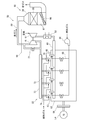
- FIG. 1 is a view schematically showing the configuration of a GTCC (gas turbine combined cycle) power generation system according to an embodiment of the present invention.
- the GTCC power generation system 1 is a combined power generation system, and includes a gas turbine 2, a steam turbine 3, an exhaust heat recovery boiler 5, and generators 7 and 9.
- the GTCC power generation system may be for business use or private use.
- the gas turbine 2 includes a compressor 11, a combustor 13, and a turbine 15.
- the compressor 11 compresses air using a part of the output of the turbine 15, and the compressed air is supplied to the combustor 13.
- the combustor 13 is supplied with compressed air and fuel to burn the fuel.
- the combustion gas generated by the fuel combustion is supplied to the turbine 15, and the turbine 15 outputs power using the combustion gas.
- the turbine 15 is connected to the generator 7, and the generator 7 generates power using a part of the power of the turbine 15.
- the combustion gas (hereinafter, also referred to as exhaust gas) that has been worked by the turbine 15 is supplied to the exhaust heat recovery boiler 5.
- the waste heat recovery boiler 5 is not only an exhaust gas treatment device for treating and purifying the exhaust gas, but also a heat exchange device for generating steam by using the heat (exhaust heat) of the exhaust gas.
- the exhaust heat recovery boiler 5 includes a housing 17 having an exhaust gas flow path 16 therein, an economizer 18, a header 19, an evaporator 21, a superheater 23, and a reheater 25.
- the economizer 18, the evaporator 21, the superheater 23, and the reheater 25 are disposed in the exhaust gas flow path 16, and are heat exchangers that perform heat exchange between the exhaust gas and water (steam).
- the water is heated by the economizer 18, the evaporator 21 and the superheater 23 to obtain superheated steam.
- the exhaust heat recovery boiler 5 has an oxidation catalyst device 27 and a denitration device 29 respectively disposed in the exhaust gas passage 16 in the housing 17 as an exhaust gas treatment device for purifying the exhaust gas flowing through the exhaust gas passage 16.
- the NOx removal device 29 is composed of an SCR catalyst (selective reduction catalyst), and has a function of removing NOx contained in the exhaust gas.
- the oxidation catalyst device 27 will be described later.
- the superheated steam generated by the exhaust heat recovery boiler 5 is supplied to the steam turbine 3.
- the steam turbine 3 is connected to a generator 9, the steam turbine 3 outputs power using steam, and the generator 9 generates power using power of the steam turbine 3.
- the steam turbine 3 has a high pressure turbine 31, an intermediate pressure turbine 33 and a low pressure turbine 35, and each of the high pressure turbine 31, the intermediate pressure turbine 33 and the low pressure turbine 35 outputs power using steam.
- Superheated steam is returned to the waste heat recovery boiler 5 once after working in the high pressure turbine 31 and supplied to the reheater 25.
- the reheater 25 heats the steam, and the heated steam is supplied to the medium pressure turbine 33 of the steam turbine 3.
- a condenser 37 is connected to the low pressure turbine 35, and the steam discharged from the low pressure turbine 35 of the steam turbine 3 is condensed by the condenser 37 and becomes water.
- the condenser 37 is connected to the exhaust heat recovery boiler 5 via a condensate pump 39, and the water obtained by the condenser 37 is supplied to the economizer 18 of the exhaust heat recovery boiler 5 by the condensate pump 39. Ru.
- the oxidation catalyst device 27 of the above-described exhaust heat recovery boiler is disposed, for example, in the portion of the exhaust gas flow path 16 extending between the reheater 25 and the superheater 23.
- the oxidation catalyst device 27 has a carrier and a catalyst (hereinafter also referred to as an oxidation catalyst or exhaust gas treatment catalyst) held by the carrier, and for example, the carrier is constituted by a metal or ceramic honeycomb .
- the oxidation catalyst is composed of a perovskite-type composite oxide containing at least Ag (silver) and Dy (dysprosium) at the A site and at least Mn (manganese) at the B site.
- the A site is located at the corner of the unit cell
- the B site is located at the body center of the unit cell
- the oxygen is located at the face center of the unit cell.
- the crystal system is not limited to cubic crystals.
- the exhaust heat recovery boiler 5 which is an exhaust gas treatment apparatus of the GTCC power generation system 1 described above, has an exhaust gas treatment catalyst comprising an perovskite complex oxide containing at least Ag and Dy at A site and at least Mn at B site. It is excellent in the oxidation removal performance of VOC such as formaldehyde.
- a perovskite-type composite oxide containing at least Ag and Dy at A site and at least Mn at B site is superior to the catalyst in which Pt is supported on alumina at low temperature, and the exhaust heat is excellent.
- VOCs can be efficiently removed even if the exhaust gas temperature is low. For this reason, VOC can be removed more efficiently than before when starting the gas turbine 2.
- the exhaust heat recovery boiler 5 is cheaper than the exhaust gas processing device mainly containing Pt as a noble metal.
- the waste heat recovery boiler 5 requires a large amount of precious metal, so the price merit of using Ag instead of Pt as the precious metal is extremely large.
- the above-described exhaust heat recovery boiler 5 can effectively utilize the heat of the exhaust gas by recovering the heat of the exhaust gas with the heat exchanger.
- the heat exchanger upstream of oxidation catalyst device 27 in the flow direction of the exhaust gas The temperature reduction of the exhaust gas at the end may be greater than in the prior art. Therefore, VOC can be efficiently removed from the low temperature exhaust gas while heating the steam with high efficiency using the high temperature exhaust gas.
- the GTCC power generation system 1 has high thermal efficiency and at the same time is environmentally friendly, as the amount of VOC contained in the exhaust gas discharged from the exhaust heat recovery boiler 5 is small.
- the oxidation catalyst device 27 is disposed in the portion of the exhaust gas flow path 16 extending between the reheater 25 and the superheater 23, but the superheater 23 and the evaporator 21 are The oxidation catalyst device 27 may be disposed in the portion of the exhaust gas flow path 16 extending between the two.
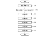
- FIG. 2 is a flow chart schematically showing an example of the procedure of the exhaust gas processing method performed in the exhaust heat recovery boiler 5 of the GTCC power generation system 1 of FIG.
- a heat exchange step S1 of bringing the exhaust gas into contact with the reheater 25 as a heat exchanger to recover the heat of the exhaust gas and at least A site after the heat exchange step S1.
- an exhaust gas processing step S3 of bringing the exhaust gas into contact with a catalyst for exhaust gas treatment comprising a perovskite type complex oxide containing Ag and Dy and containing at least Mn at the B site.
- the exhaust gas treatment method described above is characterized in that the exhaust gas is brought into contact with an exhaust gas treatment catalyst comprising a perovskite type composite oxide containing at least Ag and Dy at the A site and at least Mn at the B site. Excellent.
- a perovskite-type composite oxide containing at least Ag and Dy at A site and at least Mn at B site is superior to the catalyst having Pt supported on alumina at low temperature and has the above-mentioned VOC removal performance,
- VOCs can be efficiently removed even if the exhaust gas has a low temperature. For this reason, VOC can be removed more efficiently than before when starting the gas turbine 2.
- the perovskite type composite oxide containing at least Ag and Dy at A site and at least Mn at B site has excellent low temperature activity, so the temperature decrease of exhaust gas in heat exchange step S1 May be larger than conventional. Therefore, according to the above-mentioned exhaust gas treatment method, it is possible to efficiently remove VOC from the low temperature exhaust gas while recovering heat from the high temperature exhaust gas with high efficiency.
- FIG. 3 is a view schematically showing the configuration of a gas engine power generation system according to an embodiment of the present invention.
- the gas engine power generation system 50 includes a gas engine 52, a generator 54, a gas compressor 56, a turbocharger 58, and an exhaust gas processing device 60.
- the gas engine 52 is an engine that operates using a gas such as natural gas as a fuel, for example.
- the gas engine 52 includes a cylinder block 62, a cylinder head 63, and a flywheel 64.
- a generator 54 is connected to the flywheel 64.
- the generator 54 can generate electricity using the power output from the gas engine 52.
- each cylinder head 63 is connected to the compressor 67 of the turbocharger 58 via the air supply branch pipe 65 and the air supply pipe 66.
- a charge air cooler 68 for cooling the charge air is interposed in the charge air pipe 66. Therefore, the air compressed by the compressor 67 is cooled by the charge air cooler 68 and then supplied to the cylinder provided in the cylinder block 62 through the charge inlet of the cylinder head 63.
- a gas compressor 56 is connected to the air supply branch pipe 65 through a gas supply branch pipe 69, and fuel gas is supplied to the cylinder by the gas compressor 56.
- each cylinder head 63 is provided with an ignition device 70 having a sub combustion chamber, and fuel gas is supplied to the sub combustion chamber through the sub chamber fuel gas supply pipe 72.
- the ignition device 70 When the fuel gas in the sub combustion chamber is burned by the ignition device 70, the fuel gas in the cylinder is burned using this and the piston in the cylinder reciprocates. The reciprocating motion of the piston is converted to rotational motion through a crank mechanism and output as motive power.
- an exhaust branch pipe 74 is connected to an exhaust outlet of the cylinder head 63, and the exhaust branch pipe 74 is connected to an exhaust turbine 76 of the turbocharger 58 through an exhaust pipe 75.
- the turbocharger 58 can compress air using exhaust gas exhausted from the cylinder.
- the turbocharger 58 may have a bypass flow passage and a waste gate valve 77 interposed in the bypass flow passage to allow the exhaust gas to bypass the exhaust turbine 76 for a predetermined period.
- the exhaust turbine 76 is connected to the exhaust gas processing device 60 via the exhaust outlet pipe 80, and the exhaust gas worked by the exhaust turbine 76 is supplied to the exhaust gas processing device 60.
- the exhaust gas processing device 60 includes a housing 84 having an exhaust gas flow passage 82 therein, a denitration device 86 disposed in the exhaust gas flow passage 82, and an oxidation catalyst device 88.
- the configurations of the NOx removal device 86 and the oxidation catalyst device 88 are substantially the same as the NOx removal device 29 and the oxidation catalyst device 27 of the GTCC power generation system 1.
- the exhaust gas treatment apparatus 60 described above has an exhaust gas treatment catalyst consisting of a perovskite-type composite oxide that contains at least Ag and Dy at A site and at least Mn at B site, so it has excellent oxidation removal performance of VOC such as formaldehyde. ing.
- a perovskite-type composite oxide containing at least Ag and Dy at A site and at least Mn at B site is superior to the catalyst in which Pt is supported on alumina at low temperature, and the exhaust gas treatment is performed. According to the apparatus 60, even if the exhaust gas is at a low temperature, the VOC can be efficiently removed. Therefore, the VOC can be removed more efficiently than before when the gas engine 52 is started.
- the price of Ag is about 70 times lower than that of Pt.
- the above-mentioned exhaust gas processing apparatus 60 is cheaper than the exhaust gas processing apparatus mainly containing Pt as a noble metal.
- the exhaust gas processing device 60 requires a large amount of precious metal, so the price merit of using Ag instead of Pt as the precious metal is extremely large.
- the temperature of the exhaust gas at the turbocharger 58 is excellent because the perovskite type complex oxide containing at least Ag and Dy at A site and at least Mn at B site has excellent low temperature activity.
- the drop may be greater than in the past. Therefore, it is possible to efficiently remove the VOC from the low temperature exhaust gas while efficiently converting the thermal energy of the high temperature exhaust gas into power by the turbocharger 58.
- the above-described gas engine power generation system 50 has high thermal efficiency and is environmentally friendly, at the same time as the amount of VOC contained in the exhaust gas discharged from the exhaust gas processing device 60 is small.
- the denitration device 86 is disposed upstream of the oxidation catalyst device 88 in the flow direction of the exhaust gas, but the oxidation catalyst device 88 may be disposed upstream of the denitration device 86 .
- FIG. 4 is a flowchart schematically showing an example of the procedure of the exhaust gas processing method performed in the gas engine power generation system 50 of FIG. 3.
- the exhaust gas turbine 76 of the turbocharger 58 is rotated by the exhaust gas discharged from the gas engine 52, and the air supplied to the gas engine 52 is compressed by the compressor 67 of the turbocharger 58.
- an exhaust gas treatment step S7 in which the exhaust gas is brought into contact with an exhaust gas treatment catalyst comprising a perovskite-type composite oxide containing at least Ag and Dy at the A site and at least Mn at the B site.
- the exhaust gas treatment method described above is characterized in that the exhaust gas is brought into contact with an exhaust gas treatment catalyst comprising a perovskite type composite oxide containing at least Ag and Dy at the A site and at least Mn at the B site.
- an exhaust gas treatment catalyst comprising a perovskite type composite oxide containing at least Ag and Dy at the A site and at least Mn at the B site.
- a perovskite-type composite oxide containing at least Ag and Dy at A site and at least Mn at B site is superior to the catalyst having Pt supported on alumina at low temperature and has the above-mentioned VOC removal performance.
- VOCs can be efficiently removed even if the exhaust gas has a low temperature. Therefore, the VOC can be removed more efficiently than before when the gas engine 52 is started.
- the perovskite type composite oxide containing at least Ag and Dy at A site and at least Mn at B site has excellent low temperature activity, so the temperature decrease of the exhaust gas in the supercharging step S5 May be larger than conventional. Therefore, according to the above-described exhaust gas treatment method, VOCs can be efficiently removed from the low temperature exhaust gas while the thermal energy of the high temperature exhaust gas is efficiently converted to power by the turbocharger 58.
- the perovskite-type composite oxide has a composition represented by the general formula: Ag ⁇ Dy 1 - ⁇ MnO 3 (0.01 ⁇ ⁇ ⁇ 0.20).
- the exhaust gas treatment catalyst is made of a perovskite type composite oxide having a composition represented by the general formula: Ag ⁇ Dy 1 - ⁇ MnO 3 (0.01 ⁇ ⁇ ⁇ 0.20) , VOC, especially formaldehyde oxidation performance is excellent.
- the perovskite complex oxide has a composition represented by the general formula: Ag 0.12 Dy 0.88 MnO 3 .
- the exhaust gas treatment catalyst is composed of a perovskite-type composite oxide having a composition represented by the general formula: Ag 0.12 Dy 0.88 MnO 3 , and therefore, the oxidation performance of VOC, particularly formaldehyde Are better.
- FIG. 5 is a flow chart schematically showing an example of the procedure of the method of producing the perovskite-type composite oxide.
- a raw material preparation step S10 a raw material mixed glycine addition step S12, a dissolving step S14, a concentration step S16, a drying step S18, and a mixing step S20.
- a firing step S22 a firing step S22.
- a raw material is prepared. That is, the metal salt containing the metal atom which comprises A site, and the metal salt containing the metal atom which comprises B site are prepared.
- the metal salts are, for example, nitrate and oxalate, and may be in the form of an aqueous solution.
- the prepared raw materials are mixed. Specifically, the plurality of metal salts are mixed in a predetermined ratio such that the ratio of the number of metal atoms contained in the plurality of metal salts corresponds to the composition of the obtained perovskite-type composite oxide.
- glycine is added during the mixing of the prepared raw materials. For example, 16 moles of glycine is added per mole of the resulting perovskite complex oxide.
- the dissolving step S14 an appropriate amount of solvent is added to the mixture of the raw material and glycine to dissolve the mixture.
- the solvent is, for example, pure water.
- the concentration step S16 the solution containing the mixture obtained in the dissolution step S14 is stirred and concentrated while heating.
- the concentrate obtained in the concentration step S16 is dried and solidified at a temperature of 100 ° C. to 230 ° C.
- the mixing step S20 the solid obtained in the drying step S18 is pulverized and mixed.
- the firing step S22 the particulate material obtained in the mixing step S20 is fired, for example, at a temperature of 500 ° C. or more and 900 ° C. or less for about 4 hours, whereby a perovskite type complex oxide is obtained.
- Example 1 Preparation of catalyst ⁇
- Example 1 Using the manufacturing method of FIG. 5, a catalyst for exhaust gas treatment comprising a perovskite-type composite oxide having a composition represented by the general formula: Ag 0.12 Dy 0.88 MnO 3 was produced. Under the present circumstances, silver nitrate aqueous solution, dysprosium nitrate aqueous solution, and manganese nitrate aqueous solution were used as a raw material.
- Comparative Example 1 An exhaust gas treatment catalyst (2 wt% Pt / Al 2 O 3 ) in which 2 wt% of Pt was supported on Al 2 O 3 powder was prepared.
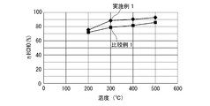
- FIG. 6 shows the relationship between the temperature of the test gas after passing through the oxidation catalyst device and the removal rate of HCHO (HHCHO) in the temperature range of 200 ° C. to 500 ° C.
- the temperature rise rate is 20 ° C./min.
- the removal rate of HCHO of Example 1 is higher than that of Comparative Example 1 in the temperature range of about 200 ° C. to 500 ° C.
- the catalyst for treating an exhaust gas comprising a perovskite-type composite oxide having a composition represented by Ag 0.12 Dy 0.88 MnO 3 is superior to the one in which Pt is supported on alumina by the HCHO oxidation removal performance.
- Example 1 when manufacturing a waste heat recovery boiler having the same degree of HCHO removal performance under the same conditions, the cost of the oxidation catalyst of Example 1 is comparable to that of the Comparative Example.
- the cost of the catalyst raw material can be reduced by 39%, which is about 61% of the cost of the oxidation catalyst 1.
- the oxidation catalyst of Example 1 when manufacturing an exhaust gas processing device for a gas turbine having the same degree of HCHO removal performance under the same conditions, the oxidation catalyst of Example 1 The cost is about 35% of the oxidation catalyst of Comparative Example 1, and the cost of the catalyst raw material can be reduced by 65%.
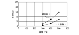
- NO 2 (nitrogen dioxide) generation performance test As in the HCHO removal performance test, a test gas is flowed to each oxidation catalyst at a flow rate of about 4500 Ncc / min while changing the temperature, and the test gas after passing the oxidation catalyst The concentration of NO 2 contained in Then, the generation rate (conversion rate) of NO (nitrogen monoxide) to NO 2 before and after passing through the oxidation catalyst device was calculated.
- FIG. 7 shows the relationship between the temperature of the test gas after passing through the oxidation catalyst device and the rate of formation of NO 2 ( ⁇ NO 2 ).
- the production rate of NO 2 of Example 1 is higher than that of Comparative Example 1 at a temperature higher than about 300 ° C.
- the oxidation catalyst consisting of a perovskite-type composite oxide having a composition represented by Ag 0.12 Dy 0.88 MnO 3 is more likely to produce NO 2 or oxidize NO 2 than the one in which Pt is supported on alumina. It can be seen that the performance is excellent.
- the removal reaction of NOx is expressed by the following three reaction formulas (1), (2) and (3), but the removal reaction by the reaction formula (2) is the fastest.
- 4NO + 4NH 3 + O 2 ⁇ 4N 2 + 6H 2 O (1) 2 NO + 2 NO 2 + 4 NH 3 ⁇ 4 N 2 + 6 H 2 O (2) 6 NO 2 + 8 NH 3 + O 2 ⁇ 7 N 2 + 12 H 2 O (3) Therefore, oxidation of NO to NO 2 by the oxidation catalyst promotes the removal of NOx by the SCR catalyst.
- the oxidation catalyst device 88 may be disposed upstream of the NOx removal device 86 in order to promote the removal of NOx by the SCR catalyst.
- the present invention is not limited to the above-described embodiments and examples, and includes modifications of the above-described embodiments and combinations of these modifications as appropriate.
Landscapes
- Chemical & Material Sciences (AREA)
- Engineering & Computer Science (AREA)
- Chemical Kinetics & Catalysis (AREA)
- Environmental & Geological Engineering (AREA)
- Materials Engineering (AREA)
- Organic Chemistry (AREA)
- Combustion & Propulsion (AREA)
- General Engineering & Computer Science (AREA)
- Mechanical Engineering (AREA)
- Health & Medical Sciences (AREA)
- Analytical Chemistry (AREA)
- Oil, Petroleum & Natural Gas (AREA)
- General Chemical & Material Sciences (AREA)
- Biomedical Technology (AREA)
- Toxicology (AREA)
- Physics & Mathematics (AREA)
- Thermal Sciences (AREA)
- Exhaust Gas Treatment By Means Of Catalyst (AREA)
- Catalysts (AREA)
- Incineration Of Waste (AREA)
Priority Applications (4)
| Application Number | Priority Date | Filing Date | Title |
|---|---|---|---|
| CN201580066574.1A CN106999846B (zh) | 2014-12-11 | 2015-09-16 | 废气处理装置、燃气轮机联合循环发电系统、燃气发动机发电系统和废气处理方法 |
| US15/533,883 US20170312689A1 (en) | 2014-12-11 | 2015-09-16 | Exhaust gas treatment device, gas turbine combined cycle power generation system, gas engine power generation system and exhaust gas treatment method |
| EP21159439.5A EP3865203B1 (en) | 2014-12-11 | 2015-09-16 | Gas turbine combined cycle power generation system, and exhaust gas treatment method |
| EP15867542.1A EP3231499B1 (en) | 2014-12-11 | 2015-09-16 | Gas engine power generation system and exhaust gas treatment method |
Applications Claiming Priority (2)
| Application Number | Priority Date | Filing Date | Title |
|---|---|---|---|
| JP2014-251062 | 2014-12-11 | ||
| JP2014251062A JP2016112483A (ja) | 2014-12-11 | 2014-12-11 | 排ガス処理装置、ガスタービンコンバインドサイクル発電システム、ガスエンジン発電システム及び排ガス処理方法 |
Publications (1)
| Publication Number | Publication Date |
|---|---|
| WO2016092931A1 true WO2016092931A1 (ja) | 2016-06-16 |
Family
ID=56107126
Family Applications (1)
| Application Number | Title | Priority Date | Filing Date |
|---|---|---|---|
| PCT/JP2015/076322 Ceased WO2016092931A1 (ja) | 2014-12-11 | 2015-09-16 | 排ガス処理装置、ガスタービンコンバインドサイクル発電システム、ガスエンジン発電システム及び排ガス処理方法 |
Country Status (5)
| Country | Link |
|---|---|
| US (1) | US20170312689A1 (enExample) |
| EP (2) | EP3865203B1 (enExample) |
| JP (1) | JP2016112483A (enExample) |
| CN (1) | CN106999846B (enExample) |
| WO (1) | WO2016092931A1 (enExample) |
Cited By (1)
| Publication number | Priority date | Publication date | Assignee | Title |
|---|---|---|---|---|
| CN110026185A (zh) * | 2018-11-23 | 2019-07-19 | 江苏中创清源科技有限公司 | 一种改性钙钛矿型催化剂及其制备方法 |
Families Citing this family (2)
| Publication number | Priority date | Publication date | Assignee | Title |
|---|---|---|---|---|
| CN112728566A (zh) * | 2020-11-29 | 2021-04-30 | 中船海洋动力部件有限公司 | 一种高效节能催化燃烧一体化装置 |
| JP2023161201A (ja) * | 2022-04-25 | 2023-11-07 | 三菱重工業株式会社 | 排ガス処理装置、燃焼設備及び排ガス処理方法 |
Citations (5)
| Publication number | Priority date | Publication date | Assignee | Title |
|---|---|---|---|---|
| JPH06182201A (ja) * | 1984-07-31 | 1994-07-05 | Hitachi Ltd | 高温で安定な触媒及びその調製法ならびにその触媒を用いて化学反応を実施する方法 |
| JP2004041868A (ja) * | 2002-07-09 | 2004-02-12 | Daihatsu Motor Co Ltd | 排ガス浄化用触媒 |
| JP2012047096A (ja) * | 2010-08-26 | 2012-03-08 | Mitsubishi Heavy Ind Ltd | 舶用脱硝システムおよびこれを備えた船舶ならびに舶用脱硝システムの制御方法 |
| JP2014161779A (ja) * | 2013-02-22 | 2014-09-08 | Mitsubishi Heavy Ind Ltd | 排熱回収ボイラ向け脱硝パックの搬入システム及びその方法、並びに排熱回収ボイラ |
| JP2015136684A (ja) * | 2014-01-24 | 2015-07-30 | 三菱重工業株式会社 | 排ガス処理用触媒、該触媒を用いた排ガス処理システム及び排ガス処理方法 |
Family Cites Families (7)
| Publication number | Priority date | Publication date | Assignee | Title |
|---|---|---|---|---|
| EP0968763A4 (en) * | 1997-10-14 | 2002-06-12 | Isuzu Ceramics Res Inst | EXHAUST GAS PURIFICATION CATALYST |
| JP4311918B2 (ja) * | 2002-07-09 | 2009-08-12 | ダイハツ工業株式会社 | ペロブスカイト型複合酸化物の製造方法 |
| JP4689574B2 (ja) | 2006-10-20 | 2011-05-25 | 本田技研工業株式会社 | 排ガス浄化用酸化触媒 |
| JP5095538B2 (ja) | 2008-07-15 | 2012-12-12 | 本田技研工業株式会社 | 排ガス浄化用酸化触媒装置 |
| US8741239B2 (en) * | 2009-02-25 | 2014-06-03 | General Electric Company | Method and apparatus for operation of CO/VOC oxidation catalyst to reduce NO2 formation for gas turbine |
| US20120102951A1 (en) * | 2010-10-29 | 2012-05-03 | Gilbert Otto Kraemer | Apparatus for reducing emissions and method of assembly |
| US20140090374A1 (en) * | 2012-10-03 | 2014-04-03 | Caterpollar Inc. | Exhaust aftertreatment system and method |
-
2014
- 2014-12-11 JP JP2014251062A patent/JP2016112483A/ja active Pending
-
2015
- 2015-09-16 EP EP21159439.5A patent/EP3865203B1/en active Active
- 2015-09-16 US US15/533,883 patent/US20170312689A1/en not_active Abandoned
- 2015-09-16 WO PCT/JP2015/076322 patent/WO2016092931A1/ja not_active Ceased
- 2015-09-16 CN CN201580066574.1A patent/CN106999846B/zh not_active Expired - Fee Related
- 2015-09-16 EP EP15867542.1A patent/EP3231499B1/en active Active
Patent Citations (5)
| Publication number | Priority date | Publication date | Assignee | Title |
|---|---|---|---|---|
| JPH06182201A (ja) * | 1984-07-31 | 1994-07-05 | Hitachi Ltd | 高温で安定な触媒及びその調製法ならびにその触媒を用いて化学反応を実施する方法 |
| JP2004041868A (ja) * | 2002-07-09 | 2004-02-12 | Daihatsu Motor Co Ltd | 排ガス浄化用触媒 |
| JP2012047096A (ja) * | 2010-08-26 | 2012-03-08 | Mitsubishi Heavy Ind Ltd | 舶用脱硝システムおよびこれを備えた船舶ならびに舶用脱硝システムの制御方法 |
| JP2014161779A (ja) * | 2013-02-22 | 2014-09-08 | Mitsubishi Heavy Ind Ltd | 排熱回収ボイラ向け脱硝パックの搬入システム及びその方法、並びに排熱回収ボイラ |
| JP2015136684A (ja) * | 2014-01-24 | 2015-07-30 | 三菱重工業株式会社 | 排ガス処理用触媒、該触媒を用いた排ガス処理システム及び排ガス処理方法 |
Cited By (1)
| Publication number | Priority date | Publication date | Assignee | Title |
|---|---|---|---|---|
| CN110026185A (zh) * | 2018-11-23 | 2019-07-19 | 江苏中创清源科技有限公司 | 一种改性钙钛矿型催化剂及其制备方法 |
Also Published As
| Publication number | Publication date |
|---|---|
| CN106999846B (zh) | 2020-03-20 |
| EP3231499A4 (en) | 2018-06-27 |
| EP3231499A1 (en) | 2017-10-18 |
| EP3231499B1 (en) | 2021-04-14 |
| CN106999846A (zh) | 2017-08-01 |
| JP2016112483A (ja) | 2016-06-23 |
| EP3865203A1 (en) | 2021-08-18 |
| US20170312689A1 (en) | 2017-11-02 |
| EP3865203B1 (en) | 2023-08-16 |
Similar Documents
| Publication | Publication Date | Title |
|---|---|---|
| JP6410202B2 (ja) | 船舶用燃焼システム | |
| AU2019399110B2 (en) | Heat utilization system, and heat generating device | |
| RU2502883C2 (ru) | Способ обработки компонентов nox и система выработки электроэнергии | |
| CN102388265B (zh) | 用于生成电功率的方法及设备 | |
| JP2023512906A (ja) | 火力発電所の排ガス処理方法 | |
| JP6153163B2 (ja) | 再熱型アンモニアガスタービン | |
| JP2009276053A5 (enExample) | ||
| WO2011105501A1 (ja) | Coシフト触媒、coシフト反応装置及びガス化ガスの精製方法 | |
| JP5935124B2 (ja) | タービン設備及び発電設備 | |
| WO2016092931A1 (ja) | 排ガス処理装置、ガスタービンコンバインドサイクル発電システム、ガスエンジン発電システム及び排ガス処理方法 | |
| CN107223193A (zh) | 用于发电设备的废气系统 | |
| JP6064498B2 (ja) | 脱硝システム | |
| WO2013153915A1 (ja) | 排気ガス浄化用触媒 | |
| JP2015136684A (ja) | 排ガス処理用触媒、該触媒を用いた排ガス処理システム及び排ガス処理方法 | |
| JP2016112483A5 (enExample) | ||
| JP6339729B2 (ja) | 排ガス処理装置及び排ガス処理用触媒の製造方法 | |
| JP4115139B2 (ja) | ガス焚き原動機の排熱回収方法およびガス焚き原動機の排熱回収装置 | |
| JP5875562B2 (ja) | 排ガス処理装置及び排ガス処理方法 | |
| JP2018167201A (ja) | ガスタービン排ガス処理用酸化触媒、並びにそれを用いた装置及び方法 | |
| JP6182036B2 (ja) | 排ガス処理用触媒及び排ガス処理装置、並びに排ガス処理用触媒の製造方法 | |
| JPH0635840B2 (ja) | Coレヒートガスタービン・コンバインドサイクルによる発電方法 | |
| CN116571081B (zh) | 联合循环机组中烟气的处理系统和方法 | |
| JP6153162B2 (ja) | Co2回収型クローズドサイクルガス化発電システム | |
| JP2013091577A (ja) | 複合型火力発電システム | |
| JP3034981B2 (ja) | 排気ガスの浄化方法 |
Legal Events
| Date | Code | Title | Description |
|---|---|---|---|
| 121 | Ep: the epo has been informed by wipo that ep was designated in this application |
Ref document number: 15867542 Country of ref document: EP Kind code of ref document: A1 |
|
| REEP | Request for entry into the european phase |
Ref document number: 2015867542 Country of ref document: EP |
|
| WWE | Wipo information: entry into national phase |
Ref document number: 15533883 Country of ref document: US |
|
| NENP | Non-entry into the national phase |
Ref country code: DE |