WO2016092931A1 - Exhaust gas treatment device, gas turbine combined cycle power generation system, gas engine power generation system, and exhaust gas treatment method - Google Patents
Exhaust gas treatment device, gas turbine combined cycle power generation system, gas engine power generation system, and exhaust gas treatment method Download PDFInfo
- Publication number
- WO2016092931A1 WO2016092931A1 PCT/JP2015/076322 JP2015076322W WO2016092931A1 WO 2016092931 A1 WO2016092931 A1 WO 2016092931A1 JP 2015076322 W JP2015076322 W JP 2015076322W WO 2016092931 A1 WO2016092931 A1 WO 2016092931A1
- Authority
- WO
- WIPO (PCT)
- Prior art keywords
- exhaust gas
- gas
- site
- turbine
- gas treatment
- Prior art date
Links
- 238000010248 power generation Methods 0.000 title claims description 40
- 238000000034 method Methods 0.000 title claims description 34
- 239000003054 catalyst Substances 0.000 claims abstract description 86
- 239000002131 composite material Substances 0.000 claims abstract description 35
- 229910052709 silver Inorganic materials 0.000 claims abstract description 35
- 229910052692 Dysprosium Inorganic materials 0.000 claims abstract description 34
- 238000012545 processing Methods 0.000 claims description 29
- 239000000203 mixture Substances 0.000 claims description 20
- 238000011144 upstream manufacturing Methods 0.000 claims description 8
- 230000005611 electricity Effects 0.000 claims description 5
- 239000007789 gas Substances 0.000 description 267
- 230000003647 oxidation Effects 0.000 description 42
- 238000007254 oxidation reaction Methods 0.000 description 42
- 239000012855 volatile organic compound Substances 0.000 description 41
- WSFSSNUMVMOOMR-UHFFFAOYSA-N Formaldehyde Chemical compound O=C WSFSSNUMVMOOMR-UHFFFAOYSA-N 0.000 description 38
- 239000011572 manganese Substances 0.000 description 29
- 238000011084 recovery Methods 0.000 description 21
- DHMQDGOQFOQNFH-UHFFFAOYSA-N Glycine Chemical compound NCC(O)=O DHMQDGOQFOQNFH-UHFFFAOYSA-N 0.000 description 12
- 230000000694 effects Effects 0.000 description 12
- 239000002994 raw material Substances 0.000 description 12
- PNEYBMLMFCGWSK-UHFFFAOYSA-N aluminium oxide Inorganic materials [O-2].[O-2].[O-2].[Al+3].[Al+3] PNEYBMLMFCGWSK-UHFFFAOYSA-N 0.000 description 10
- 230000000052 comparative effect Effects 0.000 description 10
- 229910002089 NOx Inorganic materials 0.000 description 9
- 229910052751 metal Inorganic materials 0.000 description 9
- 239000002184 metal Substances 0.000 description 9
- 238000012360 testing method Methods 0.000 description 8
- 238000003672 processing method Methods 0.000 description 7
- 239000004471 Glycine Substances 0.000 description 6
- 238000002485 combustion reaction Methods 0.000 description 6
- 239000002737 fuel gas Substances 0.000 description 6
- 229910000510 noble metal Inorganic materials 0.000 description 6
- 239000010970 precious metal Substances 0.000 description 6
- 238000006243 chemical reaction Methods 0.000 description 5
- 239000000446 fuel Substances 0.000 description 5
- 238000004519 manufacturing process Methods 0.000 description 5
- 150000003839 salts Chemical class 0.000 description 5
- XLYOFNOQVPJJNP-UHFFFAOYSA-N water Substances O XLYOFNOQVPJJNP-UHFFFAOYSA-N 0.000 description 5
- 239000007864 aqueous solution Substances 0.000 description 4
- 230000014509 gene expression Effects 0.000 description 4
- 238000010438 heat treatment Methods 0.000 description 4
- 238000002156 mixing Methods 0.000 description 4
- 239000002918 waste heat Substances 0.000 description 4
- 239000000567 combustion gas Substances 0.000 description 3
- 239000013078 crystal Substances 0.000 description 3
- 238000001035 drying Methods 0.000 description 3
- 230000001590 oxidative effect Effects 0.000 description 3
- 238000011056 performance test Methods 0.000 description 3
- 238000002360 preparation method Methods 0.000 description 3
- 229910018072 Al 2 O 3 Inorganic materials 0.000 description 2
- QGZKDVFQNNGYKY-UHFFFAOYSA-N Ammonia Chemical compound N QGZKDVFQNNGYKY-UHFFFAOYSA-N 0.000 description 2
- MWUXSHHQAYIFBG-UHFFFAOYSA-N Nitric oxide Chemical compound O=[N] MWUXSHHQAYIFBG-UHFFFAOYSA-N 0.000 description 2
- KBQHZAAAGSGFKK-UHFFFAOYSA-N dysprosium atom Chemical compound [Dy] KBQHZAAAGSGFKK-UHFFFAOYSA-N 0.000 description 2
- 238000010304 firing Methods 0.000 description 2
- VNWKTOKETHGBQD-UHFFFAOYSA-N methane Chemical compound C VNWKTOKETHGBQD-UHFFFAOYSA-N 0.000 description 2
- 238000012986 modification Methods 0.000 description 2
- 230000004048 modification Effects 0.000 description 2
- 239000000843 powder Substances 0.000 description 2
- 239000004332 silver Substances 0.000 description 2
- SQGYOTSLMSWVJD-UHFFFAOYSA-N silver(1+) nitrate Chemical compound [Ag+].[O-]N(=O)=O SQGYOTSLMSWVJD-UHFFFAOYSA-N 0.000 description 2
- 239000002904 solvent Substances 0.000 description 2
- 239000002912 waste gas Substances 0.000 description 2
- MGWGWNFMUOTEHG-UHFFFAOYSA-N 4-(3,5-dimethylphenyl)-1,3-thiazol-2-amine Chemical compound CC1=CC(C)=CC(C=2N=C(N)SC=2)=C1 MGWGWNFMUOTEHG-UHFFFAOYSA-N 0.000 description 1
- QXPQVUQBEBHHQP-UHFFFAOYSA-N 5,6,7,8-tetrahydro-[1]benzothiolo[2,3-d]pyrimidin-4-amine Chemical compound C1CCCC2=C1SC1=C2C(N)=NC=N1 QXPQVUQBEBHHQP-UHFFFAOYSA-N 0.000 description 1
- PWHULOQIROXLJO-UHFFFAOYSA-N Manganese Chemical compound [Mn] PWHULOQIROXLJO-UHFFFAOYSA-N 0.000 description 1
- 229910002651 NO3 Inorganic materials 0.000 description 1
- NHNBFGGVMKEFGY-UHFFFAOYSA-N Nitrate Chemical compound [O-][N+]([O-])=O NHNBFGGVMKEFGY-UHFFFAOYSA-N 0.000 description 1
- MUBZPKHOEPUJKR-UHFFFAOYSA-N Oxalic acid Chemical compound OC(=O)C(O)=O MUBZPKHOEPUJKR-UHFFFAOYSA-N 0.000 description 1
- 239000002253 acid Substances 0.000 description 1
- 150000001299 aldehydes Chemical class 0.000 description 1
- 229910021529 ammonia Inorganic materials 0.000 description 1
- QVGXLLKOCUKJST-UHFFFAOYSA-N atomic oxygen Chemical compound [O] QVGXLLKOCUKJST-UHFFFAOYSA-N 0.000 description 1
- 230000015572 biosynthetic process Effects 0.000 description 1
- 238000009835 boiling Methods 0.000 description 1
- 239000000919 ceramic Substances 0.000 description 1
- 239000012141 concentrate Substances 0.000 description 1
- 238000001816 cooling Methods 0.000 description 1
- 238000011161 development Methods 0.000 description 1
- 238000006073 displacement reaction Methods 0.000 description 1
- 238000004090 dissolution Methods 0.000 description 1
- 238000011156 evaluation Methods 0.000 description 1
- 229930195733 hydrocarbon Natural products 0.000 description 1
- 150000002430 hydrocarbons Chemical class 0.000 description 1
- 229910052748 manganese Inorganic materials 0.000 description 1
- MIVBAHRSNUNMPP-UHFFFAOYSA-N manganese(2+);dinitrate Chemical compound [Mn+2].[O-][N+]([O-])=O.[O-][N+]([O-])=O MIVBAHRSNUNMPP-UHFFFAOYSA-N 0.000 description 1
- 239000000463 material Substances 0.000 description 1
- 229910044991 metal oxide Inorganic materials 0.000 description 1
- 150000004706 metal oxides Chemical class 0.000 description 1
- WSFSSNUMVMOOMR-NJFSPNSNSA-N methanone Chemical compound O=[14CH2] WSFSSNUMVMOOMR-NJFSPNSNSA-N 0.000 description 1
- 239000003345 natural gas Substances 0.000 description 1
- JCXJVPUVTGWSNB-UHFFFAOYSA-N nitrogen dioxide Inorganic materials O=[N]=O JCXJVPUVTGWSNB-UHFFFAOYSA-N 0.000 description 1
- 239000001301 oxygen Substances 0.000 description 1
- 229910052760 oxygen Inorganic materials 0.000 description 1
- RVTZCBVAJQQJTK-UHFFFAOYSA-N oxygen(2-);zirconium(4+) Chemical compound [O-2].[O-2].[Zr+4] RVTZCBVAJQQJTK-UHFFFAOYSA-N 0.000 description 1
- 239000002245 particle Substances 0.000 description 1
- 239000011236 particulate material Substances 0.000 description 1
- 229910052697 platinum Inorganic materials 0.000 description 1
- 229910001961 silver nitrate Inorganic materials 0.000 description 1
- 239000007787 solid Substances 0.000 description 1
- 239000000243 solution Substances 0.000 description 1
- 239000002699 waste material Substances 0.000 description 1
- 229910052727 yttrium Inorganic materials 0.000 description 1
- 229910001928 zirconium oxide Inorganic materials 0.000 description 1
Images


Classifications
-
- B—PERFORMING OPERATIONS; TRANSPORTING
- B01—PHYSICAL OR CHEMICAL PROCESSES OR APPARATUS IN GENERAL
- B01D—SEPARATION
- B01D53/00—Separation of gases or vapours; Recovering vapours of volatile solvents from gases; Chemical or biological purification of waste gases, e.g. engine exhaust gases, smoke, fumes, flue gases, aerosols
- B01D53/34—Chemical or biological purification of waste gases
- B01D53/92—Chemical or biological purification of waste gases of engine exhaust gases
- B01D53/94—Chemical or biological purification of waste gases of engine exhaust gases by catalytic processes
- B01D53/944—Simultaneously removing carbon monoxide, hydrocarbons or carbon making use of oxidation catalysts
-
- B—PERFORMING OPERATIONS; TRANSPORTING
- B01—PHYSICAL OR CHEMICAL PROCESSES OR APPARATUS IN GENERAL
- B01D—SEPARATION
- B01D53/00—Separation of gases or vapours; Recovering vapours of volatile solvents from gases; Chemical or biological purification of waste gases, e.g. engine exhaust gases, smoke, fumes, flue gases, aerosols
- B01D53/34—Chemical or biological purification of waste gases
- B01D53/74—General processes for purification of waste gases; Apparatus or devices specially adapted therefor
- B01D53/86—Catalytic processes
- B01D53/8668—Removing organic compounds not provided for in B01D53/8603 - B01D53/8665
-
- B—PERFORMING OPERATIONS; TRANSPORTING
- B01—PHYSICAL OR CHEMICAL PROCESSES OR APPARATUS IN GENERAL
- B01D—SEPARATION
- B01D53/00—Separation of gases or vapours; Recovering vapours of volatile solvents from gases; Chemical or biological purification of waste gases, e.g. engine exhaust gases, smoke, fumes, flue gases, aerosols
- B01D53/34—Chemical or biological purification of waste gases
- B01D53/74—General processes for purification of waste gases; Apparatus or devices specially adapted therefor
- B01D53/86—Catalytic processes
-
- B—PERFORMING OPERATIONS; TRANSPORTING
- B01—PHYSICAL OR CHEMICAL PROCESSES OR APPARATUS IN GENERAL
- B01J—CHEMICAL OR PHYSICAL PROCESSES, e.g. CATALYSIS OR COLLOID CHEMISTRY; THEIR RELEVANT APPARATUS
- B01J23/00—Catalysts comprising metals or metal oxides or hydroxides, not provided for in group B01J21/00
- B01J23/002—Mixed oxides other than spinels, e.g. perovskite
-
- B—PERFORMING OPERATIONS; TRANSPORTING
- B01—PHYSICAL OR CHEMICAL PROCESSES OR APPARATUS IN GENERAL
- B01J—CHEMICAL OR PHYSICAL PROCESSES, e.g. CATALYSIS OR COLLOID CHEMISTRY; THEIR RELEVANT APPARATUS
- B01J23/00—Catalysts comprising metals or metal oxides or hydroxides, not provided for in group B01J21/00
- B01J23/38—Catalysts comprising metals or metal oxides or hydroxides, not provided for in group B01J21/00 of noble metals
- B01J23/54—Catalysts comprising metals or metal oxides or hydroxides, not provided for in group B01J21/00 of noble metals combined with metals, oxides or hydroxides provided for in groups B01J23/02 - B01J23/36
- B01J23/66—Silver or gold
- B01J23/68—Silver or gold with arsenic, antimony, bismuth, vanadium, niobium, tantalum, polonium, chromium, molybdenum, tungsten, manganese, technetium or rhenium
- B01J23/688—Silver or gold with arsenic, antimony, bismuth, vanadium, niobium, tantalum, polonium, chromium, molybdenum, tungsten, manganese, technetium or rhenium with manganese, technetium or rhenium
-
- B—PERFORMING OPERATIONS; TRANSPORTING
- B01—PHYSICAL OR CHEMICAL PROCESSES OR APPARATUS IN GENERAL
- B01J—CHEMICAL OR PHYSICAL PROCESSES, e.g. CATALYSIS OR COLLOID CHEMISTRY; THEIR RELEVANT APPARATUS
- B01J37/00—Processes, in general, for preparing catalysts; Processes, in general, for activation of catalysts
- B01J37/04—Mixing
-
- B—PERFORMING OPERATIONS; TRANSPORTING
- B01—PHYSICAL OR CHEMICAL PROCESSES OR APPARATUS IN GENERAL
- B01J—CHEMICAL OR PHYSICAL PROCESSES, e.g. CATALYSIS OR COLLOID CHEMISTRY; THEIR RELEVANT APPARATUS
- B01J37/00—Processes, in general, for preparing catalysts; Processes, in general, for activation of catalysts
- B01J37/08—Heat treatment
-
- F—MECHANICAL ENGINEERING; LIGHTING; HEATING; WEAPONS; BLASTING
- F01—MACHINES OR ENGINES IN GENERAL; ENGINE PLANTS IN GENERAL; STEAM ENGINES
- F01K—STEAM ENGINE PLANTS; STEAM ACCUMULATORS; ENGINE PLANTS NOT OTHERWISE PROVIDED FOR; ENGINES USING SPECIAL WORKING FLUIDS OR CYCLES
- F01K23/00—Plants characterised by more than one engine delivering power external to the plant, the engines being driven by different fluids
- F01K23/02—Plants characterised by more than one engine delivering power external to the plant, the engines being driven by different fluids the engine cycles being thermally coupled
- F01K23/06—Plants characterised by more than one engine delivering power external to the plant, the engines being driven by different fluids the engine cycles being thermally coupled combustion heat from one cycle heating the fluid in another cycle
- F01K23/10—Plants characterised by more than one engine delivering power external to the plant, the engines being driven by different fluids the engine cycles being thermally coupled combustion heat from one cycle heating the fluid in another cycle with exhaust fluid of one cycle heating the fluid in another cycle
-
- F—MECHANICAL ENGINEERING; LIGHTING; HEATING; WEAPONS; BLASTING
- F01—MACHINES OR ENGINES IN GENERAL; ENGINE PLANTS IN GENERAL; STEAM ENGINES
- F01N—GAS-FLOW SILENCERS OR EXHAUST APPARATUS FOR MACHINES OR ENGINES IN GENERAL; GAS-FLOW SILENCERS OR EXHAUST APPARATUS FOR INTERNAL COMBUSTION ENGINES
- F01N3/00—Exhaust or silencing apparatus having means for purifying, rendering innocuous, or otherwise treating exhaust
- F01N3/08—Exhaust or silencing apparatus having means for purifying, rendering innocuous, or otherwise treating exhaust for rendering innocuous
- F01N3/10—Exhaust or silencing apparatus having means for purifying, rendering innocuous, or otherwise treating exhaust for rendering innocuous by thermal or catalytic conversion of noxious components of exhaust
- F01N3/18—Exhaust or silencing apparatus having means for purifying, rendering innocuous, or otherwise treating exhaust for rendering innocuous by thermal or catalytic conversion of noxious components of exhaust characterised by methods of operation; Control
- F01N3/20—Exhaust or silencing apparatus having means for purifying, rendering innocuous, or otherwise treating exhaust for rendering innocuous by thermal or catalytic conversion of noxious components of exhaust characterised by methods of operation; Control specially adapted for catalytic conversion ; Methods of operation or control of catalytic converters
-
- F—MECHANICAL ENGINEERING; LIGHTING; HEATING; WEAPONS; BLASTING
- F23—COMBUSTION APPARATUS; COMBUSTION PROCESSES
- F23G—CREMATION FURNACES; CONSUMING WASTE PRODUCTS BY COMBUSTION
- F23G7/00—Incinerators or other apparatus for consuming industrial waste, e.g. chemicals
- F23G7/06—Incinerators or other apparatus for consuming industrial waste, e.g. chemicals of waste gases or noxious gases, e.g. exhaust gases
- F23G7/07—Incinerators or other apparatus for consuming industrial waste, e.g. chemicals of waste gases or noxious gases, e.g. exhaust gases in which combustion takes place in the presence of catalytic material
-
- F—MECHANICAL ENGINEERING; LIGHTING; HEATING; WEAPONS; BLASTING
- F23—COMBUSTION APPARATUS; COMBUSTION PROCESSES
- F23R—GENERATING COMBUSTION PRODUCTS OF HIGH PRESSURE OR HIGH VELOCITY, e.g. GAS-TURBINE COMBUSTION CHAMBERS
- F23R3/00—Continuous combustion chambers using liquid or gaseous fuel
- F23R3/40—Continuous combustion chambers using liquid or gaseous fuel characterised by the use of catalytic means
-
- B—PERFORMING OPERATIONS; TRANSPORTING
- B01—PHYSICAL OR CHEMICAL PROCESSES OR APPARATUS IN GENERAL
- B01D—SEPARATION
- B01D2255/00—Catalysts
- B01D2255/10—Noble metals or compounds thereof
- B01D2255/104—Silver
-
- B—PERFORMING OPERATIONS; TRANSPORTING
- B01—PHYSICAL OR CHEMICAL PROCESSES OR APPARATUS IN GENERAL
- B01D—SEPARATION
- B01D2255/00—Catalysts
- B01D2255/20—Metals or compounds thereof
- B01D2255/206—Rare earth metals
-
- B—PERFORMING OPERATIONS; TRANSPORTING
- B01—PHYSICAL OR CHEMICAL PROCESSES OR APPARATUS IN GENERAL
- B01D—SEPARATION
- B01D2255/00—Catalysts
- B01D2255/20—Metals or compounds thereof
- B01D2255/207—Transition metals
- B01D2255/2073—Manganese
-
- B—PERFORMING OPERATIONS; TRANSPORTING
- B01—PHYSICAL OR CHEMICAL PROCESSES OR APPARATUS IN GENERAL
- B01D—SEPARATION
- B01D2255/00—Catalysts
- B01D2255/40—Mixed oxides
- B01D2255/402—Perovskites
-
- B—PERFORMING OPERATIONS; TRANSPORTING
- B01—PHYSICAL OR CHEMICAL PROCESSES OR APPARATUS IN GENERAL
- B01D—SEPARATION
- B01D2257/00—Components to be removed
- B01D2257/70—Organic compounds not provided for in groups B01D2257/00 - B01D2257/602
- B01D2257/708—Volatile organic compounds V.O.C.'s
-
- B—PERFORMING OPERATIONS; TRANSPORTING
- B01—PHYSICAL OR CHEMICAL PROCESSES OR APPARATUS IN GENERAL
- B01D—SEPARATION
- B01D2258/00—Sources of waste gases
- B01D2258/02—Other waste gases
- B01D2258/0283—Flue gases
-
- Y—GENERAL TAGGING OF NEW TECHNOLOGICAL DEVELOPMENTS; GENERAL TAGGING OF CROSS-SECTIONAL TECHNOLOGIES SPANNING OVER SEVERAL SECTIONS OF THE IPC; TECHNICAL SUBJECTS COVERED BY FORMER USPC CROSS-REFERENCE ART COLLECTIONS [XRACs] AND DIGESTS
- Y02—TECHNOLOGIES OR APPLICATIONS FOR MITIGATION OR ADAPTATION AGAINST CLIMATE CHANGE
- Y02E—REDUCTION OF GREENHOUSE GAS [GHG] EMISSIONS, RELATED TO ENERGY GENERATION, TRANSMISSION OR DISTRIBUTION
- Y02E20/00—Combustion technologies with mitigation potential
- Y02E20/12—Heat utilisation in combustion or incineration of waste
-
- Y—GENERAL TAGGING OF NEW TECHNOLOGICAL DEVELOPMENTS; GENERAL TAGGING OF CROSS-SECTIONAL TECHNOLOGIES SPANNING OVER SEVERAL SECTIONS OF THE IPC; TECHNICAL SUBJECTS COVERED BY FORMER USPC CROSS-REFERENCE ART COLLECTIONS [XRACs] AND DIGESTS
- Y02—TECHNOLOGIES OR APPLICATIONS FOR MITIGATION OR ADAPTATION AGAINST CLIMATE CHANGE
- Y02E—REDUCTION OF GREENHOUSE GAS [GHG] EMISSIONS, RELATED TO ENERGY GENERATION, TRANSMISSION OR DISTRIBUTION
- Y02E20/00—Combustion technologies with mitigation potential
- Y02E20/16—Combined cycle power plant [CCPP], or combined cycle gas turbine [CCGT]
Definitions
- the present disclosure relates to an exhaust gas processing device, a gas turbine combined cycle power generation system, a gas engine power generation system, and an exhaust gas processing method.
- Pt was supported on alumina as a catalyst for oxidizing and removing aldehydes, which are unburned products of fuel, mainly formaldehyde from the exhaust gas of gas turbines and gas engines. The thing is used.
- Patent Document 1 As an oxidation catalyst for oxidizing inclusions such as particulates and high-boiling hydrocarbons contained in exhaust gas of an internal combustion engine, Patent Document 1 has a general formula: Y 1-x Ag x MnO 3 (0.01 ⁇ Disclosed is an oxidation catalyst having a composition represented by x ⁇ 0.15).
- Patent Document 3 describes a composite metal oxide having a composition represented by the general formula: Y 0.95 Ag 0.05 MnO 3 Discloses a catalyst comprising a porous body of a mixture of zirconium oxide.
- An object of at least one embodiment of the present invention is to provide an exhaust gas processing device, a gas turbine combined cycle power generation system, a gas engine power generation system, and an exhaust gas processing method, which are excellent in VOC removal performance.
- the present inventors have repeatedly conducted various studies to develop a novel exhaust gas processing catalyst excellent in the oxidation performance of VOC, particularly formaldehyde, and show that Ag (silver) and Dy (dysprosium) are promising as elements of A site.
- the present invention has been conceived.
- An exhaust gas processing device is an exhaust gas processing device capable of processing the exhaust gas of a gas turbine or a gas engine,
- a catalyst for exhaust gas treatment is provided comprising a perovskite-type composite oxide containing at least Ag and Dy at A site and at least Mn at B site.
- the exhaust gas treatment apparatus of the above configuration (1) has an exhaust gas treatment catalyst comprising a perovskite type composite oxide containing at least Ag and Dy at A site and at least Mn at B site, therefore oxidation removal of VOC such as formaldehyde It is excellent in performance.
- a perovskite-type composite oxide containing at least Ag and Dy at A site and at least Mn at B site is superior to the catalyst having Pt supported on alumina at low temperature, and has the above-mentioned constitution
- VOCs can be efficiently removed. For this reason, VOC can be removed more efficiently than before when starting a gas turbine or gas engine.
- the exhaust gas processing system of the above configuration (1) is cheaper than the exhaust gas processing system mainly containing Pt as a noble metal.
- the exhaust gas processing device requires a large amount of precious metal, so the price merit of using Ag instead of Pt as the precious metal is extremely large.
- the exhaust gas processing device further includes a heat exchanger capable of recovering the heat of the exhaust gas of the gas turbine.
- the heat of the exhaust gas can be effectively used by recovering the heat of the exhaust gas by the heat exchanger.
- the temperature drop of the exhaust gas in the heat exchanger upstream of the exhaust gas treatment catalyst May be larger than conventional. Therefore, VOC can be efficiently removed from the low temperature exhaust gas while heating the steam with high efficiency using the high temperature exhaust gas.
- the perovskite complex oxide has a composition represented by a general formula: Ag ⁇ Dy 1 - ⁇ MnO 3 (0.01 ⁇ ⁇ ⁇ 0.20).
- the perovskite complex oxide has a composition represented by a general formula: Ag 0.12 Dy 0.88 MnO 3 .
- a gas turbine combined cycle power generation system With gas turbines, With a steam turbine, At least one generator capable of generating electricity by the power of the gas turbine and the steam turbine;
- An exhaust gas treatment device capable of treating the exhaust gas of the gas turbine;
- the exhaust gas treatment device is A catalyst for treating an exhaust gas comprising a perovskite complex oxide containing at least Ag and Dy at A site and at least Mn at B site, A heat exchanger disposed upstream of the exhaust gas treatment catalyst in the flow direction of the exhaust gas and capable of performing heat exchange between the exhaust gas and the steam supplied to the steam turbine; Have.
- the exhaust gas processing device removes VOCs from the exhaust gas, while providing the heat of the exhaust gas to the steam to generate power using the power of the steam turbine.
- the exhaust gas processing apparatus since the perovskite type composite oxide has excellent low temperature activity, VOCs can be efficiently removed even when the exhaust gas is at low temperature when the gas turbine combined cycle power generation system is started. Further, since the perovskite type complex oxide containing at least Ag and Dy at A site and at least Mn at B site has excellent low temperature activity, the heat exchanger upstream of the exhaust gas treatment catalyst in the flow direction of the exhaust gas The temperature reduction of the exhaust gas at the end may be greater than in the prior art.
- VOC can be efficiently removed from the low temperature exhaust gas while heating the steam with high efficiency using the high temperature exhaust gas.
- the gas turbine combined cycle power generation system of the above configuration (5) is environmentally friendly, has a high thermal efficiency and at the same time has a small amount of VOC contained in the exhaust gas discharged from the exhaust gas processing device.
- a gas engine power generation system With a gas engine, A generator capable of generating electricity by the power of the gas engine; A turbocharger capable of compressing air supplied to the gas engine; An exhaust gas treatment device capable of treating the exhaust gas of the gas engine;
- the exhaust gas treating apparatus has an exhaust gas treating catalyst comprising a perovskite type composite oxide containing at least Ag and Dy at A site and at least Mn at B site, An exhaust gas turbine of the turbocharger is disposed in an exhaust gas flow path extending between the gas engine and the exhaust gas treatment device.
- the exhaust gas treatment device removes VOCs in the exhaust gas.
- VOCs can be efficiently removed even when the exhaust gas is low temperature at the start of the gas engine power generation system.
- the perovskite type complex oxide containing at least Ag and Dy at A site and at least Mn at B site has excellent low temperature activity, the temperature decrease of the exhaust gas in the turbocharger may become larger than before . Therefore, it is possible to efficiently remove the VOC from the low temperature exhaust gas while efficiently converting the thermal energy of the high temperature exhaust gas into power by the turbocharger.
- the gas engine power generation system of the above configuration (6) has high thermal efficiency and at the same time is environmentally friendly, as the amount of VOC contained in the exhaust gas discharged from the exhaust gas processing device is small.
- An exhaust gas treatment step is provided in which an exhaust gas discharged from a gas turbine or gas engine is brought into contact with an exhaust gas treatment catalyst consisting of a perovskite type composite oxide containing at least Ag and Dy at A site and at least Mn at B site.
- the exhaust gas is brought into contact with an exhaust gas treatment catalyst comprising a perovskite type complex oxide containing at least Ag and Dy at A site and at least Mn at B site.
- an exhaust gas treatment catalyst comprising a perovskite type complex oxide containing at least Ag and Dy at A site and at least Mn at B site.
- a perovskite-type composite oxide containing at least Ag and Dy at A site and at least Mn at B site is superior to the catalyst having Pt supported on alumina at low temperature, and has the above-mentioned constitution
- the exhaust gas treatment method of (7) even if the exhaust gas has a low temperature, VOCs can be efficiently removed. For this reason, VOC can be removed more efficiently than before when starting a gas turbine or gas engine.
- the exhaust gas treatment method further includes, before the exhaust gas treatment step, a heat exchange step of bringing the exhaust gas discharged from the gas turbine into contact with a heat exchanger to recover the heat of the exhaust gas.
- the temperature of the exhaust gas in the heat exchange step is excellent because the perovskite type composite oxide containing at least Ag and Dy at A site and at least Mn at B site has excellent low temperature activity.
- the drop may be greater than conventional. Therefore, according to the exhaust gas treatment method of the above configuration (8), it is possible to efficiently remove the VOC from the low temperature exhaust gas while recovering heat from the high temperature exhaust gas with high efficiency.
- the exhaust gas treatment method prior to the exhaust gas treatment step, an exhaust gas turbine discharged from the gas engine is rotated to rotate an exhaust turbine of a turbocharger, and a compressor of the turbocharger compresses air supplied to the gas engine.
- the method further comprises the steps.
- the temperature of the exhaust gas in the supercharging step is excellent because the perovskite type composite oxide containing at least Ag and Dy at A site and at least Mn at B site has excellent low temperature activity.
- the drop may be greater than conventional. Therefore, according to the exhaust gas treatment method of the above configuration (9), it is possible to efficiently remove VOC from the low temperature exhaust gas while efficiently converting the thermal energy of the high temperature exhaust gas into power by the turbocharger. .
- an exhaust gas treatment device a gas turbine combined cycle power generation system, a gas engine power generation system, and an exhaust gas treatment method with excellent VOC removal performance are provided.
- expressions that indicate that things such as “identical”, “equal” and “homogeneous” are equal states not only represent strictly equal states, but also have tolerances or differences with which the same function can be obtained. It also represents the existing state.
- expressions representing shapes such as quadrilateral shapes and cylindrical shapes not only represent shapes such as rectangular shapes and cylindrical shapes in a geometrically strict sense, but also uneven portions and chamfers within the range where the same effect can be obtained. The shape including a part etc. shall also be expressed.
- the expressions “comprising”, “having”, “having”, “including” or “having” one component are not exclusive expressions excluding the presence of other components.
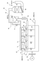
- FIG. 1 is a view schematically showing the configuration of a GTCC (gas turbine combined cycle) power generation system according to an embodiment of the present invention.
- the GTCC power generation system 1 is a combined power generation system, and includes a gas turbine 2, a steam turbine 3, an exhaust heat recovery boiler 5, and generators 7 and 9.
- the GTCC power generation system may be for business use or private use.
- the gas turbine 2 includes a compressor 11, a combustor 13, and a turbine 15.
- the compressor 11 compresses air using a part of the output of the turbine 15, and the compressed air is supplied to the combustor 13.
- the combustor 13 is supplied with compressed air and fuel to burn the fuel.
- the combustion gas generated by the fuel combustion is supplied to the turbine 15, and the turbine 15 outputs power using the combustion gas.
- the turbine 15 is connected to the generator 7, and the generator 7 generates power using a part of the power of the turbine 15.
- the combustion gas (hereinafter, also referred to as exhaust gas) that has been worked by the turbine 15 is supplied to the exhaust heat recovery boiler 5.
- the waste heat recovery boiler 5 is not only an exhaust gas treatment device for treating and purifying the exhaust gas, but also a heat exchange device for generating steam by using the heat (exhaust heat) of the exhaust gas.
- the exhaust heat recovery boiler 5 includes a housing 17 having an exhaust gas flow path 16 therein, an economizer 18, a header 19, an evaporator 21, a superheater 23, and a reheater 25.
- the economizer 18, the evaporator 21, the superheater 23, and the reheater 25 are disposed in the exhaust gas flow path 16, and are heat exchangers that perform heat exchange between the exhaust gas and water (steam).
- the water is heated by the economizer 18, the evaporator 21 and the superheater 23 to obtain superheated steam.
- the exhaust heat recovery boiler 5 has an oxidation catalyst device 27 and a denitration device 29 respectively disposed in the exhaust gas passage 16 in the housing 17 as an exhaust gas treatment device for purifying the exhaust gas flowing through the exhaust gas passage 16.
- the NOx removal device 29 is composed of an SCR catalyst (selective reduction catalyst), and has a function of removing NOx contained in the exhaust gas.
- the oxidation catalyst device 27 will be described later.
- the superheated steam generated by the exhaust heat recovery boiler 5 is supplied to the steam turbine 3.
- the steam turbine 3 is connected to a generator 9, the steam turbine 3 outputs power using steam, and the generator 9 generates power using power of the steam turbine 3.
- the steam turbine 3 has a high pressure turbine 31, an intermediate pressure turbine 33 and a low pressure turbine 35, and each of the high pressure turbine 31, the intermediate pressure turbine 33 and the low pressure turbine 35 outputs power using steam.
- Superheated steam is returned to the waste heat recovery boiler 5 once after working in the high pressure turbine 31 and supplied to the reheater 25.
- the reheater 25 heats the steam, and the heated steam is supplied to the medium pressure turbine 33 of the steam turbine 3.
- a condenser 37 is connected to the low pressure turbine 35, and the steam discharged from the low pressure turbine 35 of the steam turbine 3 is condensed by the condenser 37 and becomes water.
- the condenser 37 is connected to the exhaust heat recovery boiler 5 via a condensate pump 39, and the water obtained by the condenser 37 is supplied to the economizer 18 of the exhaust heat recovery boiler 5 by the condensate pump 39. Ru.
- the oxidation catalyst device 27 of the above-described exhaust heat recovery boiler is disposed, for example, in the portion of the exhaust gas flow path 16 extending between the reheater 25 and the superheater 23.
- the oxidation catalyst device 27 has a carrier and a catalyst (hereinafter also referred to as an oxidation catalyst or exhaust gas treatment catalyst) held by the carrier, and for example, the carrier is constituted by a metal or ceramic honeycomb .
- the oxidation catalyst is composed of a perovskite-type composite oxide containing at least Ag (silver) and Dy (dysprosium) at the A site and at least Mn (manganese) at the B site.
- the A site is located at the corner of the unit cell
- the B site is located at the body center of the unit cell
- the oxygen is located at the face center of the unit cell.
- the crystal system is not limited to cubic crystals.
- the exhaust heat recovery boiler 5 which is an exhaust gas treatment apparatus of the GTCC power generation system 1 described above, has an exhaust gas treatment catalyst comprising an perovskite complex oxide containing at least Ag and Dy at A site and at least Mn at B site. It is excellent in the oxidation removal performance of VOC such as formaldehyde.
- a perovskite-type composite oxide containing at least Ag and Dy at A site and at least Mn at B site is superior to the catalyst in which Pt is supported on alumina at low temperature, and the exhaust heat is excellent.
- VOCs can be efficiently removed even if the exhaust gas temperature is low. For this reason, VOC can be removed more efficiently than before when starting the gas turbine 2.
- the exhaust heat recovery boiler 5 is cheaper than the exhaust gas processing device mainly containing Pt as a noble metal.
- the waste heat recovery boiler 5 requires a large amount of precious metal, so the price merit of using Ag instead of Pt as the precious metal is extremely large.
- the above-described exhaust heat recovery boiler 5 can effectively utilize the heat of the exhaust gas by recovering the heat of the exhaust gas with the heat exchanger.
- the heat exchanger upstream of oxidation catalyst device 27 in the flow direction of the exhaust gas The temperature reduction of the exhaust gas at the end may be greater than in the prior art. Therefore, VOC can be efficiently removed from the low temperature exhaust gas while heating the steam with high efficiency using the high temperature exhaust gas.
- the GTCC power generation system 1 has high thermal efficiency and at the same time is environmentally friendly, as the amount of VOC contained in the exhaust gas discharged from the exhaust heat recovery boiler 5 is small.
- the oxidation catalyst device 27 is disposed in the portion of the exhaust gas flow path 16 extending between the reheater 25 and the superheater 23, but the superheater 23 and the evaporator 21 are The oxidation catalyst device 27 may be disposed in the portion of the exhaust gas flow path 16 extending between the two.
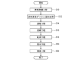
- FIG. 2 is a flow chart schematically showing an example of the procedure of the exhaust gas processing method performed in the exhaust heat recovery boiler 5 of the GTCC power generation system 1 of FIG.
- a heat exchange step S1 of bringing the exhaust gas into contact with the reheater 25 as a heat exchanger to recover the heat of the exhaust gas and at least A site after the heat exchange step S1.
- an exhaust gas processing step S3 of bringing the exhaust gas into contact with a catalyst for exhaust gas treatment comprising a perovskite type complex oxide containing Ag and Dy and containing at least Mn at the B site.
- the exhaust gas treatment method described above is characterized in that the exhaust gas is brought into contact with an exhaust gas treatment catalyst comprising a perovskite type composite oxide containing at least Ag and Dy at the A site and at least Mn at the B site. Excellent.
- a perovskite-type composite oxide containing at least Ag and Dy at A site and at least Mn at B site is superior to the catalyst having Pt supported on alumina at low temperature and has the above-mentioned VOC removal performance,
- VOCs can be efficiently removed even if the exhaust gas has a low temperature. For this reason, VOC can be removed more efficiently than before when starting the gas turbine 2.
- the perovskite type composite oxide containing at least Ag and Dy at A site and at least Mn at B site has excellent low temperature activity, so the temperature decrease of exhaust gas in heat exchange step S1 May be larger than conventional. Therefore, according to the above-mentioned exhaust gas treatment method, it is possible to efficiently remove VOC from the low temperature exhaust gas while recovering heat from the high temperature exhaust gas with high efficiency.
- FIG. 3 is a view schematically showing the configuration of a gas engine power generation system according to an embodiment of the present invention.
- the gas engine power generation system 50 includes a gas engine 52, a generator 54, a gas compressor 56, a turbocharger 58, and an exhaust gas processing device 60.
- the gas engine 52 is an engine that operates using a gas such as natural gas as a fuel, for example.
- the gas engine 52 includes a cylinder block 62, a cylinder head 63, and a flywheel 64.
- a generator 54 is connected to the flywheel 64.
- the generator 54 can generate electricity using the power output from the gas engine 52.
- each cylinder head 63 is connected to the compressor 67 of the turbocharger 58 via the air supply branch pipe 65 and the air supply pipe 66.
- a charge air cooler 68 for cooling the charge air is interposed in the charge air pipe 66. Therefore, the air compressed by the compressor 67 is cooled by the charge air cooler 68 and then supplied to the cylinder provided in the cylinder block 62 through the charge inlet of the cylinder head 63.
- a gas compressor 56 is connected to the air supply branch pipe 65 through a gas supply branch pipe 69, and fuel gas is supplied to the cylinder by the gas compressor 56.
- each cylinder head 63 is provided with an ignition device 70 having a sub combustion chamber, and fuel gas is supplied to the sub combustion chamber through the sub chamber fuel gas supply pipe 72.
- the ignition device 70 When the fuel gas in the sub combustion chamber is burned by the ignition device 70, the fuel gas in the cylinder is burned using this and the piston in the cylinder reciprocates. The reciprocating motion of the piston is converted to rotational motion through a crank mechanism and output as motive power.
- an exhaust branch pipe 74 is connected to an exhaust outlet of the cylinder head 63, and the exhaust branch pipe 74 is connected to an exhaust turbine 76 of the turbocharger 58 through an exhaust pipe 75.
- the turbocharger 58 can compress air using exhaust gas exhausted from the cylinder.
- the turbocharger 58 may have a bypass flow passage and a waste gate valve 77 interposed in the bypass flow passage to allow the exhaust gas to bypass the exhaust turbine 76 for a predetermined period.
- the exhaust turbine 76 is connected to the exhaust gas processing device 60 via the exhaust outlet pipe 80, and the exhaust gas worked by the exhaust turbine 76 is supplied to the exhaust gas processing device 60.
- the exhaust gas processing device 60 includes a housing 84 having an exhaust gas flow passage 82 therein, a denitration device 86 disposed in the exhaust gas flow passage 82, and an oxidation catalyst device 88.
- the configurations of the NOx removal device 86 and the oxidation catalyst device 88 are substantially the same as the NOx removal device 29 and the oxidation catalyst device 27 of the GTCC power generation system 1.
- the exhaust gas treatment apparatus 60 described above has an exhaust gas treatment catalyst consisting of a perovskite-type composite oxide that contains at least Ag and Dy at A site and at least Mn at B site, so it has excellent oxidation removal performance of VOC such as formaldehyde. ing.
- a perovskite-type composite oxide containing at least Ag and Dy at A site and at least Mn at B site is superior to the catalyst in which Pt is supported on alumina at low temperature, and the exhaust gas treatment is performed. According to the apparatus 60, even if the exhaust gas is at a low temperature, the VOC can be efficiently removed. Therefore, the VOC can be removed more efficiently than before when the gas engine 52 is started.
- the price of Ag is about 70 times lower than that of Pt.
- the above-mentioned exhaust gas processing apparatus 60 is cheaper than the exhaust gas processing apparatus mainly containing Pt as a noble metal.
- the exhaust gas processing device 60 requires a large amount of precious metal, so the price merit of using Ag instead of Pt as the precious metal is extremely large.
- the temperature of the exhaust gas at the turbocharger 58 is excellent because the perovskite type complex oxide containing at least Ag and Dy at A site and at least Mn at B site has excellent low temperature activity.
- the drop may be greater than in the past. Therefore, it is possible to efficiently remove the VOC from the low temperature exhaust gas while efficiently converting the thermal energy of the high temperature exhaust gas into power by the turbocharger 58.
- the above-described gas engine power generation system 50 has high thermal efficiency and is environmentally friendly, at the same time as the amount of VOC contained in the exhaust gas discharged from the exhaust gas processing device 60 is small.
- the denitration device 86 is disposed upstream of the oxidation catalyst device 88 in the flow direction of the exhaust gas, but the oxidation catalyst device 88 may be disposed upstream of the denitration device 86 .
- FIG. 4 is a flowchart schematically showing an example of the procedure of the exhaust gas processing method performed in the gas engine power generation system 50 of FIG. 3.
- the exhaust gas turbine 76 of the turbocharger 58 is rotated by the exhaust gas discharged from the gas engine 52, and the air supplied to the gas engine 52 is compressed by the compressor 67 of the turbocharger 58.
- an exhaust gas treatment step S7 in which the exhaust gas is brought into contact with an exhaust gas treatment catalyst comprising a perovskite-type composite oxide containing at least Ag and Dy at the A site and at least Mn at the B site.
- the exhaust gas treatment method described above is characterized in that the exhaust gas is brought into contact with an exhaust gas treatment catalyst comprising a perovskite type composite oxide containing at least Ag and Dy at the A site and at least Mn at the B site.
- an exhaust gas treatment catalyst comprising a perovskite type composite oxide containing at least Ag and Dy at the A site and at least Mn at the B site.
- a perovskite-type composite oxide containing at least Ag and Dy at A site and at least Mn at B site is superior to the catalyst having Pt supported on alumina at low temperature and has the above-mentioned VOC removal performance.
- VOCs can be efficiently removed even if the exhaust gas has a low temperature. Therefore, the VOC can be removed more efficiently than before when the gas engine 52 is started.
- the perovskite type composite oxide containing at least Ag and Dy at A site and at least Mn at B site has excellent low temperature activity, so the temperature decrease of the exhaust gas in the supercharging step S5 May be larger than conventional. Therefore, according to the above-described exhaust gas treatment method, VOCs can be efficiently removed from the low temperature exhaust gas while the thermal energy of the high temperature exhaust gas is efficiently converted to power by the turbocharger 58.
- the perovskite-type composite oxide has a composition represented by the general formula: Ag ⁇ Dy 1 - ⁇ MnO 3 (0.01 ⁇ ⁇ ⁇ 0.20).
- the exhaust gas treatment catalyst is made of a perovskite type composite oxide having a composition represented by the general formula: Ag ⁇ Dy 1 - ⁇ MnO 3 (0.01 ⁇ ⁇ ⁇ 0.20) , VOC, especially formaldehyde oxidation performance is excellent.
- the perovskite complex oxide has a composition represented by the general formula: Ag 0.12 Dy 0.88 MnO 3 .
- the exhaust gas treatment catalyst is composed of a perovskite-type composite oxide having a composition represented by the general formula: Ag 0.12 Dy 0.88 MnO 3 , and therefore, the oxidation performance of VOC, particularly formaldehyde Are better.
- FIG. 5 is a flow chart schematically showing an example of the procedure of the method of producing the perovskite-type composite oxide.
- a raw material preparation step S10 a raw material mixed glycine addition step S12, a dissolving step S14, a concentration step S16, a drying step S18, and a mixing step S20.
- a firing step S22 a firing step S22.
- a raw material is prepared. That is, the metal salt containing the metal atom which comprises A site, and the metal salt containing the metal atom which comprises B site are prepared.
- the metal salts are, for example, nitrate and oxalate, and may be in the form of an aqueous solution.
- the prepared raw materials are mixed. Specifically, the plurality of metal salts are mixed in a predetermined ratio such that the ratio of the number of metal atoms contained in the plurality of metal salts corresponds to the composition of the obtained perovskite-type composite oxide.
- glycine is added during the mixing of the prepared raw materials. For example, 16 moles of glycine is added per mole of the resulting perovskite complex oxide.
- the dissolving step S14 an appropriate amount of solvent is added to the mixture of the raw material and glycine to dissolve the mixture.
- the solvent is, for example, pure water.
- the concentration step S16 the solution containing the mixture obtained in the dissolution step S14 is stirred and concentrated while heating.
- the concentrate obtained in the concentration step S16 is dried and solidified at a temperature of 100 ° C. to 230 ° C.
- the mixing step S20 the solid obtained in the drying step S18 is pulverized and mixed.
- the firing step S22 the particulate material obtained in the mixing step S20 is fired, for example, at a temperature of 500 ° C. or more and 900 ° C. or less for about 4 hours, whereby a perovskite type complex oxide is obtained.
- Example 1 Preparation of catalyst ⁇
- Example 1 Using the manufacturing method of FIG. 5, a catalyst for exhaust gas treatment comprising a perovskite-type composite oxide having a composition represented by the general formula: Ag 0.12 Dy 0.88 MnO 3 was produced. Under the present circumstances, silver nitrate aqueous solution, dysprosium nitrate aqueous solution, and manganese nitrate aqueous solution were used as a raw material.
- Comparative Example 1 An exhaust gas treatment catalyst (2 wt% Pt / Al 2 O 3 ) in which 2 wt% of Pt was supported on Al 2 O 3 powder was prepared.
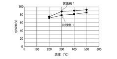
- FIG. 6 shows the relationship between the temperature of the test gas after passing through the oxidation catalyst device and the removal rate of HCHO (HHCHO) in the temperature range of 200 ° C. to 500 ° C.
- the temperature rise rate is 20 ° C./min.
- the removal rate of HCHO of Example 1 is higher than that of Comparative Example 1 in the temperature range of about 200 ° C. to 500 ° C.
- the catalyst for treating an exhaust gas comprising a perovskite-type composite oxide having a composition represented by Ag 0.12 Dy 0.88 MnO 3 is superior to the one in which Pt is supported on alumina by the HCHO oxidation removal performance.
- Example 1 when manufacturing a waste heat recovery boiler having the same degree of HCHO removal performance under the same conditions, the cost of the oxidation catalyst of Example 1 is comparable to that of the Comparative Example.
- the cost of the catalyst raw material can be reduced by 39%, which is about 61% of the cost of the oxidation catalyst 1.
- the oxidation catalyst of Example 1 when manufacturing an exhaust gas processing device for a gas turbine having the same degree of HCHO removal performance under the same conditions, the oxidation catalyst of Example 1 The cost is about 35% of the oxidation catalyst of Comparative Example 1, and the cost of the catalyst raw material can be reduced by 65%.
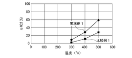
- NO 2 (nitrogen dioxide) generation performance test As in the HCHO removal performance test, a test gas is flowed to each oxidation catalyst at a flow rate of about 4500 Ncc / min while changing the temperature, and the test gas after passing the oxidation catalyst The concentration of NO 2 contained in Then, the generation rate (conversion rate) of NO (nitrogen monoxide) to NO 2 before and after passing through the oxidation catalyst device was calculated.
- FIG. 7 shows the relationship between the temperature of the test gas after passing through the oxidation catalyst device and the rate of formation of NO 2 ( ⁇ NO 2 ).
- the production rate of NO 2 of Example 1 is higher than that of Comparative Example 1 at a temperature higher than about 300 ° C.
- the oxidation catalyst consisting of a perovskite-type composite oxide having a composition represented by Ag 0.12 Dy 0.88 MnO 3 is more likely to produce NO 2 or oxidize NO 2 than the one in which Pt is supported on alumina. It can be seen that the performance is excellent.
- the removal reaction of NOx is expressed by the following three reaction formulas (1), (2) and (3), but the removal reaction by the reaction formula (2) is the fastest.
- 4NO + 4NH 3 + O 2 ⁇ 4N 2 + 6H 2 O (1) 2 NO + 2 NO 2 + 4 NH 3 ⁇ 4 N 2 + 6 H 2 O (2) 6 NO 2 + 8 NH 3 + O 2 ⁇ 7 N 2 + 12 H 2 O (3) Therefore, oxidation of NO to NO 2 by the oxidation catalyst promotes the removal of NOx by the SCR catalyst.
- the oxidation catalyst device 88 may be disposed upstream of the NOx removal device 86 in order to promote the removal of NOx by the SCR catalyst.
- the present invention is not limited to the above-described embodiments and examples, and includes modifications of the above-described embodiments and combinations of these modifications as appropriate.
Abstract
This exhaust gas treatment device which is capable of treating the exhaust gas of a gas turbine or a gas engine is provided with a catalyst for exhaust gas treatment, said catalyst being composed of a perovskite composite oxide that contains at least Ag and Dy in the A-site, while containing at least Mn in the B-site.
Description
本開示は、排ガス処理装置、ガスタービンコンバインドサイクル発電システム、ガスエンジン発電システム及び排ガス処理方法に関する。
The present disclosure relates to an exhaust gas processing device, a gas turbine combined cycle power generation system, a gas engine power generation system, and an exhaust gas processing method.
特許文献1に記載されているように、ガスタービンやガスエンジンの排ガス中から、燃料の未燃焼生成物であるアルデヒド類、主にホルムアルデヒドを酸化除去するための触媒として、アルミナにPtを担持したものが用いられている。
As described in Patent Document 1, Pt was supported on alumina as a catalyst for oxidizing and removing aldehydes, which are unburned products of fuel, mainly formaldehyde from the exhaust gas of gas turbines and gas engines. The thing is used.
一方、内燃機関の排ガス中に含まれるパティキュレートや高沸点の炭化水素等の含有物を酸化する酸化触媒として、特許文献1は、一般式:Y1-xAgxMnO3(0.01≦x≦0.15)で表される組成を有する酸化触媒を開示している。
On the other hand, as an oxidation catalyst for oxidizing inclusions such as particulates and high-boiling hydrocarbons contained in exhaust gas of an internal combustion engine, Patent Document 1 has a general formula: Y 1-x Ag x MnO 3 (0.01 ≦ Disclosed is an oxidation catalyst having a composition represented by x ≦ 0.15).
同様に、内燃機関の排ガス中に含まれるパティキュレートを酸化する酸化触媒として、特許文献3は、一般式:Y0.95Ag0.05MnO3で表される組成を有する複合金属酸化物と、酸化ジルコニウムの混合物の多孔質体からなる触媒を開示している。
Similarly, as an oxidation catalyst for oxidizing particulates contained in the exhaust gas of an internal combustion engine, Patent Document 3 describes a composite metal oxide having a composition represented by the general formula: Y 0.95 Ag 0.05 MnO 3 Discloses a catalyst comprising a porous body of a mixture of zirconium oxide.
アルミナにPtが担持されている触媒は、Ptの価格が高いために高価であり、ホルムアルデヒド等のVOC(揮発性有機化合物)を除去可能な他の触媒の開発が望まれている。
この点、特許文献2や特許文献3には、Y及びAgを含む複合酸化物のホルムアルデヒドの除去性能について何ら記載がない。
本発明の少なくとも一実施形態の目的は、VOCの除去性能に優れた排ガス処理装置、ガスタービンコンバインドサイクル発電システム、ガスエンジン発電システム及び排ガス処理方法を提供することである。 A catalyst in which Pt is supported on alumina is expensive because the price of Pt is high, and development of other catalysts capable of removing VOC (volatile organic compound) such as formaldehyde is desired.
In this respect,Patent Document 2 and Patent Document 3 do not describe at all the formaldehyde removal performance of the composite oxide containing Y and Ag.
An object of at least one embodiment of the present invention is to provide an exhaust gas processing device, a gas turbine combined cycle power generation system, a gas engine power generation system, and an exhaust gas processing method, which are excellent in VOC removal performance.
この点、特許文献2や特許文献3には、Y及びAgを含む複合酸化物のホルムアルデヒドの除去性能について何ら記載がない。
本発明の少なくとも一実施形態の目的は、VOCの除去性能に優れた排ガス処理装置、ガスタービンコンバインドサイクル発電システム、ガスエンジン発電システム及び排ガス処理方法を提供することである。 A catalyst in which Pt is supported on alumina is expensive because the price of Pt is high, and development of other catalysts capable of removing VOC (volatile organic compound) such as formaldehyde is desired.
In this respect,
An object of at least one embodiment of the present invention is to provide an exhaust gas processing device, a gas turbine combined cycle power generation system, a gas engine power generation system, and an exhaust gas processing method, which are excellent in VOC removal performance.
本発明者らは、VOC、特にホルムアルデヒドの酸化性能に優れた新規な排ガス処理用触媒を開発すべく種々検討を重ね、Aサイトの元素としてAg(銀)及びDy(ジスプロシウム)が有望であるとの知見を得て、本発明に想到した。
The present inventors have repeatedly conducted various studies to develop a novel exhaust gas processing catalyst excellent in the oxidation performance of VOC, particularly formaldehyde, and show that Ag (silver) and Dy (dysprosium) are promising as elements of A site. The present invention has been conceived.
(1)本発明の少なくとも一実施形態に係る排ガス処理装置は、ガスタービン又はガスエンジンの排ガスを処理可能な排ガス処理装置であって、
Aサイトに少なくともAg及びDyを含み且つBサイトに少なくともMnを含むペロブスカイト型複合酸化物からなる排ガス処理用触媒を備える。 (1) An exhaust gas processing device according to at least one embodiment of the present invention is an exhaust gas processing device capable of processing the exhaust gas of a gas turbine or a gas engine,
A catalyst for exhaust gas treatment is provided comprising a perovskite-type composite oxide containing at least Ag and Dy at A site and at least Mn at B site.
上記構成(1)の排ガス処理装置は、Aサイトに少なくともAg及びDyを含み且つBサイトに少なくともMnを含むペロブスカイト型複合酸化物からなる排ガス処理用触媒を有するので、ホルムアルデヒド等のVOCの酸化除去性能に優れている。
特に、Aサイトに少なくともAg及びDyを含み且つBサイトに少なくともMnを含むペロブスカイト型複合酸化物は、アルミナにPtが担持された触媒よりも、低温でのVOC除去性能に優れており、上記構成(1)の排ガス処理装置によれば、排ガスが低温でもVOCを効率的に除去することができる。このため、ガスタービンやガスエンジンの起動時に従来よりも効率的にVOCを除去することができる。 The exhaust gas treatment apparatus of the above configuration (1) has an exhaust gas treatment catalyst comprising a perovskite type composite oxide containing at least Ag and Dy at A site and at least Mn at B site, therefore oxidation removal of VOC such as formaldehyde It is excellent in performance.
In particular, a perovskite-type composite oxide containing at least Ag and Dy at A site and at least Mn at B site is superior to the catalyst having Pt supported on alumina at low temperature, and has the above-mentioned constitution According to the exhaust gas processing apparatus of (1), even if the exhaust gas has a low temperature, VOCs can be efficiently removed. For this reason, VOC can be removed more efficiently than before when starting a gas turbine or gas engine.
一方、Agも貴金属ではあるが、Agの価格はPtに比べて低く、70分の1程度である。このため、上記構成(1)の排ガス処理装置は、貴金属としてPtを主に含む排ガス処理装置よりも安価である。特に、ガスタービンやガスエンジンが発電用の大型のものである場合、排ガス処理装置は多量の貴金属を必要とするため、貴金属としてPtではなくAgを用いることの価格メリットは極めて大きい。
On the other hand, although Ag is also a noble metal, the price of Ag is about 70 times lower than that of Pt. For this reason, the exhaust gas processing system of the above configuration (1) is cheaper than the exhaust gas processing system mainly containing Pt as a noble metal. In particular, when the gas turbine or gas engine is a large-sized one for power generation, the exhaust gas processing device requires a large amount of precious metal, so the price merit of using Ag instead of Pt as the precious metal is extremely large.
(2)幾つかの実施形態では、上記構成(1)において、
前記排ガス処理装置は、前記ガスタービンの排ガスの熱を回収可能な熱交換器を更に備える。
上記構成(2)によれば、熱交換器によって排ガスの熱を回収することで、排ガスの熱を有効に活用することができる。特に、Aサイトに少なくともAg及びDyを含み且つBサイトに少なくともMnを含むペロブスカイト型複合酸化物は優れた低温活性を有するので、排ガス処理用触媒よりも上流の熱交換器での排ガスの温度低下が従来よりも大きくてもよい。従って、高温の排ガスを利用して高効率で蒸気を加熱しながら、低温になった排ガスからVOCを効率的に除去することができる。 (2) In some embodiments, in the above configuration (1),
The exhaust gas processing device further includes a heat exchanger capable of recovering the heat of the exhaust gas of the gas turbine.
According to the above configuration (2), the heat of the exhaust gas can be effectively used by recovering the heat of the exhaust gas by the heat exchanger. In particular, since the perovskite type complex oxide containing at least Ag and Dy at A site and at least Mn at B site has excellent low temperature activity, the temperature drop of the exhaust gas in the heat exchanger upstream of the exhaust gas treatment catalyst May be larger than conventional. Therefore, VOC can be efficiently removed from the low temperature exhaust gas while heating the steam with high efficiency using the high temperature exhaust gas.
(3)幾つかの実施形態では、上記構成(1)又は(2)において、
前記ペロブスカイト型複合酸化物は、一般式:AgαDy1-αMnO3(0.01≦α≦0.20)で表される組成を有する。 (3) In some embodiments, in the above configuration (1) or (2),
The perovskite complex oxide has a composition represented by a general formula: Ag α Dy 1 -α MnO 3 (0.01 ≦ α ≦ 0.20).
前記ペロブスカイト型複合酸化物は、一般式:AgαDy1-αMnO3(0.01≦α≦0.20)で表される組成を有する。 (3) In some embodiments, in the above configuration (1) or (2),
The perovskite complex oxide has a composition represented by a general formula: Ag α Dy 1 -α MnO 3 (0.01 ≦ α ≦ 0.20).
(4)幾つかの実施形態では、上記構成(3)において、
前記ペロブスカイト型複合酸化物は、一般式:Ag0.12Dy0.88MnO3で表される組成を有する。 (4) In some embodiments, in the above configuration (3),
The perovskite complex oxide has a composition represented by a general formula: Ag 0.12 Dy 0.88 MnO 3 .
前記ペロブスカイト型複合酸化物は、一般式:Ag0.12Dy0.88MnO3で表される組成を有する。 (4) In some embodiments, in the above configuration (3),
The perovskite complex oxide has a composition represented by a general formula: Ag 0.12 Dy 0.88 MnO 3 .
(5)本発明の少なくとも一実施形態に係るガスタービンコンバインドサイクル発電システムは、
ガスタービンと、
蒸気タービンと、
前記ガスタービン及び前記蒸気タービンの動力によって発電可能な少なくとも1つの発電機と、
前記ガスタービンの排ガスを処理可能な排ガス処理装置と、を備え、
前記排ガス処理装置は、
Aサイトに少なくともAg及びDyを含み且つBサイトに少なくともMnを含むペロブスカイト型複合酸化物からなる排ガス処理用触媒と、
前記排ガスの流れ方向にて前記排ガス処理用触媒よりも上流に配置され、前記排ガスと前記蒸気タービンに供給される蒸気との間で熱交換を実行可能な熱交換器と、
を有する。 (5) A gas turbine combined cycle power generation system according to at least one embodiment of the present invention,
With gas turbines,
With a steam turbine,
At least one generator capable of generating electricity by the power of the gas turbine and the steam turbine;
An exhaust gas treatment device capable of treating the exhaust gas of the gas turbine;
The exhaust gas treatment device is
A catalyst for treating an exhaust gas comprising a perovskite complex oxide containing at least Ag and Dy at A site and at least Mn at B site,
A heat exchanger disposed upstream of the exhaust gas treatment catalyst in the flow direction of the exhaust gas and capable of performing heat exchange between the exhaust gas and the steam supplied to the steam turbine;
Have.
上記構成(5)のガスタービンコンバインドサイクル発電システムでは、排ガス処理装置によって排ガス中のVOCが除去される一方で、排ガスの熱を蒸気に与えることで、蒸気タービンの動力を利用して発電することができる。
特に、排ガス処理装置は、ペロブスカイト型複合酸化物が優れた低温活性を有するので、ガスタービンコンバインドサイクル発電システムの起動時に排ガスが低温であってもVOCを効率的に除去することができる。また、Aサイトに少なくともAg及びDyを含み且つBサイトに少なくともMnを含むペロブスカイト型複合酸化物は優れた低温活性を有するので、排ガスの流れ方向にて排ガス処理用触媒よりも上流の熱交換器での排ガスの温度低下が従来よりも大きくてもよい。従って、高温の排ガスを利用して高効率で蒸気を加熱しながら、低温になった排ガスからVOCを効率的に除去することができる。
この結果、上記構成(5)のガスタービンコンバインドサイクル発電システムは、排ガス処理装置から排出される排ガスに含まれるVOCが少ないのと同時に熱効率が高く、環境に優しい。 In the gas turbine combined cycle power generation system of the above configuration (5), the exhaust gas processing device removes VOCs from the exhaust gas, while providing the heat of the exhaust gas to the steam to generate power using the power of the steam turbine. Can.
In particular, in the exhaust gas processing apparatus, since the perovskite type composite oxide has excellent low temperature activity, VOCs can be efficiently removed even when the exhaust gas is at low temperature when the gas turbine combined cycle power generation system is started. Further, since the perovskite type complex oxide containing at least Ag and Dy at A site and at least Mn at B site has excellent low temperature activity, the heat exchanger upstream of the exhaust gas treatment catalyst in the flow direction of the exhaust gas The temperature reduction of the exhaust gas at the end may be greater than in the prior art. Therefore, VOC can be efficiently removed from the low temperature exhaust gas while heating the steam with high efficiency using the high temperature exhaust gas.
As a result, the gas turbine combined cycle power generation system of the above configuration (5) is environmentally friendly, has a high thermal efficiency and at the same time has a small amount of VOC contained in the exhaust gas discharged from the exhaust gas processing device.
(6)本発明の少なくとも一実施形態に係るガスエンジン発電システムは、
ガスエンジンと、
前記ガスエンジンの動力によって発電可能な発電機と、
前記ガスエンジンに供給される空気を圧縮可能なターボチャージャと、
前記ガスエンジンの排ガスを処理可能な排ガス処理装置と、を備え、
前記排ガス処理装置は、Aサイトに少なくともAg及びDyを含み且つBサイトに少なくともMnを含むペロブスカイト型複合酸化物からなる排ガス処理用触媒を有し、
前記ターボチャージャの排気タービンは、前記ガスエンジンと前記排ガス処理装置との間を延びる排ガス流路に配置されている。 (6) A gas engine power generation system according to at least one embodiment of the present invention,
With a gas engine,
A generator capable of generating electricity by the power of the gas engine;
A turbocharger capable of compressing air supplied to the gas engine;
An exhaust gas treatment device capable of treating the exhaust gas of the gas engine;
The exhaust gas treating apparatus has an exhaust gas treating catalyst comprising a perovskite type composite oxide containing at least Ag and Dy at A site and at least Mn at B site,
An exhaust gas turbine of the turbocharger is disposed in an exhaust gas flow path extending between the gas engine and the exhaust gas treatment device.
上記構成(6)のガスエンジン発電システムでは、排ガス処理装置によって排ガス中のVOCが除去される。特に、ペロブスカイト型複合酸化物が優れた低温活性を有するので、ガスエンジン発電システムの起動時に排ガスが低温であってもVOCを効率的に除去することができる。一方、Aサイトに少なくともAg及びDyを含み且つBサイトに少なくともMnを含むペロブスカイト型複合酸化物は優れた低温活性を有するので、ターボチャージャでの排ガスの温度低下が従来よりも大きくなってもよい。従って、高温の排ガスの熱エネルギをターボチャージャで動力に効率的に変換しながら、低温になった排ガスからVOCを効率的に除去することができる。
この結果、上記構成(6)のガスエンジン発電システムは、排ガス処理装置から排出される排ガスに含まれるVOCが少ないのと同時に熱効率が高く、環境に優しい。 In the gas engine power generation system of the above configuration (6), the exhaust gas treatment device removes VOCs in the exhaust gas. In particular, since the perovskite type complex oxide has excellent low temperature activity, VOCs can be efficiently removed even when the exhaust gas is low temperature at the start of the gas engine power generation system. On the other hand, since the perovskite type complex oxide containing at least Ag and Dy at A site and at least Mn at B site has excellent low temperature activity, the temperature decrease of the exhaust gas in the turbocharger may become larger than before . Therefore, it is possible to efficiently remove the VOC from the low temperature exhaust gas while efficiently converting the thermal energy of the high temperature exhaust gas into power by the turbocharger.
As a result, the gas engine power generation system of the above configuration (6) has high thermal efficiency and at the same time is environmentally friendly, as the amount of VOC contained in the exhaust gas discharged from the exhaust gas processing device is small.
(7)本発明の少なくとも一実施形態に係る排ガス処理方法は、
ガスタービン又はガスエンジンから排出された排ガスを、Aサイトに少なくともAg及びDyを含み且つBサイトに少なくともMnを含むペロブスカイト型複合酸化物からなる排ガス処理用触媒に対し接触させる排ガス処理工程を備える。 (7) An exhaust gas treatment method according to at least one embodiment of the present invention,
An exhaust gas treatment step is provided in which an exhaust gas discharged from a gas turbine or gas engine is brought into contact with an exhaust gas treatment catalyst consisting of a perovskite type composite oxide containing at least Ag and Dy at A site and at least Mn at B site.
上記構成(7)の排ガス処理方法は、Aサイトに少なくともAg及びDyを含み且つBサイトに少なくともMnを含むペロブスカイト型複合酸化物からなる排ガス処理用触媒に排ガスを接触させるので、ホルムアルデヒド等のVOCの酸化除去性能に優れている。
特に、Aサイトに少なくともAg及びDyを含み且つBサイトに少なくともMnを含むペロブスカイト型複合酸化物は、アルミナにPtが担持された触媒よりも、低温でのVOC除去性能に優れており、上記構成(7)の排ガス処理方法によれば、排ガスが低温でもVOCを効率的に除去することができる。このため、ガスタービンやガスエンジンの起動時に従来よりも効率的にVOCを除去することができる。 In the exhaust gas treatment method of the above configuration (7), the exhaust gas is brought into contact with an exhaust gas treatment catalyst comprising a perovskite type complex oxide containing at least Ag and Dy at A site and at least Mn at B site. Excellent in the oxide removal performance of
In particular, a perovskite-type composite oxide containing at least Ag and Dy at A site and at least Mn at B site is superior to the catalyst having Pt supported on alumina at low temperature, and has the above-mentioned constitution According to the exhaust gas treatment method of (7), even if the exhaust gas has a low temperature, VOCs can be efficiently removed. For this reason, VOC can be removed more efficiently than before when starting a gas turbine or gas engine.
(8)幾つかの実施形態では、上記構成(7)において、
排ガス処理方法は、前記排ガス処理工程の前に、前記ガスタービンから排出された排ガスを熱交換器に接触させて前記排ガスの熱を回収する熱交換工程を更に備える。
上記構成(8)の排ガス処理方法では、Aサイトに少なくともAg及びDyを含み且つBサイトに少なくともMnを含むペロブスカイト型複合酸化物は優れた低温活性を有するので、熱交換工程での排ガスの温度低下が従来よりも大きくてもよい。従って、上記構成(8)の排ガス処理方法によれば、高温の排ガスから高効率に熱を回収しながら、低温になった排ガスからVOCを効率的に除去することができる。 (8) In some embodiments, in the above configuration (7),
The exhaust gas treatment method further includes, before the exhaust gas treatment step, a heat exchange step of bringing the exhaust gas discharged from the gas turbine into contact with a heat exchanger to recover the heat of the exhaust gas.
In the exhaust gas treatment method of the above configuration (8), the temperature of the exhaust gas in the heat exchange step is excellent because the perovskite type composite oxide containing at least Ag and Dy at A site and at least Mn at B site has excellent low temperature activity. The drop may be greater than conventional. Therefore, according to the exhaust gas treatment method of the above configuration (8), it is possible to efficiently remove the VOC from the low temperature exhaust gas while recovering heat from the high temperature exhaust gas with high efficiency.
(9)幾つかの実施形態では、上記構成(7)において、
排ガス処理方法は、前記排ガス処理工程の前に、前記ガスエンジンから排出された排ガスによりターボチャージャの排気タービンを回転させ、前記ターボチャージャのコンプレッサにより前記ガスエンジンに供給される空気を圧縮する過給工程を更に備える。
上記構成(9)の排ガス処理方法では、Aサイトに少なくともAg及びDyを含み且つBサイトに少なくともMnを含むペロブスカイト型複合酸化物は優れた低温活性を有するので、過給工程での排ガスの温度低下が従来よりも大きくてもよい。従って、上記構成(9)の排ガス処理方法によれば、高温の排ガスの熱エネルギをターボチャージャで動力に効率的に変換しながら、低温になった排ガスからVOCを効率的に除去することができる。 (9) In some embodiments, in the above configuration (7),
In the exhaust gas treatment method, prior to the exhaust gas treatment step, an exhaust gas turbine discharged from the gas engine is rotated to rotate an exhaust turbine of a turbocharger, and a compressor of the turbocharger compresses air supplied to the gas engine. The method further comprises the steps.
In the exhaust gas treatment method of the above configuration (9), the temperature of the exhaust gas in the supercharging step is excellent because the perovskite type composite oxide containing at least Ag and Dy at A site and at least Mn at B site has excellent low temperature activity. The drop may be greater than conventional. Therefore, according to the exhaust gas treatment method of the above configuration (9), it is possible to efficiently remove VOC from the low temperature exhaust gas while efficiently converting the thermal energy of the high temperature exhaust gas into power by the turbocharger. .
本発明の幾つかの実施形態によれば、VOCの除去性能に優れた排ガス処理装置、ガスタービンコンバインドサイクル発電システム、ガスエンジン発電システム及び排ガス処理方法が提供される。
According to some embodiments of the present invention, an exhaust gas treatment device, a gas turbine combined cycle power generation system, a gas engine power generation system, and an exhaust gas treatment method with excellent VOC removal performance are provided.
以下、添付図面を参照して本発明の幾つかの実施形態について説明する。ただし、実施形態として記載されている又は図面に示されている構成部品の寸法、材質、形状、その相対的配置等は、本発明の範囲をこれに限定する趣旨ではなく、単なる説明例にすぎない。
例えば、「ある方向に」、「ある方向に沿って」、「平行」、「直交」、「中心」、「同心」或いは「同軸」等の相対的或いは絶対的な配置を表す表現は、厳密にそのような配置を表すのみならず、公差、若しくは、同じ機能が得られる程度の角度や距離をもって相対的に変位している状態も表すものとする。
例えば、「同一」、「等しい」及び「均質」等の物事が等しい状態であることを表す表現は、厳密に等しい状態を表すのみならず、公差、若しくは、同じ機能が得られる程度の差が存在している状態も表すものとする。
例えば、四角形状や円筒形状等の形状を表す表現は、幾何学的に厳密な意味での四角形状や円筒形状等の形状を表すのみならず、同じ効果が得られる範囲で、凹凸部や面取り部等を含む形状も表すものとする。
一方、一の構成要素を「備える」、「具える」、「具備する」、「含む」、又は、「有する」という表現は、他の構成要素の存在を除外する排他的な表現ではない。 Hereinafter, some embodiments of the present invention will be described with reference to the accompanying drawings. However, the dimensions, materials, shapes, relative arrangements, etc. of the components described as the embodiments or shown in the drawings are not intended to limit the scope of the present invention to this, but are merely illustrative. Absent.
For example, a representation representing a relative or absolute arrangement such as “in a direction”, “along a direction”, “parallel”, “orthogonal”, “center”, “concentric” or “coaxial” is strictly Not only does it represent such an arrangement, but also represents a state of relative displacement with an angle or distance that allows the same function to be obtained.
For example, expressions that indicate that things such as "identical", "equal" and "homogeneous" are equal states not only represent strictly equal states, but also have tolerances or differences with which the same function can be obtained. It also represents the existing state.
For example, expressions representing shapes such as quadrilateral shapes and cylindrical shapes not only represent shapes such as rectangular shapes and cylindrical shapes in a geometrically strict sense, but also uneven portions and chamfers within the range where the same effect can be obtained. The shape including a part etc. shall also be expressed.
On the other hand, the expressions "comprising", "having", "having", "including" or "having" one component are not exclusive expressions excluding the presence of other components.
図1は、本発明の一実施形態に係るGTCC(ガスタービンコンバインドサイクル)発電システムの構成を概略的に示す図である。
GTCC発電システム1は、複合発電システムであり、ガスタービン2と、蒸気タービン3と、排熱回収ボイラ5と、発電機7,9とを備える。
GTCC発電システムは事業用であっても、自家用であってもよい。 FIG. 1 is a view schematically showing the configuration of a GTCC (gas turbine combined cycle) power generation system according to an embodiment of the present invention.
The GTCCpower generation system 1 is a combined power generation system, and includes a gas turbine 2, a steam turbine 3, an exhaust heat recovery boiler 5, and generators 7 and 9.
The GTCC power generation system may be for business use or private use.
GTCC発電システム1は、複合発電システムであり、ガスタービン2と、蒸気タービン3と、排熱回収ボイラ5と、発電機7,9とを備える。
GTCC発電システムは事業用であっても、自家用であってもよい。 FIG. 1 is a view schematically showing the configuration of a GTCC (gas turbine combined cycle) power generation system according to an embodiment of the present invention.
The GTCC
The GTCC power generation system may be for business use or private use.
ガスタービン2は、圧縮機11と、燃焼器13と、タービン15とを備える。圧縮機11は、タービン15の出力の一部を利用して空気を圧縮し、圧縮された空気が燃焼器13に供給される。燃焼器13には圧縮空気と燃料が供給され、燃料が燃焼させられる。燃料の燃焼により発生した燃焼ガスは、タービン15に供給され、燃焼ガスを利用してタービン15が動力を出力する。タービン15は、発電機7に接続され、タービン15の動力の一部を利用して発電機7が発電する。
The gas turbine 2 includes a compressor 11, a combustor 13, and a turbine 15. The compressor 11 compresses air using a part of the output of the turbine 15, and the compressed air is supplied to the combustor 13. The combustor 13 is supplied with compressed air and fuel to burn the fuel. The combustion gas generated by the fuel combustion is supplied to the turbine 15, and the turbine 15 outputs power using the combustion gas. The turbine 15 is connected to the generator 7, and the generator 7 generates power using a part of the power of the turbine 15.
タービン15で仕事をした燃焼ガス(以下、排ガスともいう)は、排熱回収ボイラ5に供給される。排熱回収ボイラ5は、排ガスを処理して浄化するための排ガス処理装置であると同時に、排ガスの熱(排熱)を利用して、蒸気を発生させる熱交換装置でもある。
例えば、排熱回収ボイラ5は、排ガス流路16を内部に有するハウジング17、エコノマイザ18、ヘッダ19、蒸発器21、過熱器23、及び、再熱器25を有する。エコノマイザ18、蒸発器21、過熱器23及び再熱器25は、排ガス流路16に配置されており、排ガスと水(蒸気)との間で熱交換を実行する熱交換器である。水は、エコノマイザ18、蒸発器21及び過熱器23によって加熱され、これにより過熱蒸気が得られる。 The combustion gas (hereinafter, also referred to as exhaust gas) that has been worked by theturbine 15 is supplied to the exhaust heat recovery boiler 5. The waste heat recovery boiler 5 is not only an exhaust gas treatment device for treating and purifying the exhaust gas, but also a heat exchange device for generating steam by using the heat (exhaust heat) of the exhaust gas.
For example, the exhaustheat recovery boiler 5 includes a housing 17 having an exhaust gas flow path 16 therein, an economizer 18, a header 19, an evaporator 21, a superheater 23, and a reheater 25. The economizer 18, the evaporator 21, the superheater 23, and the reheater 25 are disposed in the exhaust gas flow path 16, and are heat exchangers that perform heat exchange between the exhaust gas and water (steam). The water is heated by the economizer 18, the evaporator 21 and the superheater 23 to obtain superheated steam.
例えば、排熱回収ボイラ5は、排ガス流路16を内部に有するハウジング17、エコノマイザ18、ヘッダ19、蒸発器21、過熱器23、及び、再熱器25を有する。エコノマイザ18、蒸発器21、過熱器23及び再熱器25は、排ガス流路16に配置されており、排ガスと水(蒸気)との間で熱交換を実行する熱交換器である。水は、エコノマイザ18、蒸発器21及び過熱器23によって加熱され、これにより過熱蒸気が得られる。 The combustion gas (hereinafter, also referred to as exhaust gas) that has been worked by the
For example, the exhaust
また、排熱回収ボイラ5は、排ガス流路16を流れる排ガスを浄化するための排ガス処理装置として、ハウジング17内の排ガス流路16にそれぞれ配置された酸化触媒装置27及び脱硝装置29を有する。脱硝装置29は、SCR触媒(選択還元触媒)からなり、排ガスに含まれるNOxを除去する機能を有する。酸化触媒装置27については後述する。
Further, the exhaust heat recovery boiler 5 has an oxidation catalyst device 27 and a denitration device 29 respectively disposed in the exhaust gas passage 16 in the housing 17 as an exhaust gas treatment device for purifying the exhaust gas flowing through the exhaust gas passage 16. The NOx removal device 29 is composed of an SCR catalyst (selective reduction catalyst), and has a function of removing NOx contained in the exhaust gas. The oxidation catalyst device 27 will be described later.
排熱回収ボイラ5によって生成された過熱蒸気は、蒸気タービン3に供給される。蒸気タービン3は、発電機9に接続されており、蒸気タービン3は蒸気を利用して動力を出力し、発電機9は蒸気タービン3の動力を利用して発電する。
例えば、蒸気タービン3は、高圧タービン31、中圧タービン33及び低圧タービン35を有し、高圧タービン31、中圧タービン33及び低圧タービン35の各々が蒸気を利用して動力を出力する。過熱蒸気は、高圧タービン31で仕事をした後、排熱回収ボイラ5に一度戻されて再熱器25に供給される。再熱器25は、蒸気を加熱し、加熱された蒸気が蒸気タービン3の中圧タービン33に供給される。 The superheated steam generated by the exhaustheat recovery boiler 5 is supplied to the steam turbine 3. The steam turbine 3 is connected to a generator 9, the steam turbine 3 outputs power using steam, and the generator 9 generates power using power of the steam turbine 3.
For example, thesteam turbine 3 has a high pressure turbine 31, an intermediate pressure turbine 33 and a low pressure turbine 35, and each of the high pressure turbine 31, the intermediate pressure turbine 33 and the low pressure turbine 35 outputs power using steam. Superheated steam is returned to the waste heat recovery boiler 5 once after working in the high pressure turbine 31 and supplied to the reheater 25. The reheater 25 heats the steam, and the heated steam is supplied to the medium pressure turbine 33 of the steam turbine 3.
例えば、蒸気タービン3は、高圧タービン31、中圧タービン33及び低圧タービン35を有し、高圧タービン31、中圧タービン33及び低圧タービン35の各々が蒸気を利用して動力を出力する。過熱蒸気は、高圧タービン31で仕事をした後、排熱回収ボイラ5に一度戻されて再熱器25に供給される。再熱器25は、蒸気を加熱し、加熱された蒸気が蒸気タービン3の中圧タービン33に供給される。 The superheated steam generated by the exhaust
For example, the
低圧タービン35には、復水器37が接続され、蒸気タービン3の低圧タービン35から排出された蒸気は、復水器37によって凝縮させられて水になる。復水器37は、復水ポンプ39を介して排熱回収ボイラ5に接続され、復水ポンプ39によって、復水器37で得られた水が、排熱回収ボイラ5のエコノマイザ18に供給される。
A condenser 37 is connected to the low pressure turbine 35, and the steam discharged from the low pressure turbine 35 of the steam turbine 3 is condensed by the condenser 37 and becomes water. The condenser 37 is connected to the exhaust heat recovery boiler 5 via a condensate pump 39, and the water obtained by the condenser 37 is supplied to the economizer 18 of the exhaust heat recovery boiler 5 by the condensate pump 39. Ru.
ここで、上述の排熱回収ボイラの酸化触媒装置27は、例えば、再熱器25と過熱器23との間を延びる排ガス流路16の部分に配置される。酸化触媒装置27は、担体と、担体に保持された触媒(以下、酸化触媒又は排ガス処理用触媒とも称する)とを有し、例えば、担体は、金属製又はセラミックス製のハニカムによって構成されている。
酸化触媒は、Aサイトに少なくともAg(銀)及びDy(ジスプロシウム)を含み且つBサイトに少なくともMn(マンガン)を含むペロブスカイト型複合酸化物からなる。ペロブスカイト型複合酸化物の結晶系が立方晶の場合、Aサイトは単位格子の角に位置し、Bサイトは単位格子の体心に位置し、酸素は単位格子の面心に位置する。ただし、結晶系は立方晶に限定されることはない。 Here, theoxidation catalyst device 27 of the above-described exhaust heat recovery boiler is disposed, for example, in the portion of the exhaust gas flow path 16 extending between the reheater 25 and the superheater 23. The oxidation catalyst device 27 has a carrier and a catalyst (hereinafter also referred to as an oxidation catalyst or exhaust gas treatment catalyst) held by the carrier, and for example, the carrier is constituted by a metal or ceramic honeycomb .
The oxidation catalyst is composed of a perovskite-type composite oxide containing at least Ag (silver) and Dy (dysprosium) at the A site and at least Mn (manganese) at the B site. When the crystal system of the perovskite type complex oxide is cubic, the A site is located at the corner of the unit cell, the B site is located at the body center of the unit cell, and the oxygen is located at the face center of the unit cell. However, the crystal system is not limited to cubic crystals.
酸化触媒は、Aサイトに少なくともAg(銀)及びDy(ジスプロシウム)を含み且つBサイトに少なくともMn(マンガン)を含むペロブスカイト型複合酸化物からなる。ペロブスカイト型複合酸化物の結晶系が立方晶の場合、Aサイトは単位格子の角に位置し、Bサイトは単位格子の体心に位置し、酸素は単位格子の面心に位置する。ただし、結晶系は立方晶に限定されることはない。 Here, the
The oxidation catalyst is composed of a perovskite-type composite oxide containing at least Ag (silver) and Dy (dysprosium) at the A site and at least Mn (manganese) at the B site. When the crystal system of the perovskite type complex oxide is cubic, the A site is located at the corner of the unit cell, the B site is located at the body center of the unit cell, and the oxygen is located at the face center of the unit cell. However, the crystal system is not limited to cubic crystals.
上述したGTCC発電システム1の排ガス処理装置である排熱回収ボイラ5は、Aサイトに少なくともAg及びDyを含み且つBサイトに少なくともMnを含むペロブスカイト型複合酸化物からなる排ガス処理用触媒を有するので、ホルムアルデヒド等のVOCの酸化除去性能に優れている。
The exhaust heat recovery boiler 5, which is an exhaust gas treatment apparatus of the GTCC power generation system 1 described above, has an exhaust gas treatment catalyst comprising an perovskite complex oxide containing at least Ag and Dy at A site and at least Mn at B site. It is excellent in the oxidation removal performance of VOC such as formaldehyde.
特に、Aサイトに少なくともAg及びDyを含み且つBサイトに少なくともMnを含むペロブスカイト型複合酸化物は、アルミナにPtが担持された触媒よりも、低温でのVOC除去性能に優れており、排熱回収ボイラ5によれば、排ガスが低温でもVOCを効率的に除去することができる。このため、ガスタービン2の起動時に従来よりも効率的にVOCを除去することができる。
In particular, a perovskite-type composite oxide containing at least Ag and Dy at A site and at least Mn at B site is superior to the catalyst in which Pt is supported on alumina at low temperature, and the exhaust heat is excellent. According to the recovery boiler 5, VOCs can be efficiently removed even if the exhaust gas temperature is low. For this reason, VOC can be removed more efficiently than before when starting the gas turbine 2.
一方、Agも貴金属ではあるが、Agの価格はPtに比べて低く、70分の1程度である。このため、排熱回収ボイラ5は、貴金属としてPtを主に含む排ガス処理装置よりも安価である。特に、ガスタービン2が発電用の大型のものである場合、排熱回収ボイラ5は多量の貴金属を必要とするため、貴金属としてPtではなくAgを用いることの価格メリットは極めて大きい。
On the other hand, although Ag is also a noble metal, the price of Ag is about 70 times lower than that of Pt. For this reason, the exhaust heat recovery boiler 5 is cheaper than the exhaust gas processing device mainly containing Pt as a noble metal. In particular, when the gas turbine 2 is a large-sized one for power generation, the waste heat recovery boiler 5 requires a large amount of precious metal, so the price merit of using Ag instead of Pt as the precious metal is extremely large.
また、上述した排熱回収ボイラ5は、熱交換器によって排ガスの熱を回収することで、排ガスの熱を有効に活用することができる。特に、Aサイトに少なくともAg及びDyを含み且つBサイトに少なくともMnを含むペロブスカイト型複合酸化物は優れた低温活性を有するので、排ガスの流れ方向にて酸化触媒装置27よりも上流の熱交換器での排ガスの温度低下が従来よりも大きくてもよい。従って、高温の排ガスを利用して高効率で蒸気を加熱しながら、低温になった排ガスからVOCを効率的に除去することができる。
この結果、GTCC発電システム1は、排熱回収ボイラ5から排出される排ガスに含まれるVOCが少ないのと同時に熱効率が高く、環境に優しい。 Further, the above-described exhaustheat recovery boiler 5 can effectively utilize the heat of the exhaust gas by recovering the heat of the exhaust gas with the heat exchanger. In particular, since the perovskite type complex oxide containing at least Ag and Dy at A site and at least Mn at B site has excellent low temperature activity, the heat exchanger upstream of oxidation catalyst device 27 in the flow direction of the exhaust gas The temperature reduction of the exhaust gas at the end may be greater than in the prior art. Therefore, VOC can be efficiently removed from the low temperature exhaust gas while heating the steam with high efficiency using the high temperature exhaust gas.
As a result, the GTCCpower generation system 1 has high thermal efficiency and at the same time is environmentally friendly, as the amount of VOC contained in the exhaust gas discharged from the exhaust heat recovery boiler 5 is small.
この結果、GTCC発電システム1は、排熱回収ボイラ5から排出される排ガスに含まれるVOCが少ないのと同時に熱効率が高く、環境に優しい。 Further, the above-described exhaust
As a result, the GTCC
なお、図1の排熱回収ボイラ5では、再熱器25と過熱器23との間を延びる排ガス流路16の部分に酸化触媒装置27が配置されているが、過熱器23と蒸発器21との間を延びる排ガス流路16の部分に酸化触媒装置27が配置されていてもよい。
In the exhaust heat recovery boiler 5 of FIG. 1, the oxidation catalyst device 27 is disposed in the portion of the exhaust gas flow path 16 extending between the reheater 25 and the superheater 23, but the superheater 23 and the evaporator 21 are The oxidation catalyst device 27 may be disposed in the portion of the exhaust gas flow path 16 extending between the two.
ここで、図2は、図1のGTCC発電システム1の排熱回収ボイラ5にて行われる排ガス処理方法の手順の一例を概略的に示すフローチャートである。
図2に示したように、排ガス処理方法は、熱交換器としての再熱器25に排ガスを接触させて排ガスの熱を回収する熱交換工程S1と、熱交換工程S1の後にAサイトに少なくともAg及びDyを含み且つBサイトに少なくともMnを含むペロブスカイト型複合酸化物からなる排ガス処理用触媒に対し排ガスを接触させる排ガス処理工程S3とを有する。 Here, FIG. 2 is a flow chart schematically showing an example of the procedure of the exhaust gas processing method performed in the exhaustheat recovery boiler 5 of the GTCC power generation system 1 of FIG.
As shown in FIG. 2, in the exhaust gas treatment method, a heat exchange step S1 of bringing the exhaust gas into contact with thereheater 25 as a heat exchanger to recover the heat of the exhaust gas, and at least A site after the heat exchange step S1. And an exhaust gas processing step S3 of bringing the exhaust gas into contact with a catalyst for exhaust gas treatment comprising a perovskite type complex oxide containing Ag and Dy and containing at least Mn at the B site.
図2に示したように、排ガス処理方法は、熱交換器としての再熱器25に排ガスを接触させて排ガスの熱を回収する熱交換工程S1と、熱交換工程S1の後にAサイトに少なくともAg及びDyを含み且つBサイトに少なくともMnを含むペロブスカイト型複合酸化物からなる排ガス処理用触媒に対し排ガスを接触させる排ガス処理工程S3とを有する。 Here, FIG. 2 is a flow chart schematically showing an example of the procedure of the exhaust gas processing method performed in the exhaust
As shown in FIG. 2, in the exhaust gas treatment method, a heat exchange step S1 of bringing the exhaust gas into contact with the
上述した排ガス処理方法は、Aサイトに少なくともAg及びDyを含み且つBサイトに少なくともMnを含むペロブスカイト型複合酸化物からなる排ガス処理用触媒に排ガスを接触させるので、ホルムアルデヒド等のVOCの酸化除去性能に優れている。
特に、Aサイトに少なくともAg及びDyを含み且つBサイトに少なくともMnを含むペロブスカイト型複合酸化物は、アルミナにPtが担持された触媒よりも、低温でのVOC除去性能に優れており、上述した排ガス処理方法によれば、排ガスが低温でもVOCを効率的に除去することができる。このため、ガスタービン2の起動時に従来よりも効率的にVOCを除去することができる。 The exhaust gas treatment method described above is characterized in that the exhaust gas is brought into contact with an exhaust gas treatment catalyst comprising a perovskite type composite oxide containing at least Ag and Dy at the A site and at least Mn at the B site. Excellent.
In particular, a perovskite-type composite oxide containing at least Ag and Dy at A site and at least Mn at B site is superior to the catalyst having Pt supported on alumina at low temperature and has the above-mentioned VOC removal performance, According to the exhaust gas treatment method, VOCs can be efficiently removed even if the exhaust gas has a low temperature. For this reason, VOC can be removed more efficiently than before when starting thegas turbine 2.
特に、Aサイトに少なくともAg及びDyを含み且つBサイトに少なくともMnを含むペロブスカイト型複合酸化物は、アルミナにPtが担持された触媒よりも、低温でのVOC除去性能に優れており、上述した排ガス処理方法によれば、排ガスが低温でもVOCを効率的に除去することができる。このため、ガスタービン2の起動時に従来よりも効率的にVOCを除去することができる。 The exhaust gas treatment method described above is characterized in that the exhaust gas is brought into contact with an exhaust gas treatment catalyst comprising a perovskite type composite oxide containing at least Ag and Dy at the A site and at least Mn at the B site. Excellent.
In particular, a perovskite-type composite oxide containing at least Ag and Dy at A site and at least Mn at B site is superior to the catalyst having Pt supported on alumina at low temperature and has the above-mentioned VOC removal performance, According to the exhaust gas treatment method, VOCs can be efficiently removed even if the exhaust gas has a low temperature. For this reason, VOC can be removed more efficiently than before when starting the
また、上述した排ガス処理方法では、Aサイトに少なくともAg及びDyを含み且つBサイトに少なくともMnを含むペロブスカイト型複合酸化物は優れた低温活性を有するので、熱交換工程S1での排ガスの温度低下が従来よりも大きくてもよい。従って、上述の排ガス処理方法によれば、高温の排ガスから高効率に熱を回収しながら、低温になった排ガスからVOCを効率的に除去することができる。
Further, in the exhaust gas treatment method described above, the perovskite type composite oxide containing at least Ag and Dy at A site and at least Mn at B site has excellent low temperature activity, so the temperature decrease of exhaust gas in heat exchange step S1 May be larger than conventional. Therefore, according to the above-mentioned exhaust gas treatment method, it is possible to efficiently remove VOC from the low temperature exhaust gas while recovering heat from the high temperature exhaust gas with high efficiency.
図3は、本発明の一実施形態に係るガスエンジン発電システムの構成を概略的に示す図である。
図3に示したように、ガスエンジン発電システム50は、ガスエンジン52と、発電機54と、ガスコンプレッサ56と、ターボチャージャ58と、排ガス処理装置60とを備えている。
ガスエンジン52は、例えば天然ガス等のガスを燃料として作動するエンジンであり、シリンダブロック62、シリンダヘッド63及びフライホイール64を有し、フライホイール64に発電機54が接続されている。発電機54は、ガスエンジン52が出力した動力を利用して発電可能である。 FIG. 3 is a view schematically showing the configuration of a gas engine power generation system according to an embodiment of the present invention.
As shown in FIG. 3, the gas enginepower generation system 50 includes a gas engine 52, a generator 54, a gas compressor 56, a turbocharger 58, and an exhaust gas processing device 60.
Thegas engine 52 is an engine that operates using a gas such as natural gas as a fuel, for example. The gas engine 52 includes a cylinder block 62, a cylinder head 63, and a flywheel 64. A generator 54 is connected to the flywheel 64. The generator 54 can generate electricity using the power output from the gas engine 52.
図3に示したように、ガスエンジン発電システム50は、ガスエンジン52と、発電機54と、ガスコンプレッサ56と、ターボチャージャ58と、排ガス処理装置60とを備えている。
ガスエンジン52は、例えば天然ガス等のガスを燃料として作動するエンジンであり、シリンダブロック62、シリンダヘッド63及びフライホイール64を有し、フライホイール64に発電機54が接続されている。発電機54は、ガスエンジン52が出力した動力を利用して発電可能である。 FIG. 3 is a view schematically showing the configuration of a gas engine power generation system according to an embodiment of the present invention.
As shown in FIG. 3, the gas engine
The
各シリンダヘッド63の給気入口は、給気枝管65及び給気管66を介して、ターボチャージャ58のコンプレッサ67に接続されている。給気管66には、給気を冷却するための給気冷却器68が介挿されている。従って、コンプレッサ67で圧縮された空気は、給気冷却器68で冷却された後、シリンダヘッド63の給気入口を通じて、シリンダブロック62に設けられたシリンダに供給される。
また、給気枝管65には、ガス供給枝管69を通じてガスコンプレッサ56が接続され、ガスコンプレッサ56によって、燃料ガスがシリンダに供給される。 The air supply inlet of eachcylinder head 63 is connected to the compressor 67 of the turbocharger 58 via the air supply branch pipe 65 and the air supply pipe 66. A charge air cooler 68 for cooling the charge air is interposed in the charge air pipe 66. Therefore, the air compressed by the compressor 67 is cooled by the charge air cooler 68 and then supplied to the cylinder provided in the cylinder block 62 through the charge inlet of the cylinder head 63.
Further, agas compressor 56 is connected to the air supply branch pipe 65 through a gas supply branch pipe 69, and fuel gas is supplied to the cylinder by the gas compressor 56.
また、給気枝管65には、ガス供給枝管69を通じてガスコンプレッサ56が接続され、ガスコンプレッサ56によって、燃料ガスがシリンダに供給される。 The air supply inlet of each
Further, a
一方、各シリンダヘッド63には、副燃焼室を有する着火装置70が設けられており、副燃焼室には、副室用燃料ガス供給管72を通じて燃料ガスが供給される。着火装置70によって副燃焼室内の燃料ガスが燃焼すると、これを利用してシリンダ内の燃料ガスが燃焼し、シリンダ内のピストンが往復動する。ピストンの往復運動はクランク機構を介して回転運動に変換され、動力として出力される。
On the other hand, each cylinder head 63 is provided with an ignition device 70 having a sub combustion chamber, and fuel gas is supplied to the sub combustion chamber through the sub chamber fuel gas supply pipe 72. When the fuel gas in the sub combustion chamber is burned by the ignition device 70, the fuel gas in the cylinder is burned using this and the piston in the cylinder reciprocates. The reciprocating motion of the piston is converted to rotational motion through a crank mechanism and output as motive power.
一方、シリンダヘッド63の排気出口には、排気枝管74がそれぞれ接続され、排気枝管74は排気管75を介して、ターボチャージャ58の排気タービン76に接続されている。従って、ガスエンジン52の動作中、シリンダから排出された排ガスを利用してターボチャージャ58は空気を圧縮可能である。
なお、ターボチャージャ58は、排ガスが排気タービン76を所定期間迂回することを許容するために、バイパス流路と、バイパス流路に介挿されたウエストゲートバルブ77を有していてもよい。 On the other hand, anexhaust branch pipe 74 is connected to an exhaust outlet of the cylinder head 63, and the exhaust branch pipe 74 is connected to an exhaust turbine 76 of the turbocharger 58 through an exhaust pipe 75. Thus, during operation of the gas engine 52, the turbocharger 58 can compress air using exhaust gas exhausted from the cylinder.
Theturbocharger 58 may have a bypass flow passage and a waste gate valve 77 interposed in the bypass flow passage to allow the exhaust gas to bypass the exhaust turbine 76 for a predetermined period.
なお、ターボチャージャ58は、排ガスが排気タービン76を所定期間迂回することを許容するために、バイパス流路と、バイパス流路に介挿されたウエストゲートバルブ77を有していてもよい。 On the other hand, an
The
排気タービン76は、排気出口管80を介して排ガス処理装置60に接続されており、排気タービン76で仕事をした排ガスが、排ガス処理装置60に供給される。
The exhaust turbine 76 is connected to the exhaust gas processing device 60 via the exhaust outlet pipe 80, and the exhaust gas worked by the exhaust turbine 76 is supplied to the exhaust gas processing device 60.
排ガス処理装置60は、排ガス流路82を内部に有するハウジング84と、排ガス流路82に配置された脱硝装置86及び酸化触媒装置88を有する。脱硝装置86及び酸化触媒装置88の構成は、GTCC発電システム1の脱硝装置29及び酸化触媒装置27と実質的に同じである。
The exhaust gas processing device 60 includes a housing 84 having an exhaust gas flow passage 82 therein, a denitration device 86 disposed in the exhaust gas flow passage 82, and an oxidation catalyst device 88. The configurations of the NOx removal device 86 and the oxidation catalyst device 88 are substantially the same as the NOx removal device 29 and the oxidation catalyst device 27 of the GTCC power generation system 1.
上述した排ガス処理装置60は、Aサイトに少なくともAg及びDyを含み且つBサイトに少なくともMnを含むペロブスカイト型複合酸化物からなる排ガス処理用触媒を有するので、ホルムアルデヒド等のVOCの酸化除去性能に優れている。
特に、Aサイトに少なくともAg及びDyを含み且つBサイトに少なくともMnを含むペロブスカイト型複合酸化物は、アルミナにPtが担持された触媒よりも、低温でのVOC除去性能に優れており、排ガス処理装置60によれば、排ガスが低温でもVOCを効率的に除去することができる。このため、ガスエンジン52の起動時に従来よりも効率的にVOCを除去することができる。 The exhaustgas treatment apparatus 60 described above has an exhaust gas treatment catalyst consisting of a perovskite-type composite oxide that contains at least Ag and Dy at A site and at least Mn at B site, so it has excellent oxidation removal performance of VOC such as formaldehyde. ing.
In particular, a perovskite-type composite oxide containing at least Ag and Dy at A site and at least Mn at B site is superior to the catalyst in which Pt is supported on alumina at low temperature, and the exhaust gas treatment is performed. According to theapparatus 60, even if the exhaust gas is at a low temperature, the VOC can be efficiently removed. Therefore, the VOC can be removed more efficiently than before when the gas engine 52 is started.
特に、Aサイトに少なくともAg及びDyを含み且つBサイトに少なくともMnを含むペロブスカイト型複合酸化物は、アルミナにPtが担持された触媒よりも、低温でのVOC除去性能に優れており、排ガス処理装置60によれば、排ガスが低温でもVOCを効率的に除去することができる。このため、ガスエンジン52の起動時に従来よりも効率的にVOCを除去することができる。 The exhaust
In particular, a perovskite-type composite oxide containing at least Ag and Dy at A site and at least Mn at B site is superior to the catalyst in which Pt is supported on alumina at low temperature, and the exhaust gas treatment is performed. According to the
一方、Agも貴金属ではあるが、Agの価格はPtに比べて低く、70分の1程度である。このため、上述の排ガス処理装置60は、貴金属としてPtを主に含む排ガス処理装置よりも安価である。特に、ガスエンジン52が発電用の大型のものである場合、排ガス処理装置60は多量の貴金属を必要とするため、貴金属としてPtではなくAgを用いることの価格メリットは極めて大きい。
On the other hand, although Ag is also a noble metal, the price of Ag is about 70 times lower than that of Pt. For this reason, the above-mentioned exhaust gas processing apparatus 60 is cheaper than the exhaust gas processing apparatus mainly containing Pt as a noble metal. In particular, when the gas engine 52 is a large-sized one for power generation, the exhaust gas processing device 60 requires a large amount of precious metal, so the price merit of using Ag instead of Pt as the precious metal is extremely large.
また、上述のガスエンジン発電システム50では、Aサイトに少なくともAg及びDyを含み且つBサイトに少なくともMnを含むペロブスカイト型複合酸化物は優れた低温活性を有するので、ターボチャージャ58での排ガスの温度低下が従来よりも大きくなってもよい。従って、高温の排ガスの熱エネルギをターボチャージャ58で動力に効率的に変換しながら、低温になった排ガスからVOCを効率的に除去することができる。
この結果、上述のガスエンジン発電システム50は、排ガス処理装置60から排出される排ガスに含まれるVOCが少ないのと同時に熱効率が高く、環境に優しい。 Further, in the gas enginepower generation system 50 described above, the temperature of the exhaust gas at the turbocharger 58 is excellent because the perovskite type complex oxide containing at least Ag and Dy at A site and at least Mn at B site has excellent low temperature activity. The drop may be greater than in the past. Therefore, it is possible to efficiently remove the VOC from the low temperature exhaust gas while efficiently converting the thermal energy of the high temperature exhaust gas into power by the turbocharger 58.
As a result, the above-described gas enginepower generation system 50 has high thermal efficiency and is environmentally friendly, at the same time as the amount of VOC contained in the exhaust gas discharged from the exhaust gas processing device 60 is small.
この結果、上述のガスエンジン発電システム50は、排ガス処理装置60から排出される排ガスに含まれるVOCが少ないのと同時に熱効率が高く、環境に優しい。 Further, in the gas engine
As a result, the above-described gas engine
なお、排ガス処理装置60において、排ガスの流れ方向にて脱硝装置86が酸化触媒装置88よりも上流に配置されているが、酸化触媒装置88が脱硝装置86よりも上流に配置されていてもよい。
In the exhaust gas processing device 60, the denitration device 86 is disposed upstream of the oxidation catalyst device 88 in the flow direction of the exhaust gas, but the oxidation catalyst device 88 may be disposed upstream of the denitration device 86 .
ここで、図4は、図3のガスエンジン発電システム50にて行われる排ガス処理方法の手順の一例を概略的に示すフローチャートである。
図2に示したように、排ガス処理方法は、ガスエンジン52から排出された排ガスによりターボチャージャ58の排気タービン76を回転させ、ターボチャージャ58のコンプレッサ67によりガスエンジン52に供給される空気を圧縮する過給工程S5と、排ガスを、Aサイトに少なくともAg及びDyを含み且つBサイトに少なくともMnを含むペロブスカイト型複合酸化物からなる排ガス処理用触媒に対し接触させる排ガス処理工程S7とを有する。 Here, FIG. 4 is a flowchart schematically showing an example of the procedure of the exhaust gas processing method performed in the gas enginepower generation system 50 of FIG. 3.
As shown in FIG. 2, in the exhaust gas processing method, theexhaust gas turbine 76 of the turbocharger 58 is rotated by the exhaust gas discharged from the gas engine 52, and the air supplied to the gas engine 52 is compressed by the compressor 67 of the turbocharger 58. And an exhaust gas treatment step S7 in which the exhaust gas is brought into contact with an exhaust gas treatment catalyst comprising a perovskite-type composite oxide containing at least Ag and Dy at the A site and at least Mn at the B site.
図2に示したように、排ガス処理方法は、ガスエンジン52から排出された排ガスによりターボチャージャ58の排気タービン76を回転させ、ターボチャージャ58のコンプレッサ67によりガスエンジン52に供給される空気を圧縮する過給工程S5と、排ガスを、Aサイトに少なくともAg及びDyを含み且つBサイトに少なくともMnを含むペロブスカイト型複合酸化物からなる排ガス処理用触媒に対し接触させる排ガス処理工程S7とを有する。 Here, FIG. 4 is a flowchart schematically showing an example of the procedure of the exhaust gas processing method performed in the gas engine
As shown in FIG. 2, in the exhaust gas processing method, the
上述した排ガス処理方法は、Aサイトに少なくともAg及びDyを含み且つBサイトに少なくともMnを含むペロブスカイト型複合酸化物からなる排ガス処理用触媒に排ガスを接触させるので、ホルムアルデヒド等のVOCの酸化除去性能に優れている。
特に、Aサイトに少なくともAg及びDyを含み且つBサイトに少なくともMnを含むペロブスカイト型複合酸化物は、アルミナにPtが担持された触媒よりも、低温でのVOC除去性能に優れており、上述した排ガス処理方法によれば、排ガスが低温でもVOCを効率的に除去することができる。このため、ガスエンジン52の起動時に従来よりも効率的にVOCを除去することができる。 The exhaust gas treatment method described above is characterized in that the exhaust gas is brought into contact with an exhaust gas treatment catalyst comprising a perovskite type composite oxide containing at least Ag and Dy at the A site and at least Mn at the B site. Excellent.
In particular, a perovskite-type composite oxide containing at least Ag and Dy at A site and at least Mn at B site is superior to the catalyst having Pt supported on alumina at low temperature and has the above-mentioned VOC removal performance, According to the exhaust gas treatment method, VOCs can be efficiently removed even if the exhaust gas has a low temperature. Therefore, the VOC can be removed more efficiently than before when thegas engine 52 is started.
特に、Aサイトに少なくともAg及びDyを含み且つBサイトに少なくともMnを含むペロブスカイト型複合酸化物は、アルミナにPtが担持された触媒よりも、低温でのVOC除去性能に優れており、上述した排ガス処理方法によれば、排ガスが低温でもVOCを効率的に除去することができる。このため、ガスエンジン52の起動時に従来よりも効率的にVOCを除去することができる。 The exhaust gas treatment method described above is characterized in that the exhaust gas is brought into contact with an exhaust gas treatment catalyst comprising a perovskite type composite oxide containing at least Ag and Dy at the A site and at least Mn at the B site. Excellent.
In particular, a perovskite-type composite oxide containing at least Ag and Dy at A site and at least Mn at B site is superior to the catalyst having Pt supported on alumina at low temperature and has the above-mentioned VOC removal performance, According to the exhaust gas treatment method, VOCs can be efficiently removed even if the exhaust gas has a low temperature. Therefore, the VOC can be removed more efficiently than before when the
また、上述した排ガス処理方法では、Aサイトに少なくともAg及びDyを含み且つBサイトに少なくともMnを含むペロブスカイト型複合酸化物は優れた低温活性を有するので、過給工程S5での排ガスの温度低下が従来よりも大きくてもよい。従って、上述の排ガス処理方法によれば、高温の排ガスの熱エネルギをターボチャージャ58で動力に効率的に変換しながら、低温になった排ガスからVOCを効率的に除去することができる。
Further, in the exhaust gas treatment method described above, the perovskite type composite oxide containing at least Ag and Dy at A site and at least Mn at B site has excellent low temperature activity, so the temperature decrease of the exhaust gas in the supercharging step S5 May be larger than conventional. Therefore, according to the above-described exhaust gas treatment method, VOCs can be efficiently removed from the low temperature exhaust gas while the thermal energy of the high temperature exhaust gas is efficiently converted to power by the turbocharger 58.
幾つかの実施形態では、ペロブスカイト型複合酸化物は、一般式:AgαDy1-αMnO3(0.01≦α≦0.20)で表される組成を有する。
上述した構成によれば、排ガス処理用触媒は、一般式:AgαDy1-αMnO3(0.01≦α≦0.20)で表される組成を有するペロブスカイト型複合酸化物からなるので、VOC、特にホルムアルデヒドの酸化性能に優れている。 In some embodiments, the perovskite-type composite oxide has a composition represented by the general formula: Ag α Dy 1 -α MnO 3 (0.01 ≦ α ≦ 0.20).
According to the configuration described above, the exhaust gas treatment catalyst is made of a perovskite type composite oxide having a composition represented by the general formula: Ag α Dy 1 -α MnO 3 (0.01 ≦ α ≦ 0.20) , VOC, especially formaldehyde oxidation performance is excellent.
幾つかの実施形態では、ペロブスカイト型複合酸化物は、一般式:Ag0.12Dy0.88MnO3で表される組成を有する。
上述した構成によれば、排ガス処理用触媒は、一般式:Ag0.12Dy0.88MnO3で表される組成を有するペロブスカイト型複合酸化物からなるので、VOC、特にホルムアルデヒドの酸化性能に優れている。 In some embodiments, the perovskite complex oxide has a composition represented by the general formula: Ag 0.12 Dy 0.88 MnO 3 .
According to the configuration described above, the exhaust gas treatment catalyst is composed of a perovskite-type composite oxide having a composition represented by the general formula: Ag 0.12 Dy 0.88 MnO 3 , and therefore, the oxidation performance of VOC, particularly formaldehyde Are better.
以下、上述したペロブスカイト型複合酸化物の製造方法について説明する。図5は、ペロブスカイト型複合酸化物の製造方法の手順の一例を概略的に示すフローチャートである。
図5に示したように、ペロブスカイト型複合酸化物の製造方法は、原料準備工程S10と、原料混合グリシン添加工程S12と、溶解工程S14と、濃縮工程S16と、乾燥工程S18と、混合工程S20と、焼成工程S22とを有する。 Hereinafter, a method of producing the above-described perovskite type composite oxide will be described. FIG. 5 is a flow chart schematically showing an example of the procedure of the method of producing the perovskite-type composite oxide.
As shown in FIG. 5, in the method of producing the perovskite-type composite oxide, a raw material preparation step S10, a raw material mixed glycine addition step S12, a dissolving step S14, a concentration step S16, a drying step S18, and a mixing step S20. And a firing step S22.
原料準備工程S10では、原料が準備される。すなわち、Aサイトを構成する金属原子を含む金属塩類、及び、Bサイトを構成する金属原子を含む金属塩類が準備される。金属塩類は、例えば硝酸塩やシュウ酸塩等であり、水溶液の状態であってもよい。
In the raw material preparation step S10, a raw material is prepared. That is, the metal salt containing the metal atom which comprises A site, and the metal salt containing the metal atom which comprises B site are prepared. The metal salts are, for example, nitrate and oxalate, and may be in the form of an aqueous solution.
原料混合グリシン添加工程S12では、準備された原料が混合される。具体的には、複数の金属塩類に含まれる金属原子の原子数の比率が、得られるペロブスカイト型複合酸化物の組成に対応するよう、複数の金属塩類が所定の比率で混合される。
また、原料混合グリシン添加工程S12では、準備された原料の混合の間に、グリシンが添加される。例えば、得られるペロブスカイト型複合酸化物1モル当たり16モルのグリシンが添加される。 In the raw material mixed glycine addition step S12, the prepared raw materials are mixed. Specifically, the plurality of metal salts are mixed in a predetermined ratio such that the ratio of the number of metal atoms contained in the plurality of metal salts corresponds to the composition of the obtained perovskite-type composite oxide.
In addition, in the raw material mixed glycine addition step S12, glycine is added during the mixing of the prepared raw materials. For example, 16 moles of glycine is added per mole of the resulting perovskite complex oxide.
溶解工程S14では、原料とグリシンの混合物に適量の溶媒を加えて混合物を溶解させる。溶媒は例えば純水である。
濃縮工程S16では、溶解工程S14で得られた混合物を含む溶液を加熱しながら攪拌して濃縮する。 In the dissolving step S14, an appropriate amount of solvent is added to the mixture of the raw material and glycine to dissolve the mixture. The solvent is, for example, pure water.
In the concentration step S16, the solution containing the mixture obtained in the dissolution step S14 is stirred and concentrated while heating.
乾燥工程S18では、濃縮工程S16で得られた濃縮物を100℃~230℃の温度で乾燥・固化させる。
混合工程S20では、乾燥工程S18で得られた固形物を粉砕混合する。
焼成工程S22では、混合工程S20で得られた粒子状物質を、例えば500℃以上900℃以下の温度で4時間程度焼成し、これによりペロブスカイト型複合酸化物が得られる。 In the drying step S18, the concentrate obtained in the concentration step S16 is dried and solidified at a temperature of 100 ° C. to 230 ° C.
In the mixing step S20, the solid obtained in the drying step S18 is pulverized and mixed.
In the firing step S22, the particulate material obtained in the mixing step S20 is fired, for example, at a temperature of 500 ° C. or more and 900 ° C. or less for about 4 hours, whereby a perovskite type complex oxide is obtained.
[実施例]
1.触媒の作製
・実施例1
図5の製造方法を用いて、一般式:Ag0.12Dy0.88MnO3で表される組成を有するペロブスカイト型複合酸化物からなる排ガス処理用触媒を作製した。この際、原料として、硝酸銀水溶液、硝酸ジスプロシウム水溶液及び硝酸マンガン水溶液を用いた。 [Example]
1. Preparation of catalyst · Example 1
Using the manufacturing method of FIG. 5, a catalyst for exhaust gas treatment comprising a perovskite-type composite oxide having a composition represented by the general formula: Ag 0.12 Dy 0.88 MnO 3 was produced. Under the present circumstances, silver nitrate aqueous solution, dysprosium nitrate aqueous solution, and manganese nitrate aqueous solution were used as a raw material.
・比較例1
Al2O3粉末に2重量%のPtを担持した排ガス処理用触媒(2wt%Pt/Al2O3)を用意した。 Comparative Example 1
An exhaust gas treatment catalyst (2 wt% Pt / Al 2 O 3 ) in which 2 wt% of Pt was supported on Al 2 O 3 powder was prepared.
Al2O3粉末に2重量%のPtを担持した排ガス処理用触媒(2wt%Pt/Al2O3)を用意した。 Comparative Example 1
An exhaust gas treatment catalyst (2 wt% Pt / Al 2 O 3 ) in which 2 wt% of Pt was supported on Al 2 O 3 powder was prepared.
2.排ガス処理用触媒の評価
(1)HCHO(ホルムアルデヒド)除去性能試験
実施例1及び比較例1の排ガス処理用触媒の各粉末を、0.5mm~1mmの触媒粒子からなる1gのペレット状の酸化触媒に成型した。そして、以下の成分の試験用ガスを用意した。
試験用ガス成分
N2 :ベース
O2 :10%
CO2 : 5%
H2O : 5%
NO :400ppm
CO :200ppm
CH2O:100ppm
それから、各酸化触媒に試験用ガスを温度を変化させながら約4500Ncc/minの流量で流し、酸化触媒装置通過後の試験用ガスに含まれるHCHO濃度を測定した。そして、酸化触媒装置通過前後でのHCHO濃度の変化から、HCHOの除去率を算出した。図6に、200℃~500℃の温度範囲での、酸化触媒装置通過後の試験用ガスの温度とHCHOの除去率(ηHCHO)との関係を示す。なお昇温速度は20℃/minである。 2. Evaluation of exhaust gas treatment catalyst (1) HCHO (formaldehyde) removal performance test Each powder of the exhaust gas treatment catalyst of Example 1 and Comparative Example 1 is 1 g of a pellet-like oxidation catalyst composed of catalyst particles of 0.5 mm to 1 mm. Molded into And the gas for a test of the following components was prepared.
Test gas component N 2 : Base O 2 : 10%
CO 2 : 5%
H 2 O: 5%
NO: 400 ppm
CO: 200 ppm
CH 2 O: 100 ppm
Then, a test gas was supplied to each oxidation catalyst at a flow rate of about 4500 Ncc / min while changing the temperature, and the HCHO concentration contained in the test gas after passing through the oxidation catalyst device was measured. And the removal rate of HCHO was computed from the change of HCHO density | concentration before and behind oxidation catalyst device passage. FIG. 6 shows the relationship between the temperature of the test gas after passing through the oxidation catalyst device and the removal rate of HCHO (HHCHO) in the temperature range of 200 ° C. to 500 ° C. The temperature rise rate is 20 ° C./min.
図6に示したように、実施例1のHCHOの除去率は、約200℃~500℃の温度範囲で比較例1よりも高い。これより、Ag0.12Dy0.88MnO3で表される組成を有するペロブスカイト型複合酸化物からなる排ガス処理用触媒は、アルミナにPtを担持したものよりも、HCHOの酸化除去性能に優れていることがわかる。
As shown in FIG. 6, the removal rate of HCHO of Example 1 is higher than that of Comparative Example 1 in the temperature range of about 200 ° C. to 500 ° C. From this, the catalyst for treating an exhaust gas comprising a perovskite-type composite oxide having a composition represented by Ag 0.12 Dy 0.88 MnO 3 is superior to the one in which Pt is supported on alumina by the HCHO oxidation removal performance. Know that
そして、実施例1と比較例1との比較結果によれば、同一条件下で同程度のHCHO除去性能を有する排熱回収ボイラを製造する場合、実施例1の酸化触媒のコストは、比較例1の酸化触媒のコストの約61%となり、触媒原料のコストを39%低減することができる。
同様に、実施例1と比較例1との比較結果によれば、同一条件下で同程度のHCHO除去性能を有するガスタービンのための排ガス処理装置を製造する場合、実施例1の酸化触媒のコストは、比較例1の酸化触媒の約35%となり、触媒原料のコストを65%低減することができる。
(2)NO2(二酸化窒素)生成性能試験
HCHO除去性能試験と同様に、各酸化触媒に試験用ガスを温度を変化させながら約4500Ncc/minの流量で流し、酸化触媒通過後の試験用ガスに含まれるNO2濃度を測定した。そして、酸化触媒装置通過前後でのNO(一酸化窒素)からNO2の生成率(変換率)を算出した。図7に、酸化触媒装置通過後の試験用ガスの温度とNO2の生成率(ηNO2)との関係を示す。 And according to the comparison result of Example 1 and Comparative Example 1, when manufacturing a waste heat recovery boiler having the same degree of HCHO removal performance under the same conditions, the cost of the oxidation catalyst of Example 1 is comparable to that of the Comparative Example. The cost of the catalyst raw material can be reduced by 39%, which is about 61% of the cost of theoxidation catalyst 1.
Similarly, according to the comparison results of Example 1 and Comparative Example 1, when manufacturing an exhaust gas processing device for a gas turbine having the same degree of HCHO removal performance under the same conditions, the oxidation catalyst of Example 1 The cost is about 35% of the oxidation catalyst of Comparative Example 1, and the cost of the catalyst raw material can be reduced by 65%.
(2) NO 2 (nitrogen dioxide) generation performance test As in the HCHO removal performance test, a test gas is flowed to each oxidation catalyst at a flow rate of about 4500 Ncc / min while changing the temperature, and the test gas after passing the oxidation catalyst The concentration of NO 2 contained in Then, the generation rate (conversion rate) of NO (nitrogen monoxide) to NO 2 before and after passing through the oxidation catalyst device was calculated. FIG. 7 shows the relationship between the temperature of the test gas after passing through the oxidation catalyst device and the rate of formation of NO 2 (η NO 2 ).
同様に、実施例1と比較例1との比較結果によれば、同一条件下で同程度のHCHO除去性能を有するガスタービンのための排ガス処理装置を製造する場合、実施例1の酸化触媒のコストは、比較例1の酸化触媒の約35%となり、触媒原料のコストを65%低減することができる。
(2)NO2(二酸化窒素)生成性能試験
HCHO除去性能試験と同様に、各酸化触媒に試験用ガスを温度を変化させながら約4500Ncc/minの流量で流し、酸化触媒通過後の試験用ガスに含まれるNO2濃度を測定した。そして、酸化触媒装置通過前後でのNO(一酸化窒素)からNO2の生成率(変換率)を算出した。図7に、酸化触媒装置通過後の試験用ガスの温度とNO2の生成率(ηNO2)との関係を示す。 And according to the comparison result of Example 1 and Comparative Example 1, when manufacturing a waste heat recovery boiler having the same degree of HCHO removal performance under the same conditions, the cost of the oxidation catalyst of Example 1 is comparable to that of the Comparative Example. The cost of the catalyst raw material can be reduced by 39%, which is about 61% of the cost of the
Similarly, according to the comparison results of Example 1 and Comparative Example 1, when manufacturing an exhaust gas processing device for a gas turbine having the same degree of HCHO removal performance under the same conditions, the oxidation catalyst of Example 1 The cost is about 35% of the oxidation catalyst of Comparative Example 1, and the cost of the catalyst raw material can be reduced by 65%.
(2) NO 2 (nitrogen dioxide) generation performance test As in the HCHO removal performance test, a test gas is flowed to each oxidation catalyst at a flow rate of about 4500 Ncc / min while changing the temperature, and the test gas after passing the oxidation catalyst The concentration of NO 2 contained in Then, the generation rate (conversion rate) of NO (nitrogen monoxide) to NO 2 before and after passing through the oxidation catalyst device was calculated. FIG. 7 shows the relationship between the temperature of the test gas after passing through the oxidation catalyst device and the rate of formation of NO 2 (η NO 2 ).
図7に示したように、実施例1のNO2の生成率は、約300℃よりも高温では比較例1よりも高い。これより、Ag0.12Dy0.88MnO3で表される組成を有するペロブスカイト型複合酸化物からなる酸化触媒は、アルミナにPtを担持したものよりも、NO2の生成率或いはNOxの酸化性能に優れていることがわかる。
As shown in FIG. 7, the production rate of NO 2 of Example 1 is higher than that of Comparative Example 1 at a temperature higher than about 300 ° C. From this, the oxidation catalyst consisting of a perovskite-type composite oxide having a composition represented by Ag 0.12 Dy 0.88 MnO 3 is more likely to produce NO 2 or oxidize NO 2 than the one in which Pt is supported on alumina. It can be seen that the performance is excellent.
ここで、脱硝装置29,86を構成するSCR触媒では、NO及びNO2がアンモニアの存在下で還元されるが、NO2の濃度が高いほど、より効率的に還元される。
具体的には、NOxの除去反応は以下の3つの反応式(1),(2),(3)によって表されるが、反応式(2)による除去反応が最も速い。
4NO+4NH3+O2→4N2+6H2O …(1)
2NO+2NO2+4NH3→4N2+6H2O …(2)
6NO2+8NH3+O2→7N2+12H2O …(3)
このため、酸化触媒によってNOをNO2へと酸化することで、SCR触媒によるNOxの除去が促進される。
このようにSCR触媒によるNOxの除去を促進するため、排ガス処理装置60においては、酸化触媒装置88を脱硝装置86の上流に配置してもよい。 Here, in the SCR catalyst constituting the denitration apparatus 29,86, but NO and NO 2 are reduced in the presence of ammonia, the higher the concentration of NO 2, is reduced more efficiently.
Specifically, the removal reaction of NOx is expressed by the following three reaction formulas (1), (2) and (3), but the removal reaction by the reaction formula (2) is the fastest.
4NO + 4NH 3 + O 2 → 4N 2 + 6H 2 O (1)
2 NO + 2 NO 2 + 4 NH 3 → 4 N 2 + 6 H 2 O (2)
6 NO 2 + 8 NH 3 + O 2 → 7 N 2 + 12 H 2 O (3)
Therefore, oxidation of NO to NO 2 by the oxidation catalyst promotes the removal of NOx by the SCR catalyst.
As described above, in the exhaustgas processing device 60, the oxidation catalyst device 88 may be disposed upstream of the NOx removal device 86 in order to promote the removal of NOx by the SCR catalyst.
具体的には、NOxの除去反応は以下の3つの反応式(1),(2),(3)によって表されるが、反応式(2)による除去反応が最も速い。
4NO+4NH3+O2→4N2+6H2O …(1)
2NO+2NO2+4NH3→4N2+6H2O …(2)
6NO2+8NH3+O2→7N2+12H2O …(3)
このため、酸化触媒によってNOをNO2へと酸化することで、SCR触媒によるNOxの除去が促進される。
このようにSCR触媒によるNOxの除去を促進するため、排ガス処理装置60においては、酸化触媒装置88を脱硝装置86の上流に配置してもよい。 Here, in the SCR catalyst constituting the
Specifically, the removal reaction of NOx is expressed by the following three reaction formulas (1), (2) and (3), but the removal reaction by the reaction formula (2) is the fastest.
4NO + 4NH 3 + O 2 → 4N 2 + 6H 2 O (1)
2 NO + 2 NO 2 + 4 NH 3 → 4 N 2 + 6 H 2 O (2)
6 NO 2 + 8 NH 3 + O 2 → 7 N 2 + 12 H 2 O (3)
Therefore, oxidation of NO to NO 2 by the oxidation catalyst promotes the removal of NOx by the SCR catalyst.
As described above, in the exhaust
本発明は、上述した幾つかの実施形態及び実施例に限定されることはなく、上述した幾つかの実施形態に変更を加えた形態や、これらの形態を適宜組み合わせた形態も含む。
The present invention is not limited to the above-described embodiments and examples, and includes modifications of the above-described embodiments and combinations of these modifications as appropriate.
1 ガスタービンコンバインドサイクル(GTCC)発電システム
2 ガスタービン
5 排熱回収ボイラ(排ガス処理装置)
7,9 発電機
11 圧縮機
13 燃焼器
15 タービン
16 排ガス流路
17 ハウジング
18 エコノマイザ
19 ヘッダ
21 蒸発器
23 過熱器
25 再熱器
27 酸化触媒装置
29 脱硝装置
31 高圧タービン
33 中圧タービン
35 低圧タービン
37 復水器
39 復水ポンプ
50 ガスエンジン発電システム
52 ガスエンジン
54 発電機
56 ガスコンプレッサ
58 ターボチャージャ
60 排ガス処理装置
62 シリンダブロック
63 シリンダヘッド
64 フライホイール
65 給気枝管
66 給気管
67 コンプレッサ
68 給気冷却器
69 ガス供給枝管
70 着火装置
72 副室用燃料ガス供給管
74 排気枝管
75 排気管
76 排気タービン
77 ウエストゲートバルブ
80 排気出口管
82 排ガス流路
84 ハウジング
86 酸化触媒装置
88 脱硝装置 1 gas turbine combined cycle (GTCC)power generation system 2 gas turbine 5 exhaust heat recovery boiler (exhaust gas treatment device)
7, 9Generator 11 Compressor 13 Combustor 15 Turbine 16 Exhaust gas flow path 17 Housing 18 Economizer 19 Header 21 Evaporator 23 Superheater 25 Reheater 27 Oxidation catalyst device 29 NOx removal device 31 High pressure turbine 33 Medium pressure turbine 35 Low pressure turbine 37 Condenser 39 Condenser pump 50 Gas engine power generation system 52 Gas engine 54 Generator 56 Gas compressor 58 Turbocharger 60 Exhaust gas treatment device 62 Cylinder block 63 Cylinder head 64 Flywheel 65 Charge branch pipe 66 Charge pipe 67 Compressor 68 Supply Air cooler 69 Gas supply branch pipe 70 Ignition device 72 Fuel gas supply pipe 74 for auxiliary chamber Exhaust branch pipe 75 Exhaust pipe 76 Exhaust turbine 77 West gate valve 80 Exhaust outlet pipe 82 Exhaust gas flow path 84 Housing 86 Acid The catalyst device 88 denitration unit
2 ガスタービン
5 排熱回収ボイラ(排ガス処理装置)
7,9 発電機
11 圧縮機
13 燃焼器
15 タービン
16 排ガス流路
17 ハウジング
18 エコノマイザ
19 ヘッダ
21 蒸発器
23 過熱器
25 再熱器
27 酸化触媒装置
29 脱硝装置
31 高圧タービン
33 中圧タービン
35 低圧タービン
37 復水器
39 復水ポンプ
50 ガスエンジン発電システム
52 ガスエンジン
54 発電機
56 ガスコンプレッサ
58 ターボチャージャ
60 排ガス処理装置
62 シリンダブロック
63 シリンダヘッド
64 フライホイール
65 給気枝管
66 給気管
67 コンプレッサ
68 給気冷却器
69 ガス供給枝管
70 着火装置
72 副室用燃料ガス供給管
74 排気枝管
75 排気管
76 排気タービン
77 ウエストゲートバルブ
80 排気出口管
82 排ガス流路
84 ハウジング
86 酸化触媒装置
88 脱硝装置 1 gas turbine combined cycle (GTCC)
7, 9
Claims (9)
- ガスタービン又はガスエンジンの排ガスを処理可能な排ガス処理装置において、
Aサイトに少なくともAg及びDyを含み且つBサイトに少なくともMnを含むペロブスカイト型複合酸化物からなる排ガス処理用触媒を備えることを特徴とする排ガス処理装置。 In an exhaust gas treatment apparatus capable of treating an exhaust gas of a gas turbine or a gas engine,
An exhaust gas treating apparatus comprising an exhaust gas treating catalyst comprising a perovskite complex oxide containing at least Ag and Dy at A site and at least Mn at B site. - 前記排ガス処理装置は、前記ガスタービンの排ガスの熱を回収可能な熱交換器を更に備えることを特徴とする請求項1に記載の排ガス処理装置。 The exhaust gas processing device according to claim 1, further comprising a heat exchanger capable of recovering the heat of the exhaust gas of the gas turbine.
- 前記ペロブスカイト型複合酸化物は、一般式:AgαDy1-αMnO3(0.01≦α≦0.20)で表される組成を有することを特徴とする請求項1又は2に記載の排ガス処理装置。 The perovskite type complex oxide has a composition represented by a general formula: Ag α Dy 1 -α MnO 3 (0.01 ≦ α ≦ 0.20). Exhaust gas treatment equipment.
- 前記ペロブスカイト型複合酸化物は、一般式:Ag0.12Dy0.88MnO3で表される組成を有することを特徴とする請求項3に記載の排ガス処理装置。 The exhaust gas treatment system according to claim 3, wherein the perovskite type complex oxide has a composition represented by a general formula: Ag 0.12 Dy 0.88 MnO 3 .
- ガスタービンと、
蒸気タービンと、
前記ガスタービン及び前記蒸気タービンの動力によって発電可能な少なくとも1つの発電機と、
前記ガスタービンの排ガスを処理可能な排ガス処理装置と、を備え、
前記排ガス処理装置は、
Aサイトに少なくともAg及びDyを含み且つBサイトに少なくともMnを含むペロブスカイト型複合酸化物からなる排ガス処理用触媒と、
前記排ガスの流れ方向にて前記排ガス処理用触媒よりも上流に配置され、前記排ガスと前記蒸気タービンに供給される蒸気との間で熱交換を実行可能な熱交換器と、
を有する
ことを特徴とするガスタービンコンバインドサイクル発電システム。 With gas turbines,
With a steam turbine,
At least one generator capable of generating electricity by the power of the gas turbine and the steam turbine;
An exhaust gas treatment device capable of treating the exhaust gas of the gas turbine;
The exhaust gas treatment device is
A catalyst for treating an exhaust gas comprising a perovskite complex oxide containing at least Ag and Dy at A site and at least Mn at B site,
A heat exchanger disposed upstream of the exhaust gas treatment catalyst in the flow direction of the exhaust gas and capable of performing heat exchange between the exhaust gas and the steam supplied to the steam turbine;
A gas turbine combined cycle power generation system comprising: - ガスエンジンと、
前記ガスエンジンの動力によって発電可能な発電機と、
前記ガスエンジンに供給される空気を圧縮可能なターボチャージャと、
前記ガスエンジンの排ガスを処理可能な排ガス処理装置と、を備え、
前記排ガス処理装置は、Aサイトに少なくともAg及びDyを含み且つBサイトに少なくともMnを含むペロブスカイト型複合酸化物からなる排ガス処理用触媒を有し、
前記ターボチャージャの排気タービンは、前記ガスエンジンと前記排ガス処理装置との間を延びる排ガス流路に配置されている
ことを特徴とするガスエンジン発電システム。 With a gas engine,
A generator capable of generating electricity by the power of the gas engine;
A turbocharger capable of compressing air supplied to the gas engine;
An exhaust gas treatment device capable of treating the exhaust gas of the gas engine;
The exhaust gas treating apparatus has an exhaust gas treating catalyst comprising a perovskite type composite oxide containing at least Ag and Dy at A site and at least Mn at B site,
A gas engine power generation system, wherein an exhaust gas turbine of the turbocharger is disposed in an exhaust gas flow passage extending between the gas engine and the exhaust gas treatment device. - ガスタービン又はガスエンジンから排出された排ガスを、Aサイトに少なくともAg及びDyを含み且つBサイトに少なくともMnを含むペロブスカイト型複合酸化物からなる排ガス処理用触媒に対し接触させる排ガス処理工程を備えることを特徴とする排ガス処理方法。 Providing an exhaust gas treatment step in which exhaust gas discharged from a gas turbine or gas engine is brought into contact with an exhaust gas treatment catalyst comprising a perovskite-type composite oxide containing at least Ag and Dy at A site and at least Mn at B site An exhaust gas treatment method characterized by
- 前記排ガス処理工程の前に、前記ガスタービンから排出された排ガスを熱交換器に接触させて前記排ガスの熱を回収する熱交換工程を更に備えることを特徴とする請求項7に記載の排ガス処理方法。 8. The exhaust gas treatment according to claim 7, further comprising a heat exchange step of bringing the exhaust gas discharged from the gas turbine into contact with a heat exchanger to recover the heat of the exhaust gas before the exhaust gas treatment step. Method.
- 前記排ガス処理工程の前に、前記ガスエンジンから排出された排ガスによりターボチャージャの排気タービンを回転させ、前記ターボチャージャのコンプレッサにより前記ガスエンジンに供給される空気を圧縮する過給工程を更に備えることを特徴とする請求項7に記載の排ガス処理方法。
Before the exhaust gas treatment step, the method further comprises a supercharging step of rotating an exhaust turbine of a turbocharger with exhaust gas discharged from the gas engine and compressing air supplied to the gas engine by a compressor of the turbocharger. The exhaust gas treatment method according to claim 7, characterized in that
Priority Applications (4)
| Application Number | Priority Date | Filing Date | Title |
|---|---|---|---|
| EP15867542.1A EP3231499B1 (en) | 2014-12-11 | 2015-09-16 | Gas engine power generation system and exhaust gas treatment method |
| CN201580066574.1A CN106999846B (en) | 2014-12-11 | 2015-09-16 | Exhaust gas treatment device, gas turbine combined cycle power generation system, gas engine power generation system, and exhaust gas treatment method |
| US15/533,883 US20170312689A1 (en) | 2014-12-11 | 2015-09-16 | Exhaust gas treatment device, gas turbine combined cycle power generation system, gas engine power generation system and exhaust gas treatment method |
| EP21159439.5A EP3865203B1 (en) | 2014-12-11 | 2015-09-16 | Gas turbine combined cycle power generation system, and exhaust gas treatment method |
Applications Claiming Priority (2)
| Application Number | Priority Date | Filing Date | Title |
|---|---|---|---|
| JP2014251062A JP2016112483A (en) | 2014-12-11 | 2014-12-11 | Exhaust gas treatment device, gas turbine combined cycle power generation system, gas engine power generation system, and exhaust gas treatment method |
| JP2014-251062 | 2014-12-11 |
Publications (1)
| Publication Number | Publication Date |
|---|---|
| WO2016092931A1 true WO2016092931A1 (en) | 2016-06-16 |
Family
ID=56107126
Family Applications (1)
| Application Number | Title | Priority Date | Filing Date |
|---|---|---|---|
| PCT/JP2015/076322 WO2016092931A1 (en) | 2014-12-11 | 2015-09-16 | Exhaust gas treatment device, gas turbine combined cycle power generation system, gas engine power generation system, and exhaust gas treatment method |
Country Status (5)
| Country | Link |
|---|---|
| US (1) | US20170312689A1 (en) |
| EP (2) | EP3865203B1 (en) |
| JP (1) | JP2016112483A (en) |
| CN (1) | CN106999846B (en) |
| WO (1) | WO2016092931A1 (en) |
Cited By (1)
| Publication number | Priority date | Publication date | Assignee | Title |
|---|---|---|---|---|
| CN110026185A (en) * | 2018-11-23 | 2019-07-19 | 江苏中创清源科技有限公司 | A kind of modified perovskite type catalyst and preparation method thereof |
Families Citing this family (1)
| Publication number | Priority date | Publication date | Assignee | Title |
|---|---|---|---|---|
| CN112728566A (en) * | 2020-11-29 | 2021-04-30 | 中船海洋动力部件有限公司 | High-efficiency energy-saving catalytic combustion integrated device |
Citations (5)
| Publication number | Priority date | Publication date | Assignee | Title |
|---|---|---|---|---|
| JPH06182201A (en) * | 1984-07-31 | 1994-07-05 | Hitachi Ltd | Catalyst stable at high temperature, its preparation, and method for effecting chemical reaction using this catalyst |
| JP2004041868A (en) * | 2002-07-09 | 2004-02-12 | Daihatsu Motor Co Ltd | Exhaust gas purifying catalyst |
| JP2012047096A (en) * | 2010-08-26 | 2012-03-08 | Mitsubishi Heavy Ind Ltd | Marine denitration system, marine vessel comprising the same, and control method for marine denitration system |
| JP2014161779A (en) * | 2013-02-22 | 2014-09-08 | Mitsubishi Heavy Ind Ltd | Carrying-in system and method for denitration pack for exhaust heat recovery boiler, and exhaust heat recovery boiler |
| JP2015136684A (en) * | 2014-01-24 | 2015-07-30 | 三菱重工業株式会社 | Exhaust gas treatment catalyst, exhaust gas treatment system and method using the catalyst |
Family Cites Families (7)
| Publication number | Priority date | Publication date | Assignee | Title |
|---|---|---|---|---|
| EP0968763A4 (en) * | 1997-10-14 | 2002-06-12 | Isuzu Ceramics Res Inst | Catalyst for exhaust gas purification |
| JP4311918B2 (en) * | 2002-07-09 | 2009-08-12 | ダイハツ工業株式会社 | Method for producing perovskite complex oxide |
| JP4689574B2 (en) | 2006-10-20 | 2011-05-25 | 本田技研工業株式会社 | Oxidation catalyst for exhaust gas purification |
| JP5095538B2 (en) | 2008-07-15 | 2012-12-12 | 本田技研工業株式会社 | Oxidation catalyst equipment for exhaust gas purification |
| US8741239B2 (en) * | 2009-02-25 | 2014-06-03 | General Electric Company | Method and apparatus for operation of CO/VOC oxidation catalyst to reduce NO2 formation for gas turbine |
| US20120102951A1 (en) * | 2010-10-29 | 2012-05-03 | Gilbert Otto Kraemer | Apparatus for reducing emissions and method of assembly |
| US20140090374A1 (en) * | 2012-10-03 | 2014-04-03 | Caterpollar Inc. | Exhaust aftertreatment system and method |
-
2014
- 2014-12-11 JP JP2014251062A patent/JP2016112483A/en active Pending
-
2015
- 2015-09-16 CN CN201580066574.1A patent/CN106999846B/en not_active Expired - Fee Related
- 2015-09-16 EP EP21159439.5A patent/EP3865203B1/en active Active
- 2015-09-16 WO PCT/JP2015/076322 patent/WO2016092931A1/en active Application Filing
- 2015-09-16 EP EP15867542.1A patent/EP3231499B1/en active Active
- 2015-09-16 US US15/533,883 patent/US20170312689A1/en not_active Abandoned
Patent Citations (5)
| Publication number | Priority date | Publication date | Assignee | Title |
|---|---|---|---|---|
| JPH06182201A (en) * | 1984-07-31 | 1994-07-05 | Hitachi Ltd | Catalyst stable at high temperature, its preparation, and method for effecting chemical reaction using this catalyst |
| JP2004041868A (en) * | 2002-07-09 | 2004-02-12 | Daihatsu Motor Co Ltd | Exhaust gas purifying catalyst |
| JP2012047096A (en) * | 2010-08-26 | 2012-03-08 | Mitsubishi Heavy Ind Ltd | Marine denitration system, marine vessel comprising the same, and control method for marine denitration system |
| JP2014161779A (en) * | 2013-02-22 | 2014-09-08 | Mitsubishi Heavy Ind Ltd | Carrying-in system and method for denitration pack for exhaust heat recovery boiler, and exhaust heat recovery boiler |
| JP2015136684A (en) * | 2014-01-24 | 2015-07-30 | 三菱重工業株式会社 | Exhaust gas treatment catalyst, exhaust gas treatment system and method using the catalyst |
Cited By (1)
| Publication number | Priority date | Publication date | Assignee | Title |
|---|---|---|---|---|
| CN110026185A (en) * | 2018-11-23 | 2019-07-19 | 江苏中创清源科技有限公司 | A kind of modified perovskite type catalyst and preparation method thereof |
Also Published As
| Publication number | Publication date |
|---|---|
| US20170312689A1 (en) | 2017-11-02 |
| EP3231499A1 (en) | 2017-10-18 |
| CN106999846B (en) | 2020-03-20 |
| CN106999846A (en) | 2017-08-01 |
| EP3231499A4 (en) | 2018-06-27 |
| EP3231499B1 (en) | 2021-04-14 |
| EP3865203B1 (en) | 2023-08-16 |
| JP2016112483A (en) | 2016-06-23 |
| EP3865203A1 (en) | 2021-08-18 |
Similar Documents
| Publication | Publication Date | Title |
|---|---|---|
| JP6410202B2 (en) | Ship combustion system | |
| RU2502883C2 (en) | Method of processing nox components and electric power generation system | |
| CN101773824B (en) | Catalyst for removing NOx in incineration gas and preparation method thereof | |
| JP5550715B2 (en) | CO shift catalyst, CO shift reaction apparatus, and purification method of gasification gas | |
| JP6153163B2 (en) | Reheat type ammonia gas turbine | |
| JP2009276053A5 (en) | ||
| CN102388265B (en) | Method and apparatus for generating electrical power | |
| JP2009103020A (en) | Exhaust emission control method and exhaust emission control device for internal combustion engine | |
| Park et al. | Catalytic removal of nitrogen oxides (NO, NO2, N2O) from ammonia-fueled combustion exhaust: A review of applicable technologies | |
| WO2016092931A1 (en) | Exhaust gas treatment device, gas turbine combined cycle power generation system, gas engine power generation system, and exhaust gas treatment method | |
| JP5935124B2 (en) | Turbine equipment and power generation equipment | |
| JP2004330179A (en) | Catalyst for removing nitrogen oxide, catalyst formed product, method for treating exhaust gas and composite power facility | |
| CN107223193A (en) | Waste gas system for generating equipment | |
| JP6064498B2 (en) | Denitration system | |
| JP2015136684A (en) | Exhaust gas treatment catalyst, exhaust gas treatment system and method using the catalyst | |
| JP4115139B2 (en) | Exhaust heat recovery method for gas-fired prime mover and exhaust heat recovery device for gas-fired prime mover | |
| JP2016112483A5 (en) | ||
| JP6339729B2 (en) | Exhaust gas treatment device and method for producing exhaust gas treatment catalyst | |
| JP2018167201A (en) | Acid catalyst for gas turbine exhaust gas treatment, and device and method using the same | |
| JP6182036B2 (en) | Exhaust gas treatment catalyst, exhaust gas treatment device, and method for producing exhaust gas treatment catalyst | |
| JP5875562B2 (en) | Exhaust gas treatment apparatus and exhaust gas treatment method | |
| JPH0635840B2 (en) | CO reheat gas turbine combined cycle power generation method | |
| Zongyu et al. | Removal of marine diesel engine exhaust pollutants with DOC+ SCR technologies | |
| JP6153162B2 (en) | CO2 recovery type closed cycle gasification power generation system | |
| JP3034981B2 (en) | Exhaust gas purification method |
Legal Events
| Date | Code | Title | Description |
|---|---|---|---|
| 121 | Ep: the epo has been informed by wipo that ep was designated in this application |
Ref document number: 15867542 Country of ref document: EP Kind code of ref document: A1 |
|
| REEP | Request for entry into the european phase |
Ref document number: 2015867542 Country of ref document: EP |
|
| WWE | Wipo information: entry into national phase |
Ref document number: 15533883 Country of ref document: US |
|
| NENP | Non-entry into the national phase |
Ref country code: DE |