EP3864274B1 - Einzigartige blockrippengeometrie zur verminderung der auskleidungsverzerrung - Google Patents
Einzigartige blockrippengeometrie zur verminderung der auskleidungsverzerrung Download PDFInfo
- Publication number
- EP3864274B1 EP3864274B1 EP19899832.0A EP19899832A EP3864274B1 EP 3864274 B1 EP3864274 B1 EP 3864274B1 EP 19899832 A EP19899832 A EP 19899832A EP 3864274 B1 EP3864274 B1 EP 3864274B1
- Authority
- EP
- European Patent Office
- Prior art keywords
- rib
- liner
- cylinder bore
- stop mechanism
- cylinder
- Prior art date
- Legal status (The legal status is an assumption and is not a legal conclusion. Google has not performed a legal analysis and makes no representation as to the accuracy of the status listed.)
- Active
Links
Images


Classifications
-
- F—MECHANICAL ENGINEERING; LIGHTING; HEATING; WEAPONS; BLASTING
- F02—COMBUSTION ENGINES; HOT-GAS OR COMBUSTION-PRODUCT ENGINE PLANTS
- F02F—CYLINDERS, PISTONS OR CASINGS, FOR COMBUSTION ENGINES; ARRANGEMENTS OF SEALINGS IN COMBUSTION ENGINES
- F02F1/00—Cylinders; Cylinder heads
- F02F1/02—Cylinders; Cylinder heads having cooling means
- F02F1/10—Cylinders; Cylinder heads having cooling means for liquid cooling
- F02F1/16—Cylinder liners of wet type
- F02F1/163—Cylinder liners of wet type the liner being midsupported
-
- F—MECHANICAL ENGINEERING; LIGHTING; HEATING; WEAPONS; BLASTING
- F02—COMBUSTION ENGINES; HOT-GAS OR COMBUSTION-PRODUCT ENGINE PLANTS
- F02F—CYLINDERS, PISTONS OR CASINGS, FOR COMBUSTION ENGINES; ARRANGEMENTS OF SEALINGS IN COMBUSTION ENGINES
- F02F7/00—Casings, e.g. crankcases
- F02F7/0021—Construction
-
- F—MECHANICAL ENGINEERING; LIGHTING; HEATING; WEAPONS; BLASTING
- F02—COMBUSTION ENGINES; HOT-GAS OR COMBUSTION-PRODUCT ENGINE PLANTS
- F02F—CYLINDERS, PISTONS OR CASINGS, FOR COMBUSTION ENGINES; ARRANGEMENTS OF SEALINGS IN COMBUSTION ENGINES
- F02F1/00—Cylinders; Cylinder heads
- F02F1/004—Cylinder liners
-
- F—MECHANICAL ENGINEERING; LIGHTING; HEATING; WEAPONS; BLASTING
- F02—COMBUSTION ENGINES; HOT-GAS OR COMBUSTION-PRODUCT ENGINE PLANTS
- F02F—CYLINDERS, PISTONS OR CASINGS, FOR COMBUSTION ENGINES; ARRANGEMENTS OF SEALINGS IN COMBUSTION ENGINES
- F02F7/00—Casings, e.g. crankcases
- F02F7/0065—Shape of casings for other machine parts and purposes, e.g. utilisation purposes, safety
-
- F—MECHANICAL ENGINEERING; LIGHTING; HEATING; WEAPONS; BLASTING
- F02—COMBUSTION ENGINES; HOT-GAS OR COMBUSTION-PRODUCT ENGINE PLANTS
- F02F—CYLINDERS, PISTONS OR CASINGS, FOR COMBUSTION ENGINES; ARRANGEMENTS OF SEALINGS IN COMBUSTION ENGINES
- F02F1/00—Cylinders; Cylinder heads
- F02F2001/008—Stress problems, especially related to thermal stress
Definitions
- the present application relates generally to cylinder block walls for an internal combustion engine, and more particularly to a feature on the cylinder block walls partially surrounding a cylinder liner.
- Internal combustion engines include one or more cylinders wherein each cylinder includes a piston in the cylinder bore.
- the piston moves in an upstroke direction and a downstroke direction relative to the cylinder bore.
- Cylinder walls of the cylinder bore can become very worn or damaged from use. If the engine is not equipped with replaceable sleeves, there is a limit to how far the cylinder walls can be bored or worn before the block must be sleeved or replaced.
- Cylinder wall thickness is important to efficient thermal conductivity in the engine.
- engines When choosing sleeves, engines have specifications to how thick the cylinder walls should be to prevent overworking the coolant system. Each engine's needs are different, dependent on designed work load duty cycle and energy produced.
- a cylinder liner is a cylindrical part to be fitted into an engine block to form a cylinder.
- the cylinder liner serving as the inner wall of a cylinder, forms a sliding surface for the piston rings while retaining the lubricant within.
- the cylinder liner receives combustion heat through the piston and piston rings and transmits the heat to the coolant.
- the cylinder liner prevents the compressed gas and combustion gas from escaping outside.
- the cylinder liner should be designed such that it is hard to transform by high pressure and high temperature in the cylinder bore.
- a liner seat of the cylinder liner can rotate which can cause the liner to buckle under load in the direction of the liner axis. Moreover, the liner can buckle due to loads from cylinder pressure or thermal expansion. If the liner is installed using press-fit or transitional fit techniques which can close under thermal or pressure related expansion, then the liner may rotate about the cylinder axis or expand which decreases the durability of the liner.
- a cylinder block with mid-supported cylinder liner is known for example from DE102005048537 A1 .
- One embodiment is a unique apparatus that includes an engine block for an internal combustion engine.
- the engine block includes one or more cylinder bores wherein each cylinder bore is surrounded by a cylinder bore wall.
- the cylinder bore wall includes a liner stop mechanism configured to locate a liner in the cylinder bore.
- the cylinder bore includes a mid-portion that spans between an upper end and a lower end, wherein the liner stop mechanism can be located near the upper end, near the lower end, or in the mid-portion of the cylinder bore.
- the engine block has an outer cylinder block wall that is exterior to the cylinder bore wall.
- the outer cylinder block wall includes a first rib positioned above the liner stop mechanism and a second rib positioned below the liner stop mechanism relative to a cylindrical axis of the cylinder bore.
- the first and second ribs straddle the liner stop mechanism and reduce rotation of the liner seat hence reducing the propensity of the liner to buckle under load in the direction of the cylindrical axis of the cylinder bore, or due to loads from cylinder pressure or thermal expansion.
- the first and second ribs also act to reduce rotation or expansion of the liner wall where the liner is in contact with the engine block due to press-fit, or transitional fits which tend to close under thermal or pressure related expansion.
- the reduction or suppression of the liner by the first and second ribs improves the piston ring conformability wherein ring conformability is a function of the distortion of the cylinder bore and piston ring's ability to bend to these distortions.
- the reduction or suppression of the liner by the first and second ribs also improves the oil consumption of the engine.
- a cylinder liner is a cylindrical part to be fitted into an engine block to form a cylinder.
- the cylinder liner serving as the inner wall of a cylinder, forms a sliding surface for the piston rings while retaining the lubricant within.
- Some important functions of cylinder liners include an excellent sliding surface as well as high anti-galling properties, less wear on the cylinder liner itself, less wear on the partner piston ring, and less consumption of lubricant.
- a cylinder liner or sleeve is installed by boring the cylinder to a size that is larger than normal inserted with an interference fit.
- the liners can be pressed into place, or they can be held in by a shrink fit.
- Cylinder wall thickness is important to efficient thermal conductivity in an internal combustion engine. When choosing sleeves, engines have specifications to how thick the cylinder walls should be to prevent overworking the coolant system. Each engine's needs are different, dependent on designed work load duty cycle and energy produced.
- the cylinder liner receives combustion heat through the piston and piston rings and transmits the heat to the coolant.
- the cylinder liner prevents the compressed gas and combustion gas from escaping outside.
- liners such as the engine will have a bore in the base block or cylinder material, a dry liner which is a liner assembled into base block or cylinder without direct contact between coolant and liner, or wet liner which is a liner assembled into base block or cylinder with direct contact between coolant and liner.
- top, mid and bottom stop there are three liner types including top, mid and bottom stop.
- the cylinder head sealing surface is called the top end of the engine.
- the top-stop liner concept includes a flange on the top of the liner with which it is located into the cylinder block.
- the mid-stop has a similar flange at or near the middle of the liner, and the bottom stop has its locating flange near the lower end of the liner.
- the cylinder bore of the engine block includes a liner stop mechanism that is configured to receive the liner.
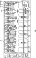
- an engine block 10 for an internal combustion engine (not illustrated).
- the engine is an internal combustion engine of any type, and can include a stoichiometric engine, a gasoline engine, alcohol engine (e.g. ethanol or methanol), or a natural gas engine.
- the engine block 10 includes and at least partially defines six cylinder bores 20a, 20b, 20c, 20d, 20e, and 20f, in an in-line arrangement.
- the number of cylinders may be any number, and the arrangement of cylinders may be any arrangement, and is not limited to the number and arrangement shown in Fig. 1 .
- Each of the cylinder bores 20a-20f is surrounded by a cylinder bore wall 22a-22f, respectively.
- Each of the cylinder bore walls 22a-22f includes a liner stop mechanism 24a-24f configured to locate a liner or sleeve (not illustrated) in the cylinder bores 20a-20f.
- the liner stop mechanism 24a-24f in the illustrated embodiment is a lip, ledge, flange, rim, projecting edge, ridge or other configuration in the cylinder bore wall 22a-22f.
- the liner stop mechanism 24a-24f can be configured differently to engage and retain the liner in the cylinder bores 20a-20f.
- the cylinder bore wall 22a-22f includes a mid-portion 26a-26f that spans between an upper end 28a-28f and a lower end 30a-30f.
- a cylindrical axis Y spans between the upper and lower ends 28a-28f and 30a-30f.
- the liner stop mechanism 24c is located in the mid-portion 26c of the cylinder bore wall 22c.
- the liner stop mechanism 24a-24f is located at or near either the upper end 28a-28f or the lower end 30a-30f of the cylinder bore wall 22a-22f.
- Each of the cylinder bores 20a-20f is configured to receive a cylinder liner (not illustrated) to define a combustion chamber.
- a piston (not shown) may be slidably disposed within each of the liners in the cylinder bores 20a-20f to reciprocate between a top-dead-center position and a bottom-dead-center position, and a cylinder head (not shown) may be associated with each of the cylinder bores 20a-20f.
- Each of the cylinder bores 20a-20f, its respective piston, and the cylinder head form a combustion chamber.
- engine block 10 includes six such combustion chambers.
- engine block 10 may include a greater or lesser number of cylinders and combustion chambers and that the cylinders and combustion chambers may be disposed in an "in-line” configuration, a "V" configuration, or in any other suitable configuration.
- Cylinder liners may be inserted into cylinder bores 20a-20f under a variety of conditions.
- One such condition is a press fit, also known as an interference fit or friction fit, for example, creates an axial hold where adjoining parts share the same space by creating a slight elastic deformation and a compression force between the adjoining parts. Compression from the press fit increases the friction between the adjoining parts to a point where independent movement of the adjoining parts is not possible under normal operating conditions.
- Press fits between the cylinder liner and engine block 10 may be created using physical presses, principles of thermal expansion or other suitable method.
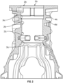
- the engine block 10 includes a first outer cylinder block wall 40 opposite a second outer cylinder block wall 42 with the cylinders bores 20a-20f between the first and second outer cylindrical block walls 40 and 42.
- Each of the first and second outer cylinder block walls 40 and 42 surround at least a portion of the cylinder bore walls 22a-22f.
- the first outer cylinder block wall 40 includes a first rib 46a positioned above the liner stop mechanism 24a and a second rib 48a positioned below the liner stop mechanism 24a relative to the cylindrical axis Y of the cylinder bore 20a.
- the first outer cylinder block wall 40 also includes a third rib 50a positioned above the liner stop mechanism 24 and a fourth rib 52a positioned below the liner stop mechanism 24a relative to the cylindrical axis Y of the cylinder bore 20a.
- a head boss 54a is positioned between the first and third ribs 46a and 50a and the second and fourth ribs 48a and 52a.
- the second outer cylinder block wall 42 also includes similar first and second ribs as described with respect to the first outer cylinder block wall 40 therefore for the sake of brevity these will not be described again.
- the first outer cylindrical block wall 40 includes additional first and second ribs similar to first and second ribs 46a and 48a for each of the remaining cylinder bores 20b-20f.
- the first outer cylindrical block wall 40 includes additional third and fourth ribs similar to third and fourth ribs 50a and 52a for each of the remaining cylinder bores 20b-20f.
- the additional first, second, third and fourth ribs will not be described for the sake of brevity.
- the first, second, third, and fourth ribs 46a, 48a, 50a, and 52a generally follow the circumference of cylinder bore 20a or the liner that would be installed therein.
- the first rib 46a is placed above the liner stop mechanism 24a and the second rib 48a is positioned below the liner stop mechanism 24a, with a space there between in the direction of the cylindrical axis Y.
- the first and second ribs 46a and 48a act to reduce rotation of a liner seat of a liner installed in the cylinder bore 20a and reduce the propensity of the liner to buckle under loads in the direction of a liner axis, or due to loads from cylinder pressure or thermal expansion.
- the first and second ribs 46a and 48a also act to reduce rotation or expansion of a liner wall of the liner, where the liner is in contact with the engine block 10 due to press-fit, or transitional fits which typically close under thermal or pressure related expansion.
- first rib 46a and the third rib 50a are positioned closer to the liner stop mechanism 24a than the second rib 48a and the fourth rib 52a as measured relative to the cylindrical axis Y.
- the second rib 48a and fourth rib 52a are positioned closer to the liner stop mechanism 24a than the first rib 46a and the third rib 50a as measured relative to the cylindrical axis Y.
- the first, second, third, and fourth ribs 46a, 48a, 50a, and 52a are positioned equidistant from the liner stop mechanism 24a as measured relative to the cylindrical axis Y.
- the first rib 46a has a first width W1 and the second rib 48a has a second width W2 wherein the first rib 46a and the second rib 48a extend in a direction of the cylindrical axis Y of the cylinder bore 20a.
- the first width W1 and the second width W2 are the same, in other forms they are different.
- the first rib 46a has a first height H1 and the second rib 48a has a second height H2 such that the first and the second ribs 46a and 48a extend in a direction perpendicular to the cylindrical axis Y of the cylinder bore 20a.
- the third rib 50a is similar to the first rib 46a
- the fourth rib 52a is similar to the second rib 48a.
- first, second, third, and fourth ribs 46a, 48a, 50a, and 52a of the first outer cylinder block wall 40 and the corresponding ribs on the second outer cylinder block wall 42 that surround or partially surround the wet cylinder liner in the cylinder bore 20a beneficially reduce deformation or distortion of the wet cylinder liner under installation and operating conditions.
- the first, second, third, and fourth ribs 46a, 48a, 50a, and 52a of the first outer cylinder block wall 40 and the corresponding ribs on the second outer cylinder block wall 42 also reduce engine oil consumption and can apply on top, mid or bottom stop liner configurations.
- first, second, third, and fourth ribs 46a, 48a, 50a, and 52a do not add too much weight or cost to manufacture.
- the first, second, third, and fourth ribs 46a, 48a, 50a, and 52a are also easy to manufacture for gray iron block casting.
Landscapes
- Engineering & Computer Science (AREA)
- Chemical & Material Sciences (AREA)
- Combustion & Propulsion (AREA)
- Mechanical Engineering (AREA)
- General Engineering & Computer Science (AREA)
- Cylinder Crankcases Of Internal Combustion Engines (AREA)
Claims (14)
- Motorblock (10) für einen Verbrennungsmotor, wobei der Motorblock (10) eine von einer Zylinderbohrungswand (22a-22f) umgebene Zylinderbohrung (20a-20f) aufweist, wobei die Zylinderbohrungswand einen Mittelabschnitt (26a-26f), der sich zwischen einem oberen Ende (28a-28f) und einem unteren Ende (30a-30f) der Zylinderbohrungswand erstreckt, aufweist, wobei der Mittelabschnitt einen Laufbuchsenanschlagmechanismus (24a-24f), der in einem Abstand von dem oberen Ende der Zylinderbohrungswand positioniert ist, enthält, wobei der Laufbuchsenanschlagmechanismus eine Laufbuchse in der Zylinderbohrung lokalisiert und stützt, wobei der Motorblock eine äußere Zylinderblockwand (40, 42), die mindestens einen Abschnitt der Zylinderbohrungswand umgibt, aufweist, wobei die äußere Zylinderblockwand eine erste Rippe (46a-46f), die über dem Laufbuchsenanschlagmechanismus positioniert ist, und eine zweite Rippe (48a-48f), die unter dem Laufbuchsenanschlagmechanismus relativ zu einer Zylinderachse der Zylinderbohrung positioniert ist, enthält, wobei die äußere Zylinderblockwand eine dritte Rippe (50a-50f), die über dem Laufbuchsenanschlagmechanismus positioniert ist, und eine vierte Rippe (52a-52f), die unter dem Laufbuchsenanschlagmechanismus positioniert ist, enthält, dadurch gekennzeichnet, dass die äußere Zylinderblockwand einen Kopfansatz (54a-54f), der zwischen der ersten und der dritten Rippe positioniert ist, enthält, wobei der Kopfansatz zwischen der zweiten und der vierten Rippe positioniert ist, wobei die erste und die dritte Rippe sich unter dem oberen Ende der Zylinderbohrungswand befinden und die zweite und die vierte Rippe sich über dem unteren Ende der Zylinderbohrungswand befinden.
- Vorrichtung nach Anspruch 1, wobei die erste Rippe näher als die zweite Rippe bei dem Laufbuchsenanschlagmechanismus positioniert ist.
- Vorrichtung nach Anspruch 1, wobei die zweite Rippe näher als die erste Rippe bei dem Laufbuchsenanschlagmechanismus positioniert ist.
- Vorrichtung nach Anspruch 1, wobei die erste Rippe und die zweite Rippe äquidistant von dem Laufbuchsenanschlagmechanismus positioniert sind.
- Vorrichtung nach Anspruch 1, wobei die erste Rippe eine erste Breite aufweist und die zweite Rippe eine zweite Breite aufweist, die Breiten der ersten und der zweiten Rippe in einer Richtung der Zylinderachse der Zylinderbohrung verlaufen und die erste Breite und die zweite Breite gleich sind; und
wobei die erste Rippe eine erste Höhe aufweist und die zweite Rippe eine zweite Höhe aufweist, die Höhen der ersten und der zweiten Rippe in einer zu der Zylinderachse der Zylinderbohrung senkrechten Richtung verlaufen. - Vorrichtung nach Anspruch 1, wobei sich der Laufbuchsenanschlagmechanismus in der Nähe des oberen Endes der Zylinderbohrungswand befindet.
- Vorrichtung nach Anspruch 1, wobei sich der Laufbuchsenanschlagmechanismus in dem Mittelabschnitt der Zylinderbohrungswand befindet.
- Vorrichtung nach Anspruch 1, wobei sich der Laufbuchsenanschlagmechanismus in der Nähe des unteren Endes der Zylinderbohrungswand befindet.
- Vorrichtung nach Anspruch 1, die ferner Folgendes umfasst:
eine in der Zylinderbohrung montierte Laufbuchse, wobei ein Abschnitt der Laufbuchse auf dem Laufbuchsenanschlagmechanismus in Eingriff genommen und gehalten wird. - Vorrichtung nach Anspruch 1, wobei die erste Rippe und die zweite Rippe so angeordnet sind, dass sie den Laufbuchsenanschlagmechanismus außerhalb der Zylinderbohrungswand beidseitig einfassen, wobei sich die erste Rippe auf der äußeren Zylinderblockwand unter dem oberen Ende der Zylinderbohrungswand befindet und sich die zweite Rippe auf der äußeren Zylinderblockwand über dem unteren Ende der Zylinderbohrungswand befindet.
- Vorrichtung nach Anspruch 10, wobei die erste Rippe näher als die zweite Rippe bei dem Laufbuchsenanschlagmechanismus positioniert ist; oderwobei die zweite Rippe näher als die erste Rippe bei dem Laufbuchsenanschlagmechanismus positioniert ist; oderwobei die erste Rippe und die zweite Rippe äquidistant von dem Laufbuchsenanschlagmechanismus positioniert sind.
- Vorrichtung nach Anspruch 10, wobei die erste Rippe eine erste Breite aufweist und die zweite Rippe eine zweite Breite aufweist, die Breiten der ersten und der zweiten Rippe in einer Richtung der Zylinderachse der Zylinderbohrung verlaufen und die erste Breite und die zweite Breite gleich sind; und
wobei die erste Rippe eine erste Höhe aufweist und die zweite Rippe eine zweite Höhe aufweist, die Höhen der ersten und der zweiten Rippe in einer zu der Zylinderachse der Zylinderbohrung senkrechten Richtung verlaufen. - Vorrichtung nach Anspruch 10, wobei die mindestens eine Zylinderbohrung eine Vielzahl von in einer Reihe angeordneten Zylinderbohrungen enthält, wobei jede der Zylinderbohrungen eine Menge aus der ersten und der zweiten Rippe aufweist, wobei eine erste Menge aus der ersten und der zweiten Rippe in Richtung einer benachbarten Menge aus der ersten und der zweiten Rippe verläuft.
- Vorrichtung nach Anspruch 10, die ferner Folgendes umfasst:
eine in der Zylinderbohrung montierte Laufbuchse, wobei der Laufbuchsenanschlagmechanismus in die Laufbuchse eingreift, um die Laufbuchse in der Zylinderbohrung zu halten.
Applications Claiming Priority (2)
| Application Number | Priority Date | Filing Date | Title |
|---|---|---|---|
| US201862781943P | 2018-12-19 | 2018-12-19 | |
| PCT/US2019/066271 WO2020131625A1 (en) | 2018-12-19 | 2019-12-13 | Unique block rib geometry for reducing liner distortion |
Publications (3)
| Publication Number | Publication Date |
|---|---|
| EP3864274A1 EP3864274A1 (de) | 2021-08-18 |
| EP3864274A4 EP3864274A4 (de) | 2022-07-06 |
| EP3864274B1 true EP3864274B1 (de) | 2025-05-07 |
Family
ID=71102276
Family Applications (1)
| Application Number | Title | Priority Date | Filing Date |
|---|---|---|---|
| EP19899832.0A Active EP3864274B1 (de) | 2018-12-19 | 2019-12-13 | Einzigartige blockrippengeometrie zur verminderung der auskleidungsverzerrung |
Country Status (4)
| Country | Link |
|---|---|
| US (2) | US11698042B2 (de) |
| EP (1) | EP3864274B1 (de) |
| CN (1) | CN113167190B (de) |
| WO (1) | WO2020131625A1 (de) |
Families Citing this family (4)
| Publication number | Priority date | Publication date | Assignee | Title |
|---|---|---|---|---|
| EP3864274B1 (de) | 2018-12-19 | 2025-05-07 | Cummins, Inc. | Einzigartige blockrippengeometrie zur verminderung der auskleidungsverzerrung |
| CN115726898A (zh) * | 2021-08-26 | 2023-03-03 | 康明斯公司 | 气缸体上的肋结构 |
| USD1107757S1 (en) * | 2024-10-16 | 2025-12-30 | Speedway Motors, Inc. | Mock engine block |
| USD1111055S1 (en) * | 2024-10-16 | 2026-02-03 | Speedway Motors, Inc. | Mock engine block |
Family Cites Families (29)
| Publication number | Priority date | Publication date | Assignee | Title |
|---|---|---|---|---|
| US3568573A (en) * | 1969-06-25 | 1971-03-09 | Caterpillar Tractor Co | Cylinder liner support |
| US3977385A (en) | 1973-06-21 | 1976-08-31 | National Research Development Corporation | Internal combustion engines with straight line reinforcing members between cylinder heads and main bearings |
| US4016850A (en) * | 1974-02-22 | 1977-04-12 | Brunswick Corporation | Ported cylinder construction for a two-cycle engine |
| US4244330A (en) | 1978-11-13 | 1981-01-13 | Cummins Engine Company, Inc. | Engine cylinder liner having a mid stop |
| US4440118A (en) | 1980-05-13 | 1984-04-03 | Cummins Engine Company, Inc. | Oil cooled internal combustion engine |
| DE3326320C2 (de) * | 1983-07-21 | 1990-10-04 | Dr.Ing.H.C. F. Porsche Ag, 7000 Stuttgart | Kolbenbrennkraftmaschine mit einer, in ein Zylinderkurbelgehäuse eingesetzten, nassen Zylinderlaufbüchse |
| SE470055B (sv) * | 1991-03-05 | 1993-11-01 | Volvo Ab | Sätt och verktyg för pressgjutning |
| EP0751289B1 (de) * | 1992-01-06 | 1999-04-14 | Honda Giken Kogyo Kabushiki Kaisha | Gussverfahren eines Zylinderblockes |
| KR100285438B1 (ko) | 1993-11-01 | 2001-04-02 | 정몽규 | 내연기관 |
| DE9319055U1 (de) | 1993-12-11 | 1995-04-13 | FEV Motorentechnik GmbH & Co. KG, 52078 Aachen | Kolbenmaschine, insbesondere Kolbenbrennkraftmaschine mit versteiftem Motorblock mittels unterbrochener Rippen |
| DE4436969C2 (de) * | 1994-10-15 | 1996-08-22 | Hatz Motoren | Zylinderlaufbüchse |
| DE19511864C1 (de) | 1995-03-31 | 1996-07-25 | Daimler Benz Ag | Brennkraftmaschine |
| US5979374A (en) | 1998-06-12 | 1999-11-09 | Cummins Engine Company, Inc. | Control cooled cylinder liner |
| US6044821A (en) | 1998-11-19 | 2000-04-04 | Cummins Engine Company, Inc. | Durable cylinder liner and method of making the liner |
| DE10112132A1 (de) | 2001-03-14 | 2002-09-19 | Bayerische Motoren Werke Ag | Zylinderkurbelgehäuse für eine flüssigkeitsgekühlte Brennkraftmaschine |
| US20040244758A1 (en) * | 2003-06-06 | 2004-12-09 | Cummins Inc. | Method for increasing the displacement of an internal combustion engine and engine having increased displacement thereby |
| JP2005155600A (ja) * | 2003-10-31 | 2005-06-16 | Toyota Motor Corp | 水冷式エンジン及びそのシリンダブロック |
| JP2005201084A (ja) * | 2004-01-13 | 2005-07-28 | Toyota Motor Corp | シリンダブロック |
| JP2006002602A (ja) | 2004-06-16 | 2006-01-05 | Nissan Motor Co Ltd | 内燃機関のシリンダブロック |
| JP4367288B2 (ja) * | 2004-08-17 | 2009-11-18 | トヨタ自動車株式会社 | エンジンのシリンダブロック |
| DE102005048537A1 (de) * | 2005-10-11 | 2007-04-19 | Daimlerchrysler Ag | Brennkraftmaschine mit einem Zylinderkopf und einem Zylindergehäuse |
| JP4532430B2 (ja) | 2006-03-31 | 2010-08-25 | 富士重工業株式会社 | エンジンのクランクケース |
| JP2010138779A (ja) * | 2008-12-11 | 2010-06-24 | Mitsubishi Heavy Ind Ltd | クランクケースの構造 |
| US8408178B2 (en) | 2009-08-04 | 2013-04-02 | International Engine Intellectual Property Company, Llc | Engine crankcase firing deck having anti-distortion projections |
| DE102012006852A1 (de) * | 2012-04-04 | 2013-10-10 | Andreas Stihl Ag & Co. Kg | Verbrennungsmotor |
| CN104813013B (zh) | 2012-11-30 | 2017-11-24 | 康明斯知识产权公司 | 发动机汽缸和衬垫组件 |
| US10107228B2 (en) * | 2015-03-31 | 2018-10-23 | Cummins Inc. | Internal combustion engine cylinder liner flange with non-circular profile |
| US9856817B2 (en) | 2015-03-31 | 2018-01-02 | Harley-Davidson Motor Company Group, LLC | Bolt-on cylinder kit and method for increasing the displacement of an engine |
| EP3864274B1 (de) | 2018-12-19 | 2025-05-07 | Cummins, Inc. | Einzigartige blockrippengeometrie zur verminderung der auskleidungsverzerrung |
-
2019
- 2019-12-13 EP EP19899832.0A patent/EP3864274B1/de active Active
- 2019-12-13 CN CN201980076496.1A patent/CN113167190B/zh active Active
- 2019-12-13 WO PCT/US2019/066271 patent/WO2020131625A1/en not_active Ceased
-
2021
- 2021-06-18 US US17/351,438 patent/US11698042B2/en active Active
- 2021-06-18 US US17/351,639 patent/US11536222B2/en active Active
Also Published As
| Publication number | Publication date |
|---|---|
| CN113167190B (zh) | 2024-07-30 |
| US20210310439A1 (en) | 2021-10-07 |
| EP3864274A4 (de) | 2022-07-06 |
| EP3864274A1 (de) | 2021-08-18 |
| CN113167190A (zh) | 2021-07-23 |
| WO2020131625A1 (en) | 2020-06-25 |
| US11698042B2 (en) | 2023-07-11 |
| US20210324816A1 (en) | 2021-10-21 |
| US11536222B2 (en) | 2022-12-27 |
Similar Documents
| Publication | Publication Date | Title |
|---|---|---|
| EP3864274B1 (de) | Einzigartige blockrippengeometrie zur verminderung der auskleidungsverzerrung | |
| EP4077901B1 (de) | Profilierte zylinderbüchse für eine bohrungsverzugskontrolle | |
| US10309535B2 (en) | Piston ring for an internal combustion engine | |
| US7975601B2 (en) | Engine cylinder liner | |
| US6196179B1 (en) | Internal combustion engine | |
| CN112969874A (zh) | 内燃发动机的活塞和汽缸 | |
| EP2815155B1 (de) | Kolbenring für verbrennungsmotor | |
| JP6337058B2 (ja) | クロスヘッド型ターボ過給式大型2ストローク圧縮着火内燃機関のためのトップピストンリング | |
| US9057341B2 (en) | Engine cylinder mid-stop | |
| US7293497B2 (en) | Piston | |
| CN113090407B (zh) | 气缸体负荷路径几何结构 | |
| EP1943444B2 (de) | Kolben | |
| US20170299056A1 (en) | Oil Ring for a Piston Assembly | |
| US20050028779A1 (en) | Piston for an internal combustion engine | |
| US20200284344A1 (en) | Piston ring with inlaid dlc coating and method of manufacturing | |
| WO2004109083A1 (en) | Gas seal for an internal combustion engine | |
| EP2216534A1 (de) | Verfahren zum Ausbüchsen eines Zylinders und entsprechende Zylinderbüchse | |
| KR20190106737A (ko) | 내연 기관의 피스톤 조립체 | |
| JP2009257478A (ja) | 内燃機関のピストンリング構造 | |
| US20130213221A1 (en) | Piston ring for an internal combustion engine |
Legal Events
| Date | Code | Title | Description |
|---|---|---|---|
| STAA | Information on the status of an ep patent application or granted ep patent |
Free format text: STATUS: THE INTERNATIONAL PUBLICATION HAS BEEN MADE |
|
| PUAI | Public reference made under article 153(3) epc to a published international application that has entered the european phase |
Free format text: ORIGINAL CODE: 0009012 |
|
| STAA | Information on the status of an ep patent application or granted ep patent |
Free format text: STATUS: REQUEST FOR EXAMINATION WAS MADE |
|
| 17P | Request for examination filed |
Effective date: 20210513 |
|
| AK | Designated contracting states |
Kind code of ref document: A1 Designated state(s): AL AT BE BG CH CY CZ DE DK EE ES FI FR GB GR HR HU IE IS IT LI LT LU LV MC MK MT NL NO PL PT RO RS SE SI SK SM TR |
|
| RIN1 | Information on inventor provided before grant (corrected) |
Inventor name: ZHOU, XILING Inventor name: KUMARESHAN, VIJAYSAI KARUPPIAH Inventor name: PURCELL III, JOHN JERL Inventor name: CLARK, MATHEW A. |
|
| DAV | Request for validation of the european patent (deleted) | ||
| DAX | Request for extension of the european patent (deleted) | ||
| A4 | Supplementary search report drawn up and despatched |
Effective date: 20220603 |
|
| RIC1 | Information provided on ipc code assigned before grant |
Ipc: F02F 1/16 20060101ALI20220530BHEP Ipc: F02F 1/08 20060101ALI20220530BHEP Ipc: F02F 1/00 20060101AFI20220530BHEP |
|
| P01 | Opt-out of the competence of the unified patent court (upc) registered |
Effective date: 20230510 |
|
| GRAP | Despatch of communication of intention to grant a patent |
Free format text: ORIGINAL CODE: EPIDOSNIGR1 |
|
| STAA | Information on the status of an ep patent application or granted ep patent |
Free format text: STATUS: GRANT OF PATENT IS INTENDED |
|
| INTG | Intention to grant announced |
Effective date: 20241210 |
|
| GRAS | Grant fee paid |
Free format text: ORIGINAL CODE: EPIDOSNIGR3 |
|
| GRAA | (expected) grant |
Free format text: ORIGINAL CODE: 0009210 |
|
| STAA | Information on the status of an ep patent application or granted ep patent |
Free format text: STATUS: THE PATENT HAS BEEN GRANTED |
|
| AK | Designated contracting states |
Kind code of ref document: B1 Designated state(s): AL AT BE BG CH CY CZ DE DK EE ES FI FR GB GR HR HU IE IS IT LI LT LU LV MC MK MT NL NO PL PT RO RS SE SI SK SM TR |
|
| REG | Reference to a national code |
Ref country code: GB Ref legal event code: FG4D |
|
| REG | Reference to a national code |
Ref country code: CH Ref legal event code: EP |
|
| REG | Reference to a national code |
Ref country code: DE Ref legal event code: R096 Ref document number: 602019069799 Country of ref document: DE |
|
| REG | Reference to a national code |
Ref country code: IE Ref legal event code: FG4D |
|
| REG | Reference to a national code |
Ref country code: NL Ref legal event code: MP Effective date: 20250507 |
|
| PG25 | Lapsed in a contracting state [announced via postgrant information from national office to epo] |
Ref country code: PT Free format text: LAPSE BECAUSE OF FAILURE TO SUBMIT A TRANSLATION OF THE DESCRIPTION OR TO PAY THE FEE WITHIN THE PRESCRIBED TIME-LIMIT Effective date: 20250908 Ref country code: ES Free format text: LAPSE BECAUSE OF FAILURE TO SUBMIT A TRANSLATION OF THE DESCRIPTION OR TO PAY THE FEE WITHIN THE PRESCRIBED TIME-LIMIT Effective date: 20250507 Ref country code: FI Free format text: LAPSE BECAUSE OF FAILURE TO SUBMIT A TRANSLATION OF THE DESCRIPTION OR TO PAY THE FEE WITHIN THE PRESCRIBED TIME-LIMIT Effective date: 20250507 |
|
| REG | Reference to a national code |
Ref country code: LT Ref legal event code: MG9D |
|
| PG25 | Lapsed in a contracting state [announced via postgrant information from national office to epo] |
Ref country code: NO Free format text: LAPSE BECAUSE OF FAILURE TO SUBMIT A TRANSLATION OF THE DESCRIPTION OR TO PAY THE FEE WITHIN THE PRESCRIBED TIME-LIMIT Effective date: 20250807 Ref country code: GR Free format text: LAPSE BECAUSE OF FAILURE TO SUBMIT A TRANSLATION OF THE DESCRIPTION OR TO PAY THE FEE WITHIN THE PRESCRIBED TIME-LIMIT Effective date: 20250808 |
|
| PG25 | Lapsed in a contracting state [announced via postgrant information from national office to epo] |
Ref country code: PL Free format text: LAPSE BECAUSE OF FAILURE TO SUBMIT A TRANSLATION OF THE DESCRIPTION OR TO PAY THE FEE WITHIN THE PRESCRIBED TIME-LIMIT Effective date: 20250507 Ref country code: NL Free format text: LAPSE BECAUSE OF FAILURE TO SUBMIT A TRANSLATION OF THE DESCRIPTION OR TO PAY THE FEE WITHIN THE PRESCRIBED TIME-LIMIT Effective date: 20250507 |
|
| REG | Reference to a national code |
Ref country code: AT Ref legal event code: MK05 Ref document number: 1792695 Country of ref document: AT Kind code of ref document: T Effective date: 20250507 |
|
| PG25 | Lapsed in a contracting state [announced via postgrant information from national office to epo] |
Ref country code: BG Free format text: LAPSE BECAUSE OF FAILURE TO SUBMIT A TRANSLATION OF THE DESCRIPTION OR TO PAY THE FEE WITHIN THE PRESCRIBED TIME-LIMIT Effective date: 20250507 |
|
| PG25 | Lapsed in a contracting state [announced via postgrant information from national office to epo] |
Ref country code: HR Free format text: LAPSE BECAUSE OF FAILURE TO SUBMIT A TRANSLATION OF THE DESCRIPTION OR TO PAY THE FEE WITHIN THE PRESCRIBED TIME-LIMIT Effective date: 20250507 |
|
| PG25 | Lapsed in a contracting state [announced via postgrant information from national office to epo] |
Ref country code: AT Free format text: LAPSE BECAUSE OF FAILURE TO SUBMIT A TRANSLATION OF THE DESCRIPTION OR TO PAY THE FEE WITHIN THE PRESCRIBED TIME-LIMIT Effective date: 20250507 |
|
| PG25 | Lapsed in a contracting state [announced via postgrant information from national office to epo] |
Ref country code: RS Free format text: LAPSE BECAUSE OF FAILURE TO SUBMIT A TRANSLATION OF THE DESCRIPTION OR TO PAY THE FEE WITHIN THE PRESCRIBED TIME-LIMIT Effective date: 20250807 |
|
| PG25 | Lapsed in a contracting state [announced via postgrant information from national office to epo] |
Ref country code: IS Free format text: LAPSE BECAUSE OF FAILURE TO SUBMIT A TRANSLATION OF THE DESCRIPTION OR TO PAY THE FEE WITHIN THE PRESCRIBED TIME-LIMIT Effective date: 20250907 |
|
| PG25 | Lapsed in a contracting state [announced via postgrant information from national office to epo] |
Ref country code: LV Free format text: LAPSE BECAUSE OF FAILURE TO SUBMIT A TRANSLATION OF THE DESCRIPTION OR TO PAY THE FEE WITHIN THE PRESCRIBED TIME-LIMIT Effective date: 20250507 |
|
| PGFP | Annual fee paid to national office [announced via postgrant information from national office to epo] |
Ref country code: GB Payment date: 20251229 Year of fee payment: 7 |
|
| PG25 | Lapsed in a contracting state [announced via postgrant information from national office to epo] |
Ref country code: SM Free format text: LAPSE BECAUSE OF FAILURE TO SUBMIT A TRANSLATION OF THE DESCRIPTION OR TO PAY THE FEE WITHIN THE PRESCRIBED TIME-LIMIT Effective date: 20250507 Ref country code: DK Free format text: LAPSE BECAUSE OF FAILURE TO SUBMIT A TRANSLATION OF THE DESCRIPTION OR TO PAY THE FEE WITHIN THE PRESCRIBED TIME-LIMIT Effective date: 20250507 |
|
| PG25 | Lapsed in a contracting state [announced via postgrant information from national office to epo] |
Ref country code: CZ Free format text: LAPSE BECAUSE OF FAILURE TO SUBMIT A TRANSLATION OF THE DESCRIPTION OR TO PAY THE FEE WITHIN THE PRESCRIBED TIME-LIMIT Effective date: 20250507 |
|
| PG25 | Lapsed in a contracting state [announced via postgrant information from national office to epo] |
Ref country code: EE Free format text: LAPSE BECAUSE OF FAILURE TO SUBMIT A TRANSLATION OF THE DESCRIPTION OR TO PAY THE FEE WITHIN THE PRESCRIBED TIME-LIMIT Effective date: 20250507 |
|
| PG25 | Lapsed in a contracting state [announced via postgrant information from national office to epo] |
Ref country code: RO Free format text: LAPSE BECAUSE OF FAILURE TO SUBMIT A TRANSLATION OF THE DESCRIPTION OR TO PAY THE FEE WITHIN THE PRESCRIBED TIME-LIMIT Effective date: 20250507 Ref country code: SK Free format text: LAPSE BECAUSE OF FAILURE TO SUBMIT A TRANSLATION OF THE DESCRIPTION OR TO PAY THE FEE WITHIN THE PRESCRIBED TIME-LIMIT Effective date: 20250507 |
|
| PG25 | Lapsed in a contracting state [announced via postgrant information from national office to epo] |
Ref country code: IT Free format text: LAPSE BECAUSE OF FAILURE TO SUBMIT A TRANSLATION OF THE DESCRIPTION OR TO PAY THE FEE WITHIN THE PRESCRIBED TIME-LIMIT Effective date: 20250507 |
|
| REG | Reference to a national code |
Ref country code: DE Ref legal event code: R097 Ref document number: 602019069799 Country of ref document: DE |
|
| PLBE | No opposition filed within time limit |
Free format text: ORIGINAL CODE: 0009261 |
|
| STAA | Information on the status of an ep patent application or granted ep patent |
Free format text: STATUS: NO OPPOSITION FILED WITHIN TIME LIMIT |
|
| REG | Reference to a national code |
Ref country code: CH Ref legal event code: L10 Free format text: ST27 STATUS EVENT CODE: U-0-0-L10-L00 (AS PROVIDED BY THE NATIONAL OFFICE) Effective date: 20260318 |