EP3860880B1 - Einstellbarer montagemechanismus für eine rückspiegelanordnung - Google Patents
Einstellbarer montagemechanismus für eine rückspiegelanordnung Download PDFInfo
- Publication number
- EP3860880B1 EP3860880B1 EP19868933.3A EP19868933A EP3860880B1 EP 3860880 B1 EP3860880 B1 EP 3860880B1 EP 19868933 A EP19868933 A EP 19868933A EP 3860880 B1 EP3860880 B1 EP 3860880B1
- Authority
- EP
- European Patent Office
- Prior art keywords
- rearview assembly
- mount
- connector
- operably coupled
- housing
- Prior art date
- Legal status (The legal status is an assumption and is not a legal conclusion. Google has not performed a legal analysis and makes no representation as to the accuracy of the status listed.)
- Active
Links
Images


Classifications
-
- B—PERFORMING OPERATIONS; TRANSPORTING
- B60—VEHICLES IN GENERAL
- B60R—VEHICLES, VEHICLE FITTINGS, OR VEHICLE PARTS, NOT OTHERWISE PROVIDED FOR
- B60R1/00—Optical viewing arrangements; Real-time viewing arrangements for drivers or passengers using optical image capturing systems, e.g. cameras or video systems specially adapted for use in or on vehicles
- B60R1/02—Rear-view mirror arrangements
- B60R1/04—Rear-view mirror arrangements mounted inside vehicle
Definitions
- the present disclosure generally relates to a mount for a rearview assembly, and more particularly to an adjustable mounting mechanism for a rearview assembly.
- WO 2010/111173 describes an interior rearview mirror assembly according to the preamble of claim 1 including a mirror casing, a reflective element and a mounting assembly for adjustably mounting the mirror assembly at an interior portion of a vehicle.
- a rearview assembly includes a housing.
- a connector is configured to be secured to a button inside a vehicle.
- the connector includes a mount connecting feature with a plurality of distinct connection locations.
- a mount includes a proximal end operably coupled with the housing and a distal end including a location feature configured to engage one of the plurality of distinct connection locations.
- the location feature includes forward flanges and rearward flanges disposed within the mount.
- the forward flanges and rearward flanges of the location feature intersect a cylindrical boss that extends into a receiving socket defined in the connector.
- the present illustrated embodiments reside primarily in combinations of method steps and apparatus components related to a an adjustable mounting mechanism for a rearview assembly. Accordingly, the apparatus components and method steps have been represented, where appropriate, by conventional symbols in the drawings, showing only those specific details that are pertinent to understanding the embodiments of the present disclosure so as not to obscure the disclosure with details that will be readily apparent to those of ordinary skill in the art having the benefit of the description herein. Further, like numerals in the description and drawings represent like elements.
- the terms “upper,” “lower,” “right,” “left,” “rear,” “front,” “vertical,” “horizontal,” and derivatives thereof, shall relate to the disclosure as oriented in FIG. 1 .
- the term “front” shall refer to the surface of the device closer to an intended viewer of the device, and the term “rear” shall refer to the surface of the device further from the intended viewer of the device.
- the disclosure may assume various alternative orientations, except where expressly specified to the contrary.
- the specific devices and processes illustrated in the attached drawings, and described in the following specification are simply exemplary embodiments of the inventive concepts defined in the appended claims. Hence, specific dimensions and other physical characteristics relating to the embodiments disclosed herein are not to be considered as limiting, unless the claims expressly state otherwise.
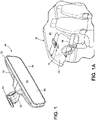
- reference numeral 10 generally designates a rearview assembly including a housing 12.
- a connector 14 is configured to be secured to a button 16 inside a vehicle 18.
- the connector 14 includes a mount connecting feature 20 with a plurality of distinct connection locations 22a, 22b, 22c.
- the plurality of distinct connection locations 22a, 22b, 22c of the connector 14 may include spaced ribs 23a, 23b configured to engage a location feature 30.
- a mount 24 includes a proximal end 26 operably coupled with the housing 12 and a distal end 28 including the location feature 30 that is configured to engage one of the plurality of distinct connection locations 22a, 22b, 22c.
- the mount 24 may include a wire passageway 40 configured to house a wire harness that may be operably coupled with a circuit board disposed in the housing 12.
- the circuit board may be operably coupled with a display 60 and an electro-optic element.
- the rearview assembly 10 of the present disclosure is generally configured for use in the vehicle 18.
- the button 16 may be operably coupled with a windshield 42 or headliner 44 of the vehicle 18.
- the button 16, and ultimately the connector 14 may be operably coupled with another portion of the vehicle 18, including the dash 46.
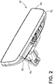
- the rearview assembly 10 includes a glass surface 48 configured to provide a rearward view of the vehicle 18 to a driver. It will be understood that the rearward view may be generated by a reflection of a rearward portion of the vehicle 18 provided by an at least reflective surface of the rearview assembly 10. The reflection is then observed by the driver. Alternatively, the rearward view may be generated by the display 60 disposed within the rearview assembly 10.
- an imager disposed inside or outside of the vehicle 18 captures image data and relays the image data to the display 60, which is then shown to the driver.
- the display 60 may be similar to that described in U.S. Patent No. 8,879,139 . It will be understood that the rearview assembly 10 may include both a reflective surface and the display 60
- the rearview assembly 10 may include a wide variety of functionality, including the use of an electro-optic assembly 70, which may include an electrochromic device that is configured to darken during certain lighting conditions.
- the glass surface 48 may be part of an electro-optic element or on a prism-type construction.
- the prism-type construction may generally include one glass surface 48 having a varying thickness from top to bottom.
- the glass surface 48 includes at least two glass substrates.
- the glass surface 48 includes the front substrate as well as a rear substrate.
- an electro-optic element is an electrochromic medium, which includes at least one solvent, at least one anodic material, and at least one cathodic material.
- both of the anodic and cathodic materials are electroactive and at least one of them is electrochromic.
- electrochromic will be defined herein as a material that undergoes a modification in its oxidation state upon exposure to a particular electrical potential difference.
- electrochromic will be defined herein, regardless of its ordinary meaning, as a material that exhibits a change in its extinction coefficient at one or more wavelengths upon exposure to a particular electrical potential difference.
- Electrochromic components include materials whose color or opacity are affected by electric current, such that when an electrical current is applied to the material, the color or opacity change from a first phase to a second phase.
- the electrochromic component as disclosed herein may be a single-layer, single-phase component, multi-layer component, or multi-phase component, as described in U.S. Patent Nos. 5,928,572 entitled “Electrochromic Layer And Devices Comprising Same,” 5,998,617 entitled “Electrochromic Compounds," 6,020,987 entitled “Electrochromic Medium Capable Of Producing A Pre-selected Color,” 6,037,471 entitled “Electrochromic Compounds," 6,141,137 entitled “Electrochromic Media For Producing A Pre-selected Color," 6,241,916 entitled “Electrochromic System,” 6,193,912 entitled “Near Infrared-Absorbing Electrochromic Compounds And Devices Comprising Same,” 6,249,369 entitled “Coupled Electrochromic Compounds With Photostable Dication Oxidation States,” and 6,137,620 entitled “Electrochromic Media With Concentration Enhanced Stability, Process For The Preparation Thereof and Use In Electrochromic Devices"; U.
- the glass surface 48 may also be any other element having partially reflective, partially transmissive properties. To provide electric current to the glass surface 48, electrical elements are provided on opposing sides of the element, to generate an electrical potential therebetween. A J-clip is electrically engaged with each electrical element, and element wires extend from the J-clips to a primary printed circuit board (PCB).
- PCB primary printed circuit board
- the electro-optic assembly 70 may darken, thus minimizing the glare observed by the driver.
- the rearview assembly 10 may also include other features, including a temperature gauge, compass, rain sensor, etc.
- the glass surface 48 is surrounded by a bezel 72 that operably couples the electro-optic assembly 70 to the housing 12.
- the bezel 72 extends about the electro-optic assembly 70.
- the rearview assembly 10 may be a bezel-less construction wherein the electro-optic assembly 70 interfaces directly with the rear housing 12. As illustrated, the mount 24 of the rearview assembly 10 is configured to engage the connector 14.
- the connector 14, engages the button 16.
- the button 16 slidably receives the connector 14.
- the proximal end 26 of the mount 24 includes a pivot connection, which may include a pivot ball 80 configured to allow rotation of the housing 12 relative to the mount 24.
- a wiring aperture may extend through the pivot ball 80.
- the housing 12 can be moved to an angle between 10 degrees and 60 degrees relative to the windshield 42.
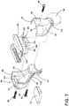
- the distal end 28 of the mount 24 is configured to engage an engagement portion 82 of the connector 14.
- the mount 24 may include a first half 84 that is operably coupled with a second half 86, which are mirror images or nearly mirror images of one another and which can be secured about the engagement portion 82 of the connector 14.
- the first and second halves 84, 86 of the mount 24 may be secured via mechanical fasteners 90 to one another and the engagement portion 82 of the connector 14. It is also contemplated that other manners of connecting the first and second halves 84, 86 of the connector 14 may be used. Upon selection of the desired angle of the mount 24 relative to the connector 14, the first and second halves 84, 86 can then be connected around the engagement portion 82 of the connector 14. As illustrated, the location feature 30 includes forward flanges 92, 93 and rearward flanges 94, 95 disposed within the mount 24. The first and second halves 84, 86 also include hubs 96, 97, respectively.
- the hub 96 is disposed between the forward flange 92 and the rearward flange 94 in the first half 84 ( FIG. 6 ).
- the hub 97 is disposed between the forward flange 93 and the rearward flange 95 in the second half 86 ( FIG. 7 ).
- the location feature 30 of the first and second halves 84, 86 is positioned in one of the plurality of distinct connection locations, including uppermost, intermediate, and lowermost connection locations 22a, 22b, 22c, respectively, based on the desired angle of the mount 24 relative to the connector 14 and the general slope of the windshield 42 of the vehicle 18 (see FIGS. 9A-9C ). More specifically, the forward flanges 92, 93 of the mount 24 are positioned within a preferred connection location 22a, 22b, 22c.
- the connection locations 22a, 22b, 22c are generally slots defined in the engagement portion 82 by ribs 23a, 23b.
- an upper rib 23a extends between the uppermost and intermediate connection locations 22a, 22b and a lower rib 23b is disposed between the intermediate and lowermost connection locations 22b, 22c.
- the hub 96 which also generally defines a cylindrical boss of the first half 84 is aligned with and engages a cylindrical recess 102 that generally defines a receiving socket set and which is disposed in the engagement portion 82 of the connector 14 ( FIG. 7 ).
- the hub 97 which generally defines a cylindrical boss of the second half 86 is aligned with and engages a cylindrical recess 106 that generally defines a receiving socket and which is disposed in the engagement portion 82 of the connector 14 ( FIG.
- Each cylindrical recess 102, 106 includes a fastener receiver.
- Both the hub 96 and the hub 97 are internal hubs and are not generally visible when the first and second halves 84, 86 are connected.
- the rearward flanges 94, 95 of the mount 24 are positioned within apertures 108, 109 of the connector 14, respectively.
- the mechanical fasteners 90 extend at least partially into or through the cylindrical hubs 96, 97 and into secure engagement with the engagement portion 82 of the connector 14.
- Another mechanical fastener 90 extends through the connector 14 at lower bosses 110, 112 adjacent to the pivot ball 80 of the mount 24.
- the mount 24 is configured for engagement with the connector 14 at a variety of angles which may extend between 20 degrees and 40 degrees, although even larger angle changes (e.g., 10 degrees to 60 degrees, for example, is contemplated).
- the desired angle of the connector 14 with the mount 24 may be governed by the angle at which the button 16 is connected with the interior of the vehicle 18. For example, if the windshield 42 of the vehicle 18 is angled downward to an angle between 30 degrees and 40 degrees relative to a horizontal plane, the connector 14 may be engaged with the mount 24 at a 20 degree down location ( FIG. 9A ). This corresponds to the uppermost connection location 22a. Accordingly, that is where the location feature 30 is positioned ( FIGS. 7 and 8 ).
- the angle between the connector 14 and the mount 24 may be adjusted to a 30 degree location ( FIG. 9B ). This corresponds to the intermediate connection location 22b. Accordingly, that is where the location feature 30 is positioned.
- the angle between the connector 14 and the mount 24 may be adjusted to the 40 degree location ( FIG. 9C ). This corresponds to the lowermost connection location 22c. Accordingly, that is where the location feature 30 is positioned.
- the versatility in angle that is provided in this disclosure helps arrange various rearview assemblies at various angles within a vehicle compensating for different windshield angles.
- a single ball mount construction is shown, a dual ball mount could also be provided.
- this system has improved vibration performance.
- this mounting construction can be used from base model rearview assemblies through high end full display mirror assemblies.
- the ribs that define the plurality of connection locations may act to dissipate energy during head impact in the event of a collision.
- the ribs may controllably deform or rupture during head impact of a predetermined force.
- the term "coupled” in all of its forms, couple, coupling, coupled, etc. generally means the joining of two components (electrical or mechanical) directly or indirectly to one another. Such joining may be stationary in nature or movable in nature. Such joining may be achieved with the two components (electrical or mechanical) and any additional intermediate members being integrally formed as a single unitary body with one another or with the two components. Such joining may be permanent in nature or may be removable or releasable in nature unless otherwise stated.
- elements shown as integrally formed may be constructed of multiple parts, or elements shown as multiple parts may be integrally formed, the operation of the interfaces may be reversed or otherwise varied, the length or width of the structures and/or members or connector or other elements of the system may be varied, the nature or number of adjustment positions provided between the elements may be varied.
- the elements and/or assemblies of the system may be constructed from any of a wide variety of materials that provide sufficient strength or durability, in any of a wide variety of colors, textures, and combinations.
Landscapes
- Engineering & Computer Science (AREA)
- Multimedia (AREA)
- Mechanical Engineering (AREA)
- Fittings On The Vehicle Exterior For Carrying Loads, And Devices For Holding Or Mounting Articles (AREA)
- Rear-View Mirror Devices That Are Mounted On The Exterior Of The Vehicle (AREA)
Claims (9)
- Eine Rückblickanordnung (10), die Folgendes umfasst:ein Gehäuse (12);einen Verbinder (14), der konfiguriert ist, um an einem Knopf (button) (16) innerhalb eines Fahrzeugs (18) befestigt zu werden, wobei der Verbinder (14) ein Halterungs-Verbindungsmerkmal (20) mit einer Vielzahl von individuellen Verbindungsstellen (22a, 22b, 22c) beinhaltet; undeine Halterung (24), die Folgendes beinhaltet: ein proximales Ende, das mit dem Gehäuse (12) wirkverbunden ist, und ein distales Ende (28), das ein Positionierungsmerkmal (30) enthält, das konfiguriert ist, um mit einer von der Vielzahl von individuellen Verbindungsstellen (22a, 22b, 22c) in Eingriff zu kommen;wobeidas Positionierungsmerkmal (30) vordere Flansche (92, 93) und hintere Flansche (94, 95) beinhaltet, die innerhalb der Halterung (24) angeordnet sind;die Rückblickanordnung (10) dadurch gekennzeichnet ist, dass: |die vorderen Flansche (92, 93) und die hinteren Flansche (94, 95) des Positionierungsmerkmals eine zylindrische Nabe (96, 97) schneiden, die sich in eine im Verbinder (14) definierte Aufnahmebuchse (102, 106) hinein erstreckt.
- Die Rückblickanordnung (10) nach Anspruch 1, wobei die Vielzahl von individuellen Verbindungsstellen (22a, 22b, 22c) des Halterungs-Verbindungsmerkmals (20) beabstandete Rippen (23a, 23b) beinhaltet, die so konfiguriert sind, dass sie in Flansche des Positionierungsmerkmals (30) eingreifen.
- Die Rückblickanordnung (10) nach einem der Ansprüche 1 oder 2, wobei das Gehäuse (12) in einem Winkel zwischen 10 Grad und 60 Grad relativ zu einer Windschutzscheibe (42) bewegt werden kann.
- Die Rückblickanordnung (10) nach irgendeinem der Ansprüche von 1 bis 3, wobei die Halterung (24) zwei Hälften (84, 86) beinhaltet, die um den Verbinder (14) herum wirkverbunden sind.
- Die Rückblickanordnung (10) nach irgendeinem der Ansprüche von 1 bis 4, wobei die Halterung (24) einen Kabeldurchgang (40) definiert, der so konfiguriert ist, dass er einen Kabelbaum aufnimmt, der mit einer im Gehäuse (12) angeordneten Leiterplatte wirkverbunden ist.
- Die Rückblickanordnung (10) nach Anspruch 5, wobei die Leiterplatte mit einer Anzeige (60) und einem elektrooptischen Element wirkverbunden ist.
- Die Rückblickanordnung (10) nach irgendeinem der Ansprüche von 1 bis 6, wobei die Vielzahl von individuellen Verbindungsstellen (22a, 22b, 22c) Schlitze bzw. Nuten (slots) definieren, die in der Aufnahmebuchse zusammenlaufen.
- Die Rückblickanordnung (10) nach Anspruch 7, wobei die Aufnahmebuchse eine Verschluss-Aufnahme (fastener receiver) beinhaltet.
- Die Rückblickanordnung (10) nach irgendeinem der Ansprüche von 1 bis 8, wobei der Verbinder (14) so konfiguriert ist, dass er den mit der Windschutzscheibe (42) des Fahrzeugs (18) wirkverbundenen Knopf (16) gleitend aufnimmt.
Applications Claiming Priority (2)
| Application Number | Priority Date | Filing Date | Title |
|---|---|---|---|
| US201862739981P | 2018-10-02 | 2018-10-02 | |
| PCT/IB2019/057785 WO2020070570A1 (en) | 2018-10-02 | 2019-09-16 | Adjustable mounting mechanism for a rearview assembly |
Publications (3)
| Publication Number | Publication Date |
|---|---|
| EP3860880A4 EP3860880A4 (de) | 2021-08-11 |
| EP3860880A1 EP3860880A1 (de) | 2021-08-11 |
| EP3860880B1 true EP3860880B1 (de) | 2022-12-21 |
Family
ID=69947158
Family Applications (1)
| Application Number | Title | Priority Date | Filing Date |
|---|---|---|---|
| EP19868933.3A Active EP3860880B1 (de) | 2018-10-02 | 2019-09-16 | Einstellbarer montagemechanismus für eine rückspiegelanordnung |
Country Status (5)
| Country | Link |
|---|---|
| US (1) | US11173842B2 (de) |
| EP (1) | EP3860880B1 (de) |
| JP (1) | JP7128959B2 (de) |
| CN (1) | CN211196041U (de) |
| WO (1) | WO2020070570A1 (de) |
Families Citing this family (2)
| Publication number | Priority date | Publication date | Assignee | Title |
|---|---|---|---|---|
| US11285876B2 (en) * | 2017-03-13 | 2022-03-29 | Murakami Corporation | Drop-off mechanism-equipped attachment structure for in-vehicle device |
| EP4392289B1 (de) * | 2021-08-23 | 2026-01-21 | Gentex Corporation | Montageelement für rückspiegelanordnung |
Family Cites Families (59)
| Publication number | Priority date | Publication date | Assignee | Title |
|---|---|---|---|---|
| US596207A (en) | 1897-12-28 | Walter hart | ||
| US1800797A (en) | 1929-04-01 | 1931-04-14 | Charles I Hoople | Friction ball joint |
| US3425657A (en) | 1967-02-27 | 1969-02-04 | Gen Motors Corp | Vehicle rear view mirror assembly |
| US4254931A (en) | 1979-06-25 | 1981-03-10 | Standard Mirror Company, Inc. | Rear view mirror mount for interior of automobile |
| US4435042A (en) | 1981-06-24 | 1984-03-06 | Donnelly Mirrors, Inc. | Vehicle mirror and support assembly |
| DE3573402D1 (en) | 1984-07-23 | 1989-11-09 | Toyota Motor Co Ltd | A rear view mirror assembly |
| SU1341081A1 (ru) | 1985-05-13 | 1987-09-30 | Запорожский автомобильный завод "Коммунар" | Наружное зеркало заднего вида |
| US4995581A (en) * | 1987-12-04 | 1991-02-26 | Kabushiki Kaisha Matsuyama Seisakusho | Inside rearview mirror assembly for motor vehicle |
| US5058851A (en) | 1989-04-14 | 1991-10-22 | Donnelly Mirrors Limited | Mounting assembly for rearview mirror |
| GB2240309B (en) | 1990-01-24 | 1993-09-22 | Devendra Prabhudas Dolasia | A driving mirror |
| US5100095A (en) | 1991-03-01 | 1992-03-31 | Donnelly Corporation | Breakaway vehicle accessory mount |
| US5377948A (en) | 1991-05-21 | 1995-01-03 | Gentex Corporation | Breakaway rearview mirror mounting bracket |
| US5377949A (en) | 1993-02-25 | 1995-01-03 | Donnelly Corporation | Breakaway accessory mounting for vehicles |
| US5572354A (en) * | 1993-03-19 | 1996-11-05 | Donnelly Mirrors, Ltd. | Rearview mirror support bracket with retaining protrusion, rearview mirror case and reflective element |
| US5487522A (en) | 1993-11-30 | 1996-01-30 | Donnelly Corporation | Mirror support bracket |
| RU2083393C1 (ru) | 1995-11-17 | 1997-07-10 | Малое предприятие "Интех" | Внутреннее зеркало заднего вида для транспортных средств |
| US5931440A (en) | 1996-11-01 | 1999-08-03 | Gentex Corporation | Regulated attachment for mirror mount |
| US5820097A (en) | 1997-01-10 | 1998-10-13 | Donnelly Corporation | Breakaway accessory mounting assembly for vehicles and windshield mounted button therefor |
| US6250148B1 (en) | 1998-01-07 | 2001-06-26 | Donnelly Corporation | Rain sensor mount for use in a vehicle |
| US6172613B1 (en) | 1998-02-18 | 2001-01-09 | Donnelly Corporation | Rearview mirror assembly incorporating vehicle information display |
| US6326613B1 (en) | 1998-01-07 | 2001-12-04 | Donnelly Corporation | Vehicle interior mirror assembly adapted for containing a rain sensor |
| US6068380A (en) | 1998-07-28 | 2000-05-30 | Gentex Corporation | Mirror mount having an integral spherical bearing |
| US5984482A (en) | 1998-07-28 | 1999-11-16 | Gentex Corporation | Mounting assembly for vehicle interior automatic dimming rearview mirror |
| BR8000180Y1 (pt) * | 2000-01-28 | 2008-11-18 | disposiÇço em dispositivo de montagem. | |
| US6877709B2 (en) | 2000-12-21 | 2005-04-12 | Donnelly Corporation | Interior rearview mirror assembly with polymeric components |
| US6467919B1 (en) | 2001-11-02 | 2002-10-22 | Gentex Corporation | Mirror with split ball mount and hold-open device |
| JP2003146134A (ja) | 2001-11-14 | 2003-05-21 | Ichikoh Ind Ltd | インナーミラー装置 |
| JP2004082829A (ja) | 2002-08-26 | 2004-03-18 | Denso Corp | 車載カメラ |
| US7287868B2 (en) | 2003-04-02 | 2007-10-30 | Gentex Corporation | Rearview mirror with integrated frame |
| US20040207940A1 (en) | 2003-04-02 | 2004-10-21 | Carter John W | Interior rearview mirror with magnesium components |
| US7784953B2 (en) | 2003-04-07 | 2010-08-31 | Gentex Corporation | Quick-attach mirror mounting structure facilitating assembly |
| US7008069B2 (en) | 2003-05-05 | 2006-03-07 | Gentex Corporation | Mirror mounting structure with offset increasing angular adjustment |
| JP4751170B2 (ja) | 2005-10-18 | 2011-08-17 | 株式会社ホンダロック | 車両用ルームミラー装置 |
| JP4713386B2 (ja) | 2006-03-31 | 2011-06-29 | 株式会社村上開明堂 | 車室内アクセサリ保持装置 |
| JP2008074228A (ja) | 2006-09-21 | 2008-04-03 | Tokai Rika Co Ltd | 車両用ミラー装置 |
| DE102007028162A1 (de) | 2007-06-20 | 2008-12-24 | Dr. Ing. H.C. F. Porsche Aktiengesellschaft | Befestigungseinrichtung für einen Innenrückblickspiegel von Kraftfahrzeugen an einer Innenseite einer Windschutzscheibe |
| JP5123063B2 (ja) | 2008-06-12 | 2013-01-16 | 株式会社東海理化電機製作所 | 車両用インナミラー装置のピボット連結構造 |
| US8201800B2 (en) | 2008-08-06 | 2012-06-19 | Gentex Corporation | Two ball mount with wiring passage |
| JP5212049B2 (ja) | 2008-11-27 | 2013-06-19 | マツダ株式会社 | 自動車の電波受信機 |
| US8451332B2 (en) | 2009-03-23 | 2013-05-28 | Magna Mirrors Of America, Inc. | Interior mirror assembly with adjustable mounting assembly |
| US8210695B2 (en) | 2009-04-30 | 2012-07-03 | Gentex Corporation | Channeled mirror mount |
| KR20110078721A (ko) * | 2009-12-31 | 2011-07-07 | 르노삼성자동차 주식회사 | 차량용 룸미러 |
| US8646924B2 (en) | 2011-02-28 | 2014-02-11 | Gentex Corporation | Rearview device mounting assembly with rotatable support |
| US8925891B2 (en) | 2011-09-14 | 2015-01-06 | Gentex Corporation | Reverse detach mounting system |
| WO2014035958A1 (en) | 2012-08-27 | 2014-03-06 | Gentex Corporation | Mirror mounting assembly |
| US9174577B2 (en) | 2012-08-31 | 2015-11-03 | Gentex Corporation | Mount interface to slide on windscreen button |
| US9244249B2 (en) | 2012-09-28 | 2016-01-26 | Gentex Corporation | Double ball slide on mount with screw over sensor |
| US8960629B2 (en) | 2012-10-04 | 2015-02-24 | Gentex Corporation | Rearview mounting device |
| US9272665B2 (en) | 2013-07-19 | 2016-03-01 | Gentex Corporation | Mount assembly |
| WO2015042350A1 (en) | 2013-09-20 | 2015-03-26 | Callaghan, Terry S. | Bottom mount buttons for a rearview assembly |
| US10434946B2 (en) | 2014-02-12 | 2019-10-08 | Gentex Corporation | Spring secured mounting system |
| JP5938066B2 (ja) | 2014-05-23 | 2016-06-22 | サカエ理研工業株式会社 | 車両用ルームミラー |
| CN204077516U (zh) | 2014-08-01 | 2015-01-07 | 潘磊 | 一种可更换的汽车内后视镜支架 |
| US10685623B2 (en) * | 2015-10-30 | 2020-06-16 | Gentex Corporation | Toggle paddle |
| USD858618S1 (en) | 2016-12-30 | 2019-09-03 | Gentex Corporation | Camera mount |
| US10240712B2 (en) | 2017-01-10 | 2019-03-26 | Gentex Corporation | Ball mount assembly for vehicle |
| US10190610B1 (en) | 2017-10-13 | 2019-01-29 | Gentex Corporation | Mounting assembly for rearview device |
| US10974650B2 (en) | 2017-12-11 | 2021-04-13 | Gentex Corporation | Rearview device mount and attachment method |
| GB2579055B (en) * | 2018-11-16 | 2021-07-28 | Jaguar Land Rover Ltd | An assembly for supporting a rear view mirror |
-
2019
- 2019-09-16 EP EP19868933.3A patent/EP3860880B1/de active Active
- 2019-09-16 WO PCT/IB2019/057785 patent/WO2020070570A1/en not_active Ceased
- 2019-09-16 US US16/571,846 patent/US11173842B2/en active Active
- 2019-09-16 JP JP2021517216A patent/JP7128959B2/ja active Active
- 2019-09-29 CN CN201921641174.0U patent/CN211196041U/zh active Active
Also Published As
| Publication number | Publication date |
|---|---|
| JP7128959B2 (ja) | 2022-08-31 |
| WO2020070570A1 (en) | 2020-04-09 |
| CN211196041U (zh) | 2020-08-07 |
| JP2022501259A (ja) | 2022-01-06 |
| EP3860880A4 (de) | 2021-08-11 |
| EP3860880A1 (de) | 2021-08-11 |
| US20200101901A1 (en) | 2020-04-02 |
| US11173842B2 (en) | 2021-11-16 |
Similar Documents
| Publication | Publication Date | Title |
|---|---|---|
| US12391180B2 (en) | Vehicular exterior rearview mirror assembly | |
| US10807535B2 (en) | Full display rearview device | |
| US7722199B2 (en) | Vehicle interior rearview mirror assembly with actuator | |
| US20160001706A1 (en) | Display mirror assembly | |
| EP3554892B1 (de) | Einklappbarer aussenanzeigespiegel | |
| US10189408B2 (en) | Display mirror assembly incorporating heatsink | |
| WO2013126719A2 (en) | Exterior rearview mirror assembly | |
| EP3390156B1 (de) | Bimodaler mechanismus mit optischem schalter | |
| EP3860880B1 (de) | Einstellbarer montagemechanismus für eine rückspiegelanordnung | |
| EP3383706B1 (de) | Leitende verbindungsvorrichtung für eine fahrzeuganzeige | |
| JP2019529215A (ja) | 低プロファイルのミラーピボット | |
| KR200380582Y1 (ko) | Lcd 자동차 모니터 프레임 구조물 |
Legal Events
| Date | Code | Title | Description |
|---|---|---|---|
| STAA | Information on the status of an ep patent application or granted ep patent |
Free format text: STATUS: THE INTERNATIONAL PUBLICATION HAS BEEN MADE |
|
| PUAI | Public reference made under article 153(3) epc to a published international application that has entered the european phase |
Free format text: ORIGINAL CODE: 0009012 |
|
| STAA | Information on the status of an ep patent application or granted ep patent |
Free format text: STATUS: REQUEST FOR EXAMINATION WAS MADE |
|
| 17P | Request for examination filed |
Effective date: 20210415 |
|
| A4 | Supplementary search report drawn up and despatched |
Effective date: 20210528 |
|
| AK | Designated contracting states |
Kind code of ref document: A1 Designated state(s): AL AT BE BG CH CY CZ DE DK EE ES FI FR GB GR HR HU IE IS IT LI LT LU LV MC MK MT NL NO PL PT RO RS SE SI SK SM TR |
|
| DAV | Request for validation of the european patent (deleted) | ||
| DAX | Request for extension of the european patent (deleted) | ||
| GRAP | Despatch of communication of intention to grant a patent |
Free format text: ORIGINAL CODE: EPIDOSNIGR1 |
|
| STAA | Information on the status of an ep patent application or granted ep patent |
Free format text: STATUS: GRANT OF PATENT IS INTENDED |
|
| INTG | Intention to grant announced |
Effective date: 20220801 |
|
| GRAS | Grant fee paid |
Free format text: ORIGINAL CODE: EPIDOSNIGR3 |
|
| GRAA | (expected) grant |
Free format text: ORIGINAL CODE: 0009210 |
|
| STAA | Information on the status of an ep patent application or granted ep patent |
Free format text: STATUS: THE PATENT HAS BEEN GRANTED |
|
| AK | Designated contracting states |
Kind code of ref document: B1 Designated state(s): AL AT BE BG CH CY CZ DE DK EE ES FI FR GB GR HR HU IE IS IT LI LT LU LV MC MK MT NL NO PL PT RO RS SE SI SK SM TR |
|
| REG | Reference to a national code |
Ref country code: GB Ref legal event code: FG4D |
|
| REG | Reference to a national code |
Ref country code: DE Ref legal event code: R096 Ref document number: 602019023530 Country of ref document: DE |
|
| REG | Reference to a national code |
Ref country code: CH Ref legal event code: EP |
|
| REG | Reference to a national code |
Ref country code: AT Ref legal event code: REF Ref document number: 1538878 Country of ref document: AT Kind code of ref document: T Effective date: 20230115 |
|
| REG | Reference to a national code |
Ref country code: IE Ref legal event code: FG4D |
|
| REG | Reference to a national code |
Ref country code: LT Ref legal event code: MG9D |
|
| REG | Reference to a national code |
Ref country code: NL Ref legal event code: MP Effective date: 20221221 |
|
| PG25 | Lapsed in a contracting state [announced via postgrant information from national office to epo] |
Ref country code: SE Free format text: LAPSE BECAUSE OF FAILURE TO SUBMIT A TRANSLATION OF THE DESCRIPTION OR TO PAY THE FEE WITHIN THE PRESCRIBED TIME-LIMIT Effective date: 20221221 Ref country code: NO Free format text: LAPSE BECAUSE OF FAILURE TO SUBMIT A TRANSLATION OF THE DESCRIPTION OR TO PAY THE FEE WITHIN THE PRESCRIBED TIME-LIMIT Effective date: 20230321 Ref country code: LT Free format text: LAPSE BECAUSE OF FAILURE TO SUBMIT A TRANSLATION OF THE DESCRIPTION OR TO PAY THE FEE WITHIN THE PRESCRIBED TIME-LIMIT Effective date: 20221221 Ref country code: FI Free format text: LAPSE BECAUSE OF FAILURE TO SUBMIT A TRANSLATION OF THE DESCRIPTION OR TO PAY THE FEE WITHIN THE PRESCRIBED TIME-LIMIT Effective date: 20221221 |
|
| REG | Reference to a national code |
Ref country code: AT Ref legal event code: MK05 Ref document number: 1538878 Country of ref document: AT Kind code of ref document: T Effective date: 20221221 |
|
| PG25 | Lapsed in a contracting state [announced via postgrant information from national office to epo] |
Ref country code: RS Free format text: LAPSE BECAUSE OF FAILURE TO SUBMIT A TRANSLATION OF THE DESCRIPTION OR TO PAY THE FEE WITHIN THE PRESCRIBED TIME-LIMIT Effective date: 20221221 Ref country code: LV Free format text: LAPSE BECAUSE OF FAILURE TO SUBMIT A TRANSLATION OF THE DESCRIPTION OR TO PAY THE FEE WITHIN THE PRESCRIBED TIME-LIMIT Effective date: 20221221 Ref country code: HR Free format text: LAPSE BECAUSE OF FAILURE TO SUBMIT A TRANSLATION OF THE DESCRIPTION OR TO PAY THE FEE WITHIN THE PRESCRIBED TIME-LIMIT Effective date: 20221221 Ref country code: GR Free format text: LAPSE BECAUSE OF FAILURE TO SUBMIT A TRANSLATION OF THE DESCRIPTION OR TO PAY THE FEE WITHIN THE PRESCRIBED TIME-LIMIT Effective date: 20230322 |
|
| P01 | Opt-out of the competence of the unified patent court (upc) registered |
Effective date: 20230503 |
|
| PG25 | Lapsed in a contracting state [announced via postgrant information from national office to epo] |
Ref country code: NL Free format text: LAPSE BECAUSE OF FAILURE TO SUBMIT A TRANSLATION OF THE DESCRIPTION OR TO PAY THE FEE WITHIN THE PRESCRIBED TIME-LIMIT Effective date: 20221221 |
|
| PG25 | Lapsed in a contracting state [announced via postgrant information from national office to epo] |
Ref country code: SM Free format text: LAPSE BECAUSE OF FAILURE TO SUBMIT A TRANSLATION OF THE DESCRIPTION OR TO PAY THE FEE WITHIN THE PRESCRIBED TIME-LIMIT Effective date: 20221221 Ref country code: RO Free format text: LAPSE BECAUSE OF FAILURE TO SUBMIT A TRANSLATION OF THE DESCRIPTION OR TO PAY THE FEE WITHIN THE PRESCRIBED TIME-LIMIT Effective date: 20221221 Ref country code: PT Free format text: LAPSE BECAUSE OF FAILURE TO SUBMIT A TRANSLATION OF THE DESCRIPTION OR TO PAY THE FEE WITHIN THE PRESCRIBED TIME-LIMIT Effective date: 20230421 Ref country code: ES Free format text: LAPSE BECAUSE OF FAILURE TO SUBMIT A TRANSLATION OF THE DESCRIPTION OR TO PAY THE FEE WITHIN THE PRESCRIBED TIME-LIMIT Effective date: 20221221 Ref country code: EE Free format text: LAPSE BECAUSE OF FAILURE TO SUBMIT A TRANSLATION OF THE DESCRIPTION OR TO PAY THE FEE WITHIN THE PRESCRIBED TIME-LIMIT Effective date: 20221221 Ref country code: CZ Free format text: LAPSE BECAUSE OF FAILURE TO SUBMIT A TRANSLATION OF THE DESCRIPTION OR TO PAY THE FEE WITHIN THE PRESCRIBED TIME-LIMIT Effective date: 20221221 Ref country code: AT Free format text: LAPSE BECAUSE OF FAILURE TO SUBMIT A TRANSLATION OF THE DESCRIPTION OR TO PAY THE FEE WITHIN THE PRESCRIBED TIME-LIMIT Effective date: 20221221 |
|
| PG25 | Lapsed in a contracting state [announced via postgrant information from national office to epo] |
Ref country code: SK Free format text: LAPSE BECAUSE OF FAILURE TO SUBMIT A TRANSLATION OF THE DESCRIPTION OR TO PAY THE FEE WITHIN THE PRESCRIBED TIME-LIMIT Effective date: 20221221 Ref country code: PL Free format text: LAPSE BECAUSE OF FAILURE TO SUBMIT A TRANSLATION OF THE DESCRIPTION OR TO PAY THE FEE WITHIN THE PRESCRIBED TIME-LIMIT Effective date: 20221221 Ref country code: IS Free format text: LAPSE BECAUSE OF FAILURE TO SUBMIT A TRANSLATION OF THE DESCRIPTION OR TO PAY THE FEE WITHIN THE PRESCRIBED TIME-LIMIT Effective date: 20230421 Ref country code: AL Free format text: LAPSE BECAUSE OF FAILURE TO SUBMIT A TRANSLATION OF THE DESCRIPTION OR TO PAY THE FEE WITHIN THE PRESCRIBED TIME-LIMIT Effective date: 20221221 |
|
| REG | Reference to a national code |
Ref country code: DE Ref legal event code: R097 Ref document number: 602019023530 Country of ref document: DE |
|
| PLBE | No opposition filed within time limit |
Free format text: ORIGINAL CODE: 0009261 |
|
| STAA | Information on the status of an ep patent application or granted ep patent |
Free format text: STATUS: NO OPPOSITION FILED WITHIN TIME LIMIT |
|
| PG25 | Lapsed in a contracting state [announced via postgrant information from national office to epo] |
Ref country code: DK Free format text: LAPSE BECAUSE OF FAILURE TO SUBMIT A TRANSLATION OF THE DESCRIPTION OR TO PAY THE FEE WITHIN THE PRESCRIBED TIME-LIMIT Effective date: 20221221 |
|
| 26N | No opposition filed |
Effective date: 20230922 |
|
| PG25 | Lapsed in a contracting state [announced via postgrant information from national office to epo] |
Ref country code: SI Free format text: LAPSE BECAUSE OF FAILURE TO SUBMIT A TRANSLATION OF THE DESCRIPTION OR TO PAY THE FEE WITHIN THE PRESCRIBED TIME-LIMIT Effective date: 20221221 |
|
| REG | Reference to a national code |
Ref country code: CH Ref legal event code: PL |
|
| PG25 | Lapsed in a contracting state [announced via postgrant information from national office to epo] |
Ref country code: LU Free format text: LAPSE BECAUSE OF NON-PAYMENT OF DUE FEES Effective date: 20230916 |
|
| REG | Reference to a national code |
Ref country code: BE Ref legal event code: MM Effective date: 20230930 |
|
| PG25 | Lapsed in a contracting state [announced via postgrant information from national office to epo] |
Ref country code: LU Free format text: LAPSE BECAUSE OF NON-PAYMENT OF DUE FEES Effective date: 20230916 Ref country code: IT Free format text: LAPSE BECAUSE OF FAILURE TO SUBMIT A TRANSLATION OF THE DESCRIPTION OR TO PAY THE FEE WITHIN THE PRESCRIBED TIME-LIMIT Effective date: 20221221 Ref country code: MC Free format text: LAPSE BECAUSE OF FAILURE TO SUBMIT A TRANSLATION OF THE DESCRIPTION OR TO PAY THE FEE WITHIN THE PRESCRIBED TIME-LIMIT Effective date: 20221221 |
|
| REG | Reference to a national code |
Ref country code: IE Ref legal event code: MM4A |
|
| PG25 | Lapsed in a contracting state [announced via postgrant information from national office to epo] |
Ref country code: IE Free format text: LAPSE BECAUSE OF NON-PAYMENT OF DUE FEES Effective date: 20230916 |
|
| PG25 | Lapsed in a contracting state [announced via postgrant information from national office to epo] |
Ref country code: CH Free format text: LAPSE BECAUSE OF NON-PAYMENT OF DUE FEES Effective date: 20230930 |
|
| PG25 | Lapsed in a contracting state [announced via postgrant information from national office to epo] |
Ref country code: IE Free format text: LAPSE BECAUSE OF NON-PAYMENT OF DUE FEES Effective date: 20230916 Ref country code: CH Free format text: LAPSE BECAUSE OF NON-PAYMENT OF DUE FEES Effective date: 20230930 |
|
| PG25 | Lapsed in a contracting state [announced via postgrant information from national office to epo] |
Ref country code: BE Free format text: LAPSE BECAUSE OF NON-PAYMENT OF DUE FEES Effective date: 20230930 |
|
| PG25 | Lapsed in a contracting state [announced via postgrant information from national office to epo] |
Ref country code: BG Free format text: LAPSE BECAUSE OF FAILURE TO SUBMIT A TRANSLATION OF THE DESCRIPTION OR TO PAY THE FEE WITHIN THE PRESCRIBED TIME-LIMIT Effective date: 20221221 |
|
| PG25 | Lapsed in a contracting state [announced via postgrant information from national office to epo] |
Ref country code: BG Free format text: LAPSE BECAUSE OF FAILURE TO SUBMIT A TRANSLATION OF THE DESCRIPTION OR TO PAY THE FEE WITHIN THE PRESCRIBED TIME-LIMIT Effective date: 20221221 |
|
| PG25 | Lapsed in a contracting state [announced via postgrant information from national office to epo] |
Ref country code: CY Free format text: LAPSE BECAUSE OF FAILURE TO SUBMIT A TRANSLATION OF THE DESCRIPTION OR TO PAY THE FEE WITHIN THE PRESCRIBED TIME-LIMIT; INVALID AB INITIO Effective date: 20190916 |
|
| PG25 | Lapsed in a contracting state [announced via postgrant information from national office to epo] |
Ref country code: HU Free format text: LAPSE BECAUSE OF FAILURE TO SUBMIT A TRANSLATION OF THE DESCRIPTION OR TO PAY THE FEE WITHIN THE PRESCRIBED TIME-LIMIT; INVALID AB INITIO Effective date: 20190916 |
|
| PGFP | Annual fee paid to national office [announced via postgrant information from national office to epo] |
Ref country code: DE Payment date: 20250820 Year of fee payment: 7 |
|
| PGFP | Annual fee paid to national office [announced via postgrant information from national office to epo] |
Ref country code: GB Payment date: 20250822 Year of fee payment: 7 |
|
| PGFP | Annual fee paid to national office [announced via postgrant information from national office to epo] |
Ref country code: FR Payment date: 20250821 Year of fee payment: 7 |
|
| PG25 | Lapsed in a contracting state [announced via postgrant information from national office to epo] |
Ref country code: TR Free format text: LAPSE BECAUSE OF FAILURE TO SUBMIT A TRANSLATION OF THE DESCRIPTION OR TO PAY THE FEE WITHIN THE PRESCRIBED TIME-LIMIT Effective date: 20221221 |