EP3856477B1 - Dispositif pour approvisionner des bandes de chant, ainsi que machine pour poser les bandes de chant comprenant un tel dispositif - Google Patents
Dispositif pour approvisionner des bandes de chant, ainsi que machine pour poser les bandes de chant comprenant un tel dispositif Download PDFInfo
- Publication number
- EP3856477B1 EP3856477B1 EP20761171.6A EP20761171A EP3856477B1 EP 3856477 B1 EP3856477 B1 EP 3856477B1 EP 20761171 A EP20761171 A EP 20761171A EP 3856477 B1 EP3856477 B1 EP 3856477B1
- Authority
- EP
- European Patent Office
- Prior art keywords
- storage unit
- unit
- edgebanding
- edgeband
- storage
- Prior art date
- Legal status (The legal status is an assumption and is not a legal conclusion. Google has not performed a legal analysis and makes no representation as to the accuracy of the status listed.)
- Active
Links
- 238000003860 storage Methods 0.000 claims description 175
- 238000012546 transfer Methods 0.000 claims description 15
- 238000005520 cutting process Methods 0.000 claims description 8
- 238000006073 displacement reaction Methods 0.000 claims description 5
- 230000008878 coupling Effects 0.000 claims description 4
- 238000010168 coupling process Methods 0.000 claims description 4
- 238000005859 coupling reaction Methods 0.000 claims description 4
- 238000007688 edging Methods 0.000 description 83
- 230000005540 biological transmission Effects 0.000 description 8
- 239000002023 wood Substances 0.000 description 8
- 238000011161 development Methods 0.000 description 5
- 230000008901 benefit Effects 0.000 description 3
- 238000013461 design Methods 0.000 description 3
- 238000012423 maintenance Methods 0.000 description 3
- 238000009826 distribution Methods 0.000 description 2
- 238000007373 indentation Methods 0.000 description 2
- 239000000463 material Substances 0.000 description 2
- 238000000034 method Methods 0.000 description 2
- 230000008569 process Effects 0.000 description 2
- 230000006978 adaptation Effects 0.000 description 1
- 230000008859 change Effects 0.000 description 1
- 238000000576 coating method Methods 0.000 description 1
- 239000003086 colorant Substances 0.000 description 1
- 238000004891 communication Methods 0.000 description 1
- 238000010924 continuous production Methods 0.000 description 1
- 230000007547 defect Effects 0.000 description 1
- 230000001419 dependent effect Effects 0.000 description 1
- 238000005516 engineering process Methods 0.000 description 1
- 238000009434 installation Methods 0.000 description 1
- 230000010354 integration Effects 0.000 description 1
- 239000004922 lacquer Substances 0.000 description 1
- 239000007788 liquid Substances 0.000 description 1
- 238000002844 melting Methods 0.000 description 1
- 230000008018 melting Effects 0.000 description 1
- 230000002093 peripheral effect Effects 0.000 description 1
- 230000035484 reaction time Effects 0.000 description 1
- 230000008707 rearrangement Effects 0.000 description 1
- 239000007787 solid Substances 0.000 description 1
- 239000002983 wood substitute Substances 0.000 description 1
Images


Classifications
-
- B—PERFORMING OPERATIONS; TRANSPORTING
- B27—WORKING OR PRESERVING WOOD OR SIMILAR MATERIAL; NAILING OR STAPLING MACHINES IN GENERAL
- B27N—MANUFACTURE BY DRY PROCESSES OF ARTICLES, WITH OR WITHOUT ORGANIC BINDING AGENTS, MADE FROM PARTICLES OR FIBRES CONSISTING OF WOOD OR OTHER LIGNOCELLULOSIC OR LIKE ORGANIC MATERIAL
- B27N7/00—After-treatment, e.g. reducing swelling or shrinkage, surfacing; Protecting the edges of boards against access of humidity
- B27N7/005—Coating boards, e.g. with a finishing or decorating layer
-
- B—PERFORMING OPERATIONS; TRANSPORTING
- B27—WORKING OR PRESERVING WOOD OR SIMILAR MATERIAL; NAILING OR STAPLING MACHINES IN GENERAL
- B27D—WORKING VENEER OR PLYWOOD
- B27D5/00—Other working of veneer or plywood specially adapted to veneer or plywood
- B27D5/003—Other working of veneer or plywood specially adapted to veneer or plywood securing a veneer strip to a panel edge
Definitions
- the invention relates to an edging system comprising an edging machine and a device for preparing edge bands according to the preamble of claim 1.
- the invention is also directed to the use of an edging system according to one of the preceding claims
- Edging system is from the document EP 1 346 805 A2 known.
- Boards made of wood or wood substitutes for the furniture industry usually have at least one at least partially coated top surface before they are processed.
- the types of these coatings range from lacquer finishes to paneling with layers of real wood veneer or plastic.
- the surfaces coated in this way have increased resistance to mechanical influences and liquids.
- the narrow edges of these panels are usually only coated afterwards, for example after they have been cut to size.
- a suitable edge band is attached to the narrow sides of the panel at least in sections. Their bond with the panel is usually based on adhesion or a micro form fit through local melting.
- the edging of wood-based panels is carried out by an edging system in which the edge bands are attached with at least one edging machine in a continuous process.
- the edgebands are usually lying rolled up as edge rolls in order to be able to safely transport and store large lengths in the most compact way possible. For the simplest possible handling, these can also be arranged within a cassette and can be unwound from this if necessary. Due to the variety of colors and decors as well as thicknesses (thickness) of the panels to be edged, the edge bands, which are then also different, often have to be replaced with the appropriate variant.
- a device for providing edge bands which comprises a tower-like storage unit.
- the storage unit has individual storage locations that are designed for at least indirect fitting with edge bands.
- the storage locations are located one above the other in relation to a vertical.
- a storage place of the storage unit serves as a fixed changing place position, which corresponds to a storage table that is arranged on the outside of the storage unit and is at the same height.
- a cassette fitted with an edge roll can be inserted manually into the changing position from the storage table.
- This cassette is then sorted into another storage location within the storage unit by a handling device arranged on the opposite side of the storage unit.
- a cassette to be exchanged is first pulled out of its storage location within the storage unit by means of the handling device and transferred to the exchange location position, from where it is manually removed again and placed on the storage table, for example to insert a new edge roll.
- An edging machine is supplied with edgebands via the handling device of the device, which removes the required cassette from the storage unit and transfers it to the edging machine.
- the present invention is therefore based on the object of further developing a generic device and an edging system equipped therewith such that the provision of edging strips can take place more economically overall.
- this object is achieved in an edging system comprising an edging machine and at least one device for preparing edge bands according to claim 1.
- Advantageous configurations are the subject matter of the dependent subclaims 2 to 13.
- the device should include a base frame, with the actual storage unit now being arranged in or on this base frame in a linearly displaceable manner.
- the device according to the invention stand up on a base via its base frame and/or be attached to another component, while the storage unit designed to accommodate edge bands can be linearly displaced relative to the base frame.
- the configuration according to the invention does not require any rearrangement of edge bands or cassettes within the storage unit, since the edge band required in each case, regardless of its arrangement in one of the storage locations, is in the required level solely due to the linear mobility of the storage unit can be displaced in relation to an edging machine.
- the handling device required for the previously required distribution of edge bands within the storage unit can be omitted.
- there is no longer a compelling need to transfer the respective edge band to an edging machine since this can now be fed directly from the storage unit, in that the storage space containing the required edging band can be positioned beforehand, for example opposite an edge feed of the edging machine.
- At least one storage location of the storage unit can be designed in such a way that it can accommodate at least one edge band.
- this storage location can be designed in such a way that a loose edging strip, in particular in its form at least partially wound up to form an edging roll, can be arranged or stored in it.
- at least one of the storage locations can be designed to accommodate a cassette that at least partially contains the edging strip.
- the storage unit has two opposite sides, and the design of its storage locations can advantageously be adapted to the shape of the edge bands to be accommodated.
- at least one of the storage locations can have at least one floor element that extends at least partially between the sides of the storage unit. This can, for example, be designed in such a way that an edge band can be placed directly on this floor element or at least partially supported on it.
- at least one of the storage locations can have at least one support element arranged in the area of each side of the storage unit.
- the support elements can, for example, be designed in such a way that a cassette containing an edge band can be placed on these support elements or at least partially supported on them.
- the invention provides that the floor element and/or at least one support element of at least one storage location is mounted on the storage unit so that it can be displaced in a linear manner.
- the height of the associated storage space available for receiving an edge band or a cassette containing the edge band can be adapted to the respectively required height.
- an adaptation to edge bands having different widths or heights of their cassettes can be carried out in this way.
- the respective storage location can be adjusted with as little play as possible in relation to the edge band to be picked up. It is also conceivable to adjust the number of storage locations in this way, which can be increased by one or even more locations, for example by adapting them to correspondingly thin edge bands.
- the storage unit or each storage location of the storage unit can be equipped with at least one reading module.
- this can be a so-called contactless reading module, which can then correspondingly wirelessly receive transmitted data.
- the reading module is set up to correspond with at least one transmission module of an edge band or a cassette containing the edge band.
- an RFID chip can be arranged in or on an edge band or its cassette, which transmits the data stored in it to the reading module via a corresponding external stimulus. In this way, required information about the edgeband to be arranged in one of the storage locations can be transmitted to the device, which can then be used to control the storage unit.
- the information can contain, for example, information about the width and the decor or the color of the respective edge band.
- the device and/or a controller that activates it to know more or less about the edge bands kept in the storage unit and their respective storage location, in order to be able to provide the requested or required edge band.
- the reading module itself or an additional component contains a transmission unit, which in turn can transmit information to the transmission module of the respective edge band, which can then be written to, for example.
- information about the remaining length of the edge band can be stored in its transmission module, so that edge bands that have a remaining length required for the forthcoming edging can always be used.
- the device has a drive, by means of which the storage unit can be correspondingly and automatically displaced relative to the base frame.
- the storage unit it is also possible for the storage unit to be moved manually relative to the base frame of the device.
- a device that is rather simple in its expansion stage can thus require the manual relocation of its storage unit, while its higher expansion stage provides for a correspondingly controlled drive.
- a device equipped with such a drive can also allow its storage unit to be moved manually in order to facilitate maintenance work and/or to be able to ensure the usability of the device by manual handling even in the event of a defect in the drive.
- the device according to the invention can have an interface which can be coupled to at least one other component or machine.
- the interface can enable a mechanical and/or data-transmitting coupling. This allows, for example, simple integration into existing system structures and their operational processes, since signals available from the existing system or its controller can be transmitted via the interface to the device and/or signals can be forwarded from the device to the existing system or its controller .
- the device can have at least one drive unit, via which an edge band can be actively driven at least in sections.
- an edge band can be actively driven at least in sections.
- a free end of the edge band for example can be displaceable from its location within the storage unit and possibly also beyond.
- the drive unit can at least transfer the edgeband from its storage location to an edging machine.
- the tracking of the edging tape into the edging machine can also take place entirely via the drive unit or at least be supported by it.
- an active rotation of the wound edge band and/or at least one friction wheel would be conceivable, which has peripheral contact with the edge band and at least partially drives or unwinds this by rotating.
- the drive unit can interact with an edge band that is at least partially arranged within a cassette or with an edge band that is present without such a cassette.
- the device can preferably have at least one brake unit, via which an edge band can be braked and/or fixed with respect to its mobility.
- Both its controlled drive and its uncontrolled movement behavior are considered to be mobility of the edgeband, which can be attributed in particular to tensions within its material, which can/can result from the rolled-up state and/or temperature fluctuations. Of course, this also includes all other influences that cause movement of the edgeband, such as vibrations.
- the brake unit is designed in such a way that it at least brakes the movement of the same, which occurs, for example, by pulling on a section of the edge band.
- the brake unit can preferably fix the edge band in such a way that control over its free end is always ensured.
- the brake unit can interact with an edge band that is at least partially arranged within a cassette or with an edge band that is present without such a cassette.
- the device can have a cutting arrangement, by means of which a section of an edge band can be separated as required. For example, only one edgeband section can be transferred to an edging machine, the length of which, cut off by the cutting arrangement, corresponds to the length to be processed.
- the cutting arrangement can interact with an edge band that is at least partially arranged within a cassette or with an edge band that is present without such a cassette.
- the device it is conceivable within the scope of the invention for the device to extend either vertically or horizontally in its intended arrangement.
- its storage unit can be displaced linearly in relation to the base frame parallel to a vertical line or parallel to a horizontal line. Depending on the application, this results in advantageous options for using the available installation space.
- the height of the edging feed on an edging machine limits the maximum possible height of the storage unit for directly unwinding an edging strip from its storage location, since its uppermost storage space for this is in the level of the edging feed must lie. Consequently, the maximum number of possible storage locations results from the space available below this level. Any indentations in the subsoil naturally permit greater heights for the storage unit, since in its maximally lowered position it would then be displaceable, at least in sections, into such an indentation.
- edge bands held in this device can generally run into an edging machine without rotating about their longitudinal axis.
- the decisive factor here is their orientation in relation to their cross section, which runs parallel to the wood-based panels that are usually processed lying flat.
- a horizontal orientation of the device requires a 90° rotation of an edge band about its longitudinal axis in order to align this edge band lying within the storage unit in relation to its cross section parallel to the narrow edge sides of a wood-based panel.
- the rotation of an edge band around its longitudinal direction can stress its structure.
- the horizontal orientation of the device allows a greater length of its storage unit, so that it provides correspondingly more storage space for edge bands. The more advantageous orientation of the device is to be selected on the basis of the criteria mentioned by the person skilled in the art in each individual case.
- the device can include at least one manipulator.
- This manipulator can be, for example, a multi-axis robotic arm and/or a stacker crane (SRM).
- SRM stacker crane
- the manipulator is arranged and set up in such a way that each storage location of the storage unit. In this way, the manipulator can be used to load and empty the storage locations with edge bands by removing the edge bands from the storage locations as required.
- this is independent of whether the respective edge bands are present as such or are at least partially arranged within a cassette.
- the manipulator enables further automation of the device.
- the device according to the invention can also have a storage arrangement.
- the storage arrangement is used for the local provision of edge bands or cassettes containing edge bands. With the help of the manipulator, these can then be removed individually or at least in pairs from the storage arrangement and transferred to the storage device of the device. In this way, the storage locations of the storage unit can be equipped individually with edge bands from the storage arrangement.
- the storage arrangement is used for the local provision of edge bands or cassettes containing edge bands, which can be removed from the storage device individually or at least in pairs by the manipulator in order to then be transferred to the storage arrangement.
- the combination of storage arrangement and manipulator allows the number of edge bands that can be kept locally to be increased accordingly, which enables shorter reaction times and/or a greater selection of edge bands that differ from one another.
- a transfer device can also be provided, which can be used to access other edgebands stored in a nearby machine store.
- Edge bands located in the machine storage can be removed individually or at least in pairs by the transfer device and transferred to the manipulator, which can then be transferred to the storage arrangement and/or the storage unit.
- edge bands located in the storage arrangement and/or the storage unit can be removed individually or at least in pairs by the manipulator and passed on to the transfer device, from where they can be transferred back to the machine store.
- the device according to the invention that has now been presented enables edgebands to be provided in an overall extremely economical manner.
- the linear displaceability of the storage unit that can be fitted with edgebands makes a decisive contribution to storing an edgeband in one of the free storage locations in a quasi-disordered manner. If necessary, this can be brought to the required level in relation to an edging machine by simply moving the entire storage unit in order to be able to access the edging tape contained therein.
- a previous, in particular mechanical, sorting of the edge bands is no longer necessary. This is based on the knowledge of data about the edge bands held available in the storage unit, which result from the communication that is possible at least in one direction between the device and the respective edge band or the cassette containing the edge band.
- the currently required edging tape can always be positioned at the edging feed level of the edging machine in order to enter the edging machine.
- the efficiency of the device can be further increased by increasing its storage capacity.
- the invention is directed to an edging system which comprises an edging machine and at least one device as described above.
- the device is arranged in the area of the edging machine in such a way that at least one edge band that can be arranged in the device can be fed to the edging machine at least in sections.
- An edge band is fed in at least in sections directly from the storage unit of the device.
- the storage locations of the device which can be equipped at least indirectly with one edging strip each, can be arranged by a linear displacement of the storage unit relative to the base frame in the plane of an edging feed of the edging machine.
- the edging tape required in each case is brought into the level of the edging feed of the edging machine by a linear displacement of the entire storage unit in order to run out of the storage unit directly into the edging feed.
- the manipulator can advantageously have at least one vertical axis of rotation.
- the manipulator can have at least one vertical lifting axis.
- the manipulator can be correspondingly rotated via the vertical axis of rotation.
- the manipulator is able to move an edge band or a cassette containing the edge band between different heights via the vertical lifting axis to move. For example, the removal can take place from a first level, while the delivery takes place at a second level that differs from the first level.
- the invention provides that at least two storage arrangements can be arranged in the area of the manipulator.
- at least two storage arrangements can be arranged in the area of the manipulator.
- the use of the device according to the invention and/or the edging system according to the invention is of course not limited to the edging of wood-based panels.
- the edge sides of panels made of any material can be edged, such as those of solid wood panels.
- an edge band when an edge band is mentioned, its presence without or with a cassette containing it is always meant, regardless of whether this is explicitly mentioned or not.
- the present invention is aimed at using the device according to the invention or the edging system according to the invention.
- the respective edge band that can be made available via this device is generally removed from a cassette that contains it at least partially.
- the storage unit of the device is equipped with at least one cassette containing an edge band roll, from which the edge band located therein can be removed as required.
- Said cassette is accommodated by one of the storage locations of the storage unit of the device. Compared to handling open edge bands rolled up to form rolls of edge bands, their respective arrangement in a cassette offers easier handling overall.
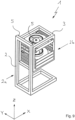
- the device 1 shows a device 1 according to the invention in a perspective representation.
- the device 1 comprises a base frame 2, which in the present case has frames which are connected to one another essentially at right angles and have rectangular tubes.
- the embodiment shown here is an example and represents only one possible embodiment for the base frame 2.
- Between two sides 2a, 2b of the base frame 2--having frames spaced apart from one another--a storage unit 3 is arranged, which serves to accommodate edge bands 4.
- the structure of the storage unit 3 is the same as that of the base frame 2, since this also has frames which are essentially connected to one another at right angles and have rectangular tubes.
- the storage unit 3 in the embodiment shown here by way of example fits within the internal dimensions of the base frame 2, with the storage unit 3 being positioned with its opposite sides 3a, 3b on the sides 2a, 2b of the Base frame 2 is guided linearly displaceable.
- the storage unit 3 is parallel to its own Pages 3a, 3b extending length constructed shorter than the base frame 2, so that they can be displaced relative to the base frame 2 within this with a corresponding stroke length a.
- rails 5 are arranged on the base frame 2 in a suitable manner.
- one of these rails 5 can be arranged on one of the opposite inner surfaces of the frames extending between the two sides 2a, 2b of the base frame 2, so that each of the sides 2a, 2b has two such rails 5.
- Areas of the storage unit 3 that correspond to these rails 5 ultimately enable their linear mobility relative to the base frame 2.
- the linear displacement of the storage unit 3 is preferably carried out by a drive that cannot be seen here; it can of course be done manually as an alternative or in addition to this.
- a look at the storage unit 3 makes it clear that it has a large number of support elements 6a, 6b arranged on its two sides 3a, 3b.
- the support elements 6a, 6b are designed like rails, which each extend perpendicularly to the length of the storage unit 3 on the two sides 2a, 2b of the base frame 2.
- the support elements 6a, 6b are arranged on the inner surfaces of the rectangular tubes of the frames located on each side 3a, 3b of the storage unit 3, as can be seen.
- the support elements 6a, 6b can be mounted on the sides 3a, 3b of the storage unit 3 so as to be linearly displaceable with respect to their lateral distance from one another in a manner that is not apparent.
- the support elements 6a, 6b divide the interior of the storage unit 3 into individual storage locations 7, with two opposing support elements 6a, 6b define a storage location 7.
- the storage locations 7 defined in this way serve to accommodate the edge bands 4, which in the present case are arranged at least in sections rolled up to form an edge roll within a cassette 4a.
- the cassettes 4a have side faces corresponding to the support elements 6a, 6b, which enable them to be pushed into and pulled out of the storage unit 3 accordingly.
- the individual storage locations 7 can also be defined by floor elements, which then extend at least partially between the sides 3a, 3b of the storage unit 3.
- the floor elements can be fixedly or slidably connected to the storage unit 3, so that they allow the pull-out of the storage unit 3 in the sense of a drawer.
- the floor elements allow edge bands 4 to be received directly, for example by being placed on the floor elements.
- the base elements can also be combined with the support elements 6a, 6b receiving the cassettes 4a.
- the support elements 6a, 6b are used to support floor elements, so that edge bands 4 can also be arranged directly in the storage unit 3 in this way.
- what was said above in relation to the support elements 6a, 6b can also apply to these floor elements, with regard to the possible change in distance between them due to a displaceable connection with the storage unit 3.
- the device 1 or the storage unit 3 can have a drive unit, not shown in detail, via which an edge band 4 can be actively driven at least in sections if required.
- the drive unit can either directly interact with the respective edge band 4 or with a cassette 4a containing the edge band 4.
- the device 1 or the storage unit 3 can have a brake unit, also not shown in detail, via which an edge band 4 can be braked and/or fixed with respect to its mobility.
- the braking unit can interact either directly with the respective edge band 4 or with a cassette 4a containing the edge band 4.
- the device 1 or the storage unit 3 can also have a cutting arrangement, also not shown in detail, by means of which a section of an edge band 4 can be separated.
- the cutting arrangement can interact either directly with the respective edge band 4 or with a cassette 4a containing the edge band 4.
- the drive unit or braking unit or cutting arrangement can also be at least part of a cassette 4 which can be controlled via a corresponding control of the device 1 or the storage unit 3 .
- a division into two would also be conceivable in that the cassettes 4a comprise the corresponding mechanical parts of the drive unit or braking unit or cutting arrangement, while the device 1 or the storage unit 3 have the corresponding drive for this, which can then be coupled to them.
- the device 1 can be aligned in such a way that its storage unit 3 - as in 1 can be seen - parallel to a vertical Z relative to the base frame 2 is linearly displaceable.
- the device 1 can of course also be used in an orientation rotated by 90°, so that its storage unit 3 can be linearly displaced parallel to a horizontal line X with respect to the base frame 2 .
- FIG. 2 shows the top view of an edging system 8, which includes an edging machine 9 and the device 1 explained in more detail above.
- the device 1 is located directly in front of the edging machine 9 in relation to a distance direction Y running at right angles to the horizontal X and the vertical Z.
- the device 1 is arranged in the area of the edging machine 8 in such a way that one of the edge bands 4 arranged in the device 1 is led directly out of the storage unit 3 of the device 1 into the edging machine 9 .
- the position of the device 1 is chosen so that the edge band 4 runs directly into an edge feed 9a of the edging machine 9, through which it is used in a manner not shown for edging panels, in particular wood-based panels.
- the storage location 7 of the device 1 stocked with the desired edging strip 4 was arranged in the plane of the edging supply 9a, in that its storage unit 3 was linearly displaced by a movement running parallel to the vertical Z in the present case.
- the edging system 8 can be designed in such a way that the device 1 can be displaced relative to the edging machine 9, which is related to the representation of FIG 2 their displacement in and against parallels Directions to the horizontal X and/or to the distance direction Y means.
- the device can be displaceable relative to the device 1 in a parallel direction running opposite to the distance direction Y, in order to be able to carry out any maintenance work.
- free access to the edge feed 9a is made possible.
- this mobility can also be used to move the device 1, for example, between two edging machines 9 spaced parallel to one another, as required, in order to be able to provide the required edging tape 4 on one or the other edging machine 9.
- Figures 3 to 7 each show expanded expansion stages of the device 1, through which its performance in relation to the provision of edge bands 4 can be increased.
- FIG 3 shows a first extended stage in which the device 1 is combined with a manipulator 10.
- An exemplary configuration of the manipulator 10 as a stacker crane (RBG) is shown here, which has a linear displaceability running parallel to the lifting direction of the device 1 .
- the manipulator 10 specifically has a lifting unit 10b which is mounted in a linearly movable manner in a frame 10a and which can accommodate at least one edging strip 4 or a cassette 4a fitted with an edging strip 4 .
- the manipulator 10 is used to equip the device 1 with edge bands 4 or with cassettes 4a each containing an edge band 4 and to empty the device 1. In this expansion stage, the manipulator 10 can be loaded manually.
- the manipulator 10 can be moved synchronously with the device 1 by means of a corresponding coupling. This coupling can take place mechanically and/or by means of control technology. Via a corresponding control of the manipulator 10, the device 1 can also be loaded and unloaded during operation.
- the storage arrangement 11 is in the present case like a shelving system with lateral support elements 11a in the form of rails, as already explained above for device 1, which have a large number of stacked slots 11b for edge bands 4 or cassettes 4a each containing an edge band 4.
- edgebands 4 that can be kept available in the storage arrangement 11 can now be removed individually or at least in pairs from this and transferred to the device 1, with the storage locations 7 of the storage unit 3 being stocked accordingly.
- the linearly displaceable lifting unit 10b of the manipulator 10 is moved into the required level of the storage arrangement 11, where it removes an edge band 4 or the cassette 4a containing the edge band 4 from the respective slot 11b. If necessary, the lifting unit 10b of the manipulator 10 then moves to another level in order to transfer the edgeband 4 or the cassette 4a to a free storage location 7 of the storage unit 3 of the device 1 . Of course, this can also be done in the opposite way, in order to feed edgebands 4 or cassettes 4a out of the device 1 to the storage arrangement 11 .
- FIG 5 illustrates the structure of a further expansion stage, which also includes a transfer device 12.
- the transfer device 12 is arranged on the device 1 in the present case, where it corresponds to a machine bearing 13 .
- the machine bearing 13 is located in a position that is not shown in detail Way above or directly on the edging machine 9.
- the storage arrangement 11 serves as a buffer for edging strips 4 or cassettes 4a, while the transfer device 12 preferably automatically supplies and removes new edging strips 4 or cassettes 4a.
- edge bands 4 or cassettes 4a that can be kept available in the machine storage 13 provided here, for example, close to the machine can be transferred to the manipulator 10 individually or at least in pairs.
- edge bands 4 or cassettes 4a arranged in the storage unit 3 and/or the storage arrangement 11 can be transferred individually or at least in pairs by the manipulator 10 to the transfer device 12 .
- FIG. 6 shows an expansion stage that is a doubling of the already in 4 structure shown includes.
- two devices 1 are provided here, each of which is combined with its own manipulator 10 and a storage arrangement 11 located on the respective manipulator 10 .
- This structure allows the two devices 1 to work alternately, which means that correspondingly high cycle rates can be achieved.
- the edging machine 9 has two edge feeds 9a (not shown in detail here) in order to be able to process the edge bands 4 of the respective device 1.
- FIG. 7 is a final possible expansion stage, which is a doubling of the already in figure 5 structure shown includes.
- two devices 1 are also provided here, each of which is combined with its own manipulator 10 and a storage arrangement 11 located on the respective manipulator 10, as well as a transfer device 12 and a machine bearing 13, in particular close to the machine. Again, the two devices 1 can work alternately to to achieve a high cycle rate for the edging of panels.
- the device 1 of all expansion stages can be equipped with at least one reading module, which is not shown in detail.
- the reading module can be arranged in the area of the storage unit 3 . It is also conceivable that each storage location 7 of the storage unit 3 is equipped with such a reading module.
- the goal is the automated transmission of information about the respective edge bands 4 or cassettes 4a, which are currently in the storage unit 3 or have been removed from it or have just been added.
- the edge bands 4 or cassettes 4a can be equipped with a corresponding transmission module on which the required information is stored.
- Such a transmission module can preferably contain at least one RFID chip or be designed as such.
- the reading module or the reading modules are set up to correspond with the transmission modules. This can be done in one direction or in both directions, which means the mere reading of data or a combination of reading and writing of data by the read module to a transmitter module.
- the device 1 according to the invention can advantageously include at least one interface, which is not shown in detail here. This interface is then designed to be coupled to at least one other component or machine, in particular mechanically and/or in a data-transmitting manner. In this way, all components or machines of an edging system 8 can be controlled via a corresponding controller.
- the frames located on one of the two sides 2a, 2b of the base frame 2 are connected to one another via two rectangular tubes extending between them parallel to the horizontal X.
- the visible base frame 2 has a total of four rectangular tubes connecting each of its two frames located on one side 2a, 2b and extending parallel to the horizontal X between the opposite corners of said frames.
- those rectangular tubes connecting the frames lie one above the other in relation to the vertical Z, so that the base frame 2 is essentially U-shaped in its plan view, which is not shown in detail here.
- the base frame 2 manages with a frame located on only one side 2a, while the opposite side 2b is virtually frameless.
- the lower area of the base frame 2 which is made up of rectangular tubes, is designed to be closed.
- the two rectangular tubes running parallel to the horizontal X each extend from a lower corner of the side 2a located frame away, these being connected to one another at the ends via a rectangular tube running parallel to the spacing direction Y.
Landscapes
- Life Sciences & Earth Sciences (AREA)
- Engineering & Computer Science (AREA)
- Wood Science & Technology (AREA)
- Forests & Forestry (AREA)
- Mechanical Engineering (AREA)
- Manufacturing & Machinery (AREA)
- Warehouses Or Storage Devices (AREA)
- Basic Packing Technique (AREA)
- Unwinding Webs (AREA)
- Replacement Of Web Rolls (AREA)
Claims (14)
- Dispositif pour poser les bandes de chant (8), comportant une machine pour poser les bandes de chant (9) et au moins un dispositif (1) pour fournir des bandes de chant (4), comprenant une unité de stockage (3) comportant des zones de stockage individuelles (7), qui sont conçues pour être au moins indirectement chargées avec des bandes de chant (4), en particulier des bandes de chant, qui forment chacune un rouleau de chant au moins dans certaines parties,
caractérisé en ceque l'au moins un dispositif (1) est disposé dans la zone de la machine pour poser les bandes de chant (8) de manière à ce qu'au moins une bande de chant (4), pouvant être placée dans le dispositif (1), puisse être alimentée directement de l'unité de stockage (3) du dispositif (1) à la machine pour poser les bandes de chant (9), au moins dans certaines parties, etqu'au moins une des zones de stockage (7) est conçue pour recevoir au moins une cassette (4a), comportant la bande de chant (4) au moins partiellement, et l'unité de stockage (3) est disposée parallèlement à une verticale (Z) et de manière à pouvoir se déplacer linéairement dans ou sur un cadre de base (2), etque les zones de stockage (7) du dispositif (1), qui peuvent être chargées au moins indirectement avec une bande de chant (4) chacune, peuvent être placées dans le plan d'une alimentation de chants (9a) de la machine pour poser les bandes de chant (9) par un déplacement linéaire de l'unité de stockage (3) relatif au cadre de base (2), etque le dispositif (1) comporte en outre un ensemble de coupe, par lequel une partie de la bande de chant (4), surtout une partie déroulée d'un rouleau de chant, peut être séparée. - Dispositif pour poser les bandes de chant (8) selon la revendication 1,
caractérisé en ce
que l'unité de stockage (3) comporte deux côtés opposés (3a, 3b), dans lequel au moins une des zones de stockage (7) comporte au moins un élément de plancher s'étendant au moins partiellement entre ces côtés (3a, 3b), et/ou au moins un élément de support (6a, 6b), disposé dans la zone de chaque côté (3a, 3b). - Dispositif pour poser les bandes de chant (8) selon la revendication 2,
caractérisé en ce
que l'élément de plancher et/ou les éléments de support (6a, 6b) de l'au moins une zone de stockage (7) sont montés sur l'unité de stockage (3) de manière à pouvoir se déplacer linéairement. - Dispositif pour poser les bandes de chant (8) selon l'une quelconque des revendications précédentes,
caractérisé en ce
que l'unité de stockage (3) ou chaque zone de stockage (7) de l'unité de stockage (3) est équipée d'au moins un module de lecture, qui est adapté pour correspondre à un module d'émission, en particulier une puce RFID, d'une bande de chant (4) ou d'une cassette (4a) contenant la bande de chant (4). - Dispositif pour poser les bandes de chant (8) selon l'une quelconque des revendications précédentes, caractérisé en ce
que l'unité de stockage (3) peut être déplacée par rapport au cadre de base (2) par un entraînement, en particulier un entraînement automatisé, et/ou manuellement. - Dispositif pour poser les bandes de chant (8) selon l'une quelconque des revendications précédentes,
caractérisé par
au moins une interface, qui peut être couplée à au moins un autre composant ou une machine, en particulier mécaniquement et/ou par transmission de données. - Dispositif pour poser les bandes de chant (8) selon l'une quelconque des revendications précédentes,
caractérisé par
une unité d'entraînement, par laquelle une bande de chant (4), en particulier une bande de chant (4), disposée au moins partiellement à l'intérieur d'une cassette (4a), peut être entraînée activement au moins dans certaines parties. - Dispositif pour poser les bandes de chant (8) selon l'une quelconque des revendications précédentes,
caractérisé par une unité de freinage, par laquelle une bande de chant (4), en particulier une bande de chant (4), disposée au moins partiellement à l'intérieur d'une cassette (4a), peut être freinée et/ou fixée par rapport à sa mobilité. - Dispositif pour poser les bandes de chant (8) selon l'une quelconque des revendications précédentes,
caractérisé par un manipulateur (10), au moyen duquel chaque zone de stockage (7) peut être équipée d'une bande de chant (4), ou d'une cassette (4a), contenant au moins partiellement la bande de chant (4a), et peut être vidée. - Dispositif pour poser les bandes de chant (8) selon la revendication 9,
caractérisé par
un dispositif de stockage (11), à partir duquel des bandes de chant (4), pouvant y être stockées, peuvent être prélevées individuellement ou au moins par deux par le manipulateur (10), et transférées vers les zones de stockage (7) de l'unité de stockage (3) pour la charger, dans lequel des bandes de chant (4), qui peuvent être disposées dans l'unité de stockage (3), peuvent être prélevées individuellement ou au moins par deux par le manipulateur (10) hors de celle-ci, et transférées vers le dispositif de stockage (11). - Dispositif pour poser les bandes de chant (8) selon la revendication 9 ou 10,
caractérisé par
un dispositif de transfert (12), par lequel des bandes de chant (4), qui peuvent être stockées dans un magasin de machines (13), peuvent être transférées individuellement ou au moins par deux au manipulateur (10), dans lequel des bandes de chant (4), qui peuvent être disposées dans l'unité de stockage (3) et/ou le dispositif de stockage (11), peuvent être transférées individuellement ou au moins par deux par le manipulateur (10) au dispositif de transfert (12). - Dispositif pour poser les bandes de chant (8) selon l'une quelconque des revendications précédentes,
caractérisé en ce
que le manipulateur (10) comporte au moins un axe de rotation vertical et/ou au moins un axe de levage vertical. - Dispositif pour poser les bandes de chant (8) selon la revendication 12,
caractérisé en ce
qu'au moins deux dispositifs de stockage (11) sont disposés dans la zone du manipulateur (10). - Utilisation d'un dispositif pour poser les bandes de chant (8) selon l'une quelconque des revendications précédentes pour fournir des bandes de chant (4), dans lequel la bande de chant (4) respective est prélevée d'une cassette la contenant au moins partiellement, et qui est reçue par l'une des zones de stockage (7).
Applications Claiming Priority (2)
| Application Number | Priority Date | Filing Date | Title |
|---|---|---|---|
| DE102019122413.6A DE102019122413A1 (de) | 2019-08-21 | 2019-08-21 | Vorrichtung zur Bereitstellung von Kantenbändern sowie Bekantungsanlage mit einer solchen Vorrichtung |
| PCT/EP2020/073127 WO2021032753A1 (fr) | 2019-08-21 | 2020-08-18 | Dispositif pour fournir des bandes de chant, système de fabrication de chants comprenant un dispositif de ce type |
Publications (3)
| Publication Number | Publication Date |
|---|---|
| EP3856477A1 EP3856477A1 (fr) | 2021-08-04 |
| EP3856477B1 true EP3856477B1 (fr) | 2023-06-07 |
| EP3856477C0 EP3856477C0 (fr) | 2023-06-07 |
Family
ID=72234814
Family Applications (1)
| Application Number | Title | Priority Date | Filing Date |
|---|---|---|---|
| EP20761171.6A Active EP3856477B1 (fr) | 2019-08-21 | 2020-08-18 | Dispositif pour approvisionner des bandes de chant, ainsi que machine pour poser les bandes de chant comprenant un tel dispositif |
Country Status (8)
| Country | Link |
|---|---|
| US (1) | US20220193944A1 (fr) |
| EP (1) | EP3856477B1 (fr) |
| CN (1) | CN113853283B (fr) |
| BR (1) | BR112021017237A2 (fr) |
| CA (1) | CA3139517A1 (fr) |
| DE (1) | DE102019122413A1 (fr) |
| PL (1) | PL3856477T3 (fr) |
| WO (1) | WO2021032753A1 (fr) |
Citations (1)
| Publication number | Priority date | Publication date | Assignee | Title |
|---|---|---|---|---|
| DE20204285U1 (de) * | 2002-03-18 | 2002-07-04 | Paul Ott Gmbh Maschinenfabrik | Vorrichtung zur Lagerung von Kantenmagazinen |
Family Cites Families (17)
| Publication number | Priority date | Publication date | Assignee | Title |
|---|---|---|---|---|
| DE7031331U (de) * | 1970-08-21 | 1971-09-02 | Klessmann Ima Norte Maschfab | Trommelmagazin fuer furnierkanten-maschine. |
| IT1058245B (it) * | 1975-06-12 | 1982-04-10 | Meyer & Schwabedissen F Gmbh & | Magazzino di strisce per una macchina applicatrice |
| DE3914461C2 (de) * | 1989-05-02 | 1997-03-27 | Klessmann Ima Norte Maschfab | Maschine zum Anleimen von Kantenmaterial an plattenförmige Werkstücke |
| DE19917741A1 (de) * | 1999-04-20 | 2000-10-26 | Ima Maschinenfabriken Klessmann Gmbh | Vorrichtung zum Anfahren eines Kantenstreifens an eine Schmalflächenseite einer eckigen Platte |
| DE10123327C1 (de) * | 2001-05-12 | 2002-11-28 | Koenig & Bauer Ag | Zwischenspeichervorrichtung für Stapel von Druckerzeugnissen |
| PL1860596T3 (pl) * | 2006-05-24 | 2011-02-28 | Homag Holzbearbeitungssysteme Ag | Urządzenie do identyfikacji, przeznaczone do zarządzania zasobami towarów z metra |
| EP1977869B1 (fr) * | 2007-04-04 | 2009-12-16 | Homag Holzbearbeitungssysteme AG | Dispositif d'alimentation pour machines d'usinage |
| DE102009010792A1 (de) * | 2009-02-26 | 2010-09-02 | Lübke, Wolfgang | Mehrachsroboter zum Bestücken einer Kantenzuführeinrichtung |
| DE102009021676A1 (de) * | 2009-05-18 | 2010-11-25 | Homag Holzbearbeitungssysteme Ag | Zufuhrvorrichtung |
| DE202015105929U1 (de) * | 2015-11-06 | 2015-11-20 | Holz-Her Gmbh | Kantenbearbeitungsmaschine |
| CN206156173U (zh) * | 2016-10-26 | 2017-05-10 | 长沙开元仪器股份有限公司 | 一种存储装置 |
| DE102016224488A1 (de) * | 2016-12-08 | 2018-06-14 | Homag Gmbh | Versorgungseinrichtung, Beschichtungsmaschine sowie Bevorratungsanordnung |
| DE102017117326B4 (de) * | 2017-07-31 | 2023-08-10 | Airbus Operations Gmbh | System zum Handhaben von Behältern und anderen Objekten in einem Frachtraum eines Fahrzeugs |
| DE102017125936A1 (de) * | 2017-11-07 | 2019-05-09 | Ima Klessmann Gmbh Holzbearbeitungssysteme | Kantenverarbeitungsanlage |
| DE102017125937A1 (de) * | 2017-11-07 | 2019-05-09 | Ima Klessmann Gmbh Holzbearbeitungssysteme | Kantenbearbeitungsanordnung |
| CN208056916U (zh) * | 2018-04-12 | 2018-11-06 | 钱耀军 | 一种建筑工程管理资料的保险柜 |
| CN111391061B (zh) * | 2020-04-27 | 2022-06-28 | 南兴装备股份有限公司 | 一种自动封边机的加工方法 |
-
2019
- 2019-08-21 DE DE102019122413.6A patent/DE102019122413A1/de active Pending
-
2020
- 2020-08-18 CN CN202080037610.2A patent/CN113853283B/zh active Active
- 2020-08-18 EP EP20761171.6A patent/EP3856477B1/fr active Active
- 2020-08-18 CA CA3139517A patent/CA3139517A1/fr active Pending
- 2020-08-18 PL PL20761171.6T patent/PL3856477T3/pl unknown
- 2020-08-18 US US17/606,393 patent/US20220193944A1/en active Pending
- 2020-08-18 WO PCT/EP2020/073127 patent/WO2021032753A1/fr unknown
- 2020-08-18 BR BR112021017237A patent/BR112021017237A2/pt unknown
Patent Citations (1)
| Publication number | Priority date | Publication date | Assignee | Title |
|---|---|---|---|---|
| DE20204285U1 (de) * | 2002-03-18 | 2002-07-04 | Paul Ott Gmbh Maschinenfabrik | Vorrichtung zur Lagerung von Kantenmagazinen |
Also Published As
| Publication number | Publication date |
|---|---|
| EP3856477A1 (fr) | 2021-08-04 |
| CA3139517A1 (fr) | 2021-02-25 |
| CN113853283A (zh) | 2021-12-28 |
| PL3856477T3 (pl) | 2023-09-25 |
| CN113853283B (zh) | 2023-09-05 |
| DE102019122413A1 (de) | 2021-02-25 |
| WO2021032753A1 (fr) | 2021-02-25 |
| BR112021017237A2 (pt) | 2022-05-10 |
| US20220193944A1 (en) | 2022-06-23 |
| EP3856477C0 (fr) | 2023-06-07 |
Similar Documents
| Publication | Publication Date | Title |
|---|---|---|
| EP3419926B1 (fr) | Entraînement télescopique, transtockeur comportant celui-ci et procédé de fonctionnement ainsi qu'utilisation associés | |
| DE102007017365B4 (de) | Verfahren zur Lagerung von Lagergut in einem Lagerregal mit mehreren Regaleinheiten und einem Transportschacht sowie ein solches Lagerregal | |
| DE202016009161U1 (de) | Lagersystem | |
| EP3579987B1 (fr) | Magasin d'outils de cintrage et procédé de chargement d'une presse-plieuse | |
| EP1638866A1 (fr) | Procede et dispositif pour manipuler des auxiliaires de chargement | |
| DE102013114275A1 (de) | Regallagersystem mit Förderfahrzeug-Hebevorrichtung | |
| EP3475212B1 (fr) | Entrepôt à haut rayonnage comprenant, à l'intérieur, des transstockeurs destinés à stocker et déstocker ou transférer des marchandises entreposées | |
| WO2016092019A1 (fr) | Dispositif de reprise de charge | |
| AT511162A1 (de) | Regallagersystem | |
| DE202004004620U1 (de) | Lagersystem | |
| WO2013044895A1 (fr) | Dispositif de déplacement d'unités de transport | |
| DE19946800A1 (de) | Regallager | |
| DE3133108C1 (de) | Einrichtung zur Lagerung von stangenfoermigem Material und zur Versorgung einer Trennmaschine mit diesen Material | |
| EP3856477B1 (fr) | Dispositif pour approvisionner des bandes de chant, ainsi que machine pour poser les bandes de chant comprenant un tel dispositif | |
| EP1632447B1 (fr) | Appareil de commande d'entrepôt et installation pour préparer et entreposer des bobines de papier et amener celles-ci à au moins un porte-bobine et procédé pour son fonctionnement. | |
| DE2802345A1 (de) | Vorrichtung zum umschlagen von ladeeinheiten | |
| DE202008008350U1 (de) | Lastaufnahmemittel zur Ein- und Auslagerung von Lasten an bzw. von Lagerplätzen einer Regalanordnung | |
| EP4072803A1 (fr) | Dispositif de fourniture de bandes de chant, système de placage de chant doté d'un tel dispositif, et procédé de changement d'un rouleau de chant ou d'une cartouche de chant | |
| DE19946781C2 (de) | Bediengerät für ein Regallager | |
| EP1862405B1 (fr) | Procédé destiné à saisir une marchandise à l'aide d'éléments de préhension dans un dispositif de stockage et de déstockage et dispositif correspondant | |
| AT14863U1 (de) | Lastaufnahmevorrichtung mit ausfahrbaren Teleskoparmen und um einen Schwenkwinkel verschwenkbare Mitnehmer auf diesen | |
| DE1910603A1 (de) | Transportgeraet mit verschiebbaren Hubgabeln | |
| AT7107U1 (de) | Lagersystem | |
| EP0013033A1 (fr) | Dispositif de prélèvement, en particulier pour prélever un matériau en barres ou analogue, des cassettes d'un rayonnage | |
| DE4314600B4 (de) | Vorrichtung zur lageweisen Stapelung von gruppierten Gegenständen |
Legal Events
| Date | Code | Title | Description |
|---|---|---|---|
| STAA | Information on the status of an ep patent application or granted ep patent |
Free format text: STATUS: UNKNOWN |
|
| STAA | Information on the status of an ep patent application or granted ep patent |
Free format text: STATUS: THE INTERNATIONAL PUBLICATION HAS BEEN MADE |
|
| PUAI | Public reference made under article 153(3) epc to a published international application that has entered the european phase |
Free format text: ORIGINAL CODE: 0009012 |
|
| STAA | Information on the status of an ep patent application or granted ep patent |
Free format text: STATUS: REQUEST FOR EXAMINATION WAS MADE |
|
| 17P | Request for examination filed |
Effective date: 20210430 |
|
| AK | Designated contracting states |
Kind code of ref document: A1 Designated state(s): AL AT BE BG CH CY CZ DE DK EE ES FI FR GB GR HR HU IE IS IT LI LT LU LV MC MK MT NL NO PL PT RO RS SE SI SK SM TR |
|
| RIN1 | Information on inventor provided before grant (corrected) |
Inventor name: STUKE, BJOERN Inventor name: PETKER, RENE Inventor name: HUESENER, STEFAN Inventor name: HEIDENREICH, TIMO Inventor name: GERDWILKER, HENDRIK Inventor name: KROEKER, SIMON Inventor name: KOTTKAMP, TIM Inventor name: CULEMANN, LARS |
|
| GRAP | Despatch of communication of intention to grant a patent |
Free format text: ORIGINAL CODE: EPIDOSNIGR1 |
|
| STAA | Information on the status of an ep patent application or granted ep patent |
Free format text: STATUS: GRANT OF PATENT IS INTENDED |
|
| DAV | Request for validation of the european patent (deleted) | ||
| DAX | Request for extension of the european patent (deleted) | ||
| INTG | Intention to grant announced |
Effective date: 20221121 |
|
| GRAS | Grant fee paid |
Free format text: ORIGINAL CODE: EPIDOSNIGR3 |
|
| GRAA | (expected) grant |
Free format text: ORIGINAL CODE: 0009210 |
|
| STAA | Information on the status of an ep patent application or granted ep patent |
Free format text: STATUS: THE PATENT HAS BEEN GRANTED |
|
| AK | Designated contracting states |
Kind code of ref document: B1 Designated state(s): AL AT BE BG CH CY CZ DE DK EE ES FI FR GB GR HR HU IE IS IT LI LT LU LV MC MK MT NL NO PL PT RO RS SE SI SK SM TR |
|
| REG | Reference to a national code |
Ref country code: GB Ref legal event code: FG4D Free format text: NOT ENGLISH |
|
| REG | Reference to a national code |
Ref country code: CH Ref legal event code: EP Ref country code: AT Ref legal event code: REF Ref document number: 1573645 Country of ref document: AT Kind code of ref document: T Effective date: 20230615 Ref country code: DE Ref legal event code: R096 Ref document number: 502020003722 Country of ref document: DE |
|
| U01 | Request for unitary effect filed |
Effective date: 20230607 |
|
| U07 | Unitary effect registered |
Designated state(s): AT BE BG DE DK EE FI FR IT LT LU LV MT NL PT SE SI Effective date: 20230614 |
|
| U20 | Renewal fee paid [unitary effect] |
Year of fee payment: 4 Effective date: 20230728 |
|
| REG | Reference to a national code |
Ref country code: LT Ref legal event code: MG9D |
|
| PG25 | Lapsed in a contracting state [announced via postgrant information from national office to epo] |
Ref country code: NO Free format text: LAPSE BECAUSE OF FAILURE TO SUBMIT A TRANSLATION OF THE DESCRIPTION OR TO PAY THE FEE WITHIN THE PRESCRIBED TIME-LIMIT Effective date: 20230907 Ref country code: ES Free format text: LAPSE BECAUSE OF FAILURE TO SUBMIT A TRANSLATION OF THE DESCRIPTION OR TO PAY THE FEE WITHIN THE PRESCRIBED TIME-LIMIT Effective date: 20230607 |
|
| PG25 | Lapsed in a contracting state [announced via postgrant information from national office to epo] |
Ref country code: RS Free format text: LAPSE BECAUSE OF FAILURE TO SUBMIT A TRANSLATION OF THE DESCRIPTION OR TO PAY THE FEE WITHIN THE PRESCRIBED TIME-LIMIT Effective date: 20230607 Ref country code: HR Free format text: LAPSE BECAUSE OF FAILURE TO SUBMIT A TRANSLATION OF THE DESCRIPTION OR TO PAY THE FEE WITHIN THE PRESCRIBED TIME-LIMIT Effective date: 20230607 Ref country code: GR Free format text: LAPSE BECAUSE OF FAILURE TO SUBMIT A TRANSLATION OF THE DESCRIPTION OR TO PAY THE FEE WITHIN THE PRESCRIBED TIME-LIMIT Effective date: 20230908 |
|
| PGFP | Annual fee paid to national office [announced via postgrant information from national office to epo] |
Ref country code: PL Payment date: 20230712 Year of fee payment: 4 |
|
| PG25 | Lapsed in a contracting state [announced via postgrant information from national office to epo] |
Ref country code: SK Free format text: LAPSE BECAUSE OF FAILURE TO SUBMIT A TRANSLATION OF THE DESCRIPTION OR TO PAY THE FEE WITHIN THE PRESCRIBED TIME-LIMIT Effective date: 20230607 |
|
| PG25 | Lapsed in a contracting state [announced via postgrant information from national office to epo] |
Ref country code: IS Free format text: LAPSE BECAUSE OF FAILURE TO SUBMIT A TRANSLATION OF THE DESCRIPTION OR TO PAY THE FEE WITHIN THE PRESCRIBED TIME-LIMIT Effective date: 20231007 |
|
| PG25 | Lapsed in a contracting state [announced via postgrant information from national office to epo] |
Ref country code: SM Free format text: LAPSE BECAUSE OF FAILURE TO SUBMIT A TRANSLATION OF THE DESCRIPTION OR TO PAY THE FEE WITHIN THE PRESCRIBED TIME-LIMIT Effective date: 20230607 Ref country code: SK Free format text: LAPSE BECAUSE OF FAILURE TO SUBMIT A TRANSLATION OF THE DESCRIPTION OR TO PAY THE FEE WITHIN THE PRESCRIBED TIME-LIMIT Effective date: 20230607 Ref country code: RO Free format text: LAPSE BECAUSE OF FAILURE TO SUBMIT A TRANSLATION OF THE DESCRIPTION OR TO PAY THE FEE WITHIN THE PRESCRIBED TIME-LIMIT Effective date: 20230607 Ref country code: IS Free format text: LAPSE BECAUSE OF FAILURE TO SUBMIT A TRANSLATION OF THE DESCRIPTION OR TO PAY THE FEE WITHIN THE PRESCRIBED TIME-LIMIT Effective date: 20231007 Ref country code: CZ Free format text: LAPSE BECAUSE OF FAILURE TO SUBMIT A TRANSLATION OF THE DESCRIPTION OR TO PAY THE FEE WITHIN THE PRESCRIBED TIME-LIMIT Effective date: 20230607 |
|
| REG | Reference to a national code |
Ref country code: DE Ref legal event code: R097 Ref document number: 502020003722 Country of ref document: DE |
|
| PG25 | Lapsed in a contracting state [announced via postgrant information from national office to epo] |
Ref country code: MC Free format text: LAPSE BECAUSE OF FAILURE TO SUBMIT A TRANSLATION OF THE DESCRIPTION OR TO PAY THE FEE WITHIN THE PRESCRIBED TIME-LIMIT Effective date: 20230607 |
|
| REG | Reference to a national code |
Ref country code: CH Ref legal event code: PL |
|
| PG25 | Lapsed in a contracting state [announced via postgrant information from national office to epo] |
Ref country code: MC Free format text: LAPSE BECAUSE OF FAILURE TO SUBMIT A TRANSLATION OF THE DESCRIPTION OR TO PAY THE FEE WITHIN THE PRESCRIBED TIME-LIMIT Effective date: 20230607 |
|
| PLBE | No opposition filed within time limit |
Free format text: ORIGINAL CODE: 0009261 |
|
| STAA | Information on the status of an ep patent application or granted ep patent |
Free format text: STATUS: NO OPPOSITION FILED WITHIN TIME LIMIT |
|
| PG25 | Lapsed in a contracting state [announced via postgrant information from national office to epo] |
Ref country code: CH Free format text: LAPSE BECAUSE OF NON-PAYMENT OF DUE FEES Effective date: 20230831 |
|
| 26N | No opposition filed |
Effective date: 20240308 |
|
| REG | Reference to a national code |
Ref country code: IE Ref legal event code: MM4A |