EP3856477B1 - Device for supplying edgebands as well as edgebanding machine with such device - Google Patents
Device for supplying edgebands as well as edgebanding machine with such device Download PDFInfo
- Publication number
- EP3856477B1 EP3856477B1 EP20761171.6A EP20761171A EP3856477B1 EP 3856477 B1 EP3856477 B1 EP 3856477B1 EP 20761171 A EP20761171 A EP 20761171A EP 3856477 B1 EP3856477 B1 EP 3856477B1
- Authority
- EP
- European Patent Office
- Prior art keywords
- storage unit
- unit
- edgebanding
- edgeband
- storage
- Prior art date
- Legal status (The legal status is an assumption and is not a legal conclusion. Google has not performed a legal analysis and makes no representation as to the accuracy of the status listed.)
- Active
Links
- 238000003860 storage Methods 0.000 claims description 175
- 238000012546 transfer Methods 0.000 claims description 15
- 238000005520 cutting process Methods 0.000 claims description 8
- 238000006073 displacement reaction Methods 0.000 claims description 5
- 230000008878 coupling Effects 0.000 claims description 4
- 238000010168 coupling process Methods 0.000 claims description 4
- 238000005859 coupling reaction Methods 0.000 claims description 4
- 238000007688 edging Methods 0.000 description 83
- 230000005540 biological transmission Effects 0.000 description 8
- 239000002023 wood Substances 0.000 description 8
- 238000011161 development Methods 0.000 description 5
- 230000008901 benefit Effects 0.000 description 3
- 238000013461 design Methods 0.000 description 3
- 238000012423 maintenance Methods 0.000 description 3
- 238000009826 distribution Methods 0.000 description 2
- 238000007373 indentation Methods 0.000 description 2
- 239000000463 material Substances 0.000 description 2
- 238000000034 method Methods 0.000 description 2
- 230000008569 process Effects 0.000 description 2
- 230000006978 adaptation Effects 0.000 description 1
- 230000008859 change Effects 0.000 description 1
- 238000000576 coating method Methods 0.000 description 1
- 239000003086 colorant Substances 0.000 description 1
- 238000004891 communication Methods 0.000 description 1
- 238000010924 continuous production Methods 0.000 description 1
- 230000007547 defect Effects 0.000 description 1
- 230000001419 dependent effect Effects 0.000 description 1
- 238000005516 engineering process Methods 0.000 description 1
- 238000009434 installation Methods 0.000 description 1
- 230000010354 integration Effects 0.000 description 1
- 239000004922 lacquer Substances 0.000 description 1
- 239000007788 liquid Substances 0.000 description 1
- 238000002844 melting Methods 0.000 description 1
- 230000008018 melting Effects 0.000 description 1
- 230000002093 peripheral effect Effects 0.000 description 1
- 230000035484 reaction time Effects 0.000 description 1
- 230000008707 rearrangement Effects 0.000 description 1
- 239000007787 solid Substances 0.000 description 1
- 239000002983 wood substitute Substances 0.000 description 1
Images


Classifications
-
- B—PERFORMING OPERATIONS; TRANSPORTING
- B27—WORKING OR PRESERVING WOOD OR SIMILAR MATERIAL; NAILING OR STAPLING MACHINES IN GENERAL
- B27N—MANUFACTURE BY DRY PROCESSES OF ARTICLES, WITH OR WITHOUT ORGANIC BINDING AGENTS, MADE FROM PARTICLES OR FIBRES CONSISTING OF WOOD OR OTHER LIGNOCELLULOSIC OR LIKE ORGANIC MATERIAL
- B27N7/00—After-treatment, e.g. reducing swelling or shrinkage, surfacing; Protecting the edges of boards against access of humidity
- B27N7/005—Coating boards, e.g. with a finishing or decorating layer
-
- B—PERFORMING OPERATIONS; TRANSPORTING
- B27—WORKING OR PRESERVING WOOD OR SIMILAR MATERIAL; NAILING OR STAPLING MACHINES IN GENERAL
- B27D—WORKING VENEER OR PLYWOOD
- B27D5/00—Other working of veneer or plywood specially adapted to veneer or plywood
- B27D5/003—Other working of veneer or plywood specially adapted to veneer or plywood securing a veneer strip to a panel edge
Definitions
- the invention relates to an edging system comprising an edging machine and a device for preparing edge bands according to the preamble of claim 1.
- the invention is also directed to the use of an edging system according to one of the preceding claims
- Edging system is from the document EP 1 346 805 A2 known.
- Boards made of wood or wood substitutes for the furniture industry usually have at least one at least partially coated top surface before they are processed.
- the types of these coatings range from lacquer finishes to paneling with layers of real wood veneer or plastic.
- the surfaces coated in this way have increased resistance to mechanical influences and liquids.
- the narrow edges of these panels are usually only coated afterwards, for example after they have been cut to size.
- a suitable edge band is attached to the narrow sides of the panel at least in sections. Their bond with the panel is usually based on adhesion or a micro form fit through local melting.
- the edging of wood-based panels is carried out by an edging system in which the edge bands are attached with at least one edging machine in a continuous process.
- the edgebands are usually lying rolled up as edge rolls in order to be able to safely transport and store large lengths in the most compact way possible. For the simplest possible handling, these can also be arranged within a cassette and can be unwound from this if necessary. Due to the variety of colors and decors as well as thicknesses (thickness) of the panels to be edged, the edge bands, which are then also different, often have to be replaced with the appropriate variant.
- a device for providing edge bands which comprises a tower-like storage unit.
- the storage unit has individual storage locations that are designed for at least indirect fitting with edge bands.
- the storage locations are located one above the other in relation to a vertical.
- a storage place of the storage unit serves as a fixed changing place position, which corresponds to a storage table that is arranged on the outside of the storage unit and is at the same height.
- a cassette fitted with an edge roll can be inserted manually into the changing position from the storage table.
- This cassette is then sorted into another storage location within the storage unit by a handling device arranged on the opposite side of the storage unit.
- a cassette to be exchanged is first pulled out of its storage location within the storage unit by means of the handling device and transferred to the exchange location position, from where it is manually removed again and placed on the storage table, for example to insert a new edge roll.
- An edging machine is supplied with edgebands via the handling device of the device, which removes the required cassette from the storage unit and transfers it to the edging machine.
- the present invention is therefore based on the object of further developing a generic device and an edging system equipped therewith such that the provision of edging strips can take place more economically overall.
- this object is achieved in an edging system comprising an edging machine and at least one device for preparing edge bands according to claim 1.
- Advantageous configurations are the subject matter of the dependent subclaims 2 to 13.
- the device should include a base frame, with the actual storage unit now being arranged in or on this base frame in a linearly displaceable manner.
- the device according to the invention stand up on a base via its base frame and/or be attached to another component, while the storage unit designed to accommodate edge bands can be linearly displaced relative to the base frame.
- the configuration according to the invention does not require any rearrangement of edge bands or cassettes within the storage unit, since the edge band required in each case, regardless of its arrangement in one of the storage locations, is in the required level solely due to the linear mobility of the storage unit can be displaced in relation to an edging machine.
- the handling device required for the previously required distribution of edge bands within the storage unit can be omitted.
- there is no longer a compelling need to transfer the respective edge band to an edging machine since this can now be fed directly from the storage unit, in that the storage space containing the required edging band can be positioned beforehand, for example opposite an edge feed of the edging machine.
- At least one storage location of the storage unit can be designed in such a way that it can accommodate at least one edge band.
- this storage location can be designed in such a way that a loose edging strip, in particular in its form at least partially wound up to form an edging roll, can be arranged or stored in it.
- at least one of the storage locations can be designed to accommodate a cassette that at least partially contains the edging strip.
- the storage unit has two opposite sides, and the design of its storage locations can advantageously be adapted to the shape of the edge bands to be accommodated.
- at least one of the storage locations can have at least one floor element that extends at least partially between the sides of the storage unit. This can, for example, be designed in such a way that an edge band can be placed directly on this floor element or at least partially supported on it.
- at least one of the storage locations can have at least one support element arranged in the area of each side of the storage unit.
- the support elements can, for example, be designed in such a way that a cassette containing an edge band can be placed on these support elements or at least partially supported on them.
- the invention provides that the floor element and/or at least one support element of at least one storage location is mounted on the storage unit so that it can be displaced in a linear manner.
- the height of the associated storage space available for receiving an edge band or a cassette containing the edge band can be adapted to the respectively required height.
- an adaptation to edge bands having different widths or heights of their cassettes can be carried out in this way.
- the respective storage location can be adjusted with as little play as possible in relation to the edge band to be picked up. It is also conceivable to adjust the number of storage locations in this way, which can be increased by one or even more locations, for example by adapting them to correspondingly thin edge bands.
- the storage unit or each storage location of the storage unit can be equipped with at least one reading module.
- this can be a so-called contactless reading module, which can then correspondingly wirelessly receive transmitted data.
- the reading module is set up to correspond with at least one transmission module of an edge band or a cassette containing the edge band.
- an RFID chip can be arranged in or on an edge band or its cassette, which transmits the data stored in it to the reading module via a corresponding external stimulus. In this way, required information about the edgeband to be arranged in one of the storage locations can be transmitted to the device, which can then be used to control the storage unit.
- the information can contain, for example, information about the width and the decor or the color of the respective edge band.
- the device and/or a controller that activates it to know more or less about the edge bands kept in the storage unit and their respective storage location, in order to be able to provide the requested or required edge band.
- the reading module itself or an additional component contains a transmission unit, which in turn can transmit information to the transmission module of the respective edge band, which can then be written to, for example.
- information about the remaining length of the edge band can be stored in its transmission module, so that edge bands that have a remaining length required for the forthcoming edging can always be used.
- the device has a drive, by means of which the storage unit can be correspondingly and automatically displaced relative to the base frame.
- the storage unit it is also possible for the storage unit to be moved manually relative to the base frame of the device.
- a device that is rather simple in its expansion stage can thus require the manual relocation of its storage unit, while its higher expansion stage provides for a correspondingly controlled drive.
- a device equipped with such a drive can also allow its storage unit to be moved manually in order to facilitate maintenance work and/or to be able to ensure the usability of the device by manual handling even in the event of a defect in the drive.
- the device according to the invention can have an interface which can be coupled to at least one other component or machine.
- the interface can enable a mechanical and/or data-transmitting coupling. This allows, for example, simple integration into existing system structures and their operational processes, since signals available from the existing system or its controller can be transmitted via the interface to the device and/or signals can be forwarded from the device to the existing system or its controller .
- the device can have at least one drive unit, via which an edge band can be actively driven at least in sections.
- an edge band can be actively driven at least in sections.
- a free end of the edge band for example can be displaceable from its location within the storage unit and possibly also beyond.
- the drive unit can at least transfer the edgeband from its storage location to an edging machine.
- the tracking of the edging tape into the edging machine can also take place entirely via the drive unit or at least be supported by it.
- an active rotation of the wound edge band and/or at least one friction wheel would be conceivable, which has peripheral contact with the edge band and at least partially drives or unwinds this by rotating.
- the drive unit can interact with an edge band that is at least partially arranged within a cassette or with an edge band that is present without such a cassette.
- the device can preferably have at least one brake unit, via which an edge band can be braked and/or fixed with respect to its mobility.
- Both its controlled drive and its uncontrolled movement behavior are considered to be mobility of the edgeband, which can be attributed in particular to tensions within its material, which can/can result from the rolled-up state and/or temperature fluctuations. Of course, this also includes all other influences that cause movement of the edgeband, such as vibrations.
- the brake unit is designed in such a way that it at least brakes the movement of the same, which occurs, for example, by pulling on a section of the edge band.
- the brake unit can preferably fix the edge band in such a way that control over its free end is always ensured.
- the brake unit can interact with an edge band that is at least partially arranged within a cassette or with an edge band that is present without such a cassette.
- the device can have a cutting arrangement, by means of which a section of an edge band can be separated as required. For example, only one edgeband section can be transferred to an edging machine, the length of which, cut off by the cutting arrangement, corresponds to the length to be processed.
- the cutting arrangement can interact with an edge band that is at least partially arranged within a cassette or with an edge band that is present without such a cassette.
- the device it is conceivable within the scope of the invention for the device to extend either vertically or horizontally in its intended arrangement.
- its storage unit can be displaced linearly in relation to the base frame parallel to a vertical line or parallel to a horizontal line. Depending on the application, this results in advantageous options for using the available installation space.
- the height of the edging feed on an edging machine limits the maximum possible height of the storage unit for directly unwinding an edging strip from its storage location, since its uppermost storage space for this is in the level of the edging feed must lie. Consequently, the maximum number of possible storage locations results from the space available below this level. Any indentations in the subsoil naturally permit greater heights for the storage unit, since in its maximally lowered position it would then be displaceable, at least in sections, into such an indentation.
- edge bands held in this device can generally run into an edging machine without rotating about their longitudinal axis.
- the decisive factor here is their orientation in relation to their cross section, which runs parallel to the wood-based panels that are usually processed lying flat.
- a horizontal orientation of the device requires a 90° rotation of an edge band about its longitudinal axis in order to align this edge band lying within the storage unit in relation to its cross section parallel to the narrow edge sides of a wood-based panel.
- the rotation of an edge band around its longitudinal direction can stress its structure.
- the horizontal orientation of the device allows a greater length of its storage unit, so that it provides correspondingly more storage space for edge bands. The more advantageous orientation of the device is to be selected on the basis of the criteria mentioned by the person skilled in the art in each individual case.
- the device can include at least one manipulator.
- This manipulator can be, for example, a multi-axis robotic arm and/or a stacker crane (SRM).
- SRM stacker crane
- the manipulator is arranged and set up in such a way that each storage location of the storage unit. In this way, the manipulator can be used to load and empty the storage locations with edge bands by removing the edge bands from the storage locations as required.
- this is independent of whether the respective edge bands are present as such or are at least partially arranged within a cassette.
- the manipulator enables further automation of the device.
- the device according to the invention can also have a storage arrangement.
- the storage arrangement is used for the local provision of edge bands or cassettes containing edge bands. With the help of the manipulator, these can then be removed individually or at least in pairs from the storage arrangement and transferred to the storage device of the device. In this way, the storage locations of the storage unit can be equipped individually with edge bands from the storage arrangement.
- the storage arrangement is used for the local provision of edge bands or cassettes containing edge bands, which can be removed from the storage device individually or at least in pairs by the manipulator in order to then be transferred to the storage arrangement.
- the combination of storage arrangement and manipulator allows the number of edge bands that can be kept locally to be increased accordingly, which enables shorter reaction times and/or a greater selection of edge bands that differ from one another.
- a transfer device can also be provided, which can be used to access other edgebands stored in a nearby machine store.
- Edge bands located in the machine storage can be removed individually or at least in pairs by the transfer device and transferred to the manipulator, which can then be transferred to the storage arrangement and/or the storage unit.
- edge bands located in the storage arrangement and/or the storage unit can be removed individually or at least in pairs by the manipulator and passed on to the transfer device, from where they can be transferred back to the machine store.
- the device according to the invention that has now been presented enables edgebands to be provided in an overall extremely economical manner.
- the linear displaceability of the storage unit that can be fitted with edgebands makes a decisive contribution to storing an edgeband in one of the free storage locations in a quasi-disordered manner. If necessary, this can be brought to the required level in relation to an edging machine by simply moving the entire storage unit in order to be able to access the edging tape contained therein.
- a previous, in particular mechanical, sorting of the edge bands is no longer necessary. This is based on the knowledge of data about the edge bands held available in the storage unit, which result from the communication that is possible at least in one direction between the device and the respective edge band or the cassette containing the edge band.
- the currently required edging tape can always be positioned at the edging feed level of the edging machine in order to enter the edging machine.
- the efficiency of the device can be further increased by increasing its storage capacity.
- the invention is directed to an edging system which comprises an edging machine and at least one device as described above.
- the device is arranged in the area of the edging machine in such a way that at least one edge band that can be arranged in the device can be fed to the edging machine at least in sections.
- An edge band is fed in at least in sections directly from the storage unit of the device.
- the storage locations of the device which can be equipped at least indirectly with one edging strip each, can be arranged by a linear displacement of the storage unit relative to the base frame in the plane of an edging feed of the edging machine.
- the edging tape required in each case is brought into the level of the edging feed of the edging machine by a linear displacement of the entire storage unit in order to run out of the storage unit directly into the edging feed.
- the manipulator can advantageously have at least one vertical axis of rotation.
- the manipulator can have at least one vertical lifting axis.
- the manipulator can be correspondingly rotated via the vertical axis of rotation.
- the manipulator is able to move an edge band or a cassette containing the edge band between different heights via the vertical lifting axis to move. For example, the removal can take place from a first level, while the delivery takes place at a second level that differs from the first level.
- the invention provides that at least two storage arrangements can be arranged in the area of the manipulator.
- at least two storage arrangements can be arranged in the area of the manipulator.
- the use of the device according to the invention and/or the edging system according to the invention is of course not limited to the edging of wood-based panels.
- the edge sides of panels made of any material can be edged, such as those of solid wood panels.
- an edge band when an edge band is mentioned, its presence without or with a cassette containing it is always meant, regardless of whether this is explicitly mentioned or not.
- the present invention is aimed at using the device according to the invention or the edging system according to the invention.
- the respective edge band that can be made available via this device is generally removed from a cassette that contains it at least partially.
- the storage unit of the device is equipped with at least one cassette containing an edge band roll, from which the edge band located therein can be removed as required.
- Said cassette is accommodated by one of the storage locations of the storage unit of the device. Compared to handling open edge bands rolled up to form rolls of edge bands, their respective arrangement in a cassette offers easier handling overall.
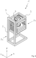
- the device 1 shows a device 1 according to the invention in a perspective representation.
- the device 1 comprises a base frame 2, which in the present case has frames which are connected to one another essentially at right angles and have rectangular tubes.
- the embodiment shown here is an example and represents only one possible embodiment for the base frame 2.
- Between two sides 2a, 2b of the base frame 2--having frames spaced apart from one another--a storage unit 3 is arranged, which serves to accommodate edge bands 4.
- the structure of the storage unit 3 is the same as that of the base frame 2, since this also has frames which are essentially connected to one another at right angles and have rectangular tubes.
- the storage unit 3 in the embodiment shown here by way of example fits within the internal dimensions of the base frame 2, with the storage unit 3 being positioned with its opposite sides 3a, 3b on the sides 2a, 2b of the Base frame 2 is guided linearly displaceable.
- the storage unit 3 is parallel to its own Pages 3a, 3b extending length constructed shorter than the base frame 2, so that they can be displaced relative to the base frame 2 within this with a corresponding stroke length a.
- rails 5 are arranged on the base frame 2 in a suitable manner.
- one of these rails 5 can be arranged on one of the opposite inner surfaces of the frames extending between the two sides 2a, 2b of the base frame 2, so that each of the sides 2a, 2b has two such rails 5.
- Areas of the storage unit 3 that correspond to these rails 5 ultimately enable their linear mobility relative to the base frame 2.
- the linear displacement of the storage unit 3 is preferably carried out by a drive that cannot be seen here; it can of course be done manually as an alternative or in addition to this.
- a look at the storage unit 3 makes it clear that it has a large number of support elements 6a, 6b arranged on its two sides 3a, 3b.
- the support elements 6a, 6b are designed like rails, which each extend perpendicularly to the length of the storage unit 3 on the two sides 2a, 2b of the base frame 2.
- the support elements 6a, 6b are arranged on the inner surfaces of the rectangular tubes of the frames located on each side 3a, 3b of the storage unit 3, as can be seen.
- the support elements 6a, 6b can be mounted on the sides 3a, 3b of the storage unit 3 so as to be linearly displaceable with respect to their lateral distance from one another in a manner that is not apparent.
- the support elements 6a, 6b divide the interior of the storage unit 3 into individual storage locations 7, with two opposing support elements 6a, 6b define a storage location 7.
- the storage locations 7 defined in this way serve to accommodate the edge bands 4, which in the present case are arranged at least in sections rolled up to form an edge roll within a cassette 4a.
- the cassettes 4a have side faces corresponding to the support elements 6a, 6b, which enable them to be pushed into and pulled out of the storage unit 3 accordingly.
- the individual storage locations 7 can also be defined by floor elements, which then extend at least partially between the sides 3a, 3b of the storage unit 3.
- the floor elements can be fixedly or slidably connected to the storage unit 3, so that they allow the pull-out of the storage unit 3 in the sense of a drawer.
- the floor elements allow edge bands 4 to be received directly, for example by being placed on the floor elements.
- the base elements can also be combined with the support elements 6a, 6b receiving the cassettes 4a.
- the support elements 6a, 6b are used to support floor elements, so that edge bands 4 can also be arranged directly in the storage unit 3 in this way.
- what was said above in relation to the support elements 6a, 6b can also apply to these floor elements, with regard to the possible change in distance between them due to a displaceable connection with the storage unit 3.
- the device 1 or the storage unit 3 can have a drive unit, not shown in detail, via which an edge band 4 can be actively driven at least in sections if required.
- the drive unit can either directly interact with the respective edge band 4 or with a cassette 4a containing the edge band 4.
- the device 1 or the storage unit 3 can have a brake unit, also not shown in detail, via which an edge band 4 can be braked and/or fixed with respect to its mobility.
- the braking unit can interact either directly with the respective edge band 4 or with a cassette 4a containing the edge band 4.
- the device 1 or the storage unit 3 can also have a cutting arrangement, also not shown in detail, by means of which a section of an edge band 4 can be separated.
- the cutting arrangement can interact either directly with the respective edge band 4 or with a cassette 4a containing the edge band 4.
- the drive unit or braking unit or cutting arrangement can also be at least part of a cassette 4 which can be controlled via a corresponding control of the device 1 or the storage unit 3 .
- a division into two would also be conceivable in that the cassettes 4a comprise the corresponding mechanical parts of the drive unit or braking unit or cutting arrangement, while the device 1 or the storage unit 3 have the corresponding drive for this, which can then be coupled to them.
- the device 1 can be aligned in such a way that its storage unit 3 - as in 1 can be seen - parallel to a vertical Z relative to the base frame 2 is linearly displaceable.
- the device 1 can of course also be used in an orientation rotated by 90°, so that its storage unit 3 can be linearly displaced parallel to a horizontal line X with respect to the base frame 2 .
- FIG. 2 shows the top view of an edging system 8, which includes an edging machine 9 and the device 1 explained in more detail above.
- the device 1 is located directly in front of the edging machine 9 in relation to a distance direction Y running at right angles to the horizontal X and the vertical Z.
- the device 1 is arranged in the area of the edging machine 8 in such a way that one of the edge bands 4 arranged in the device 1 is led directly out of the storage unit 3 of the device 1 into the edging machine 9 .
- the position of the device 1 is chosen so that the edge band 4 runs directly into an edge feed 9a of the edging machine 9, through which it is used in a manner not shown for edging panels, in particular wood-based panels.
- the storage location 7 of the device 1 stocked with the desired edging strip 4 was arranged in the plane of the edging supply 9a, in that its storage unit 3 was linearly displaced by a movement running parallel to the vertical Z in the present case.
- the edging system 8 can be designed in such a way that the device 1 can be displaced relative to the edging machine 9, which is related to the representation of FIG 2 their displacement in and against parallels Directions to the horizontal X and/or to the distance direction Y means.
- the device can be displaceable relative to the device 1 in a parallel direction running opposite to the distance direction Y, in order to be able to carry out any maintenance work.
- free access to the edge feed 9a is made possible.
- this mobility can also be used to move the device 1, for example, between two edging machines 9 spaced parallel to one another, as required, in order to be able to provide the required edging tape 4 on one or the other edging machine 9.
- Figures 3 to 7 each show expanded expansion stages of the device 1, through which its performance in relation to the provision of edge bands 4 can be increased.
- FIG 3 shows a first extended stage in which the device 1 is combined with a manipulator 10.
- An exemplary configuration of the manipulator 10 as a stacker crane (RBG) is shown here, which has a linear displaceability running parallel to the lifting direction of the device 1 .
- the manipulator 10 specifically has a lifting unit 10b which is mounted in a linearly movable manner in a frame 10a and which can accommodate at least one edging strip 4 or a cassette 4a fitted with an edging strip 4 .
- the manipulator 10 is used to equip the device 1 with edge bands 4 or with cassettes 4a each containing an edge band 4 and to empty the device 1. In this expansion stage, the manipulator 10 can be loaded manually.
- the manipulator 10 can be moved synchronously with the device 1 by means of a corresponding coupling. This coupling can take place mechanically and/or by means of control technology. Via a corresponding control of the manipulator 10, the device 1 can also be loaded and unloaded during operation.
- the storage arrangement 11 is in the present case like a shelving system with lateral support elements 11a in the form of rails, as already explained above for device 1, which have a large number of stacked slots 11b for edge bands 4 or cassettes 4a each containing an edge band 4.
- edgebands 4 that can be kept available in the storage arrangement 11 can now be removed individually or at least in pairs from this and transferred to the device 1, with the storage locations 7 of the storage unit 3 being stocked accordingly.
- the linearly displaceable lifting unit 10b of the manipulator 10 is moved into the required level of the storage arrangement 11, where it removes an edge band 4 or the cassette 4a containing the edge band 4 from the respective slot 11b. If necessary, the lifting unit 10b of the manipulator 10 then moves to another level in order to transfer the edgeband 4 or the cassette 4a to a free storage location 7 of the storage unit 3 of the device 1 . Of course, this can also be done in the opposite way, in order to feed edgebands 4 or cassettes 4a out of the device 1 to the storage arrangement 11 .
- FIG 5 illustrates the structure of a further expansion stage, which also includes a transfer device 12.
- the transfer device 12 is arranged on the device 1 in the present case, where it corresponds to a machine bearing 13 .
- the machine bearing 13 is located in a position that is not shown in detail Way above or directly on the edging machine 9.
- the storage arrangement 11 serves as a buffer for edging strips 4 or cassettes 4a, while the transfer device 12 preferably automatically supplies and removes new edging strips 4 or cassettes 4a.
- edge bands 4 or cassettes 4a that can be kept available in the machine storage 13 provided here, for example, close to the machine can be transferred to the manipulator 10 individually or at least in pairs.
- edge bands 4 or cassettes 4a arranged in the storage unit 3 and/or the storage arrangement 11 can be transferred individually or at least in pairs by the manipulator 10 to the transfer device 12 .
- FIG. 6 shows an expansion stage that is a doubling of the already in 4 structure shown includes.
- two devices 1 are provided here, each of which is combined with its own manipulator 10 and a storage arrangement 11 located on the respective manipulator 10 .
- This structure allows the two devices 1 to work alternately, which means that correspondingly high cycle rates can be achieved.
- the edging machine 9 has two edge feeds 9a (not shown in detail here) in order to be able to process the edge bands 4 of the respective device 1.
- FIG. 7 is a final possible expansion stage, which is a doubling of the already in figure 5 structure shown includes.
- two devices 1 are also provided here, each of which is combined with its own manipulator 10 and a storage arrangement 11 located on the respective manipulator 10, as well as a transfer device 12 and a machine bearing 13, in particular close to the machine. Again, the two devices 1 can work alternately to to achieve a high cycle rate for the edging of panels.
- the device 1 of all expansion stages can be equipped with at least one reading module, which is not shown in detail.
- the reading module can be arranged in the area of the storage unit 3 . It is also conceivable that each storage location 7 of the storage unit 3 is equipped with such a reading module.
- the goal is the automated transmission of information about the respective edge bands 4 or cassettes 4a, which are currently in the storage unit 3 or have been removed from it or have just been added.
- the edge bands 4 or cassettes 4a can be equipped with a corresponding transmission module on which the required information is stored.
- Such a transmission module can preferably contain at least one RFID chip or be designed as such.
- the reading module or the reading modules are set up to correspond with the transmission modules. This can be done in one direction or in both directions, which means the mere reading of data or a combination of reading and writing of data by the read module to a transmitter module.
- the device 1 according to the invention can advantageously include at least one interface, which is not shown in detail here. This interface is then designed to be coupled to at least one other component or machine, in particular mechanically and/or in a data-transmitting manner. In this way, all components or machines of an edging system 8 can be controlled via a corresponding controller.
- the frames located on one of the two sides 2a, 2b of the base frame 2 are connected to one another via two rectangular tubes extending between them parallel to the horizontal X.
- the visible base frame 2 has a total of four rectangular tubes connecting each of its two frames located on one side 2a, 2b and extending parallel to the horizontal X between the opposite corners of said frames.
- those rectangular tubes connecting the frames lie one above the other in relation to the vertical Z, so that the base frame 2 is essentially U-shaped in its plan view, which is not shown in detail here.
- the base frame 2 manages with a frame located on only one side 2a, while the opposite side 2b is virtually frameless.
- the lower area of the base frame 2 which is made up of rectangular tubes, is designed to be closed.
- the two rectangular tubes running parallel to the horizontal X each extend from a lower corner of the side 2a located frame away, these being connected to one another at the ends via a rectangular tube running parallel to the spacing direction Y.
Description
Die Erfindung betrifft eine Bekantungsanlage umfassend eine Bekantungsmaschine und eine Vorrichtung zur Bereitstellung von Kantenbändern gemäß dem Oberbegriff von Anspruch 1. Weiterhin ist die Erfindung auf eine Verwendung einer Bekantungsanlage nach einem der vorigen Ansprüche gerichtet Eine solcheThe invention relates to an edging system comprising an edging machine and a device for preparing edge bands according to the preamble of
Bekantungsanlage ist vom Dokument
Platten aus Holz- oder Holzersatzstoffen für die Möbelindustrie weisen üblicherweise bereits vor ihrer Verarbeitung wenigstens eine zumindest teilweise beschichtete Deckfläche auf. Die Arten dieser Beschichtungen reichen von Lackierungen bis hin zu Verkleidungen mit Lagen aus Echtholzfurnier oder Kunststoff. Neben der jeweiligen Optik besitzen die so beschichteten Oberflächen eine erhöhte Beständigkeit gegenüber mechanischen Einwirkungen und Flüssigkeiten. Die Beschichtung der schmalen Randseiten dieser Platten erfolgt gewöhnlich erst im Nachgang, wie etwa nach deren Zuschnitt. Im Rahmen der sogenannten Bekantung wird dabei zumindest abschnittsweise ein passendes Kantenband an den Schmalseiten der Platte angebracht. Deren Verbund mit der Platte basiert in der Regel auf Adhäsion oder einem Mikroformschluss durch lokales Anschmelzen.Boards made of wood or wood substitutes for the furniture industry usually have at least one at least partially coated top surface before they are processed. The types of these coatings range from lacquer finishes to paneling with layers of real wood veneer or plastic. In addition to the respective appearance, the surfaces coated in this way have increased resistance to mechanical influences and liquids. The narrow edges of these panels are usually only coated afterwards, for example after they have been cut to size. As part of the so-called edging, a suitable edge band is attached to the narrow sides of the panel at least in sections. Their bond with the panel is usually based on adhesion or a micro form fit through local melting.
Im industriellen Rahmen erfolgt die Bekantung von Holzwerkstoffplatten durch eine Bekantungsanlage, in der die Kantenbänder mit wenigstens einer Bekantungsmaschine im Durchlaufverfahren angebracht werden. Üblicherweise liegen die Kantenbänder dabei in aufgerollter Form als Kantenrollen vor, um so auch große Längen auf möglichst kompakte Weise sicher transportieren und lagern zu können. Für eine möglichst einfache Handhabung können diese auch innerhalb einer Kassette angeordnet und bei Bedarf aus dieser abspulbar sein. Aufgrund der Vielfalt an Farben und Dekoren sowie Dicken (Stärke) der zu bekantenden Platten müssen die dann ebenfalls unterschiedlichen Kantenbänder oftmals gegen die jeweils passende Variante ausgewechselt werden.In the industrial context, the edging of wood-based panels is carried out by an edging system in which the edge bands are attached with at least one edging machine in a continuous process. The edgebands are usually lying rolled up as edge rolls in order to be able to safely transport and store large lengths in the most compact way possible. For the simplest possible handling, these can also be arranged within a cassette and can be unwound from this if necessary. Due to the variety of colors and decors as well as thicknesses (thickness) of the panels to be edged, the edge bands, which are then also different, often have to be replaced with the appropriate variant.
Aus
In der konkreten Ausgestaltung dient ein Lagerplatz der Aufbewahrungseinheit als feste Wechselplatzposition, welche mit einem außen an der Aufbewahrungseinheit angeordneten und auf derselben Höhe gelegenen Einlagerungstisch korrespondiert. Von dem Einlagerungstisch aus ist eine mit einer Kantenrolle bestückte Kassette händisch in die Wechselplatzposition einführbar. Anschließend wird diese Kassette von einer auf der gegenüberliegenden Seite der Aufbewahrungseinheit angeordneten Handhabungseinrichtung in einen anderen Lagerplatz innerhalb der Aufbewahrungseinheit einsortiert. Umgekehrt wird eine auszutauschende Kassette zunächst mittels der Handhabungseinrichtung aus ihrem Lagerplatz innerhalb der Aufbewahrungseinheit herausgezogen und in die Wechselplatzposition überführt, von wo aus sie wieder händisch entfernt und beispielsweise zum Einlegen einer neuen Kantenrolle auf dem Einlagerungstisch abgelegt wird. Die Versorgung einer Bekantungsmaschine mit Kantenbändern erfolgt über die Handhabungseinrichtung der Vorrichtung, welche hierfür die jeweils benötigte Kassette aus der Aufbewahrungseinheit entnimmt und an die Bekantungsmaschine übergibt.In the specific embodiment, a storage place of the storage unit serves as a fixed changing place position, which corresponds to a storage table that is arranged on the outside of the storage unit and is at the same height. A cassette fitted with an edge roll can be inserted manually into the changing position from the storage table. This cassette is then sorted into another storage location within the storage unit by a handling device arranged on the opposite side of the storage unit. Conversely, a cassette to be exchanged is first pulled out of its storage location within the storage unit by means of the handling device and transferred to the exchange location position, from where it is manually removed again and placed on the storage table, for example to insert a new edge roll. An edging machine is supplied with edgebands via the handling device of the device, which removes the required cassette from the storage unit and transfers it to the edging machine.
Insbesondere der Wechsel zwischen unterschiedlichen Kantenbändern beziehungsweise den diese enthaltenden Kassetten gestaltet sich mitunter aufwendig. Ursächlich hierfür ist die stets notwendige Zwischenschaltung der Handhabungseinrichtung, die sowohl für die Verteilung der Kantenbänder innerhalb der Aufbewahrungseinheit als auch für die Versorgung der Bekantungsmaschine mit den jeweils benötigten Kantenbändern erforderlich ist. Neben einer umfangreichen Wartung benötigen die zu koordinierenden Bewegungen der Handhabungseinrichtung einen entsprechend hohen Zeit- und Steuerungsaufwand.In particular, changing between different edge bands or the cassettes containing them is sometimes complicated. The reason for this is the always necessary interposition of the handling device, which is required both for the distribution of the edge bands within the storage unit and for the supply of the edging machine with the required edge bands. In addition to extensive maintenance, the movements of the handling device to be coordinated require a correspondingly high expenditure of time and control.
Der vorliegenden Erfindung liegt daher die Aufgabe zugrunde, eine gattungsgemäße Vorrichtung sowie eine damit ausgestattete Bekantungsanlage dahingehend weiterzuentwickeln, dass die Bereitstellung von Kantenbändern insgesamt wirtschaftlicher erfolgen kann.The present invention is therefore based on the object of further developing a generic device and an edging system equipped therewith such that the provision of edging strips can take place more economically overall.
Die Lösung dieser Aufgabe besteht nach der Erfindung in einer Bekantungsanlage, umfassend eine Bekantungsmaschine und wenigstens eine Vorrichtung zur Bereitstellung von Kantenbändern gemäß Anspruch 1. Vorteilhafte Ausgestaltungen sind Gegenstand der jeweils abhängigen Unteransprüche 2 bis 13.According to the invention, this object is achieved in an edging system comprising an edging machine and at least one device for preparing edge bands according to
So wird vorgeschlagen, dass die Vorrichtung ein Grundgestell umfassen soll, wobei die eigentliche Aufbewahrungseinheit nunmehr in oder an diesem Grundgestell linear verlagerbar angeordnet ist. Mit anderen Worten kann die erfindungsgemäße Vorrichtung über ihr Grundgestell auf einem Untergrund aufstehen und/oder an einer anderen Komponente befestigt sein, während die zur Aufnahme von Kantenbändern ausgebildete Aufbewahrungseinheit relativ zum Grundgestell linear verlagerbar ist.It is proposed that the device should include a base frame, with the actual storage unit now being arranged in or on this base frame in a linearly displaceable manner. In other words, the device according to the invention stand up on a base via its base frame and/or be attached to another component, while the storage unit designed to accommodate edge bands can be linearly displaced relative to the base frame.
Der sich hieraus unmittelbar ableitende Vorteil ist darin zu sehen, dass die erfindungsgemäße Ausgestaltung keinerlei Umschichtung von Kantenbändern beziehungsweise Kassetten innerhalb der Aufbewahrungseinheit erfordert, da das jeweils benötigte Kantenband unabhängig von seiner Anordnung in einem der Lagerplätze allein aufgrund der linearen Beweglichkeit der Aufbewahrungseinheit in die erforderliche Ebene gegenüber einer Bekantungsmaschine verlagerbar ist. Auf diese Weise kann die zur bisher erforderlichen Verteilung von Kantenbändern innerhalb der Aufbewahrungseinheit benötigte Handhabungseinrichtung entfallen. Überdies besteht keine zwingende Notwendigkeit mehr für eine Übergabe des jeweiligen Kantenbands an eine Bekantungsmaschine, da dieses nun direkt aus der Aufbewahrungseinheit heraus zugeführt werden kann, indem der das benötigte Kantenband enthaltende Lagerplatz zuvor beispielsweise gegenüber einer Kantenzufuhr der Bekantungsmaschine positionierbar ist.The advantage directly derived from this can be seen in the fact that the configuration according to the invention does not require any rearrangement of edge bands or cassettes within the storage unit, since the edge band required in each case, regardless of its arrangement in one of the storage locations, is in the required level solely due to the linear mobility of the storage unit can be displaced in relation to an edging machine. In this way, the handling device required for the previously required distribution of edge bands within the storage unit can be omitted. In addition, there is no longer a compelling need to transfer the respective edge band to an edging machine, since this can now be fed directly from the storage unit, in that the storage space containing the required edging band can be positioned beforehand, for example opposite an edge feed of the edging machine.
Nach einer besonders bevorzugten Weiterbildung des grundsätzlichen Erfindungsgedankens kann wenigstens ein Lagerplatz der Aufbewahrungseinheit so ausgebildet sein, dass dieser wenigstens ein Kantenband aufnehmen kann. Mit anderen Worten kann dieser Lagerplatz so ausgestaltet sein, dass ein loses Kantenband, insbesondere in dessen zumindest abschnittsweise zu einer Kantenrolle aufgewickelten Form, in diesem anordenbar beziehungsweise ablegbar ist. Alternativ oder ergänzend hierzu kann wenigstens einer der Lagerplätze zur Aufnahme einer das Kantenband zumindest teilweise enthaltenden Kassette ausgebildet sein.According to a particularly preferred development of the basic idea of the invention, at least one storage location of the storage unit can be designed in such a way that it can accommodate at least one edge band. In other words, this storage location can be designed in such a way that a loose edging strip, in particular in its form at least partially wound up to form an edging roll, can be arranged or stored in it. As an alternative or in addition to this, at least one of the storage locations can be designed to accommodate a cassette that at least partially contains the edging strip.
Die Aufbewahrungseinheit weist zwei gegenüberliegende Seiten auf, wobei die Ausgestaltung ihrer Lagerplätze in vorteilhafter Weise an die Form der aufzunehmenden Kantenbänder angepasst sein kann. So kann wenigstens einer der Lagerplätze mindestens ein sich zumindest teilweise zwischen den Seiten der Aufbewahrungseinheit erstreckendes Bodenelement besitzen. Dieses kann beispielsweise so ausgestaltet sein, dass ein Kantenband direkt auf diesem Bodenelement ablegbar oder zumindest teilweise an diesem abstützbar ist. Alternativ oder ergänzend hierzu kann zumindest einer der Lagerplätze mindestens ein im Bereich jeder Seite der Aufbewahrungseinheit angeordnetes Stützelement besitzen. Die Stützelemente können beispielsweise so ausgestaltet sein, dass eine ein Kantenband enthaltende Kassette auf diesen Stützelementen ablegbar oder zumindest teilweise an diesem abstützbar ist.The storage unit has two opposite sides, and the design of its storage locations can advantageously be adapted to the shape of the edge bands to be accommodated. Thus, at least one of the storage locations can have at least one floor element that extends at least partially between the sides of the storage unit. This can, for example, be designed in such a way that an edge band can be placed directly on this floor element or at least partially supported on it. As an alternative or in addition to this, at least one of the storage locations can have at least one support element arranged in the area of each side of the storage unit. The support elements can, for example, be designed in such a way that a cassette containing an edge band can be placed on these support elements or at least partially supported on them.
In diesem Zusammenhang sieht die Erfindung gemäß einer bevorzugten Weiterentwicklung vor, dass das Bodenelement und/oder mindestens ein Stützelement wenigstens eines Lagerplatzes an der Aufbewahrungseinheit linear verschieblich gelagert ist. Durch eine entsprechende Verlagerung des so verschieblichen Bodenelements und/oder Stützelements ist insbesondere die zur Aufnahme eines Kantenbands oder einer das Kantenband enthaltenden Kassette verfügbare Höhe des zugehörigen Lagerplatzes an die jeweils benötigte Höhe anpassbar. Konkret kann so eine Anpassung an unterschiedliche Breiten aufweisende Kantenbänder beziehungsweise Höhen ihrer Kassetten vorgenommen werden. Hierdurch kann der jeweilige Lagerplatz möglichst spielfrei in Bezug auf das aufzunehmende Kantenband angepasst werden. Denkbar ist auch eine so mögliche Anpassung der Anzahl an Lagerplätzen, welche sich beispielsweise durch deren Anpassung an entsprechend dünne Kantenbänder um einen oder gar mehrere Plätze erhöhen lässt.In this connection, according to a preferred further development, the invention provides that the floor element and/or at least one support element of at least one storage location is mounted on the storage unit so that it can be displaced in a linear manner. By appropriately shifting the base element and/or support element that can be displaced in this way, the height of the associated storage space available for receiving an edge band or a cassette containing the edge band can be adapted to the respectively required height. Specifically, an adaptation to edge bands having different widths or heights of their cassettes can be carried out in this way. As a result, the respective storage location can be adjusted with as little play as possible in relation to the edge band to be picked up. It is also conceivable to adjust the number of storage locations in this way, which can be increased by one or even more locations, for example by adapting them to correspondingly thin edge bands.
Nach einer besonders bevorzugten Weiterbildung der Erfindung kann die Aufbewahrungseinheit oder jeder Lagerplatz der Aufbewahrungseinheit mit wenigstens einem Lesemodul ausgestattet sein. In vorteilhafter Weise kann es sich dabei um ein sogenanntes berührungsloses Lesemodul handeln, welches übermittelte Daten dann entsprechend kabellos empfangen kann. In jedem Fall ist das Lesemodul dazu eingerichtet, mit wenigstens einem Sendemodul eines Kantenbands oder einer das Kantenband enthaltenden Kassette zu korrespondieren. Hierzu kann beispielsweise ein RFID-Chip in oder an einem Kantenband beziehungsweise dessen Kassette angeordnet sein, welcher über eine entsprechende äußere Anregung die in ihm abgelegten Daten an das Lesemodul überträgt. Auf diese Weise sind benötigte Informationen über das in einem der Lagerplätze anzuordnenden Kantenband an die Vorrichtung übermittelbar, die dann zur Ansteuerung der Aufbewahrungseinheit genutzt werden können. Die Informationen können beispielsweise Angaben über die Breite und das Dekor beziehungsweise die Farbe des jeweiligen Kantenbands enthalten. Auf diese Weise ist es beispielsweise möglich, dass die Vorrichtung und/oder eine diese ansteuernde Steuerung über in der Aufbewahrungseinheit vorgehaltene Kantenbänder und deren jeweiligen Lagerplatz quasi in Kenntnis ist, um so das jeweils angeforderte beziehungsweise benötigte Kantenband zur Verfügung stellen zu können.According to a particularly preferred development of the invention, the storage unit or each storage location of the storage unit can be equipped with at least one reading module. Advantageously, this can be a so-called contactless reading module, which can then correspondingly wirelessly receive transmitted data. In any case, the reading module is set up to correspond with at least one transmission module of an edge band or a cassette containing the edge band. For this purpose, for example, an RFID chip can be arranged in or on an edge band or its cassette, which transmits the data stored in it to the reading module via a corresponding external stimulus. In this way, required information about the edgeband to be arranged in one of the storage locations can be transmitted to the device, which can then be used to control the storage unit. The information can contain, for example, information about the width and the decor or the color of the respective edge band. In this way, it is possible, for example, for the device and/or a controller that activates it to know more or less about the edge bands kept in the storage unit and their respective storage location, in order to be able to provide the requested or required edge band.
Denkbar ist, dass das Lesemodul selbst oder ein zusätzliches Bauteil eine Sendeeinheit enthält, die wiederum Informationen an das dann beispielsweise hierüber beschreibbare Sendemodul des jeweiligen Kantenbands übermitteln kann. Hierdurch können beispielsweise Angaben über die verbliebene Länge des Kantenbands in dessen Sendemodul hinterlegt werden, so dass stets auf solche Kantenbänder zurückgegriffen wird, die eine für die bevorstehende Bekantung erforderliche Restlänge aufweisen. Insbesondere mit Blick auf eine bevorzugt automatisierte Ansteuerung der Vorrichtung wird es als besonders vorteilhaft angesehen, wenn die Vorrichtung einen Antrieb aufweist, durch den die Aufbewahrungseinheit entsprechend selbsttätig gegenüber dem Grundgestell verlagerbar ist. Alternativ oder ergänzend hierzu kann auch eine manuelle Verlagerbarkeit der Aufbewahrungseinheit gegenüber dem Grundgestell der Vorrichtung vorgesehen sein. So kann eine in ihrer Ausbaustufe eher einfache Vorrichtung die manuelle Verlagerung ihrer Aufbewahrungseinheit erfordern, während deren höhere Ausbaustufe einen entsprechend angesteuerten Antrieb vorsieht. Grundsätzlich kann auch eine mit einem solchen Antrieb ausgestattete Vorrichtung die manuelle Verlagerbarkeit ihrer Aufbewahrungseinheit ermöglichen, um Wartungsarbeiten zu erleichtern und/oder um beispielsweise auch bei einem Defekt des Antriebs die Einsetzbarkeit der Vorrichtung durch manuelle Handhabung gewährleisten zu können.It is conceivable that the reading module itself or an additional component contains a transmission unit, which in turn can transmit information to the transmission module of the respective edge band, which can then be written to, for example. In this way, for example, information about the remaining length of the edge band can be stored in its transmission module, so that edge bands that have a remaining length required for the forthcoming edging can always be used. In particular with regard to a preferably automated control of the device, it is considered to be particularly advantageous if the device has a drive, by means of which the storage unit can be correspondingly and automatically displaced relative to the base frame. As an alternative or in addition to this, it is also possible for the storage unit to be moved manually relative to the base frame of the device. A device that is rather simple in its expansion stage can thus require the manual relocation of its storage unit, while its higher expansion stage provides for a correspondingly controlled drive. In principle, a device equipped with such a drive can also allow its storage unit to be moved manually in order to facilitate maintenance work and/or to be able to ensure the usability of the device by manual handling even in the event of a defect in the drive.
Die erfindungsgemäße Vorrichtung kann eine Schnittstelle besitzen, welche mit mindestens einer weiteren Komponente oder Maschine koppelbar ist. Die Schnittstelle kann grundsätzlich eine mechanische und/oder datenübertragende Kopplung ermöglichen. Hierdurch ist beispielsweise eine einfache Integration in bestehende Anlagenstrukturen und deren Ablaufprozesse gegeben, da aus der bestehenden Anlage beziehungsweise deren Steuerung zur Verfügung stehende Signale über die Schnittstelle an die Vorrichtung übermittelbar und/oder Signale von der Vorrichtung an die bestehenden Anlage beziehungsweise deren Steuerung weitergegeben werden können.The device according to the invention can have an interface which can be coupled to at least one other component or machine. In principle, the interface can enable a mechanical and/or data-transmitting coupling. This allows, for example, simple integration into existing system structures and their operational processes, since signals available from the existing system or its controller can be transmitted via the interface to the device and/or signals can be forwarded from the device to the existing system or its controller .
Nach einer vorteilhaften Ausgestaltung der Erfindung kann die Vorrichtung wenigstens eine Antriebseinheit besitzen, über die ein Kantenband wenigstens abschnittsweise aktiv antreibbar ist. Dies meint, dass ein freies Ende des Kantenbands beispielsweise aus seiner Anordnung innerhalb der Aufbewahrungseinheit heraus und möglicherweise auch darüber hinaus verlagerbar sein kann. Auf diese Weise kann die Antriebseinheit das Kantenband aus seinem Lagerplatz heraus an eine Bekantungsmaschine zumindest übergeben. Auch kann das Nachführen des Kantenbands in die Bekantungsmaschine hinein vollständig über die Antriebseinheit erfolgen oder durch diese wenigstens unterstützt werden. In der konkreten Ausgestaltung wären hierzu beispielsweise eine aktive Rotation des aufgewickelten Kantenbands und/oder wenigstens ein Reibrad denkbar, welches einen umfangsseitigen Kontakt zum Kantenband aufweist und dieses durch eine Rotation zumindest abschnittsweise antreibt beziehungsweise abspult. Grundsätzlich kann die Antriebseinheit dabei mit einem zumindest teilweise innerhalb einer Kassette angeordneten oder einem ohne eine solche vorliegenden Kantenband zusammenwirken.According to an advantageous embodiment of the invention, the device can have at least one drive unit, via which an edge band can be actively driven at least in sections. This means that a free end of the edge band, for example can be displaceable from its location within the storage unit and possibly also beyond. In this way, the drive unit can at least transfer the edgeband from its storage location to an edging machine. The tracking of the edging tape into the edging machine can also take place entirely via the drive unit or at least be supported by it. In the specific embodiment, for example, an active rotation of the wound edge band and/or at least one friction wheel would be conceivable, which has peripheral contact with the edge band and at least partially drives or unwinds this by rotating. In principle, the drive unit can interact with an edge band that is at least partially arranged within a cassette or with an edge band that is present without such a cassette.
Die Vorrichtung kann in bevorzugter Weise wenigstens eine Bremseinheit besitzen, über welche ein Kantenband gegenüber seiner Beweglichkeit abbremsbar und/oder fixierbar ist. Als Beweglichkeit des Kantenbands wird sowohl sein kontrollierter Antrieb als auch sein unkontrolliertes Bewegungsverhalten angesehen, welches insbesondere auf Spannungen innerhalb seines Materials zurückzuführen ist, welche sich aus dem aufgerollten Zustand und/oder Temperaturschwankungen ergeben können/kann. Selbstverständlich zählen auch alle weiteren, eine Bewegung des Kantenbands hervorrufenden Einflüsse hierzu, wie etwa Erschütterungen. Die Bremseinheit ist so ausgelegt, dass sie die beispielsweise durch Ziehen an einem Abschnitt des Kantenbands erfolgende Bewegung desselben zumindest bremst. Bevorzugt kann die Bremseinheit das Kantenband derart fixieren, dass stets eine Kontrolle über dessen freies Ende gewährleistet ist. Hierdurch kann dem selbständigen Zurückziehen oder Verlagern des freien Endes des Kantenbands begegnet werden, indem dieses durch die Bremseinheit quasi gehalten ist. Die Bremseinheit kann dabei grundsätzlich mit einem zumindest teilweise innerhalb einer Kassette angeordneten oder einem ohne eine solche vorliegenden Kantenband zusammenwirken.The device can preferably have at least one brake unit, via which an edge band can be braked and/or fixed with respect to its mobility. Both its controlled drive and its uncontrolled movement behavior are considered to be mobility of the edgeband, which can be attributed in particular to tensions within its material, which can/can result from the rolled-up state and/or temperature fluctuations. Of course, this also includes all other influences that cause movement of the edgeband, such as vibrations. The brake unit is designed in such a way that it at least brakes the movement of the same, which occurs, for example, by pulling on a section of the edge band. The brake unit can preferably fix the edge band in such a way that control over its free end is always ensured. This can prevent the free end of the edge band from being pulled back or displaced on its own be by this is quasi held by the brake unit. In principle, the brake unit can interact with an edge band that is at least partially arranged within a cassette or with an edge band that is present without such a cassette.
Die Erfindung sieht vor, dass die Vorrichtung eine Schneidanordnung aufweisen kann, durch welche ein Abschnitt eines Kantenbands bedarfsweise abtrennbar ist. So kann beispielsweise nur ein Kantenbandabschnitt an eine Bekantungsmaschine überführt werden, dessen im Verlauf durch die Schneidanordnung abgetrennte Länge der zu verarbeitenden Länge entspricht. Die Schneidanordnung kann dabei grundsätzlich mit einem zumindest teilweise innerhalb einer Kassette angeordneten oder einem ohne eine solche vorliegenden Kantenband zusammenwirken.The invention provides that the device can have a cutting arrangement, by means of which a section of an edge band can be separated as required. For example, only one edgeband section can be transferred to an edging machine, the length of which, cut off by the cutting arrangement, corresponds to the length to be processed. In principle, the cutting arrangement can interact with an edge band that is at least partially arranged within a cassette or with an edge band that is present without such a cassette.
Im Rahmen der Erfindung ist denkbar, dass sich die Vorrichtung in ihrer bestimmungsgemäßen Anordnung entweder vertikal oder horizontal erstreckt. So ist erfindungsgemäß deren Aufbewahrungseinheit entsprechend parallel zu einer Vertikalen oder aber parallel zu einer Horizontalen gegenüber dem Grundgestell linear verlagerbar. Je nach Anwendungsfall ergeben sich hierdurch vorteilhafte Möglichkeiten zur Nutzung des zur Verfügung stehenden Bauraums.It is conceivable within the scope of the invention for the device to extend either vertically or horizontally in its intended arrangement. According to the invention, its storage unit can be displaced linearly in relation to the base frame parallel to a vertical line or parallel to a horizontal line. Depending on the application, this results in advantageous options for using the available installation space.
Da die Anzahl der in Bezug auf eine vertikale Ausrichtung übereinanderliegenden Lagerplätze der dabei vertikal verlagerbaren Aufbewahrungseinheit bereits durch die jeweilige Deckenhöhe naturgemäß begrenzt ist, kann diese durch eine demgegenüber horizontale Orientierung der Aufbewahrungseinheit entsprechend vergrößert werden. Insbesondere die Höhenlage der Kantenzufuhr an einer Bekantungsmaschine limitiert die zum direkten Abspulen eines Kantenbands aus seinem Lagerplatz heraus maximal mögliche Höhe der Aufbewahrungseinheit, da deren oberster Lagerplatz hierfür in der Ebene der Kantenzufuhr liegen muss. Folglich ergibt sich die Anzahl der maximal möglichen Lagerplätze durch den unterhalb dieser Ebene zur Verfügung stehenden Platz. Etwaige Vertiefungen im Untergrund erlauben hierbei selbstverständlich größere Höhen für die Aufbewahrungseinheit, da diese in ihrer maximal abgesenkten Lage dann zumindest abschnittsweise in eine solche Vertiefung verlagerbar wäre.Since the number of storage locations one above the other in relation to a vertical orientation of the vertically displaceable storage unit is naturally already limited by the respective ceiling height, this can be correspondingly increased by a horizontal orientation of the storage unit. In particular, the height of the edging feed on an edging machine limits the maximum possible height of the storage unit for directly unwinding an edging strip from its storage location, since its uppermost storage space for this is in the level of the edging feed must lie. Consequently, the maximum number of possible storage locations results from the space available below this level. Any indentations in the subsoil naturally permit greater heights for the storage unit, since in its maximally lowered position it would then be displaceable, at least in sections, into such an indentation.
Der Vorteil einer vertikalen Orientierung der Vorrichtung liegt darin, dass in dieser vorgehaltene Kantenbänder in der Regel ohne eine Drehung um ihre Längsachse in eine Bekantungsmaschine einlaufen können. Maßgeblich hierfür ist deren dabei in Bezug auf ihren Querschnitt stehende Orientierung, die parallel zu den üblicherweise liegend verarbeiteten Holzwerkstoffplatten verläuft. Demgegenüber erfordert eine horizontale Orientierung der Vorrichtung dabei eine um 90° notwendige Drehung eines Kantenbands um dessen Längsachse, um dieses in Bezug auf seinen Querschnitt dann liegend innerhalb der Aufbewahrungseinheit vorliegende Kantenband parallel zu den schmalen Randseiten einer Holzwerkstoffplatte auszurichten. Insbesondere die Drehung eines Kantenbands um seine Längsrichtung kann dessen Struktur belasten. Auf der anderen Seite erlaubt die horizontale Orientierung der Vorrichtung eine größere Länge seiner Aufbewahrungseinheit, so dass diese entsprechend mehr Lagerplätze für Kantenbänder zur Verfügung stellt. Die vorteilhaftere Orientierung der Vorrichtung ist anhand der genannten Kriterien seitens des zuständigen Fachmanns im jeweiligen Einzelfall auszuwählen.The advantage of a vertical orientation of the device lies in the fact that edge bands held in this device can generally run into an edging machine without rotating about their longitudinal axis. The decisive factor here is their orientation in relation to their cross section, which runs parallel to the wood-based panels that are usually processed lying flat. In contrast, a horizontal orientation of the device requires a 90° rotation of an edge band about its longitudinal axis in order to align this edge band lying within the storage unit in relation to its cross section parallel to the narrow edge sides of a wood-based panel. In particular, the rotation of an edge band around its longitudinal direction can stress its structure. On the other hand, the horizontal orientation of the device allows a greater length of its storage unit, so that it provides correspondingly more storage space for edge bands. The more advantageous orientation of the device is to be selected on the basis of the criteria mentioned by the person skilled in the art in each individual case.
Gemäß einer bevorzugten Weiterbildung kann die Vorrichtung wenigstens einen Manipulator umfassen. Bei diesem Manipulator kann es sich beispielsweise um einen mehrachsigen Roboterarm und/oder ein Regalbediengerät (RBG) handeln. Der Manipulator ist so angeordnet und eingerichtet, dass dieser jeden Lagerplatz der Aufbewahrungseinheit erreicht. Auf diese Weise kann der Manipulator dazu dienen, die Lagerplätze mit Kantenbändern zu bestücken und zu entleeren, indem die Kantenbänder bedarfsweise aus den Lagerplätzen herausgenommen werden. Selbstverständlich ist dies unabhängig davon, ob die jeweiligen Kantenbänder als solche vorliegen oder zumindest teilweise innerhalb einer Kassette angeordnet sind. Gegenüber einer händischen Bestückung sowie Entnahme der Kantenbänder ermöglicht der Manipulator eine weitergehende Automatisierung der Vorrichtung.According to a preferred development, the device can include at least one manipulator. This manipulator can be, for example, a multi-axis robotic arm and/or a stacker crane (SRM). The manipulator is arranged and set up in such a way that each storage location of the storage unit. In this way, the manipulator can be used to load and empty the storage locations with edge bands by removing the edge bands from the storage locations as required. Of course, this is independent of whether the respective edge bands are present as such or are at least partially arranged within a cassette. Compared to manual assembly and removal of the edge bands, the manipulator enables further automation of the device.
Im Zusammenhang mit dem wenigstens einen Manipulator ist vorgesehen, dass die erfindungsgemäße Vorrichtung zudem eine Speicheranordnung besitzen kann. Die Speicheranordnung dient der lokalen Vorhaltung von Kantenbändern beziehungsweise Kantenbänder enthaltenden Kassetten. Mit Hilfe des Manipulators sind diese dann einzeln oder wenigstens zu zweit aus der Speicheranordnung entnehmbar und an die Aufbewahrungseinrichtung der Vorrichtung überführbar. Auf diese Weise sind die Lagerplätze der Aufbewahrungseinheit aus der Speicheranordnung heraus einzeln mit Kantenbändern bestückbar. Umgekehrt dient die Speicheranordnung der lokalen Vorhaltung von Kantenbändern beziehungsweise Kantenbänder enthaltenden Kassetten, die durch den Manipulator einzeln oder wenigstens zu zweit aus der Aufbewahrungseinrichtung heraus entnehmbar sind, um daraufhin zur Speicheranordnung überführt zu werden.In connection with the at least one manipulator, it is provided that the device according to the invention can also have a storage arrangement. The storage arrangement is used for the local provision of edge bands or cassettes containing edge bands. With the help of the manipulator, these can then be removed individually or at least in pairs from the storage arrangement and transferred to the storage device of the device. In this way, the storage locations of the storage unit can be equipped individually with edge bands from the storage arrangement. Conversely, the storage arrangement is used for the local provision of edge bands or cassettes containing edge bands, which can be removed from the storage device individually or at least in pairs by the manipulator in order to then be transferred to the storage arrangement.
Durch die Kombination aus Speicheranordnung und Manipulator lässt sich die Anzahl der lokal vorhaltbaren Kantenbänder entsprechend erhöhen, was kürzere Reaktionszeiten und/oder eine höhere Auswahl voneinander unterschiedlicher Kantenbänder ermöglicht.The combination of storage arrangement and manipulator allows the number of edge bands that can be kept locally to be increased accordingly, which enables shorter reaction times and/or a greater selection of edge bands that differ from one another.
Gemäß einer auf dem Vorhandensein eines Manipulators basierenden weiteren Ausbaustufe der erfindungsgemäßen Vorrichtung kann zusätzlich eine Übergabeeinrichtung vorgesehen sein, durch die auf weitere, in einem in der Nähe gelegenen Maschinenlager vorgehaltene Kantenbänder zurückgegriffen werden kann. So sind in dem Maschinenlager befindliche Kantenbänder einzeln oder wenigstens zu zweit durch die Übergabeeinrichtung entnehmbar und an den Manipulator übergebbar, die anschließend an die Speicheranordnung und/oder die Aufbewahrungseinheit weitergebbar sind. Umgekehrt können in der Speicheranordnung und/oder der Aufbewahrungseinheit befindliche Kantenbänder einzeln oder wenigstens zu zweit durch den Manipulator entnommen und an die Übergabeeinrichtung weitergereicht werden, von wo aus sie zurück in das Maschinenlager überführbar sind.According to a further expansion stage of the device according to the invention based on the presence of a manipulator A transfer device can also be provided, which can be used to access other edgebands stored in a nearby machine store. Edge bands located in the machine storage can be removed individually or at least in pairs by the transfer device and transferred to the manipulator, which can then be transferred to the storage arrangement and/or the storage unit. Conversely, edge bands located in the storage arrangement and/or the storage unit can be removed individually or at least in pairs by the manipulator and passed on to the transfer device, from where they can be transferred back to the machine store.
Die nunmehr vorgestellte erfindungsgemäße Vorrichtung ermöglicht eine insgesamt überaus wirtschaftliche Bereitstellung von Kantenbändern. Insbesondere die lineare Verlagerbarkeit der mit Kantenbändern bestückbaren Aufbewahrungseinheit liefert den entscheidenden Beitrag dazu, ein Kantenband quasi ungeordnet in einen der freien Lagerplätze abzulegen. Bei Bedarf kann dieser durch eine einfache Verlagerung der gesamten Aufbewahrungseinheit in die erforderliche Ebene gegenüber einer Bekantungsmaschine gebracht werden, um auf das darin befindliche Kantenband zugreifen zu können. Eine vorherige, insbesondere mechanische, Sortierung der Kantenbänder ist insofern nicht mehr nötig. Dies basiert auf der Kenntnis von Daten über die in der Aufbewahrungseinheit vorgehaltenen Kantenbänder, welche sich aus der zumindest in eine Richtung möglichen Kommunikation zwischen der Vorrichtung und dem jeweiligen Kantenband oder der das Kantenband enthaltenen Kassette ergeben. Über eine entsprechende Steuerung ist so stets das aktuell benötigte Kantenband in Ebene der Kantenzufuhr der Bekantungsmaschine positionierbar, um in die Bekantungsmaschine einzulaufen. Durch weitere Ausbaustufen, wie etwa wenigstens einen Manipulator und eine Speicheranordnung für Kantenbänder, lässt sich die Effizienz der Vorrichtung durch Erhöhung ihrer Vorhaltekapazität weiter steigern.The device according to the invention that has now been presented enables edgebands to be provided in an overall extremely economical manner. In particular, the linear displaceability of the storage unit that can be fitted with edgebands makes a decisive contribution to storing an edgeband in one of the free storage locations in a quasi-disordered manner. If necessary, this can be brought to the required level in relation to an edging machine by simply moving the entire storage unit in order to be able to access the edging tape contained therein. A previous, in particular mechanical, sorting of the edge bands is no longer necessary. This is based on the knowledge of data about the edge bands held available in the storage unit, which result from the communication that is possible at least in one direction between the device and the respective edge band or the cassette containing the edge band. Using a corresponding controller, the currently required edging tape can always be positioned at the edging feed level of the edging machine in order to enter the edging machine. Through further expansion stages, such as at least one manipulator and a storage arrangement for Edge bands, the efficiency of the device can be further increased by increasing its storage capacity.
Weiterhin ist die Erfindung auf eine Bekantungsanlage gerichtet, welche eine Bekantungsmaschine und wenigstens eine oben beschriebene Vorrichtung umfasst. Die Vorrichtung ist derart im Bereich der Bekantungsmaschine angeordnet, dass zumindest ein in der Vorrichtung anordenbares Kantenband zumindest abschnittsweise der Bekantungsmaschine zuführbar ist. Die zumindest abschnittsweise Zuführung eines Kantenbands erfolgt dabei unmittelbar aus der Aufbewahrungseinheit der Vorrichtung heraus. Die sich hieraus ergebenden Vorteile wurden bereits im Zusammenhang mit der erfindungsgemäßen Vorrichtung näher erläutert, so dass zur Vermeidung von Wiederholungen an dieser Stelle auf die vorherigen Ausführungen hierzu verwiesen wird.Furthermore, the invention is directed to an edging system which comprises an edging machine and at least one device as described above. The device is arranged in the area of the edging machine in such a way that at least one edge band that can be arranged in the device can be fed to the edging machine at least in sections. An edge band is fed in at least in sections directly from the storage unit of the device. The resulting advantages have already been explained in more detail in connection with the device according to the invention, so that, in order to avoid repetition, reference is made to the previous explanations at this point.
Gemäß einer bevorzugten Weiterbildung der Bekantungsanlage können die zumindest indirekt mit jeweils einem Kantenband bestückbaren Lagerplätze der Vorrichtung durch eine lineare Verlagerung der Aufbewahrungseinheit relativ zum Grundgestell in Ebene einer Kantenzufuhr der Bekantungsmaschine anordenbar sein. Mit anderen Worten wird so das jeweils benötigte Kantenband durch eine lineare Verlagerung der gesamten Aufbewahrungseinheit in die Ebene der Kantenzufuhr der Bekantungsmaschine gebracht, um aus der Aufbewahrungseinheit heraus direkt in die Kantenzufuhr einzulaufen.According to a preferred development of the edging system, the storage locations of the device, which can be equipped at least indirectly with one edging strip each, can be arranged by a linear displacement of the storage unit relative to the base frame in the plane of an edging feed of the edging machine. In other words, the edging tape required in each case is brought into the level of the edging feed of the edging machine by a linear displacement of the entire storage unit in order to run out of the storage unit directly into the edging feed.
In vorteilhafter Weise kann der Manipulator wenigstens eine senkrechte Rotationsachse aufweisen. Alternativ oder ergänzend dazu kann der Manipulator mindestens eine senkrechte Hubachse besitzen. Über die senkrechte Rotationsachse kann der Manipulator entsprechend drehbar sein. Über die senkrechte Hubachse ist der Manipulator in der Lage, ein Kantenband oder eine das Kantenband enthaltene Kassette zwischen unterschiedlichen Höhenlagen zu bewegen. So kann beispielsweise die Entnahme aus einer ersten Ebene erfolgen, während die Abgabe in einer von der ersten Höhe abweichenden zweiten Höhe stattfindet.The manipulator can advantageously have at least one vertical axis of rotation. Alternatively or additionally, the manipulator can have at least one vertical lifting axis. The manipulator can be correspondingly rotated via the vertical axis of rotation. The manipulator is able to move an edge band or a cassette containing the edge band between different heights via the vertical lifting axis to move. For example, the removal can take place from a first level, while the delivery takes place at a second level that differs from the first level.
Die Erfindung sieht vor, dass wenigstens zwei Speicheranordnungen im Bereich des Manipulators angeordnet sein können. Insbesondere über die senkrechte Rotationsachse des Manipulators ist es möglich, diesen stets so auszurichten, dass ein Kantenband oder eine das Kantenband enthaltene Kassette aus einem der Speicheranordnungen entnommen oder an dieses abgegeben werden kann.The invention provides that at least two storage arrangements can be arranged in the area of the manipulator. In particular, via the vertical axis of rotation of the manipulator, it is possible to always align the manipulator in such a way that an edge band or a cassette containing the edge band can be removed from one of the storage arrangements or transferred to it.
Die Verwendung der erfindungsgemäßen Vorrichtung und/oder der erfindungsgemäßen Bekantungsanlage ist selbstverständlich nicht nur auf das Bekanten von Holzwerkstoffplatten reduziert. So können die Randseiten von Platten aus jeglichem Material bekantet werden, wie beispielsweise auch die von Vollholzplatten. Im Rahmen der Erfindung ist bei der Erwähnung eines Kantenbands stets dessen Vorliegen ohne oder mit einer dieses enthaltenen Kassette gemeint, und zwar unabhängig davon, ob dies expliziert erwähnt ist oder nicht.The use of the device according to the invention and/or the edging system according to the invention is of course not limited to the edging of wood-based panels. The edge sides of panels made of any material can be edged, such as those of solid wood panels. Within the context of the invention, when an edge band is mentioned, its presence without or with a cassette containing it is always meant, regardless of whether this is explicitly mentioned or not.
Letztlich ist die vorliegende Erfindung auf eine Verwendung der erfindungsgemäßen Vorrichtung oder der erfindungsgemäßen Bekantungsanlage gerichtet. Bei der Verwendung der Vorrichtung oder der diese Vorrichtung enthaltenen Bekantungsanlage ist vorgesehen, dass das jeweilige über diese bereitstellbare Kantenband grundsätzlich aus einer dieses zumindest teilweise enthaltenen Kassette entnommen wird. Mit anderen Worten ist die Aufbewahrungseinheit der Vorrichtung hierzu mit wenigstens einer eine Kantenbandrolle enthaltenen Kassette bestückt, aus welcher heraus das darin befindliche Kantenband bedarfsweise entnommen wird. Besagte Kassette ist dabei durch einen der Lagerplätze der Aufbewahrungseinheit der Vorrichtung aufgenommen. Gegenüber dem Umgang mit offenen, zu Kantenbandrollen zusammengerollten Kantenbändern bietet deren jeweilige Anordnung in einer Kassette eine insgesamt einfachere Handhabung.Ultimately, the present invention is aimed at using the device according to the invention or the edging system according to the invention. When using the device or the edging system contained in this device, it is provided that the respective edge band that can be made available via this device is generally removed from a cassette that contains it at least partially. In other words, the storage unit of the device is equipped with at least one cassette containing an edge band roll, from which the edge band located therein can be removed as required. Said cassette is accommodated by one of the storage locations of the storage unit of the device. Compared to handling open edge bands rolled up to form rolls of edge bands, their respective arrangement in a cassette offers easier handling overall.
Die Erfindung wird nachfolgend anhand der
Es zeigen:
- Fig. 1
- eine erfindungsgemäße Vorrichtung in einer perspektivischen Darstellungsweise,
- Fig. 2
- die Vorrichtung aus
Fig. 1 in ihrer Anordnung vor einer Bekantungsmaschine in einer Aufsicht, - Fig. 3
- die Vorrichtung aus
Fig. 1 in einer erweiterten Ausbaustufe in ansonsten unveränderter Darstellungsweise, - Fig. 4
- die Ausbaustufe aus
Fig. 3 in einer dieser gegenüber erweiterten Ausbaustufe in ansonsten unveränderter Darstellungsweise, - Fig. 5
- die Ausbaustufe aus
Fig. 4 in einer dieser gegenüber nochmals erweiterten Ausbaustufe in ansonsten unveränderter Darstellungsweise, - Fig. 6
- zwei nebeneinander gelegene Anordnungen der
Fig. 4 als weitere Ausbaustufe in ansonsten unveränderter Darstellungsweise, - Fig. 7
- zwei nebeneinander gelegene Anordnungen der
Fig. 5 als weitere Ausbaustufe in ansonsten unveränderter Darstellungsweise, - Fig. 8
- die erfindungsgemäße Vorrichtung aus
Fig. 1 in einer ersten alternativen Ausgestaltungsform in ansonsten gleicher, um 90° gedrehter Darstellungsweise sowie - Fig. 9
- die erfindungsgemäße Vorrichtung aus
Fig. 1 in einer zweiten alternativen Ausgestaltungsform in ansonsten gleicher Darstellungsweise.
- 1
- a device according to the invention in a perspective representation,
- 2
- the device off
1 in their arrangement in front of an edging machine in a top view, - 3
- the device off
1 in an extended expansion stage in an otherwise unchanged presentation, - 4
- the
expansion stage 3 in an expansion stage that is expanded compared to this in an otherwise unchanged manner of presentation, - figure 5
- the
expansion stage 4 in an expansion stage that has been expanded again compared to this in an otherwise unchanged representation, - 6
- two juxtaposed arrangements of
4 as a further expansion stage in an otherwise unchanged presentation, - 7
- two juxtaposed arrangements of
figure 5 as a further expansion stage in an otherwise unchanged presentation, - 8
- the device according to the
invention 1 in a first alternative embodiment in an otherwise identical manner of representation rotated by 90°, and - 9
- the device according to the
invention 1 in a second alternative embodiment in otherwise the same way of representation.
Aufgrund der entsprechend kleineren Ausgestaltung der Aufbewahrungseinheit 3 im Vergleich zum Grundgestell 2 findet die Aufbewahrungseinheit 3 in der hier beispielhaft gezeigten Ausführungsform innerhalb der inneren Abmessungen des Grundgestells 2 Platz, wobei die Aufbewahrungseinheit 3 mit ihren gegenüberliegenden Seiten 3a, 3b an den Seiten 2a, 2b des Grundgestells 2 linear verlagerbar geführt ist. Demgegenüber ist die Aufbewahrungseinheit 3 in ihrer sich parallel zu ihren Seiten 3a, 3b erstreckenden Länge kürzer als das Grundgestell 2 aufgebaut, so dass sie mit einer entsprechenden Hublänge a relativ zum Grundgestell 2 innerhalb diesem verlagerbar ist. Hierzu sind Schienen 5 in geeigneter Weise an dem Grundgestell 2 angeordnet. Wie in
Mit Blick auf die Aufbewahrungseinheit 3 wird deutlich, dass diese eine Vielzahl an ihren beiden Seiten 3a, 3b angeordnete Stützelemente 6a, 6b besitzt. Vorliegend sind die Stützelemente 6a, 6b schienenartig ausgebildet, welche sich jeweils senkrecht zur Länge der Aufbewahrungseinheit 3 an den beiden Seiten 2a, 2b des Grundgestells 2 erstrecken. Erkennbar sind die Stützelemente 6a, 6b dabei an den Innenflächen der an jeder Seite 3a, 3b der Aufbewahrungseinheit 3 gelegenen Rechteckrohre der Rahmen angeordnet. Die Stützelemente 6a, 6b können in nicht näher ersichtlicher Weise in Bezug auf ihren seitlichen Abstand untereinander linear verschieblich an den Seiten 3a, 3b der Aufbewahrungseinheit 3 gelagert sein.A look at the
Die Stützelemente 6a, 6b unterteilen den Innenbereich der Aufbewahrungseinheit 3 in einzelne Lagerplätze 7, wobei jeweils zwei sich in Bezug auf die beiden Seiten 3a, 3b der Aufbewahrungseinheit 3 gegenüberliegende Stützelemente 6a, 6b einen Lagerplatz 7 definieren. Die so definierten Lagerplätze 7 dienen der Aufnahme der Kantenbänder 4, welche vorliegend jeweils wenigstens abschnittsweise zu einer Kantenrolle zusammengerollt innerhalb einer Kassette 4a angeordnet sind. Die Kassetten 4a weisen mit den Stützelementen 6a, 6b korrespondierende Seitenflächen auf, die deren entsprechendes Einschieben in sowie Herausziehen aus der Aufbewahrungseinheit 3 ermöglichen. Alternativ und nicht näher ersichtlich können die einzelnen Lagerplätze 7 auch durch Bodenelemente definiert sein, welche sich dann zumindest teilweise zwischen den Seiten 3a, 3b der Aufbewahrungseinheit 3 erstrecken.The
Die Bodenelemente können fest oder verschieblich mit der Aufbewahrungseinheit 3 verbunden sein, so dass sie jeweils im Sinne einer Schublade deren Auszug aus der Aufbewahrungseinheit 3 heraus ermöglichen. Gegenüber der Bestückung der Aufbewahrungseinheit 3 mit Kantenbändern 4 enthaltenen Kassetten 4a ermöglichen die Bodenelemente eine direkte Aufnahme von Kantenbändern 4, indem diese beispielsweise auf den Bodenelementen abgelegt werden. Selbstverständlich können die Bodenelemente auch mit den Kassetten 4a aufnehmenden Stützelementen 6a, 6b kombiniert sein. Denkbar ist auch, dass die Stützelemente 6a, 6b der Abstützung von Bodenelementen dienen, so dass auf diese Weise ebenfalls Kantenbänder 4 direkt in der Aufbewahrungseinheit 3 anordenbar sind. Weiterhin kann auch das in Bezug auf die Stützelemente 6a, 6b zuvor Gesagte für diese Bodenelemente gelten, deren mögliche Abstandsänderung untereinander durch eine verschiebliche Verbindung mit der Aufbewahrungseinheit 3 betreffend.The floor elements can be fixedly or slidably connected to the
Die Vorrichtung 1 oder die Aufbewahrungseinheit 3 kann eine nicht näher dargestellte Antriebseinheit besitzen, über welche ein Kantenband 4 bei Bedarf wenigstens abschnittsweise aktiv antreibbar ist. Die Antriebseinheit kann dabei entweder direkt mit dem jeweiligen Kantenband 4 oder mit einer das Kantenband 4 enthaltenen Kassette 4a interagieren. Weiterhin kann die Vorrichtung 1 oder die Aufbewahrungseinheit 3 eine ebenfalls nicht näher ersichtliche Bremseinheit besitzen, über welche ein Kantenband 4 gegenüber seiner Beweglichkeit abbremsbar und/oder fixierbar ist. Die Bremseinheit kann dabei entweder direkt mit dem jeweiligen Kantenband 4 oder mit einer das Kantenband 4 enthaltenen Kassette 4a interagieren. Auch kann die Vorrichtung 1 oder die Aufbewahrungseinheit 3 eine ebenfalls nicht näher dargestellte Schneidanordnung besitzen, durch welche ein Abschnitt eines Kantenbands 4 abtrennbar ist. Die Schneidanordnung kann dabei entweder direkt mit dem jeweiligen Kantenband 4 oder mit einer das Kantenband 4 enthaltenen Kassette 4a interagieren. Je nach Ausgestaltung können Antriebseinheit oder Bremseinheit oder Schneidanordnung auch zumindest Teil einer Kassette 4 sein, die über eine entsprechende Ansteuerung der Vorrichtung 1 oder der Aufbewahrungseinheit 3 ansteuerbar sind. Denkbar wäre auch eine Zweiteilung dahingehend, dass die Kassetten 4a die entsprechend mechanischen Teile der Antriebseinheit oder Bremseinheit oder Schneidanordnung umfassen, während die Vorrichtung 1 oder die Aufbewahrungseinheit 3 den entsprechenden Antrieb hierfür besitzen, der dann mit diesen koppelbar ist.The
Grundsätzlich kann die Ausrichtung der Vorrichtung 1 derart erfolgen, dass deren Aufbewahrungseinheit 3 - wie in
Aufgrund des nahezu direkten Einlaufens eines Kantenbands 4 in die Kantenzufuhr 9a der Bekantungsmaschine 9 reduziert sich der ansonsten freiliegende Abschnitt eines Kantenbands 4 zwischen der Vorrichtung 1 und der Bekantungsmaschine 9 auf ein Minimum, was zu deutlich reduzierten Spannungen innerhalb des Verlaufs des Kantenbands 4 führt. Überdies lässt die direkte Einspeisung des Kantenbands 4 in die Bekantungsmaschine 9 etwaigen Einfädelaufwand nebst den hierbei notwendigen Einstellarbeiten entfallen.Due to the almost direct entry of an
Je nach Anforderung kann die Bekantungsanlage 8 so ausgestaltet sein, dass die Vorrichtung 1 relativ zur Bekantungsmaschine 9 verlagerbar ist, was in Bezug auf die Darstellung von
Grundsätzlich kann die Vorrichtung 1 aller Ausbaustufen mit wenigstens einem nicht näher gezeigten Lesemodul ausgestattet sein. Konkret kann das Lesemodul im Bereich der Aufbewahrungseinheit 3 angeordnet sein. Denkbar ist auch, dass jeder Lagerplatz 7 der Aufbewahrungseinheit 3 mit einem solchen Lesemodul ausgestattet ist. Ziel ist die automatisierte Übermittlung von Informationen über die jeweiligen Kantenbänder 4 beziehungsweise Kassetten 4a, die sich aktuell in der Aufbewahrungseinheit 3 befinden oder dieser entnommen oder gerade erst zugeführt werden. So können die Kantenbänder 4 beziehungsweise Kassetten 4a mit einem entsprechenden Sendemodul ausgestattet sein, auf dem die erforderlichen Informationen gespeichert sind. Ein solches Sendemodul kann bevorzugt wenigstens einen RFID-Chip enthalten oder als ein solcher ausgebildet sein. Das Lesemodul oder die Lesemodule sind dazu eingerichtet, um mit den Sendemodulen zu korrespondieren. Dies kann in eine Richtung oder beide Richtungen erfolgen, was das bloße Auslesen von Daten oder eine Kombination aus Auslesen und Schreiben von Daten durch das Lesemodul auf ein Sendemodul meint.In principle, the
In vorteilhafter Weise kann die erfindungsgemäße Vorrichtung 1 wenigstens eine hier nicht näher gezeigte Schnittstelle umfassen. Diese Schnittstelle ist dann dazu ausgebildet, um mit mindestens einer weiteren Komponente oder Maschine, insbesondere mechanisch und/oder datenübertragend, gekoppelt zu werden. Auf diese Weise sind sämtliche Komponenten oder Maschinen einer Bekantungsanlage 8 über eine entsprechende Steuerung ansteuerbar.The
Weitere hier nicht näher gezeigte Varianten für das Grundgestell 2 sind ebenfalls denkbar, wie beispielsweise in Form einer zentralen Hubsäule unterhalb der Aufbewahrungseinheit 3.Other variants for the
Selbstverständlich können die im Rahmen der Beschreibung als Rechteckrohre bezeichneten Profile auch - anders als in den
- 11
- Vorrichtungcontraption
- 22
- Grundgestell von 1Base frame from 1
- 2a2a
- Seite von 2page of 2
- 2b2 B
- Seite von 2page of 2
- 33
- Aufbewahrungseinheit von 1storage unit of 1
- 3a3a
- Seite von 3page of 3
- 3b3b
- Seite von 3page of 3
- 44
- Kantenbandedge tape
- 4a4a
- Kassette, insbesondere enthaltend 4Cassette, in particular containing 4
- 55
- Schiene an 2rail to 2
- 6a6a
- Stützelement an 3support element at 3
- 6b6b
- Stützelement an 3support element at 3
- 77
- Lagerplatz von 3Storage place of 3
- 88th
- Bekantungsanlageedging machine
- 99
- Bekantungsmaschine von 8edging machine from 8
- 9a9a
- Kantenzufuhr von 9Edge feed from 9
- 1010
- Manipulator von 8manipulator of 8
- 10a10a
- Gestell von 10Rack of 10
- 10b10b
- Hubeinheit von 10lifting unit of 10
- 1111
- Speicheranordnung von 8Storage arrangement of 8
- 11a11a
- Stützelement von 11support element of 11
- 11b11b
- Steckplatz von 11slot of 11
- 1212
- Übergabeeinrichtung von 8transfer device from 8
- 1313
- Maschinenlager von 8Machine storage from 8
- aa
- Hublänge von 3 in 23 in 2 stroke length
- XX
- Horizontalehorizontal
- YY
- Abstandsrichtungdistance direction
- ZZ
- Vertikalevertical
Claims (14)
- Edgebanding unit (8) comprising an edgebanding machine (9) and at least one device (1) for providing edgebands (4), comprising a storage unit (3) with individual store places (7), which are configured for the at least indirect loading with edgebands (4) which in particular each form an edge reel at least in sections, characterised in that the at least one device (1) is arranged in the region of the edgebanding machine (8) in such manner that at least one edgeband (4), which can be arranged in the device (1), can be supplied at least in sections directly from the storage unit (3) of the device (1) to the edgebanding machine (9) and that at least one of the store places (7) is configured for receiving at least one cassette (4a) containing the edgeband (4) at least in part, and the storage unit (3) is arranged in or on a base frame (2) linearly displaceable parallel to a vertical (Z), and that the store places (7) of the device (1) which can each be loaded at least indirectly with an edgeband (4) can be arranged through linear displacement of the storage unit (3) relative to the base frame (2) in a plane of an edge feed (9a) of the edgebanding machine (9), and that the device (1) further has a cutting arrangement by which a section of an edgeband (4), in particular unwound from an edge reel, can be separated.
- Edgebanding unit (8) according to claim 1,
characterised in that the storage unit (3) has two opposing sides (3a, 3b) wherein at least one of the store places (7) has at least one base element extending at least partly between these sides (3a, 3b), and/or at least one support element (6a, 6b) arranged in the region of each side (3a, 3b). - Edgebanding unit (8) according to claim 2
characterised in that the base element and/or the support elements (6a, 6b) of at least one store place (7) is/are supported in a linearly displaceable manner on the storage unit (3). - Edgebanding unit (8) according to one of the preceding claims
characterised in that the storage unit (3) or each store place (7) of the storage unit (3) is fitted with at least one reading module which is configured to correspond with a transmitting module, in particular a RFID chip, of an edgeband (4) or a cassette (4a) containing the edgeband (4). - Edgebanding unit (8) according to one of the preceding claims
characterised in that the storage unit (3) can be displaced by an in particular automated drive and/or manually relative to the base frame (2). - Edgebanding unit (8) according to one of the preceding claims
characterised by at least one interface which can be coupled to at least one further component or machine, in particular by a mechanical and/or data transmitting coupling. - Edgebanding unit (8) according to one of the preceding claims
characterised by a drive unit via which an edgeband (4) in particular arranged at least partly inside a cassette (4a) can be actively driven at least in sections. - Edgebanding unit (8) according to one of the preceding claims characterised by a braking unit via which an edgeband (4) arranged in particular at least partly inside a cassette (4a) can be braked and/or fixed with regard to its mobility.
- Edgebanding unit (8) according to one of the preceding claims
characterised by a manipulator (10) through which each store place (7) can be fitted with and emptied of an edgeband (4) or a cassette (4a) which contains the edgeband (4) at least in part. - Edgebanding unit (8) according to claim 9
characterised by a reserve storage arrangement (11) from which edgebands (4) stored therein can be removed individually or at least in twos by the manipulator (10) and transferred to the store places (7) for fitting out the storage unit (3), wherein edgebands (4) which can be arranged in the storage unit (3) can be removed individually or at least in twos by the manipulator (10) out therefrom and can be transferred to the reserve storage arrangement (11). - Edgebanding unit (8) according to claim 9 or 10
characterised by a transfer device (12) by which edgebands (4) stored in a machine store (13) can be transferred individually or at least in twos to the manipulator (10), wherein edgebands (4) which can be arranged in the storage unit (3) and/or the reserve storage arrangement (11) can be transferred individually or at least in twos by the manipulator (10) to the transfer device (12). - Edgebanding unit (8) according to one of the preceding claims
characterised in that the manipulator (10) has at least one perpendicular axis of rotation and/or at least one perpendicular lift axis. - Edgebanding unit (8) according to claim 12
characterised in that at least two reserve storage arrangements (11) are arranged in the region of the manipulator (10). - Use of an edgebanding unit (8) according to one of the preceding claims for providing edgebands (4) wherein the respective edgeband (4) is removed from a cassette (4a) which contains the band at least in part and which can be received by one of the store places (7).
Applications Claiming Priority (2)
| Application Number | Priority Date | Filing Date | Title |
|---|---|---|---|
| DE102019122413.6A DE102019122413A1 (en) | 2019-08-21 | 2019-08-21 | Device for providing edgebands and edging system with such a device |
| PCT/EP2020/073127 WO2021032753A1 (en) | 2019-08-21 | 2020-08-18 | Device for providing edge strips, and edging system having a device of this type |
Publications (3)
| Publication Number | Publication Date |
|---|---|
| EP3856477A1 EP3856477A1 (en) | 2021-08-04 |
| EP3856477C0 EP3856477C0 (en) | 2023-06-07 |
| EP3856477B1 true EP3856477B1 (en) | 2023-06-07 |
Family
ID=72234814
Family Applications (1)
| Application Number | Title | Priority Date | Filing Date |
|---|---|---|---|
| EP20761171.6A Active EP3856477B1 (en) | 2019-08-21 | 2020-08-18 | Device for supplying edgebands as well as edgebanding machine with such device |
Country Status (8)
| Country | Link |
|---|---|
| US (1) | US20220193944A1 (en) |
| EP (1) | EP3856477B1 (en) |
| CN (1) | CN113853283B (en) |
| BR (1) | BR112021017237A2 (en) |
| CA (1) | CA3139517A1 (en) |
| DE (1) | DE102019122413A1 (en) |
| PL (1) | PL3856477T3 (en) |
| WO (1) | WO2021032753A1 (en) |
Citations (1)
| Publication number | Priority date | Publication date | Assignee | Title |
|---|---|---|---|---|
| DE20204285U1 (en) * | 2002-03-18 | 2002-07-04 | Paul Ott Gmbh Maschinenfabrik | Device for storing edge magazines |
Family Cites Families (17)
| Publication number | Priority date | Publication date | Assignee | Title |
|---|---|---|---|---|
| DE7031331U (en) * | 1970-08-21 | 1971-09-02 | Klessmann Ima Norte Maschfab | DRUM MAGAZINE FOR VENEER EDGE MACHINE. |
| IT1058245B (en) * | 1975-06-12 | 1982-04-10 | Meyer & Schwabedissen F Gmbh & | STORAGE OF STRIPS FOR AN APPLICATION MACHINE |
| DE3914461C2 (en) * | 1989-05-02 | 1997-03-27 | Klessmann Ima Norte Maschfab | Machine for gluing edge material to plate-shaped workpieces |
| DE19917741A1 (en) * | 1999-04-20 | 2000-10-26 | Ima Maschinenfabriken Klessmann Gmbh | Device to move edge strip to narrow side of plate for selvedge gumming station, to form planar furniture parts; has stop projecting over pressure roller to hold edge strip against narrow side of plate |
| DE10123327C1 (en) * | 2001-05-12 | 2002-11-28 | Koenig & Bauer Ag | Conveying path for stacks of printed products comprises an intermediate storage device, and supports which can be removed from a conveying device by a moving device |
| ES2349421T3 (en) * | 2006-05-24 | 2011-01-03 | Homag Holzbearbeitungssysteme Ag | IDENTIFICATION DEVICE FOR CONTINUOUS PRODUCT RESOURCE MANAGEMENT BY METERS. |
| PL1977869T3 (en) * | 2007-04-04 | 2010-05-31 | Homag Holzbearbeitungssysteme Ag | Supply device for processing machines |
| DE102009010792A1 (en) * | 2009-02-26 | 2010-09-02 | Lübke, Wolfgang | Multi-axis robot for edge gluing machine, comprises gripper to retain individual edges of magazine, where edges are fed to free edge of edge gluing assembly |
| DE102009021676A1 (en) * | 2009-05-18 | 2010-11-25 | Homag Holzbearbeitungssysteme Ag | feeding apparatus |
| DE202015105929U1 (en) * | 2015-11-06 | 2015-11-20 | Holz-Her Gmbh | Edging machine |
| CN206156173U (en) * | 2016-10-26 | 2017-05-10 | 长沙开元仪器股份有限公司 | Memory device |
| DE102016224488A1 (en) * | 2016-12-08 | 2018-06-14 | Homag Gmbh | Supply device, coating machine and storage arrangement |
| DE102017117326B4 (en) * | 2017-07-31 | 2023-08-10 | Airbus Operations Gmbh | System for handling containers and other objects in a cargo hold of a vehicle |
| DE102017125936A1 (en) * | 2017-11-07 | 2019-05-09 | Ima Klessmann Gmbh Holzbearbeitungssysteme | Edge processing plant |
| DE102017125937A1 (en) * | 2017-11-07 | 2019-05-09 | Ima Klessmann Gmbh Holzbearbeitungssysteme | Edge processing arrangement |
| CN208056916U (en) * | 2018-04-12 | 2018-11-06 | 钱耀军 | A kind of safety cabinet of construction management data |
| CN111391061B (en) * | 2020-04-27 | 2022-06-28 | 南兴装备股份有限公司 | Processing method of automatic edge bonding machine |
-
2019
- 2019-08-21 DE DE102019122413.6A patent/DE102019122413A1/en active Pending
-
2020
- 2020-08-18 EP EP20761171.6A patent/EP3856477B1/en active Active
- 2020-08-18 CA CA3139517A patent/CA3139517A1/en active Pending
- 2020-08-18 CN CN202080037610.2A patent/CN113853283B/en active Active
- 2020-08-18 WO PCT/EP2020/073127 patent/WO2021032753A1/en unknown
- 2020-08-18 US US17/606,393 patent/US20220193944A1/en active Pending
- 2020-08-18 BR BR112021017237A patent/BR112021017237A2/en unknown
- 2020-08-18 PL PL20761171.6T patent/PL3856477T3/en unknown
Patent Citations (1)
| Publication number | Priority date | Publication date | Assignee | Title |
|---|---|---|---|---|
| DE20204285U1 (en) * | 2002-03-18 | 2002-07-04 | Paul Ott Gmbh Maschinenfabrik | Device for storing edge magazines |
Also Published As
| Publication number | Publication date |
|---|---|
| WO2021032753A1 (en) | 2021-02-25 |
| CA3139517A1 (en) | 2021-02-25 |
| US20220193944A1 (en) | 2022-06-23 |
| EP3856477C0 (en) | 2023-06-07 |
| DE102019122413A1 (en) | 2021-02-25 |
| CN113853283A (en) | 2021-12-28 |
| PL3856477T3 (en) | 2023-09-25 |
| EP3856477A1 (en) | 2021-08-04 |
| BR112021017237A2 (en) | 2022-05-10 |
| CN113853283B (en) | 2023-09-05 |
Similar Documents
| Publication | Publication Date | Title |
|---|---|---|
| EP3419926B1 (en) | Telescopic drive, stacker crane comprising same and operating method and use therefor | |
| DE102007017365B4 (en) | Method for storing stored goods in a storage rack with several rack units and a transport shaft and such a storage rack | |
| DE202016009161U1 (en) | storage system | |
| EP2673218B1 (en) | Rack store system | |
| EP3579987B1 (en) | Bending tool storage device and method for feeding a press brake | |
| WO2005000718A1 (en) | Method and device for manipulating load containers | |
| DE102013114275A1 (en) | High-bay storage system, has promotion vehicle lift moving vehicle vertically at guide frame relative to storage shelves, and additional receiving device mounting guide portions to guide frame through stroke frame | |
| EP3475212B1 (en) | High-bay warehouse with storage-and-retrieval units provided therein for storing and retrieving, or transferring, articles | |
| WO2016092019A1 (en) | Load-receiving device | |
| DE202004004620U1 (en) | Automated warehousing system has articles stored in vertically stacked compartments accessed by handling system | |
| WO2013044895A1 (en) | Movement device for transport units | |
| DE19946800A1 (en) | Shelf storage | |
| DE3133108C1 (en) | Device for storing rod-shaped material and for supplying a cutting machine with this material | |
| EP3856477B1 (en) | Device for supplying edgebands as well as edgebanding machine with such device | |
| EP1632447B1 (en) | Store control device and system for the preparation and intermediate storage of paper reels and feeding thereof to at least one reel stand and method for its operation. | |
| DE2802345A1 (en) | Loading system with driven storage pallets - builds up composite units for haulage by telescopic form handler used for loading flat surfaces | |
| DE202008008350U1 (en) | Load-receiving means for storage and retrieval of loads to or from storage bins of a shelf assembly | |
| EP4072803A1 (en) | Device for providing edge bands, edge banding system having such a device, and method for changing an edge roller or edge cartridge | |
| DE19946781C2 (en) | Control unit for a shelf warehouse | |
| EP1862405B1 (en) | Method for gripping piece goods using gripper devices of an input and output system and device therefor | |
| AT14863U1 (en) | Load-bearing device with telescopic arms and pivotable about a pivot angle driver on this | |
| DE1910603A1 (en) | Transport device with movable lifting forks | |
| AT7107U1 (en) | STORAGE SYSTEM | |
| EP0013033A1 (en) | Unloading equipment, especially to unload rod material or the like from the trays of a shelving unit | |
| WO2004000697A1 (en) | Method and device for operating a shelf, preferably in a commissioning system |
Legal Events
| Date | Code | Title | Description |
|---|---|---|---|
| STAA | Information on the status of an ep patent application or granted ep patent |
Free format text: STATUS: UNKNOWN |
|
| STAA | Information on the status of an ep patent application or granted ep patent |
Free format text: STATUS: THE INTERNATIONAL PUBLICATION HAS BEEN MADE |
|
| PUAI | Public reference made under article 153(3) epc to a published international application that has entered the european phase |
Free format text: ORIGINAL CODE: 0009012 |
|
| STAA | Information on the status of an ep patent application or granted ep patent |
Free format text: STATUS: REQUEST FOR EXAMINATION WAS MADE |
|
| 17P | Request for examination filed |
Effective date: 20210430 |
|
| AK | Designated contracting states |
Kind code of ref document: A1 Designated state(s): AL AT BE BG CH CY CZ DE DK EE ES FI FR GB GR HR HU IE IS IT LI LT LU LV MC MK MT NL NO PL PT RO RS SE SI SK SM TR |
|
| RIN1 | Information on inventor provided before grant (corrected) |
Inventor name: STUKE, BJOERN Inventor name: PETKER, RENE Inventor name: HUESENER, STEFAN Inventor name: HEIDENREICH, TIMO Inventor name: GERDWILKER, HENDRIK Inventor name: KROEKER, SIMON Inventor name: KOTTKAMP, TIM Inventor name: CULEMANN, LARS |
|
| GRAP | Despatch of communication of intention to grant a patent |
Free format text: ORIGINAL CODE: EPIDOSNIGR1 |
|
| STAA | Information on the status of an ep patent application or granted ep patent |
Free format text: STATUS: GRANT OF PATENT IS INTENDED |
|
| DAV | Request for validation of the european patent (deleted) | ||
| DAX | Request for extension of the european patent (deleted) | ||
| INTG | Intention to grant announced |
Effective date: 20221121 |
|
| GRAS | Grant fee paid |
Free format text: ORIGINAL CODE: EPIDOSNIGR3 |
|
| GRAA | (expected) grant |
Free format text: ORIGINAL CODE: 0009210 |
|
| STAA | Information on the status of an ep patent application or granted ep patent |
Free format text: STATUS: THE PATENT HAS BEEN GRANTED |
|
| AK | Designated contracting states |
Kind code of ref document: B1 Designated state(s): AL AT BE BG CH CY CZ DE DK EE ES FI FR GB GR HR HU IE IS IT LI LT LU LV MC MK MT NL NO PL PT RO RS SE SI SK SM TR |
|
| REG | Reference to a national code |
Ref country code: GB Ref legal event code: FG4D Free format text: NOT ENGLISH |
|
| REG | Reference to a national code |
Ref country code: CH Ref legal event code: EP Ref country code: AT Ref legal event code: REF Ref document number: 1573645 Country of ref document: AT Kind code of ref document: T Effective date: 20230615 Ref country code: DE Ref legal event code: R096 Ref document number: 502020003722 Country of ref document: DE |
|
| U01 | Request for unitary effect filed |
Effective date: 20230607 |
|
| U07 | Unitary effect registered |
Designated state(s): AT BE BG DE DK EE FI FR IT LT LU LV MT NL PT SE SI Effective date: 20230614 |
|
| U20 | Renewal fee paid [unitary effect] |
Year of fee payment: 4 Effective date: 20230728 |
|
| REG | Reference to a national code |
Ref country code: LT Ref legal event code: MG9D |
|
| PG25 | Lapsed in a contracting state [announced via postgrant information from national office to epo] |
Ref country code: NO Free format text: LAPSE BECAUSE OF FAILURE TO SUBMIT A TRANSLATION OF THE DESCRIPTION OR TO PAY THE FEE WITHIN THE PRESCRIBED TIME-LIMIT Effective date: 20230907 Ref country code: ES Free format text: LAPSE BECAUSE OF FAILURE TO SUBMIT A TRANSLATION OF THE DESCRIPTION OR TO PAY THE FEE WITHIN THE PRESCRIBED TIME-LIMIT Effective date: 20230607 |
|
| PG25 | Lapsed in a contracting state [announced via postgrant information from national office to epo] |
Ref country code: RS Free format text: LAPSE BECAUSE OF FAILURE TO SUBMIT A TRANSLATION OF THE DESCRIPTION OR TO PAY THE FEE WITHIN THE PRESCRIBED TIME-LIMIT Effective date: 20230607 Ref country code: HR Free format text: LAPSE BECAUSE OF FAILURE TO SUBMIT A TRANSLATION OF THE DESCRIPTION OR TO PAY THE FEE WITHIN THE PRESCRIBED TIME-LIMIT Effective date: 20230607 Ref country code: GR Free format text: LAPSE BECAUSE OF FAILURE TO SUBMIT A TRANSLATION OF THE DESCRIPTION OR TO PAY THE FEE WITHIN THE PRESCRIBED TIME-LIMIT Effective date: 20230908 |
|
| PGFP | Annual fee paid to national office [announced via postgrant information from national office to epo] |
Ref country code: PL Payment date: 20230712 Year of fee payment: 4 |
|
| PG25 | Lapsed in a contracting state [announced via postgrant information from national office to epo] |
Ref country code: SK Free format text: LAPSE BECAUSE OF FAILURE TO SUBMIT A TRANSLATION OF THE DESCRIPTION OR TO PAY THE FEE WITHIN THE PRESCRIBED TIME-LIMIT Effective date: 20230607 |
|
| PG25 | Lapsed in a contracting state [announced via postgrant information from national office to epo] |
Ref country code: IS Free format text: LAPSE BECAUSE OF FAILURE TO SUBMIT A TRANSLATION OF THE DESCRIPTION OR TO PAY THE FEE WITHIN THE PRESCRIBED TIME-LIMIT Effective date: 20231007 |
|
| PG25 | Lapsed in a contracting state [announced via postgrant information from national office to epo] |
Ref country code: SM Free format text: LAPSE BECAUSE OF FAILURE TO SUBMIT A TRANSLATION OF THE DESCRIPTION OR TO PAY THE FEE WITHIN THE PRESCRIBED TIME-LIMIT Effective date: 20230607 Ref country code: SK Free format text: LAPSE BECAUSE OF FAILURE TO SUBMIT A TRANSLATION OF THE DESCRIPTION OR TO PAY THE FEE WITHIN THE PRESCRIBED TIME-LIMIT Effective date: 20230607 Ref country code: RO Free format text: LAPSE BECAUSE OF FAILURE TO SUBMIT A TRANSLATION OF THE DESCRIPTION OR TO PAY THE FEE WITHIN THE PRESCRIBED TIME-LIMIT Effective date: 20230607 Ref country code: IS Free format text: LAPSE BECAUSE OF FAILURE TO SUBMIT A TRANSLATION OF THE DESCRIPTION OR TO PAY THE FEE WITHIN THE PRESCRIBED TIME-LIMIT Effective date: 20231007 Ref country code: CZ Free format text: LAPSE BECAUSE OF FAILURE TO SUBMIT A TRANSLATION OF THE DESCRIPTION OR TO PAY THE FEE WITHIN THE PRESCRIBED TIME-LIMIT Effective date: 20230607 |
|
| REG | Reference to a national code |
Ref country code: DE Ref legal event code: R097 Ref document number: 502020003722 Country of ref document: DE |
|
| PG25 | Lapsed in a contracting state [announced via postgrant information from national office to epo] |
Ref country code: MC Free format text: LAPSE BECAUSE OF FAILURE TO SUBMIT A TRANSLATION OF THE DESCRIPTION OR TO PAY THE FEE WITHIN THE PRESCRIBED TIME-LIMIT Effective date: 20230607 |
|
| REG | Reference to a national code |
Ref country code: CH Ref legal event code: PL |
|
| PG25 | Lapsed in a contracting state [announced via postgrant information from national office to epo] |
Ref country code: MC Free format text: LAPSE BECAUSE OF FAILURE TO SUBMIT A TRANSLATION OF THE DESCRIPTION OR TO PAY THE FEE WITHIN THE PRESCRIBED TIME-LIMIT Effective date: 20230607 |
|
| PLBE | No opposition filed within time limit |
Free format text: ORIGINAL CODE: 0009261 |
|
| STAA | Information on the status of an ep patent application or granted ep patent |
Free format text: STATUS: NO OPPOSITION FILED WITHIN TIME LIMIT |