EP3854969A1 - Montagehilfe für ein zwei lagerteile aufweisendes lager - Google Patents
Montagehilfe für ein zwei lagerteile aufweisendes lager Download PDFInfo
- Publication number
- EP3854969A1 EP3854969A1 EP21151365.0A EP21151365A EP3854969A1 EP 3854969 A1 EP3854969 A1 EP 3854969A1 EP 21151365 A EP21151365 A EP 21151365A EP 3854969 A1 EP3854969 A1 EP 3854969A1
- Authority
- EP
- European Patent Office
- Prior art keywords
- bearing
- assembly aid
- sleeve
- aid according
- bearing part
- Prior art date
- Legal status (The legal status is an assumption and is not a legal conclusion. Google has not performed a legal analysis and makes no representation as to the accuracy of the status listed.)
- Granted
Links
Images


Classifications
-
- E—FIXED CONSTRUCTIONS
- E05—LOCKS; KEYS; WINDOW OR DOOR FITTINGS; SAFES
- E05D—HINGES OR SUSPENSION DEVICES FOR DOORS, WINDOWS OR WINGS
- E05D7/00—Hinges or pivots of special construction
- E05D7/10—Hinges or pivots of special construction to allow easy separation or connection of the parts at the hinge axis
- E05D7/1044—Hinges or pivots of special construction to allow easy separation or connection of the parts at the hinge axis in an axial direction
-
- E—FIXED CONSTRUCTIONS
- E05—LOCKS; KEYS; WINDOW OR DOOR FITTINGS; SAFES
- E05D—HINGES OR SUSPENSION DEVICES FOR DOORS, WINDOWS OR WINGS
- E05D7/00—Hinges or pivots of special construction
- E05D7/10—Hinges or pivots of special construction to allow easy separation or connection of the parts at the hinge axis
- E05D7/1083—Hinges or pivots of special construction to allow easy separation or connection of the parts at the hinge axis facilitating simultaneous assembly of a plurality of hinges, e.g. for mounting heavy wings
-
- E—FIXED CONSTRUCTIONS
- E05—LOCKS; KEYS; WINDOW OR DOOR FITTINGS; SAFES
- E05D—HINGES OR SUSPENSION DEVICES FOR DOORS, WINDOWS OR WINGS
- E05D7/00—Hinges or pivots of special construction
- E05D7/10—Hinges or pivots of special construction to allow easy separation or connection of the parts at the hinge axis
- E05D2007/1094—Guiding devices therefor
-
- E—FIXED CONSTRUCTIONS
- E05—LOCKS; KEYS; WINDOW OR DOOR FITTINGS; SAFES
- E05Y—INDEXING SCHEME ASSOCIATED WITH SUBCLASSES E05D AND E05F, RELATING TO CONSTRUCTION ELEMENTS, ELECTRIC CONTROL, POWER SUPPLY, POWER SIGNAL OR TRANSMISSION, USER INTERFACES, MOUNTING OR COUPLING, DETAILS, ACCESSORIES, AUXILIARY OPERATIONS NOT OTHERWISE PROVIDED FOR, APPLICATION THEREOF
- E05Y2600/00—Mounting or coupling arrangements for elements provided for in this subclass
- E05Y2600/50—Mounting methods; Positioning
- E05Y2600/56—Positioning, e.g. re-positioning, or pre-mounting
-
- E—FIXED CONSTRUCTIONS
- E05—LOCKS; KEYS; WINDOW OR DOOR FITTINGS; SAFES
- E05Y—INDEXING SCHEME ASSOCIATED WITH SUBCLASSES E05D AND E05F, RELATING TO CONSTRUCTION ELEMENTS, ELECTRIC CONTROL, POWER SUPPLY, POWER SIGNAL OR TRANSMISSION, USER INTERFACES, MOUNTING OR COUPLING, DETAILS, ACCESSORIES, AUXILIARY OPERATIONS NOT OTHERWISE PROVIDED FOR, APPLICATION THEREOF
- E05Y2800/00—Details, accessories and auxiliary operations not otherwise provided for
- E05Y2800/69—Permanence of use
- E05Y2800/692—Temporary use, e.g. removable tools
-
- E—FIXED CONSTRUCTIONS
- E05—LOCKS; KEYS; WINDOW OR DOOR FITTINGS; SAFES
- E05Y—INDEXING SCHEME ASSOCIATED WITH SUBCLASSES E05D AND E05F, RELATING TO CONSTRUCTION ELEMENTS, ELECTRIC CONTROL, POWER SUPPLY, POWER SIGNAL OR TRANSMISSION, USER INTERFACES, MOUNTING OR COUPLING, DETAILS, ACCESSORIES, AUXILIARY OPERATIONS NOT OTHERWISE PROVIDED FOR, APPLICATION THEREOF
- E05Y2900/00—Application of doors, windows, wings or fittings thereof
- E05Y2900/10—Application of doors, windows, wings or fittings thereof for buildings or parts thereof
- E05Y2900/13—Type of wing
- E05Y2900/148—Windows
Definitions
- the invention relates to an assembly aid for a bearing with two bearing parts of a sash of a window, window door or the like that can be pivoted against a frame, with an alignment element for detachable connection to a first bearing part and a guide element for guiding a bearing pin of a second bearing part to the first bearing part.
- An assembly aid is, for example, from the EP 1 041 231 A2 famous. This assembly aid enables two hinges to be attached to heavy doors at the same time. For this purpose, a guide body to be releasably fastened to a stationary hinge part has a guide track for a movable hinge part. However, this assembly aid is only suitable for hinge parts that are firmly connected to the sash and the frame.
- a corner bearing arranged in the lower area usually has a pivotable bearing pin, which enables the sash to be moved into a tilted position.
- the invention is based on the problem of developing an assembly aid of the type mentioned at the outset in such a way that it enables the connection of the bearing parts, in particular of a bearing designed as a corner bearing, during the assembly of the sash in the frame.
- this problem is solved in that the alignment element has a sleeve partially encompassing a bearing band of the first bearing part and in that the guide element is arranged on the sleeve.
- This design allows the sleeve to be connected to the first bearing part, as a result of which the guide element for the second bearing part is aligned with respect to the first bearing part.
- the guide element guides the second bearing part into the first bearing part.
- the assembly aid can then be removed and the bearing is assembled.
- the guide element can be designed almost as desired in order to align the second bearing part with respect to the first bearing part. This aligns the components of the bearing with one another while the sash is mounted in the frame.
- releasable fastening of the assembly aid is particularly simple if the alignment element has a holding device for latching or clamping on the bearing.
- the holding device is particularly simple in construction if the holding device has latching elements arranged on the sleeve for holding it on the first bearing part of the bearing.
- the locking elements preferably protrude radially inward from the sleeve.
- the holding device can be further simplified if the holding device has clamping webs arranged on the sleeve for holding it on the first bearing part of the bearing.
- the guidance of the bearing parts during the assembly of the sash on the frame is particularly simple if the guide element has a ramp arranged on an end face of the sleeve.
- a pivotable bearing bolt of the second bearing part which is customary in corner bearings, can be raised and guided into the bearing band.
- the ramp arranged on the front side can be aligned in such a way that the bearing pin is lifted and inserted into the C-shaped sleeve.
- such an alignment can easily be avoided if a ramp arranged on the end face is designed as an insertion funnel.
- the sleeve contributes to further simplifying the handling of the assembly aid if the sleeve has a radially inward pointing into the range of movement of the bearing pin of the second bearing part Has run-up slope.
- the sleeve is pushed away from the bearing pin when the bearing pin is inserted into the bearing band. A fitter can therefore see on the sleeve whether the corner bearing is installed as intended.
- the run-up bevel preferably protrudes through an opening into the bearing strip, so that the sleeve is only pushed away laterally when the bearing is mounted.
- the sleeve can be easily gripped if a web protrudes as a handle on the outside of the sleeve.
- the assembly aid can be made readily available on the frame or sash if the web of the handle has the dimensions provided for locking in a profile groove of the frame or sash. This contributes to a high level of convenience when using the assembly aid.
- the handle preferably has two webs which enable it to be jammed in the profile groove.
- the assembly aid can be used flexibly if the guide element has two separate ramps. This design makes it easier to bend the ramps radially outwards, so that the sleeve can also be pushed over the first bearing part from above.
- the assembly aid can be conveniently removed from the first bearing part after assembly if the ramps have beveled latching projections on the side facing the holding element.
- the guide element initially engages behind the lower part of the first bearing part. If, at the end of assembly, pressure is exerted on the assembly aid from the direction of the second bearing part, the ramps spread through the beveled latching projections so that the latching is overcome and the sleeve can be pulled off the first bearing part.
- the expansion of the ramps takes place automatically in the course of assembly if an extension with a stop is arranged on the alignment element, the stop pressing against the mounting of the bearing pin after assembly.
- the assembly aid can be manufactured particularly inexpensively if the alignment element and the guide element are manufactured in one piece.
- Figure 1 shows a window with a frame 1, a sash 2 and a lower bearing 3 designed as a corner bearing during assembly.
- the wing 2 is also held on the frame 1 by an upper scissor bearing 4 and can be rotated about a vertical axis 5 with respect to the frame 1 and tilted about a horizontal axis 6.
- the wing 2 is in a slightly tilted position and is aligned with respect to the frame 1 during assembly.
- FIG 2 shows enlarged the bearing 3 designed as a corner bearing during the in Figure 1 described assembly.
- the bearing 3, which is designed as a corner bearing has a first, sash-fixed bearing part 7 and a second, frame-fixed bearing part 8 of the second, wing-mounted bearing part 8 is introduced.
- An assembly aid 11 has a detachably attached to the first bearing part 7 Alignment element 12 and a guide element 13 facing the free end of the bearing pin 9 of the second bearing part 8.
- the guide element 13 guides the bearing pin 9 into the bearing band 10. The bearing 3 is thereby mounted.
- Figure 3 shows the assembly aid on a greatly enlarged scale Figure 2 in a perspective view.
- the alignment element 12 has a sleeve 14 with a C-shaped cross section which, in the assembled state, partially engages around the bearing strip 10 of the wing-side bearing part 7. Free ends of the C-shaped sleeve 14 form clamping webs 20 for a holding device 19 for clamping the assembly aid 11 to the wing-side bearing part 7.
- the guide element 13 has a ramp 15 arranged on the end face of the sleeve 14. The ramp 15 is designed as an insertion funnel 16.
- the sleeve 14 has a run-up bevel 17 pointing radially inward into the range of motion of the bearing pin.
- the assembly aid 11 is pushed laterally away from the wing-side bearing part 7.
- the run-up slope 17 can penetrate into the bearing tape 10, for example, via an opening (not shown).
- Two webs 18 protrude from the outside of the sleeve 14, one of which is visible in the perspective shown.
- the assembly aid 11 can be gripped via the webs 18 or clamped in a profile groove (not shown) in the frame 1 or the sash 2.
- the assembly aid 11 is made in one piece from plastic or metal, in particular by injection molding.
- Figure 4 shows a further embodiment of an assembly aid 111 in which an alignment element 112 has a sleeve 114 with two clamping webs 120 of a holding device 119.
- the clamping webs 120 are designed to be resilient and enable a clamping connection to the first bearing part 7 of the bearing 3.
- a guide element 113 with a ramp 115 designed as an insertion funnel 116 is arranged at the free end of the sleeve 114. Otherwise, the assembly aid 111 is like that off Figure 3 built up.
- Figure 5 shows a further embodiment of an assembly aid 211 with a holding device 219 having latching elements 221 for holding an alignment element 212 having a sleeve 214 on the first bearing part 7.
- a guide element 213 has a protruding ramp 215 for guiding the bearing pin 9 of the second bearing part 8.
- Figure 6 shows a further embodiment of an assembly aid 311, in which a sleeve 314 of an alignment element 312 a holding device 319 with clamping webs 320 for Has jammed with the first bearing part 7.
- a guide element 313 with a ramp 315 protrudes from one end face of the sleeve 314.
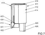
- FIG 7 an alternative embodiment of an assembly aid 411 is shown.
- the guide element 412 has two individual ramps 421, 422, as a result of which they can bend elastically independently of one another. Both ramps 421, 422 each have an inclined locking projection 423, 424. These latching projections 423, 424 engage behind the underside of the first bearing part 7 when the assembly aid 411 is attached to it.
- the assembly aid 411 in this embodiment has an extension 425 which has a stop 426 on its end facing the second bearing part 8. The extension 425 is arranged on the alignment element 412. At the end of the assembly, the stop 426 presses against the bearing 27 of the bearing pin 9, as a result of which a force acts in the direction of the first bearing part 7 on the assembly aid 411.
- the assembly aid 411 also has, like other embodiments, a web 418, which serves as a handle, and a holding device 419.
Landscapes
- Engineering & Computer Science (AREA)
- Mechanical Engineering (AREA)
- Hinges (AREA)
Abstract
Description
- Die Erfindung betrifft eine Montagehilfe für ein zwei Lagerteile aufweisendes Lager eines gegen einen Rahmen schwenkbaren Flügels eines Fensters, einer Fenstertür oder dergleichen, mit einem Ausrichtelement zur lösbaren Verbindung mit einem ersten Lagerteil und einem Führungselement zur Führung eines Lagerbolzens eines zweiten Lagerteils zu dem ersten Lagerteil.
- Eine Montagehilfe ist beispielsweise aus der
EP 1 041 231 A2 bekannt. Diese Montagehilfe ermöglicht bei schweren Türen zwei Scharniere gleichzeitig einzuhängen. Hierzu hat ein an einem feststehenden Scharnierteil lösbar zu befestigender Führungskörper eine Führungsbahn für ein bewegliches Scharnierteil. Diese Montagehilfe eignet sich jedoch nur für fest mit dem Flügel und dem Rahmen verbundene Scharnierteile. - Bei Fenster oder Fenstertüren hat ein im unteren Bereich angeordnetes Ecklager jedoch meist einen schwenkbaren Lagerbolzen, welcher die Bewegung des Flügels in eine Kippstellung ermöglicht. Hierdurch entstehen bei der Montage des Flügels am Rahmen zwei Probleme, nämlich erstens die vorgesehene Ausrichtung des Flügels am Rahmen und zweitens die Ausrichtung der teilweise beweglichen Lagerteile.
- Aus der
WO 2014/026942 A1 ist ein Ecklager für ein Fenster bekannt geworden, bei dem ein Ecklagerbolzen eine Drehhemmung aufweist. Dies führt jedoch zu einem hohen Fertigungsaufwand des Lagers. Zudem hilft diese Drehhemmung nicht beim Ausrichten des Flügels gegenüber dem Rahmen. - Der Erfindung liegt das Problem zugrunde, eine Montagehilfe der eingangs genannten Art so weiter zu bilden, dass sie die Verbindung der Lagerteile insbesondere eines als Ecklager ausgebildeten Lagers während der Montage des Flügels in dem Rahmen ermöglicht.
- Dieses Problem wird erfindungsgemäß dadurch gelöst, dass das Ausrichtelement eine ein Lagerband des ersten Lagerteils teilweise umgreifende Hülse hat und dass das Führungselement an der Hülse angeordnet ist.
- Durch diese Gestaltung lässt sich die Hülse mit dem ersten Lagerteil verbinden, wodurch das Führungselement für das zweite Lagerteil gegenüber dem ersten Lagerteil ausgerichtet ist. Das Führungselement führt bei der Montage des Fensters das zweite Lagerteil in das erste Lagerteil. Anschließend lässt sich die Montagehilfe entfernen und das Lager ist montiert. Das Führungselement kann nahezu beliebig gestaltet sein, um das zweite Lagerteil gegenüber dem ersten Lagerteil auszurichten. Hierdurch werden die Bauteile des Lagers zueinander ausgerichtet, während der Flügel im Rahmen montiert wird.
- Eine lösbare Befestigung der Montagehilfe gestaltet sich gemäß einer anderen vorteilhaften Weiterbildung der Erfindung besonders einfach, wenn das Ausrichtelement eine Halteeinrichtung zur Verrastung oder Verklemmung an dem Lager hat.
- Die Halteeinrichtung gestaltet sich gemäß einer anderen vorteilhaften Weiterbildung der Erfindung konstruktiv besonders einfach, wenn die Halteeinrichtung an der Hülse angeordnete Rastelemente zur Halterung an dem ersten Lagerteil des Lagers hat. Vorzugsweise stehen die Rastelemente von der Hülse radial nach innen ab.
- Zur weiteren Vereinfachung der Halteeinrichtung trägt es gemäß einer anderen vorteilhaften Weiterbildung der Erfindung bei, wenn die Halteeinrichtung an der Hülse angeordnete Klemmstege zur Halterung an dem ersten Lagerteil des Lagers hat.
- Die Führung der Lagerteile bei der Montage des Flügels an dem Rahmen gestaltet sich gemäß einer anderen vorteilhaften Weiterbildung der Erfindung besonders einfach, wenn das Führungselement eine an einer Stirnseite der Hülse angeordnete Rampe hat. Durch diese Gestaltung lässt sich ein bei Ecklagern üblicher schwenkbarer Lagerbolzen des zweiten Lagerteils anheben und in das Lagerband führen.
- Die an der Stirnseite angeordnete Rampe kann jeweils so ausgerichtet werden, dass der Lagerbolzen angehoben und in die C-förmige Hülse eingeführt wird. Ein solches Ausrichten lässt sich jedoch gemäß einer anderen vorteilhaften Weiterbildung der Erfindung einfach vermeiden, wenn eine an der Stirnseite angeordnete Rampe als Einführtrichter ausgebildet ist.
- Zur weiteren Vereinfachung der Handhabung der Montagehilfe trägt es gemäß einer anderen vorteilhaften Weiterbildung der Erfindung bei, wenn die Hülse eine radial nach innen in den Bewegungsbereich des Lagerbolzens des zweiten Lagerteils weisende Auflaufschräge hat. Durch diese Gestaltung wird die Hülse von dem Lagerbolzen weggedrückt, wenn der Lagerbolzen in das Lagerband eingeführt wird. Ein Monteur kann daher an der Hülse sehen, ob das Ecklager wie vorgesehen montiert ist. Bei entsprechender Gestaltung des Lagerbandes ragt die Auflaufschräge vorzugsweise durch eine Öffnung in das Lagerband hinein, so dass die Hülse erst seitlich weggedrückt wird, wenn das Lager montiert ist.
- Die Hülse lässt sich gemäß einer anderen vorteilhaften Weiterbildung der Erfindung einfach greifen, wenn an der Außenseite der Hülse ein Steg als Handhabe absteht.
- Die Montagehilfe lässt sich gemäß einer anderen vorteilhaften Weiterbildung der Erfindung einfach griffbereit am Rahmen oder Flügel bereitstellen, wenn der Steg der Handhabe zur Verrastung in einer Profilnut des Rahmens oder des Flügels vorgesehene Abmessungen hat. Dies trägt zu einem hohen Komfort bei der Nutzung der Montagehilfe bei. Vorzugsweise hat die Handhabe hierfür zwei Stege, welche eine Verklemmung in der Profilnut ermöglichen.
- Die Montagehilfe lässt sich erfindungsgemäß flexibel einsetzen, wenn das Führungselement zwei getrennte Rampen aufweist. Durch diese Gestaltung lassen sich die Rampen leichter radial nach außen biegen, sodass die Hülse auch von oben über das erste Lagerteil geschoben werden kann.
- Die Montagehilfe lässt sich gemäß einer vorteilhaften Weiterbildung der Erfindung nach erfolgter Montage komfortabel vom ersten Lagerteil entfernen, wenn die Rampen an der dem Halteelement zugewandten Seite angeschrägte Rastvorsprünge aufweisen. Durch diese Ausführungsform hintergreift das Führungselement den unteren Teil des ersten Lagerteils zunächst. Wird am Ende der Montage Druck aus Richtung des zweiten Lagerteils auf die Montagehilfe ausgeübt, spreizen sich die Rampen durch die angeschrägten Rastvorsprünge, sodass die Rastung überwunden wird und die Hülse vom ersten Lagerteil abgezogen werden kann.
- Gemäß einer vorteilhaften Weiterbildung der Erfindung läuft das Spreizen der Rampen im Verlauf der Montage automatisch ab, wenn an dem Ausrichteelement ein Fortsatz mit einem Anschlag angeordnet ist, wobei der Anschlag nach erfolgter Montage gegen die Lagerung des Lagerbolzens drückt. Somit erfolgt im Verlauf der Montage des ersten am zweiten Lagerteil durch den Fortsatz ein Kraftübertrag von Seiten des zweiten Lagerteils auf die Montagehilfe. Somit kann diese nach erfolgter Montage einfach von dem ersten Lagerteil abgezogen werden.
- Die Montagehilfe lässt sich gemäß einer anderen vorteilhaften Weiterbildung der Erfindung besonders kostengünstig fertigen, wenn das Ausrichtelement und das Führungselement einstückig gefertigt sind.
- Die Erfindung lässt zahlreiche Ausführungsformen zu. Zur weiteren Verdeutlichung ihres Grundprinzips sind mehrere davon in der Zeichnung dargestellt und werden nachfolgend beschrieben. Diese zeigt in
- Fig.1
- ein Fenster bei der Montage eines Flügels an einem Rahmen mit einer Montagehilfe,
- Fig.2
- eine vergrößerte Darstellung der Montagehilfe aus
Figur 1 mit angrenzenden Bereichen des Rahmens und des Flügels, - Fig.3
- stark vergrößert die Montagehilfe aus
Figur 1 in einer perspektivischen Darstellung, - Fig.4 - 7
- weitere Ausführungsformen der Montagehilfe aus
Figur 1 in perspektivischen Darstellungen. -
Figur 1 zeigt ein Fenster mit einem Rahmen 1, einem Flügel 2 und mit einem unteren, als Ecklager ausgebildeten Lager 3 während der Montage. Im montierten Zustand ist der Flügel 2 zudem von einem oberen Scherenlager 4 an dem Rahmen 1 gehalten und lässt sich um eine vertikale Achse 5 gegenüber dem Rahmen 1 drehen und um eine horizontale Achse 6 kippen. Der Flügel 2 befindet sich in einer geringfügig gekippten Stellung und wird bei der Montage gegenüber dem Rahmen 1 ausgerichtet. -
Figur 2 zeigt vergrößert das als Ecklager ausgebildete Lager 3 während der inFigur 1 beschriebenen Montage. Das als Ecklager ausgebildete Lager 3 hat ein erstes, flügelfestes Lagerteil 7 und ein zweites, rahmenfestes Lagerteil 8. Das rahmenfeste Lagerteil 8 hat einen um die horizontale Achse 6 kippbaren Lagerbolzen 9 mit einer Lagerung 27, welcher bei der Montage des Fensters in ein Lagerband 10 des zweiten, flügelfesten Lagerteils 8 eingeführt wird. Eine Montagehilfe 11 hat ein an dem ersten Lagerteil 7 lösbar befestigtes Ausrichtelement 12 und ein dem freien Ende des Lagerbolzens 9 des zweiten Lagerteils 8 zugewandtes Führungselement 13. Bei dem Einführen des Flügels 2 in den Rahmen 1 führt das Führungselement 13 den Lagerbolzen 9 in das Lagerband 10. Das Lager 3 ist hierdurch montiert. -
Figur 3 zeigt stark vergrößert die Montagehilfe ausFigur 2 in einer perspektivischen Darstellung. Hierbei ist zu erkennen, dass das Ausrichtelement 12 eine im Querschnitt C-förmige Hülse 14 aufweist, welche im montierten Zustand das Lagerband 10 des flügelseitigen Lagerteils 7 teilweise umgreift. Freie Enden der C-förmigen Hülse 14 bilden Klemmstege 20 für eine Halteeinrichtung 19 zur Verklemmung der Montagehilfe 11 an dem flügelseitigen Lagerteil 7. Das Führungselement 13 hat eine an der Stirnseite der Hülse 14 angeordnete Rampe 15. Die Rampe 15 ist als Einführtrichter 16 ausgebildet. Weiterhin hat die Hülse 14 eine radial nach innen in den Bewegungsbereich des Lagerbolzens weisende Auflaufschräge 17. Trifft bei der Montage der Lagerbolzen 9 auf die Auflaufschräge 17, wird die Montagehilfe 11 seitlich von dem flügelseitigen Lagerteil 7 weggedrückt. Die Auflaufschräge 17 kann beispielsweise über eine nicht dargestellte Öffnung in das Lagerband 10 eindringen. An der Außenseite der Hülse 14 stehen zwei Stege 18 ab, von denen in der dargestellten Perspektive einer sichtbar ist. Über die Stege 18 lässt sich die Montagehilfe 11 greifen oder in einer nicht dargestellten Profilnut des Rahmens 1 oder des Flügels 2 einklemmen. Die Montagehilfe 11 ist einstückig aus Kunststoff oder Metall insbesondere im Spritzgussverfahren gefertigt. -
Figur 4 zeigt eine weitere Ausführungsform einer Montagehilfe 111 bei der ein Ausrichtelement 112 eine Hülse 114 mit zwei Klemmstegen 120 einer Halteeinrichtung 119 hat. Die Klemmstege 120 sind federelastisch gestaltet und ermöglichen eine Klemmverbindung an dem ersten Lagerteil 7 des Lagers 3. Ein am freien Ende der Hülse 114 ist ein Führungselement 113 mit einer als Einführtrichter 116 ausgebildeten Rampe 115 angeordnet. Ansonsten ist die Montagehilfe 111 wie die ausFigur 3 aufgebaut. -
Figur 5 zeigt eine weitere Ausführungsform einer Montagehilfe 211 mit einer Rastelemente 221 aufweisende Halteeinrichtung 219 zur Halterung eines eine Hülse 214 aufweisenden Ausrichtelements 212 an dem ersten Lagerteil 7. Ein Führungselement 213 hat eine hervorstehende Rampe 215 zur Führung des Lagerbolzens 9 des zweiten Lagerteils 8. -
Figur 6 zeigt eine weitere Ausführungsform einer Montagehilfe 311, bei der eine Hülse 314 eines Ausrichtelements 312 eine Halteeinrichtung 319 mit Klemmstegen 320 zum Verklemmen mit dem ersten Lagerteil 7 hat. Ein Führungselement 313 mit einer Rampe 315 steht von einer Stirnseite der Hülse 314 ab. - In
Figur 7 wird eine alternative Ausführungsform einer Montagehilfe 411 gezeigt. Bei dieser weist das Führungselement 412 zwei einzelnen Rampen 421, 422 auf, wodurch diese sich unabhängig voneinander elastisch verbiegen können. Beide Rampen 421, 422 weisen jeweils einen angeschrägten Rastvorsprung 423, 424 auf. Diese Rastvorsprünge 423, 424 hintergreifen die Unterseite des ersten Lagerteils 7, wenn die Montagehilfe 411 an diesem angebracht ist. Darüber hinaus weist die Montagehilfe 411 in dieser Ausführungsform einen Fortsatz 425 auf, welcher an seinem dem zweiten Lagerteil 8 zugewandten Ende einen Anschlag 426 hat. Der Fortsatz 425 ist an dem Ausrichteelement 412 angeordnet. Der Anschlag 426 drückt am Ende der Montage gegen die Lagerung 27 des Lagerbolzens 9, wodurch eine Kraft in Richtung des ersten Lagerteils 7 auf die Montagehilfe 411 wirkt. Durch diese Kraft und die angeschrägten Rastvorsprünge 423, 424 wird die Rastung dieser Rastvorsprünge 423, 424 aufgehoben und die Montagehilfe 411 kann von dem ersten Lagerteil 7 abgezogen werden. Die Montagehilfe 411 weist darüber hinaus, wie bereits andere Ausführungsformen, einen Steg 418, welcher als Handhabe dient und eine Halteeinrichtung 419 auf.
Claims (13)
- Montagehilfe (11, 111, 211, 311, 411) für ein zwei Lagerteile (7, 8) aufweisendes Lager (3) eines gegen einen Rahmen (1) schwenkbaren Flügels (2) eines Fensters, einer Fenstertür oder dergleichen, mit einem Ausrichtelement (12, 112, 212, 312, 412) zur lösbaren Verbindung mit einem ersten Lagerteil und einem Führungselement (13, 113, 213, 313, 413) zur Führung eines Lagerbolzens (9) eines zweiten Lagerteils (8) zu dem ersten Lagerteil (7), dadurch gekennzeichnet, dass das Ausrichtelement (12, 112, 212, 312, 412) eine ein Lagerband (10) des ersten Lagerteils (7) teilweise umgreifende Hülse (14, 114, 214, 314, 414) hat und dass das Führungselement (13, 113, 213, 313, 413) an der Hülse (14, 114, 214, 314, 414) angeordnet ist.
- Montagehilfe nach Anspruch 1, dadurch gekennzeichnet, dass das Ausrichtelement (12, 112, 212, 312, 412) eine Halteeinrichtung (19, 119, 219, 319, 419) zur Verrastung oder Verklemmung an dem Lager hat.
- Montagehilfe nach Anspruch 1 oder 2, dadurch gekennzeichnet, dass die Halteeinrichtung (219) an der Hülse (214) angeordnete Rastelemente (221) zur Halterung an dem ersten Lagerteil (7) des Lagers (3) hat.
- Montagehilfe nach zumindest einem der vorhergehenden Ansprüche, dadurch gekennzeichnet, dass die Halteeinrichtung (19, 119, 319) an der Hülse (14, 114, 314) angeordnete Klemmstege (20, 120, 320) zur Halterung an dem ersten Lagerteil (7) des Lagers (3) hat.
- Montagehilfe nach zumindest einem der vorhergehenden Ansprüche, dadurch gekennzeichnet, dass das Führungselement (13, 113, 213, 313) eine an einer Stirnseite der Hülse (14, 114, 214, 314) angeordnete Rampe (15, 115, 215, 315) hat.
- Montagehilfe nach Anspruch 5, dadurch gekennzeichnet, dass eine an der Stirnseite angeordnete Rampe (15, 115) als Einführtrichter (16, 116) ausgebildet ist.
- Montagehilfe nach zumindest einem der vorhergehenden Ansprüche, dadurch gekennzeichnet, dass die Hülse (14, 114, 214) eine radial nach innen in den Bewegungsbereich des Lagerbolzens (9) des zweiten Lagerteils (8) weisende Auflaufschräge (17) hat.
- Montagehilfe nach zumindest einem der vorhergehenden Ansprüche, dadurch gekennzeichnet, dass an der Außenseite der Hülse (14) ein Steg (18, 418) als Handhabe absteht.
- Montagehilfe nach Anspruch 8, dadurch gekennzeichnet, dass der Steg (18) der Handhabe zur Verrastung in einer Profilnut des Rahmens (1) oder des Flügels (2) vorgesehene Abmessungen hat.
- Montagehilfe nach zumindest einem der vorhergehenden Ansprüche, dadurch gekennzeichnet, dass das Führungselement (413) zwei getrennte Rampen (421, 422) aufweist.
- Montagehilfe nach Anspruch 10, dadurch gekennzeichnet, dass die Rampen (421, 422) an der dem Halteelement (414) zugewandten Seite angeschrägte Rastvorsprünge (423, 424) aufweisen.
- Montagehilfe nach einem der Ansprüche 10 oder 11, dadurch gekennzeichnet, dass an dem Ausrichteelement (412) ein Fortsatz (425) mit einem Anschlag (426) angeordnet ist, wobei der Anschlag (426) nach erfolgter Montage gegen die Lagerung (27) des Lagerbolzens (9) drückt.
- Montagehilfe nach zumindest einem der vorhergehenden Ansprüche, dadurch gekennzeichnet, dass das Ausrichtelement (12, 112, 212, 312, 412) und das Führungselement (13, 113, 213, 313, 413) einstückig gefertigt sind.
Applications Claiming Priority (1)
| Application Number | Priority Date | Filing Date | Title |
|---|---|---|---|
| DE102020200666.0A DE102020200666A1 (de) | 2020-01-21 | 2020-01-21 | Montagehilfe für ein zwei Lagerteile aufweisendes Lager |
Publications (2)
| Publication Number | Publication Date |
|---|---|
| EP3854969A1 true EP3854969A1 (de) | 2021-07-28 |
| EP3854969B1 EP3854969B1 (de) | 2026-03-11 |
Family
ID=74181013
Family Applications (1)
| Application Number | Title | Priority Date | Filing Date |
|---|---|---|---|
| EP21151365.0A Active EP3854969B1 (de) | 2020-01-21 | 2021-01-13 | Montagehilfe für ein zwei lagerteile aufweisendes lager |
Country Status (2)
| Country | Link |
|---|---|
| EP (1) | EP3854969B1 (de) |
| DE (1) | DE102020200666A1 (de) |
Citations (5)
| Publication number | Priority date | Publication date | Assignee | Title |
|---|---|---|---|---|
| FR2702174A1 (fr) * | 1992-10-21 | 1994-09-09 | Thiriot Raymond | Dispositif destiné au guidage de gond lors de la remise en place de portes ou fenêtres. |
| DE29706761U1 (de) * | 1997-04-15 | 1997-08-21 | Tavernier, Albert, 67125 Dannstadt-Schauernheim | Türbandeinführungshilfe, um eine Tür in die Bänder an der Zarge leichter einführen zu können |
| EP1041231A2 (de) | 1999-03-30 | 2000-10-04 | Adolf Würth GmbH & Co. KG | Vorrichtung zum Führen eines bewegbaren Scharnierteils zu einem stationären Scharnierteil |
| WO2006134615A1 (en) * | 2005-06-13 | 2006-12-21 | Rosada Window System Spa | A kit for the assembly and removal of the mobile wings of door and window frames |
| WO2014026942A1 (de) | 2012-08-16 | 2014-02-20 | Roto Frank Ag | Einstellbares ecklager für einen flügel eines fensters, einer tür oder dergleichen |
-
2020
- 2020-01-21 DE DE102020200666.0A patent/DE102020200666A1/de not_active Withdrawn
-
2021
- 2021-01-13 EP EP21151365.0A patent/EP3854969B1/de active Active
Patent Citations (5)
| Publication number | Priority date | Publication date | Assignee | Title |
|---|---|---|---|---|
| FR2702174A1 (fr) * | 1992-10-21 | 1994-09-09 | Thiriot Raymond | Dispositif destiné au guidage de gond lors de la remise en place de portes ou fenêtres. |
| DE29706761U1 (de) * | 1997-04-15 | 1997-08-21 | Tavernier, Albert, 67125 Dannstadt-Schauernheim | Türbandeinführungshilfe, um eine Tür in die Bänder an der Zarge leichter einführen zu können |
| EP1041231A2 (de) | 1999-03-30 | 2000-10-04 | Adolf Würth GmbH & Co. KG | Vorrichtung zum Führen eines bewegbaren Scharnierteils zu einem stationären Scharnierteil |
| WO2006134615A1 (en) * | 2005-06-13 | 2006-12-21 | Rosada Window System Spa | A kit for the assembly and removal of the mobile wings of door and window frames |
| WO2014026942A1 (de) | 2012-08-16 | 2014-02-20 | Roto Frank Ag | Einstellbares ecklager für einen flügel eines fensters, einer tür oder dergleichen |
Also Published As
| Publication number | Publication date |
|---|---|
| EP3854969B1 (de) | 2026-03-11 |
| DE102020200666A1 (de) | 2021-07-22 |
Similar Documents
| Publication | Publication Date | Title |
|---|---|---|
| EP3612698B1 (de) | Scharnier für ein schaltschrankgehäuse sowie ein entsprechendes schaltschrankgehäuse und montageverfahren | |
| EP3928392B1 (de) | Scharnieranordnung für einen schaltschrank und ein entsprechendes verfahren | |
| WO2017001226A1 (de) | Absenkdichtung | |
| DE2639446C2 (de) | ||
| EP3854969B1 (de) | Montagehilfe für ein zwei lagerteile aufweisendes lager | |
| DE102012101338B4 (de) | Wischerblatt-Montagewinkel | |
| DE202016106504U1 (de) | Montagewerkzeug für die Montage einer Schaltschranktür an einem Schaltschrankgehäuse und eine entsprechende Schaltschrankanordnung | |
| DE102008041083A1 (de) | Beschlagteil eines Treibstangenbeschlages | |
| AT524332B1 (de) | Anordnung zur Führung eines bewegbaren Möbelteils | |
| EP4074931A1 (de) | Beschlag mit einem durch längsschieben arretierbaren rasthaken | |
| DE20109265U1 (de) | Verriegelungsvorrichtung | |
| DE102018100550A1 (de) | Führungsgleiter für ein schiebetür- und/oder schiebefenstersystem, beweglicher schieberahmen mit einem führungsgleiter sowie schiebetür- und/oder schiebefenstersystem mit führungsleiter | |
| EP2317047A2 (de) | Beschlaganordnung | |
| EP2099989A2 (de) | Treibstangengetriebe | |
| EP3088639B1 (de) | Vorrichtung zum ausrichten von einander gegenüberstehend anzuordnenden beschlagteilen | |
| EP3235984B1 (de) | Beschlag für ein fenster, verfahren zum herstellen des beschlags sowie entsprechendes fenster | |
| DE20311828U1 (de) | Schließeinrichtung | |
| EP2132391B1 (de) | Treibstangenanordnung mit mindestens einer treibstange und mindestens einem treibstangenführungselement | |
| EP3865649A1 (de) | Vorrichtung zur begrenzung einer öffnungsweite eines gegenüber einem rahmen um zumindest eine achse schwenkbaren flügels | |
| EP3449075B1 (de) | Kraftfahrzeugtürgriffanordnung mit führung des griffhakens | |
| DE29600891U1 (de) | Sicherungseinrichtung | |
| DE10015095A1 (de) | Verriegelungsvorrichtung für einen Türflügel | |
| EP1992772B1 (de) | Beschlaganordnung | |
| EP4166741A1 (de) | Beschlag | |
| EP1734212B1 (de) | Beschlaganordnung |
Legal Events
| Date | Code | Title | Description |
|---|---|---|---|
| PUAI | Public reference made under article 153(3) epc to a published international application that has entered the european phase |
Free format text: ORIGINAL CODE: 0009012 |
|
| STAA | Information on the status of an ep patent application or granted ep patent |
Free format text: STATUS: THE APPLICATION HAS BEEN PUBLISHED |
|
| AK | Designated contracting states |
Kind code of ref document: A1 Designated state(s): AL AT BE BG CH CY CZ DE DK EE ES FI FR GB GR HR HU IE IS IT LI LT LU LV MC MK MT NL NO PL PT RO RS SE SI SK SM TR |
|
| STAA | Information on the status of an ep patent application or granted ep patent |
Free format text: STATUS: REQUEST FOR EXAMINATION WAS MADE |
|
| 17P | Request for examination filed |
Effective date: 20211213 |
|
| RBV | Designated contracting states (corrected) |
Designated state(s): AL AT BE BG CH CY CZ DE DK EE ES FI FR GB GR HR HU IE IS IT LI LT LU LV MC MK MT NL NO PL PT RO RS SE SI SK SM TR |
|
| P01 | Opt-out of the competence of the unified patent court (upc) registered |
Effective date: 20230516 |
|
| STAA | Information on the status of an ep patent application or granted ep patent |
Free format text: STATUS: EXAMINATION IS IN PROGRESS |
|
| 17Q | First examination report despatched |
Effective date: 20231109 |
|
| RAP3 | Party data changed (applicant data changed or rights of an application transferred) |
Owner name: AUG. WINKHAUS SE & CO. KG |
|
| RAP1 | Party data changed (applicant data changed or rights of an application transferred) |
Owner name: AUG. WINKHAUS SE |
|
| GRAP | Despatch of communication of intention to grant a patent |
Free format text: ORIGINAL CODE: EPIDOSNIGR1 |
|
| STAA | Information on the status of an ep patent application or granted ep patent |
Free format text: STATUS: GRANT OF PATENT IS INTENDED |
|
| INTG | Intention to grant announced |
Effective date: 20251029 |
|
| GRAS | Grant fee paid |
Free format text: ORIGINAL CODE: EPIDOSNIGR3 |
|
| GRAA | (expected) grant |
Free format text: ORIGINAL CODE: 0009210 |
|
| STAA | Information on the status of an ep patent application or granted ep patent |
Free format text: STATUS: THE PATENT HAS BEEN GRANTED |
|
| AK | Designated contracting states |
Kind code of ref document: B1 Designated state(s): AL AT BE BG CH CY CZ DE DK EE ES FI FR GB GR HR HU IE IS IT LI LT LU LV MC MK MT NL NO PL PT RO RS SE SI SK SM TR |
|
| REG | Reference to a national code |
Ref country code: CH Ref legal event code: F10 Free format text: ST27 STATUS EVENT CODE: U-0-0-F10-F00 (AS PROVIDED BY THE NATIONAL OFFICE) Effective date: 20260311 Ref country code: GB Ref legal event code: FG4D Free format text: NOT ENGLISH |
|
| REG | Reference to a national code |
Ref country code: DE Ref legal event code: R096 Ref document number: 502021009999 Country of ref document: DE |
|
| REG | Reference to a national code |
Ref country code: IE Ref legal event code: FG4D Free format text: LANGUAGE OF EP DOCUMENT: GERMAN |