EP3854448B1 - Ventrikelunterstützungsvorrichtung - Google Patents
Ventrikelunterstützungsvorrichtung Download PDFInfo
- Publication number
- EP3854448B1 EP3854448B1 EP21162363.2A EP21162363A EP3854448B1 EP 3854448 B1 EP3854448 B1 EP 3854448B1 EP 21162363 A EP21162363 A EP 21162363A EP 3854448 B1 EP3854448 B1 EP 3854448B1
- Authority
- EP
- European Patent Office
- Prior art keywords
- vad
- control device
- heart
- speed
- aop
- Prior art date
- Legal status (The legal status is an assumption and is not a legal conclusion. Google has not performed a legal analysis and makes no representation as to the accuracy of the status listed.)
- Active
Links
- 230000002861 ventricular Effects 0.000 title claims description 27
- 230000000747 cardiac effect Effects 0.000 claims description 87
- 239000008280 blood Substances 0.000 claims description 74
- 210000004369 blood Anatomy 0.000 claims description 74
- 230000036772 blood pressure Effects 0.000 claims description 42
- 230000017531 blood circulation Effects 0.000 claims description 34
- 230000004075 alteration Effects 0.000 claims description 27
- 210000000709 aorta Anatomy 0.000 claims description 15
- 108010047303 von Willebrand Factor Proteins 0.000 claims description 15
- 102100036537 von Willebrand factor Human genes 0.000 claims description 15
- 229960001134 von willebrand factor Drugs 0.000 claims description 15
- 230000004872 arterial blood pressure Effects 0.000 claims description 14
- 230000000541 pulsatile effect Effects 0.000 claims description 14
- 230000008602 contraction Effects 0.000 claims description 13
- 210000001147 pulmonary artery Anatomy 0.000 claims description 12
- 210000001367 artery Anatomy 0.000 claims description 11
- 210000001765 aortic valve Anatomy 0.000 claims description 10
- 238000011217 control strategy Methods 0.000 claims description 7
- 230000003205 diastolic effect Effects 0.000 claims description 7
- 230000001419 dependent effect Effects 0.000 claims description 6
- 230000007115 recruitment Effects 0.000 claims description 6
- 239000000463 material Substances 0.000 claims description 5
- 230000008878 coupling Effects 0.000 claims description 4
- 238000010168 coupling process Methods 0.000 claims description 4
- 238000005859 coupling reaction Methods 0.000 claims description 4
- 238000012545 processing Methods 0.000 description 29
- 238000005086 pumping Methods 0.000 description 18
- 230000000694 effects Effects 0.000 description 14
- 230000008859 change Effects 0.000 description 10
- 230000006870 function Effects 0.000 description 7
- 238000005259 measurement Methods 0.000 description 7
- 230000001360 synchronised effect Effects 0.000 description 7
- 210000005240 left ventricle Anatomy 0.000 description 6
- 238000012423 maintenance Methods 0.000 description 6
- 230000010412 perfusion Effects 0.000 description 6
- 230000001960 triggered effect Effects 0.000 description 6
- 238000004458 analytical method Methods 0.000 description 5
- 230000001746 atrial effect Effects 0.000 description 5
- 238000004590 computer program Methods 0.000 description 5
- 238000004088 simulation Methods 0.000 description 5
- 230000007812 deficiency Effects 0.000 description 4
- 238000010586 diagram Methods 0.000 description 4
- 230000036581 peripheral resistance Effects 0.000 description 4
- 230000000740 bleeding effect Effects 0.000 description 3
- 238000004364 calculation method Methods 0.000 description 3
- 230000004217 heart function Effects 0.000 description 3
- 210000004115 mitral valve Anatomy 0.000 description 3
- 230000036316 preload Effects 0.000 description 3
- 230000009467 reduction Effects 0.000 description 3
- 230000002792 vascular Effects 0.000 description 3
- 206010018910 Haemolysis Diseases 0.000 description 2
- 238000004891 communication Methods 0.000 description 2
- 230000006378 damage Effects 0.000 description 2
- 230000003247 decreasing effect Effects 0.000 description 2
- 238000011161 development Methods 0.000 description 2
- 230000010247 heart contraction Effects 0.000 description 2
- 230000000004 hemodynamic effect Effects 0.000 description 2
- 230000008588 hemolysis Effects 0.000 description 2
- 238000012544 monitoring process Methods 0.000 description 2
- 230000003287 optical effect Effects 0.000 description 2
- 210000005241 right ventricle Anatomy 0.000 description 2
- 229920002994 synthetic fiber Polymers 0.000 description 2
- 230000009885 systemic effect Effects 0.000 description 2
- 102000003886 Glycoproteins Human genes 0.000 description 1
- 108090000288 Glycoproteins Proteins 0.000 description 1
- 208000010496 Heart Arrest Diseases 0.000 description 1
- 230000036586 afterload Effects 0.000 description 1
- 230000003190 augmentative effect Effects 0.000 description 1
- 230000009286 beneficial effect Effects 0.000 description 1
- 210000004204 blood vessel Anatomy 0.000 description 1
- 238000004422 calculation algorithm Methods 0.000 description 1
- 239000003990 capacitor Substances 0.000 description 1
- 230000009194 climbing Effects 0.000 description 1
- 230000006735 deficit Effects 0.000 description 1
- 230000003111 delayed effect Effects 0.000 description 1
- 238000005516 engineering process Methods 0.000 description 1
- 239000012530 fluid Substances 0.000 description 1
- 230000004927 fusion Effects 0.000 description 1
- 230000007274 generation of a signal involved in cell-cell signaling Effects 0.000 description 1
- 230000023597 hemostasis Effects 0.000 description 1
- 238000002513 implantation Methods 0.000 description 1
- 238000012067 mathematical method Methods 0.000 description 1
- 238000013178 mathematical model Methods 0.000 description 1
- 230000004048 modification Effects 0.000 description 1
- 238000012986 modification Methods 0.000 description 1
- 239000013307 optical fiber Substances 0.000 description 1
- 230000002093 peripheral effect Effects 0.000 description 1
- 230000010363 phase shift Effects 0.000 description 1
- 230000004962 physiological condition Effects 0.000 description 1
- 230000003334 potential effect Effects 0.000 description 1
- 238000010926 purge Methods 0.000 description 1
- 238000010223 real-time analysis Methods 0.000 description 1
- 238000011084 recovery Methods 0.000 description 1
- 230000004044 response Effects 0.000 description 1
- 230000002441 reversible effect Effects 0.000 description 1
- 230000035939 shock Effects 0.000 description 1
- 230000003319 supportive effect Effects 0.000 description 1
- 238000002560 therapeutic procedure Methods 0.000 description 1
- 230000036962 time dependent Effects 0.000 description 1
- 210000005166 vasculature Anatomy 0.000 description 1
- 230000009184 walking Effects 0.000 description 1
Images


Classifications
-
- G—PHYSICS
- G16—INFORMATION AND COMMUNICATION TECHNOLOGY [ICT] SPECIALLY ADAPTED FOR SPECIFIC APPLICATION FIELDS
- G16H—HEALTHCARE INFORMATICS, i.e. INFORMATION AND COMMUNICATION TECHNOLOGY [ICT] SPECIALLY ADAPTED FOR THE HANDLING OR PROCESSING OF MEDICAL OR HEALTHCARE DATA
- G16H40/00—ICT specially adapted for the management or administration of healthcare resources or facilities; ICT specially adapted for the management or operation of medical equipment or devices
- G16H40/60—ICT specially adapted for the management or administration of healthcare resources or facilities; ICT specially adapted for the management or operation of medical equipment or devices for the operation of medical equipment or devices
- G16H40/63—ICT specially adapted for the management or administration of healthcare resources or facilities; ICT specially adapted for the management or operation of medical equipment or devices for the operation of medical equipment or devices for local operation
-
- A—HUMAN NECESSITIES
- A61—MEDICAL OR VETERINARY SCIENCE; HYGIENE
- A61M—DEVICES FOR INTRODUCING MEDIA INTO, OR ONTO, THE BODY; DEVICES FOR TRANSDUCING BODY MEDIA OR FOR TAKING MEDIA FROM THE BODY; DEVICES FOR PRODUCING OR ENDING SLEEP OR STUPOR
- A61M60/00—Blood pumps; Devices for mechanical circulatory actuation; Balloon pumps for circulatory assistance
- A61M60/10—Location thereof with respect to the patient's body
- A61M60/122—Implantable pumps or pumping devices, i.e. the blood being pumped inside the patient's body
- A61M60/126—Implantable pumps or pumping devices, i.e. the blood being pumped inside the patient's body implantable via, into, inside, in line, branching on, or around a blood vessel
- A61M60/13—Implantable pumps or pumping devices, i.e. the blood being pumped inside the patient's body implantable via, into, inside, in line, branching on, or around a blood vessel by means of a catheter allowing explantation, e.g. catheter pumps temporarily introduced via the vascular system
-
- A—HUMAN NECESSITIES
- A61—MEDICAL OR VETERINARY SCIENCE; HYGIENE
- A61M—DEVICES FOR INTRODUCING MEDIA INTO, OR ONTO, THE BODY; DEVICES FOR TRANSDUCING BODY MEDIA OR FOR TAKING MEDIA FROM THE BODY; DEVICES FOR PRODUCING OR ENDING SLEEP OR STUPOR
- A61M60/00—Blood pumps; Devices for mechanical circulatory actuation; Balloon pumps for circulatory assistance
- A61M60/10—Location thereof with respect to the patient's body
- A61M60/122—Implantable pumps or pumping devices, i.e. the blood being pumped inside the patient's body
- A61M60/165—Implantable pumps or pumping devices, i.e. the blood being pumped inside the patient's body implantable in, on, or around the heart
- A61M60/178—Implantable pumps or pumping devices, i.e. the blood being pumped inside the patient's body implantable in, on, or around the heart drawing blood from a ventricle and returning the blood to the arterial system via a cannula external to the ventricle, e.g. left or right ventricular assist devices
-
- A—HUMAN NECESSITIES
- A61—MEDICAL OR VETERINARY SCIENCE; HYGIENE
- A61M—DEVICES FOR INTRODUCING MEDIA INTO, OR ONTO, THE BODY; DEVICES FOR TRANSDUCING BODY MEDIA OR FOR TAKING MEDIA FROM THE BODY; DEVICES FOR PRODUCING OR ENDING SLEEP OR STUPOR
- A61M60/00—Blood pumps; Devices for mechanical circulatory actuation; Balloon pumps for circulatory assistance
- A61M60/10—Location thereof with respect to the patient's body
- A61M60/122—Implantable pumps or pumping devices, i.e. the blood being pumped inside the patient's body
- A61M60/126—Implantable pumps or pumping devices, i.e. the blood being pumped inside the patient's body implantable via, into, inside, in line, branching on, or around a blood vessel
- A61M60/135—Implantable pumps or pumping devices, i.e. the blood being pumped inside the patient's body implantable via, into, inside, in line, branching on, or around a blood vessel inside a blood vessel, e.g. using grafting
-
- A—HUMAN NECESSITIES
- A61—MEDICAL OR VETERINARY SCIENCE; HYGIENE
- A61M—DEVICES FOR INTRODUCING MEDIA INTO, OR ONTO, THE BODY; DEVICES FOR TRANSDUCING BODY MEDIA OR FOR TAKING MEDIA FROM THE BODY; DEVICES FOR PRODUCING OR ENDING SLEEP OR STUPOR
- A61M60/00—Blood pumps; Devices for mechanical circulatory actuation; Balloon pumps for circulatory assistance
- A61M60/10—Location thereof with respect to the patient's body
- A61M60/122—Implantable pumps or pumping devices, i.e. the blood being pumped inside the patient's body
- A61M60/126—Implantable pumps or pumping devices, i.e. the blood being pumped inside the patient's body implantable via, into, inside, in line, branching on, or around a blood vessel
- A61M60/148—Implantable pumps or pumping devices, i.e. the blood being pumped inside the patient's body implantable via, into, inside, in line, branching on, or around a blood vessel in line with a blood vessel using resection or like techniques, e.g. permanent endovascular heart assist devices
-
- A—HUMAN NECESSITIES
- A61—MEDICAL OR VETERINARY SCIENCE; HYGIENE
- A61M—DEVICES FOR INTRODUCING MEDIA INTO, OR ONTO, THE BODY; DEVICES FOR TRANSDUCING BODY MEDIA OR FOR TAKING MEDIA FROM THE BODY; DEVICES FOR PRODUCING OR ENDING SLEEP OR STUPOR
- A61M60/00—Blood pumps; Devices for mechanical circulatory actuation; Balloon pumps for circulatory assistance
- A61M60/20—Type thereof
- A61M60/205—Non-positive displacement blood pumps
- A61M60/216—Non-positive displacement blood pumps including a rotating member acting on the blood, e.g. impeller
- A61M60/237—Non-positive displacement blood pumps including a rotating member acting on the blood, e.g. impeller the blood flow through the rotating member having mainly axial components, e.g. axial flow pumps
-
- A—HUMAN NECESSITIES
- A61—MEDICAL OR VETERINARY SCIENCE; HYGIENE
- A61M—DEVICES FOR INTRODUCING MEDIA INTO, OR ONTO, THE BODY; DEVICES FOR TRANSDUCING BODY MEDIA OR FOR TAKING MEDIA FROM THE BODY; DEVICES FOR PRODUCING OR ENDING SLEEP OR STUPOR
- A61M60/00—Blood pumps; Devices for mechanical circulatory actuation; Balloon pumps for circulatory assistance
- A61M60/40—Details relating to driving
- A61M60/403—Details relating to driving for non-positive displacement blood pumps
- A61M60/408—Details relating to driving for non-positive displacement blood pumps the force acting on the blood contacting member being mechanical, e.g. transmitted by a shaft or cable
- A61M60/411—Details relating to driving for non-positive displacement blood pumps the force acting on the blood contacting member being mechanical, e.g. transmitted by a shaft or cable generated by an electromotor
- A61M60/414—Details relating to driving for non-positive displacement blood pumps the force acting on the blood contacting member being mechanical, e.g. transmitted by a shaft or cable generated by an electromotor transmitted by a rotating cable, e.g. for blood pumps mounted on a catheter
-
- A—HUMAN NECESSITIES
- A61—MEDICAL OR VETERINARY SCIENCE; HYGIENE
- A61M—DEVICES FOR INTRODUCING MEDIA INTO, OR ONTO, THE BODY; DEVICES FOR TRANSDUCING BODY MEDIA OR FOR TAKING MEDIA FROM THE BODY; DEVICES FOR PRODUCING OR ENDING SLEEP OR STUPOR
- A61M60/00—Blood pumps; Devices for mechanical circulatory actuation; Balloon pumps for circulatory assistance
- A61M60/40—Details relating to driving
- A61M60/403—Details relating to driving for non-positive displacement blood pumps
- A61M60/422—Details relating to driving for non-positive displacement blood pumps the force acting on the blood contacting member being electromagnetic, e.g. using canned motor pumps
-
- A—HUMAN NECESSITIES
- A61—MEDICAL OR VETERINARY SCIENCE; HYGIENE
- A61M—DEVICES FOR INTRODUCING MEDIA INTO, OR ONTO, THE BODY; DEVICES FOR TRANSDUCING BODY MEDIA OR FOR TAKING MEDIA FROM THE BODY; DEVICES FOR PRODUCING OR ENDING SLEEP OR STUPOR
- A61M60/00—Blood pumps; Devices for mechanical circulatory actuation; Balloon pumps for circulatory assistance
- A61M60/50—Details relating to control
- A61M60/508—Electronic control means, e.g. for feedback regulation
- A61M60/515—Regulation using real-time patient data
- A61M60/523—Regulation using real-time patient data using blood flow data, e.g. from blood flow transducers
-
- A—HUMAN NECESSITIES
- A61—MEDICAL OR VETERINARY SCIENCE; HYGIENE
- A61M—DEVICES FOR INTRODUCING MEDIA INTO, OR ONTO, THE BODY; DEVICES FOR TRANSDUCING BODY MEDIA OR FOR TAKING MEDIA FROM THE BODY; DEVICES FOR PRODUCING OR ENDING SLEEP OR STUPOR
- A61M60/00—Blood pumps; Devices for mechanical circulatory actuation; Balloon pumps for circulatory assistance
- A61M60/50—Details relating to control
- A61M60/508—Electronic control means, e.g. for feedback regulation
- A61M60/515—Regulation using real-time patient data
- A61M60/531—Regulation using real-time patient data using blood pressure data, e.g. from blood pressure sensors
-
- A—HUMAN NECESSITIES
- A61—MEDICAL OR VETERINARY SCIENCE; HYGIENE
- A61M—DEVICES FOR INTRODUCING MEDIA INTO, OR ONTO, THE BODY; DEVICES FOR TRANSDUCING BODY MEDIA OR FOR TAKING MEDIA FROM THE BODY; DEVICES FOR PRODUCING OR ENDING SLEEP OR STUPOR
- A61M60/00—Blood pumps; Devices for mechanical circulatory actuation; Balloon pumps for circulatory assistance
- A61M60/50—Details relating to control
- A61M60/508—Electronic control means, e.g. for feedback regulation
- A61M60/538—Regulation using real-time blood pump operational parameter data, e.g. motor current
- A61M60/546—Regulation using real-time blood pump operational parameter data, e.g. motor current of blood flow, e.g. by adapting rotor speed
-
- A—HUMAN NECESSITIES
- A61—MEDICAL OR VETERINARY SCIENCE; HYGIENE
- A61M—DEVICES FOR INTRODUCING MEDIA INTO, OR ONTO, THE BODY; DEVICES FOR TRANSDUCING BODY MEDIA OR FOR TAKING MEDIA FROM THE BODY; DEVICES FOR PRODUCING OR ENDING SLEEP OR STUPOR
- A61M60/00—Blood pumps; Devices for mechanical circulatory actuation; Balloon pumps for circulatory assistance
- A61M60/50—Details relating to control
- A61M60/508—Electronic control means, e.g. for feedback regulation
- A61M60/538—Regulation using real-time blood pump operational parameter data, e.g. motor current
- A61M60/554—Regulation using real-time blood pump operational parameter data, e.g. motor current of blood pressure
-
- A—HUMAN NECESSITIES
- A61—MEDICAL OR VETERINARY SCIENCE; HYGIENE
- A61M—DEVICES FOR INTRODUCING MEDIA INTO, OR ONTO, THE BODY; DEVICES FOR TRANSDUCING BODY MEDIA OR FOR TAKING MEDIA FROM THE BODY; DEVICES FOR PRODUCING OR ENDING SLEEP OR STUPOR
- A61M60/00—Blood pumps; Devices for mechanical circulatory actuation; Balloon pumps for circulatory assistance
- A61M60/50—Details relating to control
- A61M60/508—Electronic control means, e.g. for feedback regulation
- A61M60/562—Electronic control means, e.g. for feedback regulation for making blood flow pulsatile in blood pumps that do not intrinsically create pulsatile flow
- A61M60/569—Electronic control means, e.g. for feedback regulation for making blood flow pulsatile in blood pumps that do not intrinsically create pulsatile flow synchronous with the native heart beat
-
- A—HUMAN NECESSITIES
- A61—MEDICAL OR VETERINARY SCIENCE; HYGIENE
- A61M—DEVICES FOR INTRODUCING MEDIA INTO, OR ONTO, THE BODY; DEVICES FOR TRANSDUCING BODY MEDIA OR FOR TAKING MEDIA FROM THE BODY; DEVICES FOR PRODUCING OR ENDING SLEEP OR STUPOR
- A61M60/00—Blood pumps; Devices for mechanical circulatory actuation; Balloon pumps for circulatory assistance
- A61M60/80—Constructional details other than related to driving
- A61M60/802—Constructional details other than related to driving of non-positive displacement blood pumps
- A61M60/81—Pump housings
- A61M60/816—Sensors arranged on or in the housing, e.g. ultrasound flow sensors
-
- A—HUMAN NECESSITIES
- A61—MEDICAL OR VETERINARY SCIENCE; HYGIENE
- A61M—DEVICES FOR INTRODUCING MEDIA INTO, OR ONTO, THE BODY; DEVICES FOR TRANSDUCING BODY MEDIA OR FOR TAKING MEDIA FROM THE BODY; DEVICES FOR PRODUCING OR ENDING SLEEP OR STUPOR
- A61M60/00—Blood pumps; Devices for mechanical circulatory actuation; Balloon pumps for circulatory assistance
- A61M60/80—Constructional details other than related to driving
- A61M60/855—Constructional details other than related to driving of implantable pumps or pumping devices
- A61M60/857—Implantable blood tubes
-
- G—PHYSICS
- G16—INFORMATION AND COMMUNICATION TECHNOLOGY [ICT] SPECIALLY ADAPTED FOR SPECIFIC APPLICATION FIELDS
- G16H—HEALTHCARE INFORMATICS, i.e. INFORMATION AND COMMUNICATION TECHNOLOGY [ICT] SPECIALLY ADAPTED FOR THE HANDLING OR PROCESSING OF MEDICAL OR HEALTHCARE DATA
- G16H50/00—ICT specially adapted for medical diagnosis, medical simulation or medical data mining; ICT specially adapted for detecting, monitoring or modelling epidemics or pandemics
- G16H50/30—ICT specially adapted for medical diagnosis, medical simulation or medical data mining; ICT specially adapted for detecting, monitoring or modelling epidemics or pandemics for calculating health indices; for individual health risk assessment
-
- A—HUMAN NECESSITIES
- A61—MEDICAL OR VETERINARY SCIENCE; HYGIENE
- A61M—DEVICES FOR INTRODUCING MEDIA INTO, OR ONTO, THE BODY; DEVICES FOR TRANSDUCING BODY MEDIA OR FOR TAKING MEDIA FROM THE BODY; DEVICES FOR PRODUCING OR ENDING SLEEP OR STUPOR
- A61M2205/00—General characteristics of the apparatus
- A61M2205/33—Controlling, regulating or measuring
- A61M2205/3331—Pressure; Flow
- A61M2205/3334—Measuring or controlling the flow rate
-
- A—HUMAN NECESSITIES
- A61—MEDICAL OR VETERINARY SCIENCE; HYGIENE
- A61M—DEVICES FOR INTRODUCING MEDIA INTO, OR ONTO, THE BODY; DEVICES FOR TRANSDUCING BODY MEDIA OR FOR TAKING MEDIA FROM THE BODY; DEVICES FOR PRODUCING OR ENDING SLEEP OR STUPOR
- A61M2205/00—General characteristics of the apparatus
- A61M2205/33—Controlling, regulating or measuring
- A61M2205/3365—Rotational speed
-
- A—HUMAN NECESSITIES
- A61—MEDICAL OR VETERINARY SCIENCE; HYGIENE
- A61M—DEVICES FOR INTRODUCING MEDIA INTO, OR ONTO, THE BODY; DEVICES FOR TRANSDUCING BODY MEDIA OR FOR TAKING MEDIA FROM THE BODY; DEVICES FOR PRODUCING OR ENDING SLEEP OR STUPOR
- A61M2205/00—General characteristics of the apparatus
- A61M2205/50—General characteristics of the apparatus with microprocessors or computers
-
- A—HUMAN NECESSITIES
- A61—MEDICAL OR VETERINARY SCIENCE; HYGIENE
- A61M—DEVICES FOR INTRODUCING MEDIA INTO, OR ONTO, THE BODY; DEVICES FOR TRANSDUCING BODY MEDIA OR FOR TAKING MEDIA FROM THE BODY; DEVICES FOR PRODUCING OR ENDING SLEEP OR STUPOR
- A61M2230/00—Measuring parameters of the user
- A61M2230/04—Heartbeat characteristics, e.g. ECG, blood pressure modulation
-
- A—HUMAN NECESSITIES
- A61—MEDICAL OR VETERINARY SCIENCE; HYGIENE
- A61M—DEVICES FOR INTRODUCING MEDIA INTO, OR ONTO, THE BODY; DEVICES FOR TRANSDUCING BODY MEDIA OR FOR TAKING MEDIA FROM THE BODY; DEVICES FOR PRODUCING OR ENDING SLEEP OR STUPOR
- A61M2230/00—Measuring parameters of the user
- A61M2230/30—Blood pressure
Definitions
- the present invention concerns the field of non-pulsatile ventricular assist devices (VAD).
- VAD non-pulsatile ventricular assist devices
- the invention relates to a control device for within-a-beat control of a non-pulsatile VAD, such as an intravascular rotary blood pump, and a VAD comprising the control device for controlling the VAD.
- VADs may assist or even substitute the insufficient ventricular pumping function of a heart by delivering blood parallel to the ventricle of the heart.
- a VAD typically is configured to take blood from the blood circulation at an inlet to eject it back to the blood circulation at an outlet. In doing so, the VAD needs to overcome the pressure difference between the outlet and the inlet, i.e. between after-load and pre-load of the VAD.
- VAD cardiovascular disease
- a catheter-based rotary blood pump that is arranged to be placed or implanted directly into the heart for several hours or days for assisting the heart function until recovery.
- US 5 911 685 A discloses an exemplary intravascular rotary blood pump.
- WO2011/090927 is also considered as part of the closest prior art.
- vWF von Willebrand factor
- the term "cardiac cycle” used herein embraces the dynamic behavior of the heart during one heartbeat including e.g. the time-dependent changes of blood pressure and ventricular volume.
- the heartbeat herein is defined to start with the evocation of the atrial contraction, and to end right before the following atrial contraction, distinguishing between systole and diastole.
- the systole of the heart also called the ejection phase of the heart
- the diastole also called the filling phase of the heart
- the frequency of the heart passing through the cardiac cycle is known as the heart rate.
- a smart control device for a VAD such as a rotary blood pump, which operates the VAD with the aim of avoiding or at least reducing the side effect of applying a non-pulsatile VAD resulting in vWF deficiency.
- the main idea of the present invention is an event-based within-a-beat control strategy which extends a control loop for the rotational speed of the VAD by a speed command signal generator for generating a speed command signal for the alteration of the rotational speed of the VAD, so that a predetermined desired minimum pulsatility is achieved either in a first setup by an open-loop control, wherein the speed command signal is alternated between predefined rotational speed levels or in a second setup by a closed-loop pressure control in a feedback system, wherein the speed command signal is automatically set for each heartbeat by an additional outer pressure control loop resulting in a cascade control.
- the proposed event-based within-a-beat control strategy for the blood pressure in one particular embodiment, enables the pulsatility of the patient's blood pressure to be affected by changing the blood flow through the VAD within a cardiac cycle of the heart.
- One particular application of this event-based within-a-beat control strategy for the blood pressure can be to restore and/or maintain the desired minimum pulsatility of the arterial blood pressure, thus avoiding the assumed side effect of the VAD application on the vWF release. This is supported by the fact that it has been observed that most continuous flow VADs reduce the pulsatility and thus lead to reduced vWF appearance.
- the event-based within-a-beat control strategy proposed herein for the rotational speed of the VAD is particularly useful for avoiding the inherent side effect of non-pulsatile VADs with respect to vWF deficiency.
- the particular proposed speed alteration for restoration and/or maintenance of a desired minimum pulsatility of the blood pressure is not considered as a therapy but rather as a feature for eliminating the inherent side effect of non-pulsatile VADs.
- heartbeat alteration of the pump speed within a cardiac cycle
- the inventors assume that restoration and/or maintenance of a minimum residual pulsatility is desirable, particularly in the case of a VAD-assisted circulatory system. Accordingly, the main idea of this invention is to improve the control of a non-pulsatile VAD so that during the cardiac cycle, i.e. within one heartbeat, the rotational speed n VAD (t) of the VAD is altered so that a desired minimum pulsatility ⁇ AoP ⁇ h is generated which is intended to restore and/or maintain a minimum residual pulsatility in the artery of interest, i.e. in the aorta in the case of left-sided heart assistance.
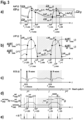
- the definitions of different types of pulsatility are as follows (see also Fig.
- the desired minimum pulsatility ⁇ AoP ⁇ h depends on the maximum and minimum desired aortic pressure AoP ⁇
- the pulsatility difference ⁇ AoP pulse ( h ) is defined to be the difference between the current physiologic (non-assisted) pulsatility ⁇ AoP( h ) and the desired (assisted) minimum pulsatility ⁇ AoP ⁇ h .
- the VAD is preferably a low inertia device.
- rotary blood pumps for example, such as the above-mentioned catheter-based pump, which have a negligibly small mass moment of inertia are perfectly suited for speed control scenarios with within-a-beat speed alterations, whilst being highly energy efficient, e.g. avoiding thermal dissipation losses.
- Particular characteristics for achieving the VAD having a small mass moment of inertia are, inter alia, i.e.
- moving, in particular rotating, parts of the VAD comprise low masses, for example a rotor or impeller may be made of a low weight material, such as plastic materials, synthetic materials; a driving means, such as an electric motor, is arranged near, preferably very near, most preferably adjacent, to the rotor or impeller, so that a shaft coupling the motor with the rotor or impeller can be kept short, thereby keeping the rotating mass thereof low (for instance, devices are known that have a rotating drive cable or wire for coupling a rotor to the motor, which would be undesirable as the mass of the cable or wire increases the mass to be accelerated or decelerated); all moving, in particular rotating, parts have small diameters, so that the resulting mass moment of inertia of the parts can be kept small.
- a driving means such as an electric motor
- a first aspect of the invention provides a control device which alters the rotational speed (in the following just "speed") n VAD (t) of a non-pulsatile VAD within a cardiac cycle with respect to physiological conditions in an event-based manner.
- control device can be configured to alter the speed of the VAD within a cardiac cycle of the assisted heart and, in combination with a trigger signal generator, to synchronize the alteration of a speed command signal n VAD (t) for speed with the heartbeat by using at least one event sequence that is related to at least one predetermined characteristic recurring event within the cardiac cycle.
- n VAD (t) a speed command signal
- the native cardiac output of the assisted heart can be affected by the VAD-induced blood flow Q VAD ( t ).
- An artery of interest may be at least the aorta, if the VAD is configured for left-sided heart assistance.
- an artery of interest may be at least the pulmonary artery, if the VAD is configured for right-sided heart assistance.
- control device may be configured to adjust the speed command signal n VAD set ( t ) of the VAD and to control the speed n VAD ( t ) of the VAD satisfying the desired minimum pulsatility ⁇ AoP ⁇ h either a first setup or a second setup.
- the control device can be arranged to adjust the speed command signal n VAD set (t) in an open-loop manner, e.g. by a command signal generator.
- the desired minimum pulsatility ⁇ AoP ⁇ h can be caused by alternating the speed command signal n VAD set ( t ) of the VAD between predefined speed levels using an event-based command signal generator.
- the control device can be arranged to adjust the speed command signal n VAD set (t) in a closed-loop feedback manner, e.g. by extending a speed control loop for the speed n VAD (t) of the VAD by an additional pressure control loop resulting in a cascade control strategy.
- the speed command signal n VAD set ( t ) may be automatically set in the speed command signal generator, e.g. by an outer loop with a feedback pressure control strategy, so that the desired minimum pulsatility ⁇ AoP ⁇ h can be achieved for the h th heartbeat while taking physiologically induced boundary conditions into consideration.
- the first setup may also take physiologically induced boundary conditions into consideration.
- Such boundary conditions may be e.g. limited available blood volume and/or maximum and/or minimum levels of mean arterial blood pressure AoP ( h ).
- AoP mean arterial blood pressure
- the open-loop setup (first setup) and the closed-loop setup (second setup) for the generation of the speed command signal n VAD set ( t ) may both be configured to operate in an event-based manner, and may both be intended to generate the desired minimum pulsatility ⁇ AoP ⁇ h during the h th heartbeat by adjusting the speed command signal n VAD set ( t ) of the VAD for the predetermined pulse duration ⁇ pulse ( h ).
- the control device may consist of an inner control loop for controlling the speed n VAD (t) of the VAD and an outer loop, the structure of which depends on the first or second setup defined above.
- an inner control loop for controlling the speed n VAD (t) of the VAD
- an outer loop the structure of which depends on the first or second setup defined above.
- n VAD (t) of the VAD for controlling the speed n VAD (t) of the VAD
- an outer loop the structure of which depends on the first or second setup defined above.
- control device is configured to synchronize the adjustment of the speed command signal n VAD set ( t ), such as the beginning and/or the end of a command signal pulse, with the heartbeat by using at least one sequence of trigger signals ⁇ (t) that is related to at least one predetermined characteristic event in the cardiac cycle.
- control device may be configured to adjust the speed command signal n VAD set ( t ) so that the blood pressure in the artery of interest produced by the VAD is increased for a predefined time interval of the cardiac cycle.
- control device may be configured to set the speed command signal n VAD set ( t ) for adjusting the VAD speed at a high level during systole and/or at a low level during diastole.
- the increase of the basic speed level n VAD set,basic ( h ) by adding a speed difference ⁇ n VAD set ( h ) generates a positive speed pulse during the systole of the
- the decrease of the basic speed level n VAD set,basic ( h ) by subtracting a speed difference ⁇ n VAD set ( h ) generates a negative speed pulse during the diastole of the assisted heart.
- speed command signal alteration during the systolic phase or the diastolic phase is respectively one generic example of synchronization of the speed variation with the heartbeat.
- desired minimum pulsatility ⁇ AoP ⁇ h may be generated by a combination of both a positive speed pulse during systole and a negative speed pulse during diastole.
- the reason for the speed command signal alteration to be synchronized with the cardiac cycle is to enhance the residual pulsatility of the weakened heart, which is due to the native heart contraction in systole.
- the speed command signal alteration results in systolic flow contribution to the native ejection of the heart alone; i.e. a co-ejection of the heart and the VAD is desirable.
- restoration and/or maintenance of the desired minimum pulsatility can be achieved by the control device being configured to alter the speed command signal n VAD set ( t ) for adjusting the speed of the VAD so that the VAD-induced blood flow Q VAD ( t ) is reduced substantially during the diastole of the cardiac cycle and/or is increased substantially during the systole of the cardiac cycle.
- the desired minimum pulsatility of the arterial blood pressure can be restored and maintained.
- the diastolic speed reduction of the VAD may allow the ventricle to fill adequately, so that a systolic co-ejection of blood volume from the VAD and the native heart is possible.
- the native heart and the VAD both preferably provide adequate systolic peak flow rates so that the total peak flow per heartbeat Q total
- max h Q heart
- max h and the total ejected volume (EV) per heartbeat EV h EV heart h + EV VAD h result in an adequate increase in systolic systemic blood pressure.
- the native heart's ability to co-eject may depend on the ventricular preload, on the ventricular filling level, and on the level of heart contractility as well as on the achievable peak flow of the VAD.
- the native heart's ability to co-eject may also depend on the patient's body mass index, or body surface, or the vascular compliance as well as the peripheral resistance.
- a generic patient with a height of 1.75 m and a weight of 75 kg has approximately a mean blood flow of 5 L/min.
- the demand can be estimated based on a person's body surface area (BSA) .
- the generic patient has a body surface area of about 1.9 m 2 (based on the formula by R. D. Mosteller, "Simplified calculation of body-surface area", N. Engl. J. Med. 317, No. 17, October 1987, p. 1098 ).
- the normal blood flow normalized to the BSA equals approximately 2.6 L/m 2 .
- a mean blood flow of 5 L/min in a healthy patient at rest results in a blood pressure of about 120 mmHg to 80 mmHg.
- max (h) of about 8 L/min during systole is considered sufficient to result in a desired minimum pulsatility ⁇ AoP ⁇ h of about 15 mmHg in a normal-sized person (BSA 1.9 m 2 ).
- BSA normal-sized person
- a total peak flow of 8 L/min divided by 1.9 m 2 and multiplied by the patient's actual BSA may result in a more patient-adapted value of peak flow.
- max (h) 6.7 L/min total peak flow during systole.
- a total peak flow between 6 L/min and 10 L/min should be sufficient for the vast majority of patients treated with an assist device to gain a target desired minimum pulsatility of at least ⁇ AoP ⁇ h ⁇ 15 mmHg .
- the desired minimum pulsatility ⁇ AoP ⁇ h will not be a fixed value, but may vary based on the recruitment of vWF. Simulation results have underlined the fact that the command signal generator or the outer pressure control loop can either focus on increased pulsatility while accepting reduced mean aortic pressure or focus on increased mean aortic pressure while accepting reduced pulsatility.
- the predetermined pulse duration ⁇ pulse (h) of the speed pulse may be in the range of +/- 50 % or +/- 100 ms of the duration of the systole ⁇ Systole (h) of the assisted heart.
- the pulse duration of the speed pulse may also be adapted to the heart rate, resulting in a time interval ⁇ assist (h) , which preferably depends e.g. on the observations of preceding heart rates and the durations of preceding systolic phases.
- the adjustment of the speed command signal n VAD set (t) may be synchronized with the appearance of the R wave in an electrocardiogram (ECG) signal of the patient and/or set to a constant repetition rate e.g. in the case of cardiac arrest.
- ECG electrocardiogram
- the VAD e.g. in the form of a rotational blood pump
- the VAD may comprise an actuator, for instance a rotational motor, for driving the blood pump, which produces the VAD-induced blood flow Q VAD (t) .
- the control device may alter the speed n VAD (t) of the VAD by adjusting the speed command signal n VAD- set (t) to the target speed level for the rotational motor and controlling the speed n VAD (t) of the VAD by a feedback closed-loop control. Accordingly, the modification of the pulsatility, i.e.
- the pulsatility difference ⁇ AoP pulse (h) may be associated with a corresponding adjustment of the speed command signal n VAD set (t) , e.g. by a speed difference ⁇ n VAD set (h) , i.e. the speed command signal n VAD set (t) of the rotational motor is increased from a basic speed level n VAD set,basic (h) by the speed difference ⁇ n VAD set (h) for generating the desired minimum pulsatility ⁇ AoP ⁇ h which is set by the control device.
- a speed difference ⁇ n VAD set (h) i.e. the speed command signal n VAD set (t) of the rotational motor is increased from a basic speed level n VAD set,basic (h) by the speed difference ⁇ n VAD set (h) for generating the desired minimum pulsatility ⁇ AoP ⁇ h which is set by the control device.
- the speed difference ⁇ n VAD set (h) may also be negative, e.g. to generate a negative speed pulse.
- a desired speed difference ⁇ n VAD set (h) may be determined based on the achieved pulsatility difference ⁇ AoP pulse (h) , which is largely a function of how much blood volume is delivered to the arterial system in a given time unit. It needs to be understood that any arterial blood pressure built-up is the end result of blood volume being ejected during a time unit into the arterial system with its intrinsic compliance and peripheral resistance.
- control device is further configured to adjust the speed command signal n VAD set (t) also outside the speed alteration interval, e.g. to adjust the basic speed level n VAD set,basic (h) , so that a predetermined mean arterial blood pressure AoP ( h ) is achieved by the VAD or to avoid any backflow into the ventricle via the pump, which is called regurgitant pump flow.
- control device in particular in the second closed-loop setup, may be configured to adjust the speed command signal n VAD set (t) both within and outside the speed alteration interval to achieve the desired minimum pulsatility ⁇ AoP ⁇ h .
- control device may additionally be configured to adjust the speed command signal n VAD set (t) while taking into consideration the mean arterial blood pressure per heartbeat AoP ( h ) as a control constraint.
- control device may be configured to adjust the speed command signal n VAD set (t) to avoid a drop of the mean arterial blood pressure AoP ( h ) below a predetermined threshold value AoP thr ( h ).
- control device may be configured to adjust the speed command signal n VAD set (t) so that the speed alteration interval (or speed pulse) is started at a predetermined time interval ⁇ incr (h) before a predetermined characteristic event occurs.
- the speed change may be induced a time interval ⁇ incr (h) before, e.g., an expected or predicted beginning of the ventricular contraction of the assisted heart, which may be the corresponding characteristic event in the cardiac cycle.
- This may be of particular importance, since the dynamic response of a particular VAD, e.g. a specific pump, may be delayed due to a pump-specific mechanical and/or hydraulic inertia requiring a latency before the desired effect is provided.
- the beginning of the heart contraction which is defined e.g. by the time of mitral valve closure, may be detected based on a corresponding blood pressure signal.
- a corresponding blood pressure signal For example, if the VAD is configured for left-sided heart assistance the corresponding blood pressure signal may be the left ventricular pressure.
- the atrial contraction preceding the ventricular contraction may be detected.
- the event occurs earlier then the event of systolic contraction, allowing the pump to speed up when the beginning of atrial contraction is used as the event.
- the predetermined event may be the occurrence of the R-wave in an ECG signal of the assisted heart.
- the time interval ⁇ incr (h) may be useful for taking account of the fact that the speed increase of the VAD is slowed down by hydraulic impacts of the blood on the drive of the VAD.
- the speed command signal n VAD set (t) should be increased by a smooth trajectory to avoid hemolysis or other undesired hemodynamic side effects, such as suction or VAD-induced cavitation, when blood would be accelerated too fast.
- control device may be configured to end the pulse of the speed command signal n VAD set (t) after the predetermined pulse duration ⁇ pulse (h) .
- control device may be configured to end the pulse of the speed command signal n VAD set (t) after a heart rate dependent pulse duration ⁇ assist (h) , i.e a pulse duration that is adapted by the control device to the heart rate HR(h).
- control device may be configured to end the pulse of the speed command signal n VAD set (t) when at least one predetermined characteristic event of the cardiac cycle occurs.
- control device may be configured to end the pulse of the speed command signal n VAD set (t) a predetermined time interval ⁇ red (h) before or when at least one predetermined characteristic event of the cardiac cycle occurs.
- the predetermined characteristic event may be the beginning of the relaxation of the assisted heart and/or the closing of the aortic valve.
- At least one event may be the beginning of relaxation of the assisted heart.
- the control device may be configured to derive the occurrence of an event based on a signal that comprises information about characteristic events such as the beginning of relaxation.
- the pulse of the speed command signal n VAD set (t) can be synchronized e.g. with the time of occurrence of the maximum drop in pressure within the ventricle of the assisted heart. Note that the time of maximum drop in pressure marks the beginning of ventricular relaxation (relaxation moment) after the preceding systole.
- control device may be configured to derive the occurrence of at least one event per cardiac cycle based on at least one internal signal of the control device.
- "Internal signal" of the control device means herein that the signal is a signal which is already internally available to the control device for analysis, such as a control signal provided by the control device to the VAD.
- the at least one internal signal may be an electrical current provided to actuate the VAD, such as a motor current supplied to the VAD.
- the control device may be configured to derive the occurrence of at least one event per cardiac cycle based on the analysis of the electrical current signal and/or a processed version thereof, for example a time derivative, e.g. the first time derivative.
- the VAD may be the above-mentioned rotational blood pump.
- the blood pump may comprise an actuator, such as a rotational electrical motor, for driving a rotational thrust element, such as an impeller, for producing a corresponding blood flow.
- a motor current is consumed by the motor in order to achieve a respective target speed level, according to the set speed command signal n VAD set (t) , of the motor and the rotational thrust element.
- the motor current supplied to the VAD by the control device or by a supply unit controlled by the control device can be used as an internal signal to derive the occurrence of at least one event per cardiac cycle.
- control device may be further configured to estimate the current VAD-induced blood flow Q VAD (t) , which is based on the electrical current signal and on known calculation specifications with a pump characteristic correlation between motor current at a given speed, pump flow and pressure difference.
- control device may be configured to derive the occurrence of at least one event per cardiac cycle from at least one external signal provided to the control device.
- External signal means herein that the signal is a signal which is received by the control device from external sensors such as one or more blood pressure sensors of the VAD and/or from external devices such as a patient monitoring unit or an electrocardiograph (ECG).
- ECG electrocardiograph
- Such external signals can be fed into the control device via corresponding interfaces or input terminals, to be available in the control device for processing and/or analysis by the control device.
- the measuring signal may represent at least one of a blood pressure difference ⁇ p (t) between an outlet of the VAD and an inlet of the VAD, a blood pressure in a ventricle of the assisted heart LVP (t) , a blood pressure in the aorta AoP (t) adjacent to the assisted heart, a blood pressure in the vena cava CVP (t) adjacent to the assisted heart, a blood pressure in the pulmonary artery PAP (t) adjacent to the assisted heart, just to give some examples.
- the waveforms of all of these measuring signals may contain information descriptive of the time of occurrence of particular characteristic events in the cardiac cycle.
- the VAD is the above-discussed rotational blood pump, it may comprise an inlet for sucking in blood from the heart, e.g. from the inside of a ventricle, and an outlet for ejecting blood to a vessel adjacent to the heart, such as the artery of interest, which may be the aorta or pulmonary artery depending on whether the VAD is inserted to the left side or the right side of the heart.
- a vessel adjacent to the heart such as the artery of interest, which may be the aorta or pulmonary artery depending on whether the VAD is inserted to the left side or the right side of the heart.
- the VAD may comprise at least one of a pressure sensor for measuring the blood pressure at the inlet of the VAD, such as a ventricular pressure in the assisted heart, and a pressure sensor for measuring the blood pressure in a vessel adjacent to the heart, such as the blood pressure in the aorta or pulmonary artery adjacent to the assisted heart.
- the VAD may comprise one differential pressure sensor for measuring the differential blood pressure between the outlet and the inlet of the VAD.
- control device may be configured to receive, store and analyze at least one measuring signal which contains information about characteristic points of the cardiac cycle, and which can be used to estimate the current working phase of the heart in the cardiac cycle. Then, the control device may be configured to predict the time of re-occurrence of a particular characteristic during the next cardiac cycle based on information about previous cardiac cycles.
- the at least one measuring signal may be at least one of an ECG signal, a measuring signal representing the blood pressure in the left ventricle or the right ventricle of the heart, a measuring signal of the blood pressure in the vena cava or the aorta or in the pulmonary artery adjacent to the heart.
- the chosen signal may preferably contain information about the cardiac cycle, so that the time of occurrence of at least one event per cardiac cycle can be predicted based on the chosen measurement signal and on detected events during previous cardiac cycles.
- control device may be configured to eliminate the effect of active heart assistance by the VAD on the measuring signals from said measuring signals.
- control device may be configured to analyze at least two, preferably independent, measuring signals by data fusion with the aim of detecting the predetermined events in a cardiac cycle despite the effect of the VAD-induced pressure change on the cardiac dynamic behavior.
- control device may be configured to set the speed of the VAD so that in the diastolic phase of the cardiac cycle of the assisted heart the amount of blood ejected by the VAD into the artery of interest, such as the aorta or the pulmonary artery, is low enough such that a blood volume remains in the corresponding ventricle and the co-ejection of the VAD and the ventricle during systole results in a preferred minimum peak blood flow, i.e. the minimum peak blood flow is preferably about 6 L/min, more preferably 7 L/min, most preferably 8 L/min and more (as discussed above).
- the systolic peak flow will largely depend on the native heart's ability to co-eject, depending specifically on the ventricular preload, the ventricular filling level, and the level of heart contractility as well as the achievable peak flow of the VAD.
- max (h) and the total ejected volume per heartbeat EV (h) will need to result in an adequate increase in systolic systemic blood pressure, as described above. This, however, also depends on the patient's body mass index, or body surface, the vascular compliance as well as peripheral resistance.
- control device may be configured to adjust the speed command signal n VAD set (t) in the form of a pulse during the cardiac cycle only if the resulting mean arterial blood pressure per heartbeat AoP ( h ) does not drop below a predetermined threshold value AoP thr ( h ).
- the minimum VAD-induced blood flow Q VAD (h) may correspond to a required minimum heart assistance to be provided by the VAD to a weakened heart.
- the idea is that the VAD can be operated so as both to obtain the desired recruitment of vWF and to ensure that a required minimum blood flow is provided.
- currently required blood flow may be related to a patient's current perfusion demand, taking into consideration periods of required high assistance, e.g. daytime activity, walking, climbing stairs, and so on, in which case the VAD will run at relatively high mean speeds.
- Periods of low patient perfusion demands, e.g. at rest, while sleeping, etc. can be used to run the VAD at lower mean speeds.
- control device may be configured to use any available surplus between a currently required minimum blood flow and the maximum blood flow that the VAD may provide for the restoration and maintenance of a residual pulsatility as proposed here.
- a speed pulse aiming to restore or maintain a desired minimum pulsatility may be induced in a one in two or one in three or one in four manner or in a two in three or two in four or two in five manner, i.e. in one cardiac cycle in every two or in every three or in every four consecutive cardiac cycles and in two cardiac cycles in every three or in every four or in every five consecutive cardiac cycles, respectively. This may be particular beneficial if the heart frequency is too high or if the level of pump assistance for the heart is not adequate.
- control device can additionally be configured to set the speed n VAD (t) of the VAD, during at least y of the other ( x-y ) consecutive cardiac cycles of the assisted heart so that the mean arterial blood pressure per heartbeat remains above the predetermined threshold value ( AoP ( h ) ⁇ AoP thr ( h )).
- control device can be implemented by a corresponding computing unit, in hardware or software or any combination thereof, of the control device.
- Such computing unit can be configured by means of corresponding computer programs with software code for causing the computing unit to perform the respectively required control steps.
- a programmable computing unit is well known in the art and to the person skilled in the art and therefore need not be described here in detail.
- the computing unit may comprise particular dedicated hardware useful for particular functions, such as one or more signal processors for processing and/or analyzing e.g. the discussed measuring signals.
- respective units for controlling the speed of a drive of the VAD may be implemented by respective software modules as well.
- the corresponding computer programs can be stored on a data carrier containing the computer program.
- the computer program may be transferred, e.g. via the Internet, in the form of a data stream comprising the computer program without the need of a data carrier.
- a second aspect of the invention provides a VAD comprising one of the control devices according to the first aspect of the invention.
- the VAD may be a rotational blood pump, i.e. a blood pump driven by a rotational motor.
- such blood pump may be catheter-based to be implanted or placed directly into a heart via corresponding blood vessels.
- the VAD may be a blood pump as published e.g. in US 5 911 685 , which is particularly arranged for a temporary placement or implantation into the left or right heart of a patient.
- the VAD is a low inertia device by comprising, but not being limited to, one or more of the following characteristics: (1) moving, in particular rotating, parts, for example a rotor or impeller, of the VAD may comprise low masses by being made of a low weight material, such as plastic materials, synthetic materials; (2) a driving means, such as an electric motor, may be arranged near, preferably very near, most preferably adjacent, to a part, for example a rotor or impeller, driven by the motor, and, if catheter-based, should preferably not include any rotational drive cable or drive wire, but electric wiring; (3) a coupling or connection, for example a shaft, of the motor with a part, for example a rotor or impeller, driven by the motor may be made short; (4) all moving parts, in particular rotating parts, of the VAD may have small diameters. Note that the foregoing list of characteristics does not claim to be complete, i.e. the device may comprise further or alternative characteristics that make the device a low
- FIG 1 shows a catheter-based rotational blood pump (in the following called “blood pump”) on the left hand side, which is described herein as one exemplary embodiment of a VAD.
- blood pump catheter-based rotational blood pump
- the blood pump is based on a catheter 10 (catheter-based blood pump), by means of which the blood pump is temporarily introduced through the aorta 12 and the aortic valve 15 into the left ventricle 16 of a heart.
- the blood pump comprises in addition to the catheter 10 a rotary pumping device 50 fastened to the end of a catheter tube 20.
- the rotary pumping device 50 comprises a motor section 51 and a pump section 52 located at an axial distance therefrom.
- a flow cannula 53 is connected to the pump section 52 at its one end, extends from the pump section 52 and has an inflow cage 54 located at its other end.
- the inflow cage 54 has attached thereto a soft and flexible tip 55.
- the pump section 52 comprises a pump housing with outlet openings 56.
- the pumping device 50 comprises a drive shaft 57 protruding from the motor section 51 into the pump housing of the pump section 52.
- the drive shaft 57 drives an impeller 58 as a thrust element by means of which, during operation of the blood pump, blood can be sucked through the inflow cage 54 and discharged through the outlet openings 56.
- the pumping device 50 can also pump in the reverse direction when adapted accordingly, e.g. as required when the blood pump is placed in the right heart.
- Figure 1 shows the rotary blood pump as one particular example of a VAD located in and for assistance of the left heart.
- the rotary blood pump of the present example may be temporarily introduced into the right heart from the vena cava and located in the right heart so that blood can be ejected into the pulmonary artery.
- the blood pump may be configured for sucking in blood from the vena cava or from the right ventricle and for ejecting the blood into the pulmonary artery. That is to say, the principles and functionalities described by the one particular embodiment may be transferred correspondingly for right-sided heart assistance. Thus, no detailed description is required.
- the signal lines 28A, 28B are parts of blood pressure sensors with corresponding sensor heads 30 and 60, respectively, which are located externally on the housing of the pump section 52.
- the sensor head 60 of the first pressure sensor is associated with signal line 28B.
- the signal line 28A is associated with and connected to the sensor head 30 of the second blood pressure sensor.
- the blood pressure sensors may, for example, be optical pressure sensors functioning according to the Fabry-Pérot principle as described in US 5 911 685 A , in which case the two signal lines 28A, 28B are optical fibers. However, other pressure sensors may be used instead.
- signals of the pressure sensors which carry the respective information on the pressure at the location of the sensor and which may be of any suitable physical origin, e.g.
- the pressure sensors are arranged so that the aortic pressure AoP (t) is measured by sensor head 60 and the left ventricular pressure LVP (t) is measured by sensor head 30.
- the data processing unit 110 is configured for acquisition of all external and internal signals, for actual signal processing, which includes for example calculation of a difference between two pressure signals as a basis for estimating pump flow, for signal analysis to detect characteristic events during the cardiac cycle based on the acquired and calculated signals, and for generating a sequence of trigger signals ⁇ (t) by means of a trigger signal generator, for triggering a speed command signal generator 120 (see details below).
- the data processing unit 110 is connected via corresponding signal lines to additional measurement devices 300, such as a patient monitoring unit 310 and an electrocardiograph 320; these devices are just two examples, i.e. other measuring devices may provide useful signals and therefore be used as well.
- the electrocardiograph 320 provides an ECG signal ECG (t) to the data processing unit 110.
- the control device 100 further comprises a user interface 200 comprising a display 210 and a communication interface 220. On the display 210, setting parameters, monitored parameters, such as measured pressure signals, and other information is displayed. Further, by means of the communication interface 220, the user of the control device 100 can communicate with the control device 100, e.g. to change settings of the whole system.
- the data processing unit 110 is particularly configured to derive or predict the time of occurrence of one or more predefined characteristic events during the cardiac cycle of the assisted heart by means of real-time analysis of current signal values which are used for generation of a sequence of trigger signals ⁇ (t) by means of a trigger signal generator.
- the resulting sequence of trigger signals ⁇ (t) is forwarded to the speed command signal generator 120 to trigger speed command signal changes.
- the data processing unit 110 is configured to analyze previous values of these speed command signals n VAD set (t) , as well. That is, the data processing unit 110 is also configured to predict the time of occurrence of the at least one predefined characteristic event in the upcoming cardiac cycle based on the stored information about the characteristic events occurring during the current and/or previous cardiac cycles.
- One particular characteristic event of the cardiac cycle may be the beginning of contraction of the heart at the beginning of the systolic phase.
- the detected occurrence or the predicted occurrence of such characteristic event is used as an event for synchronizing the pulse of the speed command signal n VAD set (t) as proposed herein with the cardiac cycle.
- the speed command signal generator 120 is configured to generate and adjust the speed command signal n VAD set (t) of the pumping device 50 and to provide it to a speed control unit 130 either in a feedforward setup as an event-based command signal generator (first setup) or in an outer feedback closed-loop setup for pressure control (second setup).
- the speed command signal generator 120 is triggered by at least one sequence of trigger signals ⁇ (t) which is provided by the data processing unit 110.
- the speed command signal n VAD set (t) is provided by a pressure control algorithm (as the command signal generator 120) which operates in an outer feedback loop and is fed with external and internal signals by the data processing unit 110, and triggered by at least one sequence of trigger signals ⁇ (t) provided by the data processing unit 110 to achieve the desired minimum pulsatility ⁇ AoP ⁇ h .
- the speed control unit 130 controls the speed n VAD (t) of the VAD, in accordance with the speed command signal n VAD set (t) , by supplying a motor current I VAD (t) to the motor section 51 of the pumping device 50 via the power-supply line 29 that leads through the catheter tube 20.
- the current level of the supplied motor current I VAD (t) corresponds to the electrical current currently required by the pumping device 50 to establish the target speed level as defined by the speed command signal n VAD set (t) .
- the pump Via the power-supply line 29, the pump also communicates with the control unit 100.
- a measuring signal such as the supplied motor current I VAD (t) which is used as a representative signal of an internal signal of the control device 100 is provided to the data processing unit 110 for further processing.
- control device 100 is configured for altering the speed of the blood pump of Figures 1 and 2 as an exemplary embodiment of a VAD for heart assistance.
- the control device 100 is particularly configured to alter the speed of the blood pump 50 within a cardiac cycle of the assisted heart, resulting in a change of the blood flow through the pump, the speed alteration of which is synchronized with the heartbeat by means of at least one event per cardiac cycle which is related to a predetermined event in the cardiac cycle. That is to say, the speed command signal generator 120 may be triggered by at least one sequence of trigger signals ⁇ (t) provided by the trigger signal generator of the data processing unit 110 which obtains information on at least one particular event in the cardiac cycle the occurrence of which is detected, the corresponding signal information being used to set the sequence of trigger signals ⁇ (t).
- the trigger signal generator which provides the sequence of trigger signals ⁇ (t) may rely on more than one event in the cardiac cycle to be detected during each cardiac cycle and to be analyzed to derive a corresponding sequence of trigger signals ⁇ (t) for adjusting the command signal n VAD set (t) and, thus, for altering the speed n VAD (t) of the blood pump 50.
- the blood pump comprises the rotary pumping device 50, with the (rotational) speed n VAD (t) of the impeller being controlled by speed control unit 130.
- the speed command signal n VAD set (t) of the blood pump is adjusted by the command signal generator 120.
- the control device 100 in particular the speed command signal generator 120, is configured to adjust the speed command signal n VAD set (t) of the rotary pumping device 50 so that the resulting speed n VAD (t) of the VAD is altered to generate a VAD-induced blood flow Q VAD (t) , which induces a pressure pulse within each cardiac cycle.
- Figure 3 shows a diagram with exemplary waveforms.
- the waveforms in Figure 3a represent the aortic pressure signal distinguishing between physiological (non-assisted) aortic pressure AoP (t) (dashed line) and desired (assisted) aortic pressure AoP ⁇ t (solid line).
- the waveform in Figure 3b represents the signal for the left ventricular pressure LVP(t) with examples for characteristic pressure values and/or events in the cardiac cycle which may be used for generating or deriving a sequence of trigger signals ⁇ (t).
- the waveform in Figure 3c represents an ECG signal.
- FIG. 3 illustrates by way of one example the principle of a pulsatile blood pressure restoration and maintenance using the blood pump of Figures 1 and 2 under control of the control device 100 in Figure 1 .
- Figure 3d shows one particular example of a speed command signal n VAD set (t) .
- the speed command signal n VAD set (t) is used for the pump speed alteration which corresponds to the signal output of the speed command signal generator 120, and which is forwarded to the speed control unit 130.
- the sequence of trigger signals ⁇ (t) is the basis for the event-based speed command signal generation or the event-based closed-loop pressure control resulting in an altered speed command signal n VAD set (t) , the alteration of which is synchronized with the heartbeat.
- the speed decrease is triggered so that a the pulse of the speed command signal n VAD set (t) after a heart rate dependent pulse duration ⁇ assist (h) , i.e. the pulse duration is adapted to the heart rate HR (h) . That is to say, the command signal generator 120 is configured to generate a speed pulse with a heart rate dependent pulse duration.
- the speed decrease can be triggered so that a predetermined pulse duration ⁇ pulse (j) is achieved.
- the command signal generator 120 can be configured to generate a speed pulse with a predetermined pulse duration ⁇ pulse (j) .
- the speed increases by the speed difference ⁇ n VAD set (j) at the beginning of the speed pulse ends here e.g. at time point t LVP j,ED , and the speed decrease at the end of the speed pulse ends here e.g. at time point t AoP j,ES .
- the speed command signal generator 120 is configured to control pulsatility ⁇ AoP( h ) by adjusting the speed difference ⁇ n VAD set ( h ) accordingly.
- the data processing unit 110 is configured to measure and/or calculate the current mean arterial blood pressure per heartbeat AoP ( h ) and to supply the current value to the speed command signal generator 120.
- the speed command signal generator 120 is further configured to adjust the speed command signal n VAD set (t) to preferably avoid a drop of the arterial blood pressure below a predetermined threshold value AoP ( h ) ⁇ AoP thr ( h ).
- restoration and/or maintenance of a sufficient minimum blood pressure pulsatility can be achieved by altering the speed of the rotary pumping device 50 so that the VAD-induced blood flow Q VAD (t) is reduced substantially during diastole of the cardiac cycle and/or is increased substantially during systole of the cardiac cycle.
- the speed command signal generator 120 is configured to adjust the speed command signal n VAD set (t) so that in the diastolic phase of the cardiac cycle of the assisted heart the blood volume ejected to the aorta (or pulmonary artery) is low such that a predetermined volume remains in the left (right) ventricle and the rotary pumping device 50, together with the left (right) ventricle, co-ejects appropriate blood volumes during systole.
- the diastolic speed reduction also allows the heart to fill adequately, so that a systolic co-ejection of blood from the rotary pumping device 50 and the native heart is possible.
- the inventors have found that the pump and the native heart should induce a total peak flow during systole of Q total
- max h Q heart
- the inventors have validated the values stated for peak flows per heartbeat of the pump Q pump
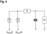
- the model used is illustrated in Figure 4 .
- Figure 4 shows the circuit of the electrical model approximating the dynamics of the so-called Windkessel effect in the aorta when blood is ejected by the heart.
- the (residual) cardiac output Q heart ( h ) and the blood flow of the pump Q pump ( h ) are assumed as current sources.
- Figure 5 represents the results of five different simulation scenarios.
- the table below shows the results of the five different simulation scenarios with additional information on total blood flow for a heartbeat j (Q total (j) ) and corresponding pulsatility ( ⁇ AoP (j) ).
- the simulation results underline the fact that the speed alteration can either focus on increased pulsatility while accepting reduced mean aortic pressure or focus on increased mean aortic pressure while accepting reduced pulsatility.
- Physical and physiological constraints were taken into consideration here, such as very low inertia and hemolysis.
- the data processing unit 110 is configured to trigger the speed command signal generator 120 so that the pulse of the speed command signal n VAD set (t) begins and/or ends at the detected or predicted time of occurrence of at least one predetermined event in the cardiac cycle.
- the at least one sequence of trigger signals ⁇ (t) which is generated by the trigger signal generator of the data processing unit 110 is provided to the speed command signal generator 120.
- the speed command signal generator 120 is configured to initialize the increase of the speed command signal n VAD set (t) a predetermined time interval ⁇ incr (h) before a characteristic event of the cardiac cycle occurs, which is used as a basis for generating the sequence of trigger signals ⁇ (t).
- This sequence of trigger signals ⁇ (t) can be used to change the pump speed in a moderate manner to avoid suction, blood damage, etc., or to allow the pump speed increase in a timely manner to address the phase shift between a change in speed and the resulting change in pressure (compliance of vasculature and inertia of blood) for the systolic co-ejection.
- the starting time of contraction of the left ventricle is used as the characteristic time taken into account for the sequence of trigger signals ⁇ (t) generated by the trigger signal generator.
- the contraction of the left ventricle starts immediately after the R-wave occurs in the corresponding ECG signal.
- the speed command signal generator 120 may be configured to derive a sequence of trigger signals ⁇ (t) based on the ECG signal, which is provided to the data processing unit 110.
- the data processing unit 110 may be configured to receive the ECG signal from an (external) ECG device 320 and to generate the sequence of trigger signals ⁇ (t) by means of the trigger signal generator.
- another measuring signal may be used by the data processing unit 110 for generating the sequence of trigger signals ⁇ (t), showing e.g. the beginning of left atrial contraction which can be used as an event, the time of occurrence of which precedes the beginning of the systolic ejection phase.
- some characteristic values and times are marked as examples on the signal for the left ventricular pressure LVP (t) , namely the minimum value LVP min ( j ), the maximum value LVP min ( j ), its maximum change over time dLVP( j )/dt
- the speed command signal generator 120 synchronizes the adjustment of the speed command signal n VAD set (t) with the cardiac cycle by means of at least one sequence of trigger signals ⁇ (t) which is provided by the data processing unit 110 such that the speed pulse is initialized before the beginning of ventricular contraction and/or the occurrence of the R-wave in the ECG signal.
- the inventors have further found that it can be ensured by the predetermined time interval ⁇ incr (h) that the blood flow is not accelerated too fast, which is assumed to reduce the likelihood of blood damage and/or of undesired hemodynamic effects.
- the speed command signal generator 120 is configured to adjust the speed command signal n VAD set (t) such that the speed n VAD (t) of the VAD is altered smoothly.
- Figure 3d shows a speed command signal n VAD set (t) with a ramp for increasing or decreasing the speed n VAD (t) of the VAD linearly, but other forms may be possible as well, such as an exponential speed increase or decrease.
- the speed command signal generator 120 is configured to adjust the speed n VAD (t) of the VAD back to the initial speed level n VAD set,basic (t) to end a current speed pulse after the predetermined pulse duration ⁇ pulse (h).
- the speed command signal generator 120 is configured to adjust the speed command signal n VAD set (t) for altering the speed n VAD (t) of the VAD to end a current speed pulse when a predetermined characteristic event of the cardiac cycle occurs.
- the predetermined event is the beginning of relaxation of the assisted heart and/or the closing of the aortic valve.
- the predetermined time interval ⁇ red (h) for initializing the reduction of the speed command signal n VAD set (t) before, during or after a predetermined characteristic event in the cardiac cycle may also be taken into account.
- the trigger for terminating the speed pulse is part of the sequence of trigger signals ⁇ (t) and is provided by the data processing unit 110 a time interval ⁇ red (h) before ventricular relaxation begins.
- this trigger signal is based on a prediction of the beginning of ventricular relaxation detected during previous cardiac cycles.
- the closing of the aortic valve can be determined when the left ventricular pressure LVP (t) drops below the aortic pressure AoP (t) or, correspondingly, when the pressure difference between the inlet 54 and the outlet 56 of the flow cannula 53 becomes lower than zero.
- the data processing unit 110 is further configured to derive the sequence of trigger signals ⁇ (t) from at least one signal that comprises information relating to the closing of the aortic valve of the assisted heart as a characteristic event in the cardiac cycle.
- useful signals may be a measuring signal representing a left ventricular pressure LVP(t) of the assisted heart and/or the aortic pressure AoP(t) adjacent to the assisted heart.
- the signal may be a measuring signal representing a blood pressure in the vena cava CVP(t) adjacent to the assisted heart and/or right ventricular pressure RVP(t) and/or a blood pressure in the pulmonary artery PAP(t) adjacent to the assisted heart.
- the data processing unit 110 is configured to derive a sequence of trigger signals ⁇ (t) from a required motor current I VAD (t) that is provided by the speed control unit 130 to the rotary pumping device 50.
- the required motor current I VAD (t) reflects the energy required by the rotary pumping device 50 to follow the set speed value.
- the command signal generator 120 may be triggered by a corresponding sequence of trigger signals ⁇ (t) provided by the data processing unit 110.
- the data processing unit 110 is configured to receive, store and analyze at least one measuring signal containing characteristic information of the circulatory system and of the cardiac cycle in order to predict at least one event per heartbeat based on analysis results of previous cardiac cycles. Most preferably, the data processing unit 110 is configured to analyze at least two measuring signals to filter the impact of the pump-induced pressure changes so that characteristic events in the cardiac cycle may be reliably detected.
Claims (15)
- Steuervorrichtung (100) zum Steuern der Rotationsgeschwindigkeit (n VAD (t)) einer nicht-pulsierenden ventrikulären Unterstützungsvorrichtung, VAD, (50) mittels einer ereignisbasierten Innerhalb-eines-Taktes-Steuerstrategie, wobei die Steuervorrichtung (100) dazu eingerichtet ist, die Rotationsgeschwindigkeit (n VAD (t)) des VAD (50) innerhalb des Herzzyklus (h) des unterstützten Herzens zu ändern und die Änderung der Rotationsgeschwindigkeit (n VAD (t)) mit dem Herzschlag durch mindestens eine Sequenz von Triggersignalen (σ(t)) zu synchronisieren, die mit mindestens einem vorbestimmten charakteristischen Ereignis im Herzzyklus in Beziehung steht, wobei die Steuervorrichtung (100) so konfiguriert ist, dass sie die Rotationsgeschwindigkeit (n VAD (t)) des VAD (50) ändert, um eine gewünschte minimale Pulsatilität (


- Steuervorrichtung (100) nach Anspruch 1, wobei die Steuervorrichtung (100) dazu eingerichtet ist, die Drehzahl (n VAD (t)) des VAD (50) für eine vorbestimmte Pulsdauer (τpulse (h)) oder eine herzfrequenzabhängige Pulsdauer (τassist (h)) zu ändern, um eine vorbestimmte gewünschte minimale Pulsatilität (

- Steuervorrichtung (100) nach Anspruch 2, wobei die Steuervorrichtung (100) dazu eingerichtet ist, ein Geschwindigkeitsbefehlssignal (n VAD set (t)) für die Änderung der Drehzahl (n VAD (t)) des VAD (50) zu erzeugen, so dass die vorbestimmte gewünschte minimale Pulsatilität (
 entweder in einem ersten Aufbau durch eine offene Regelung, wobei das Drehzahlbefehlssignal (n VAD set (t)) unter Verwendung eines Befehlssignalgenerators (120) zwischen vorgegebenen Drehzahlstufen gewechselt wird,oder in einem zweiten Aufbau durch eine geschlossenes Druckregelung in einem Rückkopplungssystem, wobei das Drehzahlbefehlssignal (n VAD set (t)) automatisch für jeden Herzschlag (h) eingestellt wird,wobei vorzugsweise die Steuervorrichtung (100) dazu eingerichtet ist, das Drehzahlbefehlssignal (n VAD set (t)) so einzustellen, dass in dem zweiten Aufbau die vorgegebene gewünschte minimale Pulsatilität(
- Steuervorrichtung (100) nach Anspruch 2 oder 3, wobei die Steuervorrichtung (100) dazu eingerichtet ist, die Rotationsgeschwindigkeit (n VAD (t)) des VAD (50) zu ändern, um die vorbestimmte gewünschte minimale Pulsatilität (

wobei vorzugsweise die Steuervorrichtung (100) dazu eingerichtet ist, die Drehzahl (n VAD (t)) des VAD (50) während mindestens y der anderen x minus y aufeinanderfolgenden Herzzyklen des unterstützten Herzens so einzustellen, dass der mittlere arterielle Blutdruck pro Herzschlag (AoP (h)) über dem vorbestimmten Schwellenwert (AoP thr(h)) bleibt. - Steuervorrichtung (100) nach einem der Ansprüche 2 bis 4, wobei die Steuervorrichtung (100) weiter dazu eingerichtet ist, das Drehzahlbefehlssignal (n VAD set (t)) so einzustellen, dass ein mittlerer arterieller Blutdruck pro Herzschlag (
AoP (h)) über einem vorbestimmten Schwellenwert (AoP thr(h)) bleibt. - Steuervorrichtung (100) nach einem der Ansprüche 2 bis 5, wobei die Steuervorrichtung (100) dazu eingerichtet ist, eine Anpassung des Drehzahlbefehlssignals (nVAD set(t)) eines vorbestimmten ersten Zeitintervalls (τincr (h)) vor dem Auftreten eines der mindestens einen vorbestimmten charakteristischen Ereignisse zu initialisieren, wobei das charakteristische Ereignis vorzugsweise mindestens eines von dem Beginn einer ventrikulären Kontraktion und dem Auftreten der R-Welle (R) in einem Elektrokardiogrammsignal, EKG-Signal, ist, das von dem Patienten mit dem unterstützten Herzen geführt wird.
- Steuervorrichtung (100) nach einem der Ansprüche 2 bis 6, wobei die Steuervorrichtung (100) dazu eingerichtet ist, die Anpassung des Drehzahlbefehlssignals (n VAD set (t)) in Übereinstimmung mit mindestens einem der folgenden Ereignisse zu beenden: nach der vorbestimmten Pulsdauer (τpulse (h))), nach angepasster herzfrequenzabhängiger Pulsdauer (τassist (h)), mit dem Auftreten eines des mindestens einen vorbestimmten charakteristischen Ereignisses im Herzzyklus, einem vorbestimmten zweiten Zeitintervall (τred (h)) vor oder bei Auftreten des vorbestimmten Ereignisses im Herzzyklus, wobei vorzugsweise das mindestens eine vorbestimmte charakteristische Ereignis im Herzzyklus mindestens eines von dem Beginn der ventrikulären Relaxation des unterstützten Herzens und dem Schließen der Aortenklappe ist.
- Steuervorrichtung (100) nach einem der Ansprüche 1 bis 7, wobei die Steuervorrichtung (100) dazu eingerichtet ist, eine der mindestens einen Folge von Triggersignalen (σ(t)) aus einem elektrischen Strom abzuleiten, der einem Aktuator des VAD (50) zugeführt wird.
- Steuervorrichtung (100) nach Anspruch 8, wobei die Steuervorrichtung (100) vorzugsweise dazu eingerichtet ist, Änderungen des elektrischen Stroms aufgrund der Änderung der Drehzahl (n VAD (t)) des VAD (50) von Änderungen des elektrischen Stroms zu unterscheiden, die dadurch verursacht werden, dass das unterstützte Herz den Herzzyklus durchläuft.
- Steuervorrichtung (100) nach einem der Ansprüche 1 bis 9, wobei die Steuervorrichtung (100) dazu eingerichtet ist, die mindestens eine Folge von Triggersignalen (σ(t)) aus mindestens einem Signal abzuleiten, das ein verarbeitetes Messsignal ist, wobei das verarbeitete Messsignal mindestens eine der folgenden physikalischen Größen darstellt: eine Blutdruckdifferenz zwischen einem Auslass des VAD (50) zum Ausstoßen von Blut und einem Einlass des VAD (50) zum Ansaugen von Blut, einen Blutdruck in einem Ventrikel des unterstützten Herzens, einen Blutdruck in der an das unterstützte Herz angrenzenden Aorta, einen Blutdruck in der an das unterstützte Herz angrenzenden Vena cava, einen Blutdruck in der an das unterstützte Herz angrenzenden Pulmonalarterie.
- Steuervorrichtung (100) nach einem der Ansprüche 1 bis 10, wobei die Steuervorrichtung (100) dazu eingerichtet ist, aus mindestens einem des mindestens einen verarbeiteten Messsignals charakteristische Informationen über das Kreislaufsystem innerhalb eines Herzzyklus zu ermitteln, und aus den während vorangegangener Herzzyklen ermittelten charakteristischen Informationen das mindestens eine charakteristische Ereignis für einen kommenden Herzzyklus abzuleiten oder vorherzusagen,
wobei vorzugsweise die Steuervorrichtung (100) dazu eingerichtet ist, aus mindestens zwei verarbeiteten Messsignalen einen Einfluss der Änderung der Drehzahl (n VAD (t)) des VAD (50) bei der Ableitung oder Vorhersage der Ereignisse zu ermitteln. - Steuervorrichtung (100) nach einem der Ansprüche 1 bis 11, wobei die Steuervorrichtung (100) dazu eingerichtet ist, die Rotationsgeschwindigkeit (n VAD (t)) des VAD (50) so zu steuern, dass in einer diastolischen Phase des Herzzyklus des unterstützten Herzens die in die Aorta oder in die Pulmonalarterie ausgestoßene Blutmenge so ist, dass ein Blutvolumen in dem entsprechenden Ventrikel verbleibt und das gleichzeitige Ausstoßen des VAD (50) und des Ventrikels während der Systole zu einem vorbestimmten minimalen Gesamt-Spitzenblutfluss (Qtotal|max (h)) von vorzugsweise mindestens 6L/min und noch bevorzugter 8 L/min führt.
- Steuervorrichtung (100) nach einem der Ansprüche 1 bis 12, wobei die Steuervorrichtung (100) dazu eingerichtet ist, die Drehzahl (n VAD (t)) des VAD (50) während der Systole des Herzens zu erhöhen und/oder die Drehzahl (n VAD (t)) des VAD (50) während der Diastole des Herzens zu verringern, vorzugsweise jeweils in Bezug auf ein Basisdrehzahlniveau (n VAD set,basic (t)).
- Steuervorrichtung (100) nach einem der Ansprüche 1 bis 13, wobei die Steuervorrichtung (100) dazu eingerichtet ist, die Drehzahl des VAD (50) nur dann zu ändern, wenn ein durchschnittlicher VAD-induzierter Blutfluss oberhalb eines aktuell erforderlichen minimalen Blutflussbedarfs des unterstützten Herzens eingestellt werden kann.
- VAD (50) zur Unterstützung eines Herzens mit der Steuervorrichtung (100) nach einem der Ansprüche 1 bis 14, wobei das VAD vorzugsweise eine nicht-pulsatile Rotationsblutpumpe ist, wobei die Blutpumpe vorzugsweise katheterbasiert ist,
wobei das VAD (50) vorzugsweise eine Vorrichtung mit geringer Trägheit ist, indem es eine oder mehrere der folgenden Eigenschaften aufweist: bewegte, insbesondere rotierende Teile, beispielsweise ein Rotor oder ein Impeller, des VADs weisen geringe Massen auf, indem sie aus einem Material mit geringem Gewicht, beispielsweise Kunststoff, hergestellt sind; ein Antriebsmittel, wie beispielsweise ein Elektromotor, ist nahe, vorzugsweise sehr nahe, am meisten bevorzugt benachbart, zu einem Teil, beispielsweise einem Rotor oder Impeller, angeordnet, der von dem Motor angetrieben wird, und, falls katheterbasiert, vorzugsweise ohne rotierendes Antriebskabel oder Antriebsdraht; eine Kupplung oder Verbindung, z.B. eine Welle, des Motors mit einem Teil, z.B. einem Rotor oder Impeller, der von dem Motor angetrieben wird, ist kurz; alle beweglichen, insbesondere rotierenden, Teile des VADs haben kleine Durchmesser.
Priority Applications (1)
| Application Number | Priority Date | Filing Date | Title |
|---|---|---|---|
| EP24165747.7A EP4364786A2 (de) | 2016-08-23 | 2017-08-18 | Ventrikelunterstützungsvorrichtung |
Applications Claiming Priority (3)
| Application Number | Priority Date | Filing Date | Title |
|---|---|---|---|
| EP16185397.3A EP3287154B1 (de) | 2016-08-23 | 2016-08-23 | Ventrikelunterstützungsvorrichtung |
| EP17755167.8A EP3509661B1 (de) | 2016-08-23 | 2017-08-18 | Ventrikelunterstützungsvorrichtung |
| PCT/EP2017/070953 WO2018036927A1 (en) | 2016-08-23 | 2017-08-18 | Ventricular assist device |
Related Parent Applications (1)
| Application Number | Title | Priority Date | Filing Date |
|---|---|---|---|
| EP17755167.8A Division EP3509661B1 (de) | 2016-08-23 | 2017-08-18 | Ventrikelunterstützungsvorrichtung |
Related Child Applications (1)
| Application Number | Title | Priority Date | Filing Date |
|---|---|---|---|
| EP24165747.7A Division EP4364786A2 (de) | 2016-08-23 | 2017-08-18 | Ventrikelunterstützungsvorrichtung |
Publications (2)
| Publication Number | Publication Date |
|---|---|
| EP3854448A1 EP3854448A1 (de) | 2021-07-28 |
| EP3854448B1 true EP3854448B1 (de) | 2024-03-27 |
Family
ID=56799327
Family Applications (7)
| Application Number | Title | Priority Date | Filing Date |
|---|---|---|---|
| EP16185397.3A Active EP3287154B1 (de) | 2016-08-23 | 2016-08-23 | Ventrikelunterstützungsvorrichtung |
| EP17186897.9A Active EP3287155B1 (de) | 2016-08-23 | 2017-08-18 | Blutpumpe |
| EP21162363.2A Active EP3854448B1 (de) | 2016-08-23 | 2017-08-18 | Ventrikelunterstützungsvorrichtung |
| EP24165747.7A Pending EP4364786A2 (de) | 2016-08-23 | 2017-08-18 | Ventrikelunterstützungsvorrichtung |
| EP17755167.8A Active EP3509661B1 (de) | 2016-08-23 | 2017-08-18 | Ventrikelunterstützungsvorrichtung |
| EP18756233.5A Active EP3668562B1 (de) | 2016-08-23 | 2018-08-17 | Blutpumpe |
| EP23152469.5A Pending EP4201467A1 (de) | 2016-08-23 | 2018-08-17 | Blutpumpe |
Family Applications Before (2)
| Application Number | Title | Priority Date | Filing Date |
|---|---|---|---|
| EP16185397.3A Active EP3287154B1 (de) | 2016-08-23 | 2016-08-23 | Ventrikelunterstützungsvorrichtung |
| EP17186897.9A Active EP3287155B1 (de) | 2016-08-23 | 2017-08-18 | Blutpumpe |
Family Applications After (4)
| Application Number | Title | Priority Date | Filing Date |
|---|---|---|---|
| EP24165747.7A Pending EP4364786A2 (de) | 2016-08-23 | 2017-08-18 | Ventrikelunterstützungsvorrichtung |
| EP17755167.8A Active EP3509661B1 (de) | 2016-08-23 | 2017-08-18 | Ventrikelunterstützungsvorrichtung |
| EP18756233.5A Active EP3668562B1 (de) | 2016-08-23 | 2018-08-17 | Blutpumpe |
| EP23152469.5A Pending EP4201467A1 (de) | 2016-08-23 | 2018-08-17 | Blutpumpe |
Country Status (11)
| Country | Link |
|---|---|
| US (4) | US11413444B2 (de) |
| EP (7) | EP3287154B1 (de) |
| JP (4) | JP7171545B2 (de) |
| KR (4) | KR20240045355A (de) |
| CN (5) | CN114832229A (de) |
| AU (1) | AU2018316543A1 (de) |
| DK (5) | DK3287154T3 (de) |
| ES (4) | ES2754405T3 (de) |
| IL (2) | IL310619A (de) |
| SG (1) | SG11202000442RA (de) |
| WO (2) | WO2018036927A1 (de) |
Families Citing this family (36)
| Publication number | Priority date | Publication date | Assignee | Title |
|---|---|---|---|---|
| EP2858711B1 (de) | 2012-06-06 | 2018-03-07 | Magenta Medical Ltd. | Prothetisches nierenventil |
| US10583231B2 (en) | 2013-03-13 | 2020-03-10 | Magenta Medical Ltd. | Blood pump |
| US10039874B2 (en) | 2013-03-13 | 2018-08-07 | Magenta Medical Ltd. | Renal pump |
| US11291824B2 (en) | 2015-05-18 | 2022-04-05 | Magenta Medical Ltd. | Blood pump |
| US10376162B2 (en) | 2016-09-19 | 2019-08-13 | Abiomed, Inc. | Cardiovascular assist system that quantifies heart function and facilitates heart recovery |
| EP3311859B1 (de) * | 2016-10-19 | 2019-12-04 | Abiomed Europe GmbH | Ventrikelunterstützungsvorrichtungssteuerung |
| CN115040776A (zh) | 2016-10-25 | 2022-09-13 | 马真塔医药有限公司 | 心室辅助装置 |
| CA3039302A1 (en) | 2016-11-23 | 2018-05-31 | Magenta Medical Ltd. | Blood pumps |
| EP4233989A3 (de) | 2017-06-07 | 2023-10-11 | Shifamed Holdings, LLC | Intravaskuläre fluidbewegungsvorrichtungen, systeme und verwendungsverfahren |
| CN115814262A (zh) | 2017-06-09 | 2023-03-21 | 阿比奥梅德公司 | 用于调节血液泵支持的对心脏参数的确定 |
| JP7319266B2 (ja) | 2017-11-13 | 2023-08-01 | シファメド・ホールディングス・エルエルシー | 血管内流体移動デバイス、システム、および使用方法 |
| WO2019138350A2 (en) | 2018-01-10 | 2019-07-18 | Magenta Medical Ltd | Ventricular assist device |
| US10905808B2 (en) | 2018-01-10 | 2021-02-02 | Magenta Medical Ltd. | Drive cable for use with a blood pump |
| DE102018201030A1 (de) | 2018-01-24 | 2019-07-25 | Kardion Gmbh | Magnetkuppelelement mit magnetischer Lagerungsfunktion |
| CN112004563A (zh) | 2018-02-01 | 2020-11-27 | 施菲姆德控股有限责任公司 | 血管内血泵以及使用和制造方法 |
| DE102018206724A1 (de) | 2018-05-02 | 2019-11-07 | Kardion Gmbh | Energieübertragungssystem und Verfahren zur drahtlosen Energieübertragung |
| EP3809960A1 (de) | 2018-06-19 | 2021-04-28 | Abiomed, Inc. | Systeme und verfahren zur systemidentifizierung |
| DE102018211327A1 (de) | 2018-07-10 | 2020-01-16 | Kardion Gmbh | Laufrad für ein implantierbares, vaskuläres Unterstützungssystem |
| US10960118B2 (en) | 2018-07-31 | 2021-03-30 | Abiomed, Inc. | Systems and methods for controlling a heart pump to minimize myocardial oxygen consumption |
| CN113038985A (zh) * | 2018-09-25 | 2021-06-25 | Tc1有限责任公司 | 用于优化心室辅助设备中的流量的自适应速度控制算法和控制器 |
| CN113543836A (zh) | 2019-01-24 | 2021-10-22 | 马真塔医药有限公司 | 心室辅助装置 |
| CN114126701A (zh) | 2019-05-31 | 2022-03-01 | 阿比奥梅德公司 | 主动脉内压预测 |
| KR20220030255A (ko) | 2019-06-28 | 2022-03-10 | 아비오메드, 인크. | 심전도(ekg) 기능이 있는 혈액 펌프, 및 혈액 펌프의 모니터링, 제세동 및 페이싱 방법 |
| DE102019004825A1 (de) * | 2019-07-10 | 2021-01-14 | Xenios Ag | Steuerung für nicht-okklusive Blutpumpen |
| JP2022540616A (ja) | 2019-07-12 | 2022-09-16 | シファメド・ホールディングス・エルエルシー | 血管内血液ポンプならびに製造および使用の方法 |
| WO2021016372A1 (en) | 2019-07-22 | 2021-01-28 | Shifamed Holdings, Llc | Intravascular blood pumps with struts and methods of use and manufacture |
| EP4034192A4 (de) | 2019-09-25 | 2023-11-29 | Shifamed Holdings, LLC | Intravaskuläre blutpumpensysteme und verfahren zur verwendung und steuerung davon |
| US20210178037A1 (en) * | 2019-12-16 | 2021-06-17 | Medtronic, Inc. | Intra-ventricular pulsatile assist system (iv-pas) |
| DE102020102474A1 (de) | 2020-01-31 | 2021-08-05 | Kardion Gmbh | Pumpe zum Fördern eines Fluids und Verfahren zum Herstellen einer Pumpe |
| GB2616929A (en) * | 2021-03-17 | 2023-09-27 | 3R Life Sciences Corp | Implantable co-pulsatile epi-ventricular circulatory support system with sutureless flow cannula assembly |
| WO2023049813A1 (en) * | 2021-09-23 | 2023-03-30 | Kardion Gmbh | Method and apparatus for manufacturing a cardiac support system |
| EP4252828A3 (de) * | 2021-10-11 | 2024-01-10 | Magenta Medical Ltd. | Ventrikuläre hilfsvorrichtung |
| WO2023158493A1 (en) * | 2022-02-16 | 2023-08-24 | Tc1 Llc | Real time heart rate monitoring for close loop control and/or artificial pulse synchronization of implantable ventricular assist devices |
| CN116672598B (zh) * | 2023-08-03 | 2023-11-03 | 深圳核心医疗科技股份有限公司 | 泵控制方法及装置 |
| CN117282018B (zh) * | 2023-11-24 | 2024-02-23 | 深圳核心医疗科技股份有限公司 | 异常检测方法及装置 |
| CN117899349A (zh) * | 2024-03-18 | 2024-04-19 | 生命盾医疗技术(苏州)有限公司 | 一种心室辅助装置控制方法、装置、电子设备及存储介质 |
Family Cites Families (39)
| Publication number | Priority date | Publication date | Assignee | Title |
|---|---|---|---|---|
| JPH01297073A (ja) * | 1988-05-26 | 1989-11-30 | Aisin Seiki Co Ltd | 医療ポンプ駆動装置 |
| US5911685A (en) | 1996-04-03 | 1999-06-15 | Guidant Corporation | Method and apparatus for cardiac blood flow assistance |
| CN1222862A (zh) * | 1997-04-02 | 1999-07-14 | 激励心脏技术有限公司 | 心内泵装置 |
| AU9787498A (en) * | 1997-10-02 | 1999-04-27 | Micromed Technology, Inc. | Implantable pump system |
| JP3864944B2 (ja) * | 1997-12-27 | 2007-01-10 | 株式会社ジェイ・エム・エス | 連続流血液ポンプを用いた血流循環補助装置および生体の血流循環状態の診断装置 |
| US6290641B1 (en) | 1999-05-20 | 2001-09-18 | Datascope Investment Corp. | Intra-aortic balloon pump having improved automated electrocardiogram based intra-aortic balloon deflation timing |
| AU2001247573A1 (en) * | 2000-03-27 | 2001-10-08 | The Cleveland Clinic Foundation | Chronic performance control system for rotodynamic blood pumps |
| DE10060275A1 (de) | 2000-12-05 | 2002-06-13 | Impella Cardiotech Ag | Verfahren zum Kalibrieren eines Drucksensors oder eines Flussensors an einer Rotationspumpe |
| AUPR514201A0 (en) * | 2001-05-21 | 2001-06-14 | Ventrassist Pty Ltd | Staged implantation of ventricular assist devices |
| WO2003015609A2 (en) * | 2001-08-16 | 2003-02-27 | Apex Medical, Inc. | Physiological heart pump control |
| JP4288174B2 (ja) * | 2002-01-07 | 2009-07-01 | マイクロメッド・テクノロジー・インコーポレイテッド | ポンプシステム |
| AU2003903726A0 (en) * | 2003-07-18 | 2003-07-31 | Ventracor Limited | A device for detecting heart pumping state |
| US20050071001A1 (en) * | 2003-09-30 | 2005-03-31 | Robert Jarvik | Artificial heart power and control system |
| US7160243B2 (en) | 2004-03-25 | 2007-01-09 | Terumo Corporation | Method and system for controlling blood pump flow |
| DE102005017546A1 (de) * | 2005-04-16 | 2006-10-19 | Impella Cardiosystems Gmbh | Verfahren zur Steuerung einer Blutpumpe |
| CA2646277C (en) * | 2006-03-23 | 2016-01-12 | The Penn State Research Foundation | Heart assist device with expandable impeller pump |
| US7850594B2 (en) * | 2006-05-09 | 2010-12-14 | Thoratec Corporation | Pulsatile control system for a rotary blood pump |
| US9974894B2 (en) * | 2007-04-05 | 2018-05-22 | Reliantheart, Inc. | Blood pump system |
| EP2020246A1 (de) | 2007-08-03 | 2009-02-04 | Berlin Heart GmbH | Steuerung einer Rotationsblutpumpe mit wählbaren therapeutischen Optionen |
| JP5250866B2 (ja) | 2008-06-11 | 2013-07-31 | 株式会社サンメディカル技術研究所 | 人工心臓制御装置及び人工心臓システム |
| US8562507B2 (en) * | 2009-02-27 | 2013-10-22 | Thoratec Corporation | Prevention of aortic valve fusion |
| US20100222633A1 (en) * | 2009-02-27 | 2010-09-02 | Victor Poirier | Blood pump system with controlled weaning |
| CN201572358U (zh) | 2009-12-28 | 2010-09-08 | 杨碧波 | 心脏搏动辅助装置以及心脏搏动辅助系统 |
| WO2011090927A1 (en) * | 2010-01-19 | 2011-07-28 | Heartware, Inc. | Physiologically responsive vad |
| EP2618862B1 (de) * | 2010-09-24 | 2016-07-27 | Thoratec Corporation | Steuerung von kreislaufunterstützungssystemen |
| AU2011305250B2 (en) * | 2010-09-24 | 2014-10-02 | Thoratec Corporation | Generating artificial pulse |
| KR102025959B1 (ko) * | 2011-11-28 | 2019-09-26 | 미-바드, 아이엔씨. | 심실 보조 장치 및 방법 |
| DE102012207049A1 (de) * | 2012-04-27 | 2015-08-13 | Abiomed Europe Gmbh | Intravasale rotationsblutpumpe |
| EP2897668B1 (de) | 2012-09-21 | 2019-01-09 | Reinheart GmbH | Herzunterstützungssystem |
| CN107865988A (zh) | 2013-03-15 | 2018-04-03 | 华思科公司 | 胸主动脉心室辅助系统 |
| EP2796156A1 (de) * | 2013-04-24 | 2014-10-29 | ETH Zurich | Biomedizinische Vorrichtung zum Pumpen von Blut eines Patienten oder eines Tieres durch einen sekundären intra- oder extrakorporalen Blutkreislauf |
| US9713663B2 (en) | 2013-04-30 | 2017-07-25 | Tc1 Llc | Cardiac pump with speed adapted for ventricle unloading |
| EP2851100A1 (de) * | 2013-09-20 | 2015-03-25 | Berlin Heart GmbH | Blutpumpensteuerungssystem und Verfahren zur Steuerung einer Blutpumpe |
| EP2851099A1 (de) * | 2013-09-20 | 2015-03-25 | Berlin Heart GmbH | Blutpumpensteuerungssystem zur Steuerung einer Blutpumpe |
| ES2645401T3 (es) | 2013-12-18 | 2017-12-05 | Gambro Lundia | Un aparato para tratamiento sanguíneo extracorporal |
| US10610627B2 (en) | 2014-05-29 | 2020-04-07 | St. Vincent's Hospital Sydney Limited | Ventricular assist device method and apparatus |
| EP3365041B1 (de) * | 2015-10-23 | 2020-09-16 | Heartware, Inc. | Physiologisch reaktive blutpumpe für den nachweis und die behandlung von ischämie |
| US10166319B2 (en) * | 2016-04-11 | 2019-01-01 | CorWave SA | Implantable pump system having a coaxial ventricular cannula |
| CN109789289A (zh) * | 2016-04-29 | 2019-05-21 | 前进医药公司 | 管道尖端及使用系统和方法 |
-
2016
- 2016-08-23 ES ES16185397T patent/ES2754405T3/es active Active
- 2016-08-23 EP EP16185397.3A patent/EP3287154B1/de active Active
- 2016-08-23 DK DK16185397T patent/DK3287154T3/da active
-
2017
- 2017-08-18 ES ES17186897T patent/ES2755175T3/es active Active
- 2017-08-18 KR KR1020247009855A patent/KR20240045355A/ko active Search and Examination
- 2017-08-18 EP EP17186897.9A patent/EP3287155B1/de active Active
- 2017-08-18 CN CN202210307536.2A patent/CN114832229A/zh active Pending
- 2017-08-18 EP EP21162363.2A patent/EP3854448B1/de active Active
- 2017-08-18 KR KR1020197008466A patent/KR102652198B1/ko active IP Right Grant
- 2017-08-18 JP JP2019507901A patent/JP7171545B2/ja active Active
- 2017-08-18 CN CN201780051986.7A patent/CN109641089B/zh active Active
- 2017-08-18 DK DK17186897T patent/DK3287155T3/da active
- 2017-08-18 US US16/327,104 patent/US11413444B2/en active Active
- 2017-08-18 DK DK21162363.2T patent/DK3854448T3/da active
- 2017-08-18 EP EP24165747.7A patent/EP4364786A2/de active Pending
- 2017-08-18 EP EP17755167.8A patent/EP3509661B1/de active Active
- 2017-08-18 DK DK17755167.8T patent/DK3509661T3/da active
- 2017-08-18 WO PCT/EP2017/070953 patent/WO2018036927A1/en unknown
- 2017-08-18 ES ES17755167T patent/ES2874680T3/es active Active
-
2018
- 2018-08-17 ES ES18756233T patent/ES2940625T3/es active Active
- 2018-08-17 DK DK18756233.5T patent/DK3668562T3/da active
- 2018-08-17 EP EP18756233.5A patent/EP3668562B1/de active Active
- 2018-08-17 CN CN202310499540.8A patent/CN116549836A/zh active Pending
- 2018-08-17 CN CN202310492340.XA patent/CN116549835A/zh active Pending
- 2018-08-17 IL IL310619A patent/IL310619A/en unknown
- 2018-08-17 EP EP23152469.5A patent/EP4201467A1/de active Pending
- 2018-08-17 US US16/639,255 patent/US11351358B2/en active Active
- 2018-08-17 KR KR1020207008009A patent/KR102622259B1/ko active IP Right Grant
- 2018-08-17 SG SG11202000442RA patent/SG11202000442RA/en unknown
- 2018-08-17 KR KR1020247000223A patent/KR20240007319A/ko active Application Filing
- 2018-08-17 AU AU2018316543A patent/AU2018316543A1/en active Pending
- 2018-08-17 WO PCT/EP2018/072322 patent/WO2019034775A1/en unknown
- 2018-08-17 JP JP2020509454A patent/JP7242636B2/ja active Active
- 2018-08-17 CN CN201880053604.9A patent/CN111032112B/zh active Active
- 2018-08-17 IL IL271956A patent/IL271956B1/en unknown
-
2022
- 2022-05-06 US US17/738,563 patent/US20220406449A1/en active Pending
- 2022-06-28 US US17/851,127 patent/US20230048736A1/en active Pending
- 2022-11-02 JP JP2022175971A patent/JP2022190053A/ja active Pending
-
2023
- 2023-03-08 JP JP2023035133A patent/JP2023060251A/ja active Pending
Also Published As
Similar Documents
| Publication | Publication Date | Title |
|---|---|---|
| EP3854448B1 (de) | Ventrikelunterstützungsvorrichtung | |
| US20220241578A1 (en) | Ventricular assist device control | |
| JP2022539897A (ja) | 非閉鎖型血液ポンプの制御ユニット | |
| WO2019108515A1 (en) | Apparatus, methods and systems for dynamic ventricular assistance | |
| Chung et al. | Energetics Of The Heart Model With The Ventricular Assist Device | |
| JPH0414036B2 (de) |
Legal Events
| Date | Code | Title | Description |
|---|---|---|---|
| PUAI | Public reference made under article 153(3) epc to a published international application that has entered the european phase |
Free format text: ORIGINAL CODE: 0009012 |
|
| STAA | Information on the status of an ep patent application or granted ep patent |
Free format text: STATUS: THE APPLICATION HAS BEEN PUBLISHED |
|
| AC | Divisional application: reference to earlier application |
Ref document number: 3509661 Country of ref document: EP Kind code of ref document: P |
|
| AK | Designated contracting states |
Kind code of ref document: A1 Designated state(s): AL AT BE BG CH CY CZ DE DK EE ES FI FR GB GR HR HU IE IS IT LI LT LU LV MC MK MT NL NO PL PT RO RS SE SI SK SM TR |
|
| STAA | Information on the status of an ep patent application or granted ep patent |
Free format text: STATUS: REQUEST FOR EXAMINATION WAS MADE |
|
| 17P | Request for examination filed |
Effective date: 20220127 |
|
| RBV | Designated contracting states (corrected) |
Designated state(s): AL AT BE BG CH CY CZ DE DK EE ES FI FR GB GR HR HU IE IS IT LI LT LU LV MC MK MT NL NO PL PT RO RS SE SI SK SM TR |
|
| REG | Reference to a national code |
Ref country code: HK Ref legal event code: DE Ref document number: 40057920 Country of ref document: HK |
|
| P01 | Opt-out of the competence of the unified patent court (upc) registered |
Effective date: 20230522 |
|
| GRAP | Despatch of communication of intention to grant a patent |
Free format text: ORIGINAL CODE: EPIDOSNIGR1 |
|
| STAA | Information on the status of an ep patent application or granted ep patent |
Free format text: STATUS: GRANT OF PATENT IS INTENDED |
|
| INTG | Intention to grant announced |
Effective date: 20231016 |
|
| GRAS | Grant fee paid |
Free format text: ORIGINAL CODE: EPIDOSNIGR3 |
|
| GRAA | (expected) grant |
Free format text: ORIGINAL CODE: 0009210 |
|
| STAA | Information on the status of an ep patent application or granted ep patent |
Free format text: STATUS: THE PATENT HAS BEEN GRANTED |
|
| AC | Divisional application: reference to earlier application |
Ref document number: 3509661 Country of ref document: EP Kind code of ref document: P |
|
| AK | Designated contracting states |
Kind code of ref document: B1 Designated state(s): AL AT BE BG CH CY CZ DE DK EE ES FI FR GB GR HR HU IE IS IT LI LT LU LV MC MK MT NL NO PL PT RO RS SE SI SK SM TR |
|
| REG | Reference to a national code |
Ref country code: GB Ref legal event code: FG4D |
|
| REG | Reference to a national code |
Ref country code: CH Ref legal event code: EP |
|
| REG | Reference to a national code |
Ref country code: DE Ref legal event code: R096 Ref document number: 602017080513 Country of ref document: DE |
|
| REG | Reference to a national code |
Ref country code: DK Ref legal event code: T3 Effective date: 20240418 |