EP3851389B1 - Filling packaging machine, content filling container, and manufacturing method therefor - Google Patents
Filling packaging machine, content filling container, and manufacturing method therefor Download PDFInfo
- Publication number
- EP3851389B1 EP3851389B1 EP19881837.9A EP19881837A EP3851389B1 EP 3851389 B1 EP3851389 B1 EP 3851389B1 EP 19881837 A EP19881837 A EP 19881837A EP 3851389 B1 EP3851389 B1 EP 3851389B1
- Authority
- EP
- European Patent Office
- Prior art keywords
- sealing
- packaging material
- tape
- overlapping portion
- sealing tape
- Prior art date
- Legal status (The legal status is an assumption and is not a legal conclusion. Google has not performed a legal analysis and makes no representation as to the accuracy of the status listed.)
- Active
Links
Images


Classifications
-
- B—PERFORMING OPERATIONS; TRANSPORTING
- B29—WORKING OF PLASTICS; WORKING OF SUBSTANCES IN A PLASTIC STATE IN GENERAL
- B29C—SHAPING OR JOINING OF PLASTICS; SHAPING OF MATERIAL IN A PLASTIC STATE, NOT OTHERWISE PROVIDED FOR; AFTER-TREATMENT OF THE SHAPED PRODUCTS, e.g. REPAIRING
- B29C65/00—Joining or sealing of preformed parts, e.g. welding of plastics materials; Apparatus therefor
- B29C65/02—Joining or sealing of preformed parts, e.g. welding of plastics materials; Apparatus therefor by heating, with or without pressure
- B29C65/08—Joining or sealing of preformed parts, e.g. welding of plastics materials; Apparatus therefor by heating, with or without pressure using ultrasonic vibrations
-
- B—PERFORMING OPERATIONS; TRANSPORTING
- B29—WORKING OF PLASTICS; WORKING OF SUBSTANCES IN A PLASTIC STATE IN GENERAL
- B29C—SHAPING OR JOINING OF PLASTICS; SHAPING OF MATERIAL IN A PLASTIC STATE, NOT OTHERWISE PROVIDED FOR; AFTER-TREATMENT OF THE SHAPED PRODUCTS, e.g. REPAIRING
- B29C65/00—Joining or sealing of preformed parts, e.g. welding of plastics materials; Apparatus therefor
- B29C65/74—Joining or sealing of preformed parts, e.g. welding of plastics materials; Apparatus therefor by welding and severing, or by joining and severing, the severing being performed in the area to be joined, next to the area to be joined, in the joint area or next to the joint area
- B29C65/745—Joining or sealing of preformed parts, e.g. welding of plastics materials; Apparatus therefor by welding and severing, or by joining and severing, the severing being performed in the area to be joined, next to the area to be joined, in the joint area or next to the joint area using a single unit having both a severing tool and a welding tool
- B29C65/7451—Joining or sealing of preformed parts, e.g. welding of plastics materials; Apparatus therefor by welding and severing, or by joining and severing, the severing being performed in the area to be joined, next to the area to be joined, in the joint area or next to the joint area using a single unit having both a severing tool and a welding tool the severing tool and the welding tool being movable with respect to one-another
-
- B—PERFORMING OPERATIONS; TRANSPORTING
- B29—WORKING OF PLASTICS; WORKING OF SUBSTANCES IN A PLASTIC STATE IN GENERAL
- B29C—SHAPING OR JOINING OF PLASTICS; SHAPING OF MATERIAL IN A PLASTIC STATE, NOT OTHERWISE PROVIDED FOR; AFTER-TREATMENT OF THE SHAPED PRODUCTS, e.g. REPAIRING
- B29C66/00—General aspects of processes or apparatus for joining preformed parts
- B29C66/01—General aspects dealing with the joint area or with the area to be joined
- B29C66/05—Particular design of joint configurations
- B29C66/10—Particular design of joint configurations particular design of the joint cross-sections
- B29C66/11—Joint cross-sections comprising a single joint-segment, i.e. one of the parts to be joined comprising a single joint-segment in the joint cross-section
- B29C66/112—Single lapped joints
- B29C66/1122—Single lap to lap joints, i.e. overlap joints
-
- B—PERFORMING OPERATIONS; TRANSPORTING
- B29—WORKING OF PLASTICS; WORKING OF SUBSTANCES IN A PLASTIC STATE IN GENERAL
- B29C—SHAPING OR JOINING OF PLASTICS; SHAPING OF MATERIAL IN A PLASTIC STATE, NOT OTHERWISE PROVIDED FOR; AFTER-TREATMENT OF THE SHAPED PRODUCTS, e.g. REPAIRING
- B29C66/00—General aspects of processes or apparatus for joining preformed parts
- B29C66/01—General aspects dealing with the joint area or with the area to be joined
- B29C66/32—Measures for keeping the burr form under control; Avoiding burr formation; Shaping the burr
- B29C66/322—Providing cavities in the joined article to collect the burr
-
- B—PERFORMING OPERATIONS; TRANSPORTING
- B29—WORKING OF PLASTICS; WORKING OF SUBSTANCES IN A PLASTIC STATE IN GENERAL
- B29C—SHAPING OR JOINING OF PLASTICS; SHAPING OF MATERIAL IN A PLASTIC STATE, NOT OTHERWISE PROVIDED FOR; AFTER-TREATMENT OF THE SHAPED PRODUCTS, e.g. REPAIRING
- B29C66/00—General aspects of processes or apparatus for joining preformed parts
- B29C66/01—General aspects dealing with the joint area or with the area to be joined
- B29C66/346—Making joints having variable thicknesses in the joint area, e.g. by using jaws having an adapted configuration
-
- B—PERFORMING OPERATIONS; TRANSPORTING
- B29—WORKING OF PLASTICS; WORKING OF SUBSTANCES IN A PLASTIC STATE IN GENERAL
- B29C—SHAPING OR JOINING OF PLASTICS; SHAPING OF MATERIAL IN A PLASTIC STATE, NOT OTHERWISE PROVIDED FOR; AFTER-TREATMENT OF THE SHAPED PRODUCTS, e.g. REPAIRING
- B29C66/00—General aspects of processes or apparatus for joining preformed parts
- B29C66/40—General aspects of joining substantially flat articles, e.g. plates, sheets or web-like materials; Making flat seams in tubular or hollow articles; Joining single elements to substantially flat surfaces
- B29C66/41—Joining substantially flat articles ; Making flat seams in tubular or hollow articles
- B29C66/43—Joining a relatively small portion of the surface of said articles
- B29C66/431—Joining the articles to themselves
- B29C66/4312—Joining the articles to themselves for making flat seams in tubular or hollow articles, e.g. transversal seams
-
- B—PERFORMING OPERATIONS; TRANSPORTING
- B29—WORKING OF PLASTICS; WORKING OF SUBSTANCES IN A PLASTIC STATE IN GENERAL
- B29C—SHAPING OR JOINING OF PLASTICS; SHAPING OF MATERIAL IN A PLASTIC STATE, NOT OTHERWISE PROVIDED FOR; AFTER-TREATMENT OF THE SHAPED PRODUCTS, e.g. REPAIRING
- B29C66/00—General aspects of processes or apparatus for joining preformed parts
- B29C66/80—General aspects of machine operations or constructions and parts thereof
- B29C66/81—General aspects of the pressing elements, i.e. the elements applying pressure on the parts to be joined in the area to be joined, e.g. the welding jaws or clamps
- B29C66/814—General aspects of the pressing elements, i.e. the elements applying pressure on the parts to be joined in the area to be joined, e.g. the welding jaws or clamps characterised by the design of the pressing elements, e.g. of the welding jaws or clamps
- B29C66/8141—General aspects of the pressing elements, i.e. the elements applying pressure on the parts to be joined in the area to be joined, e.g. the welding jaws or clamps characterised by the design of the pressing elements, e.g. of the welding jaws or clamps characterised by the surface geometry of the part of the pressing elements, e.g. welding jaws or clamps, coming into contact with the parts to be joined
- B29C66/81411—General aspects of the pressing elements, i.e. the elements applying pressure on the parts to be joined in the area to be joined, e.g. the welding jaws or clamps characterised by the design of the pressing elements, e.g. of the welding jaws or clamps characterised by the surface geometry of the part of the pressing elements, e.g. welding jaws or clamps, coming into contact with the parts to be joined characterised by its cross-section, e.g. transversal or longitudinal, being non-flat
- B29C66/81425—General aspects of the pressing elements, i.e. the elements applying pressure on the parts to be joined in the area to be joined, e.g. the welding jaws or clamps characterised by the design of the pressing elements, e.g. of the welding jaws or clamps characterised by the surface geometry of the part of the pressing elements, e.g. welding jaws or clamps, coming into contact with the parts to be joined characterised by its cross-section, e.g. transversal or longitudinal, being non-flat being stepped, e.g. comprising a shoulder
-
- B—PERFORMING OPERATIONS; TRANSPORTING
- B29—WORKING OF PLASTICS; WORKING OF SUBSTANCES IN A PLASTIC STATE IN GENERAL
- B29C—SHAPING OR JOINING OF PLASTICS; SHAPING OF MATERIAL IN A PLASTIC STATE, NOT OTHERWISE PROVIDED FOR; AFTER-TREATMENT OF THE SHAPED PRODUCTS, e.g. REPAIRING
- B29C66/00—General aspects of processes or apparatus for joining preformed parts
- B29C66/80—General aspects of machine operations or constructions and parts thereof
- B29C66/81—General aspects of the pressing elements, i.e. the elements applying pressure on the parts to be joined in the area to be joined, e.g. the welding jaws or clamps
- B29C66/814—General aspects of the pressing elements, i.e. the elements applying pressure on the parts to be joined in the area to be joined, e.g. the welding jaws or clamps characterised by the design of the pressing elements, e.g. of the welding jaws or clamps
- B29C66/8141—General aspects of the pressing elements, i.e. the elements applying pressure on the parts to be joined in the area to be joined, e.g. the welding jaws or clamps characterised by the design of the pressing elements, e.g. of the welding jaws or clamps characterised by the surface geometry of the part of the pressing elements, e.g. welding jaws or clamps, coming into contact with the parts to be joined
- B29C66/81427—General aspects of the pressing elements, i.e. the elements applying pressure on the parts to be joined in the area to be joined, e.g. the welding jaws or clamps characterised by the design of the pressing elements, e.g. of the welding jaws or clamps characterised by the surface geometry of the part of the pressing elements, e.g. welding jaws or clamps, coming into contact with the parts to be joined comprising a single ridge, e.g. for making a weakening line; comprising a single tooth
-
- B—PERFORMING OPERATIONS; TRANSPORTING
- B29—WORKING OF PLASTICS; WORKING OF SUBSTANCES IN A PLASTIC STATE IN GENERAL
- B29C—SHAPING OR JOINING OF PLASTICS; SHAPING OF MATERIAL IN A PLASTIC STATE, NOT OTHERWISE PROVIDED FOR; AFTER-TREATMENT OF THE SHAPED PRODUCTS, e.g. REPAIRING
- B29C66/00—General aspects of processes or apparatus for joining preformed parts
- B29C66/80—General aspects of machine operations or constructions and parts thereof
- B29C66/81—General aspects of the pressing elements, i.e. the elements applying pressure on the parts to be joined in the area to be joined, e.g. the welding jaws or clamps
- B29C66/814—General aspects of the pressing elements, i.e. the elements applying pressure on the parts to be joined in the area to be joined, e.g. the welding jaws or clamps characterised by the design of the pressing elements, e.g. of the welding jaws or clamps
- B29C66/8141—General aspects of the pressing elements, i.e. the elements applying pressure on the parts to be joined in the area to be joined, e.g. the welding jaws or clamps characterised by the design of the pressing elements, e.g. of the welding jaws or clamps characterised by the surface geometry of the part of the pressing elements, e.g. welding jaws or clamps, coming into contact with the parts to be joined
- B29C66/81431—General aspects of the pressing elements, i.e. the elements applying pressure on the parts to be joined in the area to be joined, e.g. the welding jaws or clamps characterised by the design of the pressing elements, e.g. of the welding jaws or clamps characterised by the surface geometry of the part of the pressing elements, e.g. welding jaws or clamps, coming into contact with the parts to be joined comprising a single cavity, e.g. a groove
-
- B—PERFORMING OPERATIONS; TRANSPORTING
- B29—WORKING OF PLASTICS; WORKING OF SUBSTANCES IN A PLASTIC STATE IN GENERAL
- B29C—SHAPING OR JOINING OF PLASTICS; SHAPING OF MATERIAL IN A PLASTIC STATE, NOT OTHERWISE PROVIDED FOR; AFTER-TREATMENT OF THE SHAPED PRODUCTS, e.g. REPAIRING
- B29C66/00—General aspects of processes or apparatus for joining preformed parts
- B29C66/80—General aspects of machine operations or constructions and parts thereof
- B29C66/84—Specific machine types or machines suitable for specific applications
- B29C66/849—Packaging machines
-
- B—PERFORMING OPERATIONS; TRANSPORTING
- B65—CONVEYING; PACKING; STORING; HANDLING THIN OR FILAMENTARY MATERIAL
- B65B—MACHINES, APPARATUS OR DEVICES FOR, OR METHODS OF, PACKAGING ARTICLES OR MATERIALS; UNPACKING
- B65B25/00—Packaging other articles presenting special problems
- B65B25/001—Packaging other articles presenting special problems of foodstuffs, combined with their conservation
-
- B—PERFORMING OPERATIONS; TRANSPORTING
- B65—CONVEYING; PACKING; STORING; HANDLING THIN OR FILAMENTARY MATERIAL
- B65B—MACHINES, APPARATUS OR DEVICES FOR, OR METHODS OF, PACKAGING ARTICLES OR MATERIALS; UNPACKING
- B65B51/00—Devices for, or methods of, sealing or securing package folds or closures; Devices for gathering or twisting wrappers, or necks of bags
- B65B51/04—Applying separate sealing or securing members, e.g. clips
- B65B51/06—Applying adhesive tape
-
- B—PERFORMING OPERATIONS; TRANSPORTING
- B65—CONVEYING; PACKING; STORING; HANDLING THIN OR FILAMENTARY MATERIAL
- B65B—MACHINES, APPARATUS OR DEVICES FOR, OR METHODS OF, PACKAGING ARTICLES OR MATERIALS; UNPACKING
- B65B51/00—Devices for, or methods of, sealing or securing package folds or closures; Devices for gathering or twisting wrappers, or necks of bags
- B65B51/10—Applying or generating heat or pressure or combinations thereof
- B65B51/22—Applying or generating heat or pressure or combinations thereof by friction or ultrasonic or high-frequency electrical means
- B65B51/225—Applying or generating heat or pressure or combinations thereof by friction or ultrasonic or high-frequency electrical means by ultrasonic welding
-
- B—PERFORMING OPERATIONS; TRANSPORTING
- B65—CONVEYING; PACKING; STORING; HANDLING THIN OR FILAMENTARY MATERIAL
- B65B—MACHINES, APPARATUS OR DEVICES FOR, OR METHODS OF, PACKAGING ARTICLES OR MATERIALS; UNPACKING
- B65B51/00—Devices for, or methods of, sealing or securing package folds or closures; Devices for gathering or twisting wrappers, or necks of bags
- B65B51/10—Applying or generating heat or pressure or combinations thereof
- B65B51/26—Devices specially adapted for producing transverse or longitudinal seams in webs or tubes
- B65B51/30—Devices, e.g. jaws, for applying pressure and heat, e.g. for subdividing filled tubes
-
- B—PERFORMING OPERATIONS; TRANSPORTING
- B65—CONVEYING; PACKING; STORING; HANDLING THIN OR FILAMENTARY MATERIAL
- B65B—MACHINES, APPARATUS OR DEVICES FOR, OR METHODS OF, PACKAGING ARTICLES OR MATERIALS; UNPACKING
- B65B61/00—Auxiliary devices, not otherwise provided for, for operating on sheets, blanks, webs, binding material, containers or packages
- B65B61/04—Auxiliary devices, not otherwise provided for, for operating on sheets, blanks, webs, binding material, containers or packages for severing webs, or for separating joined packages
- B65B61/06—Auxiliary devices, not otherwise provided for, for operating on sheets, blanks, webs, binding material, containers or packages for severing webs, or for separating joined packages by cutting
-
- B—PERFORMING OPERATIONS; TRANSPORTING
- B65—CONVEYING; PACKING; STORING; HANDLING THIN OR FILAMENTARY MATERIAL
- B65B—MACHINES, APPARATUS OR DEVICES FOR, OR METHODS OF, PACKAGING ARTICLES OR MATERIALS; UNPACKING
- B65B9/00—Enclosing successive articles, or quantities of material, e.g. liquids or semiliquids, in flat, folded, or tubular webs of flexible sheet material; Subdividing filled flexible tubes to form packages
- B65B9/10—Enclosing successive articles, or quantities of material, in preformed tubular webs, or in webs formed into tubes around filling nozzles, e.g. extruded tubular webs
- B65B9/20—Enclosing successive articles, or quantities of material, in preformed tubular webs, or in webs formed into tubes around filling nozzles, e.g. extruded tubular webs the webs being formed into tubes in situ around the filling nozzles
-
- B—PERFORMING OPERATIONS; TRANSPORTING
- B29—WORKING OF PLASTICS; WORKING OF SUBSTANCES IN A PLASTIC STATE IN GENERAL
- B29C—SHAPING OR JOINING OF PLASTICS; SHAPING OF MATERIAL IN A PLASTIC STATE, NOT OTHERWISE PROVIDED FOR; AFTER-TREATMENT OF THE SHAPED PRODUCTS, e.g. REPAIRING
- B29C65/00—Joining or sealing of preformed parts, e.g. welding of plastics materials; Apparatus therefor
- B29C65/48—Joining or sealing of preformed parts, e.g. welding of plastics materials; Apparatus therefor using adhesives, i.e. using supplementary joining material; solvent bonding
- B29C65/4805—Joining or sealing of preformed parts, e.g. welding of plastics materials; Apparatus therefor using adhesives, i.e. using supplementary joining material; solvent bonding characterised by the type of adhesives
- B29C65/481—Non-reactive adhesives, e.g. physically hardening adhesives
- B29C65/4815—Hot melt adhesives, e.g. thermoplastic adhesives
-
- B—PERFORMING OPERATIONS; TRANSPORTING
- B29—WORKING OF PLASTICS; WORKING OF SUBSTANCES IN A PLASTIC STATE IN GENERAL
- B29C—SHAPING OR JOINING OF PLASTICS; SHAPING OF MATERIAL IN A PLASTIC STATE, NOT OTHERWISE PROVIDED FOR; AFTER-TREATMENT OF THE SHAPED PRODUCTS, e.g. REPAIRING
- B29C65/00—Joining or sealing of preformed parts, e.g. welding of plastics materials; Apparatus therefor
- B29C65/48—Joining or sealing of preformed parts, e.g. welding of plastics materials; Apparatus therefor using adhesives, i.e. using supplementary joining material; solvent bonding
- B29C65/50—Joining or sealing of preformed parts, e.g. welding of plastics materials; Apparatus therefor using adhesives, i.e. using supplementary joining material; solvent bonding using adhesive tape, e.g. thermoplastic tape; using threads or the like
- B29C65/5042—Joining or sealing of preformed parts, e.g. welding of plastics materials; Apparatus therefor using adhesives, i.e. using supplementary joining material; solvent bonding using adhesive tape, e.g. thermoplastic tape; using threads or the like covering both elements to be joined
-
- B—PERFORMING OPERATIONS; TRANSPORTING
- B29—WORKING OF PLASTICS; WORKING OF SUBSTANCES IN A PLASTIC STATE IN GENERAL
- B29C—SHAPING OR JOINING OF PLASTICS; SHAPING OF MATERIAL IN A PLASTIC STATE, NOT OTHERWISE PROVIDED FOR; AFTER-TREATMENT OF THE SHAPED PRODUCTS, e.g. REPAIRING
- B29C66/00—General aspects of processes or apparatus for joining preformed parts
- B29C66/40—General aspects of joining substantially flat articles, e.g. plates, sheets or web-like materials; Making flat seams in tubular or hollow articles; Joining single elements to substantially flat surfaces
- B29C66/41—Joining substantially flat articles ; Making flat seams in tubular or hollow articles
- B29C66/43—Joining a relatively small portion of the surface of said articles
- B29C66/432—Joining a relatively small portion of the surface of said articles for making tubular articles or closed loops, e.g. by joining several sheets ; for making hollow articles or hollow preforms
- B29C66/4322—Joining a relatively small portion of the surface of said articles for making tubular articles or closed loops, e.g. by joining several sheets ; for making hollow articles or hollow preforms by joining a single sheet to itself
-
- B—PERFORMING OPERATIONS; TRANSPORTING
- B29—WORKING OF PLASTICS; WORKING OF SUBSTANCES IN A PLASTIC STATE IN GENERAL
- B29C—SHAPING OR JOINING OF PLASTICS; SHAPING OF MATERIAL IN A PLASTIC STATE, NOT OTHERWISE PROVIDED FOR; AFTER-TREATMENT OF THE SHAPED PRODUCTS, e.g. REPAIRING
- B29C66/00—General aspects of processes or apparatus for joining preformed parts
- B29C66/40—General aspects of joining substantially flat articles, e.g. plates, sheets or web-like materials; Making flat seams in tubular or hollow articles; Joining single elements to substantially flat surfaces
- B29C66/47—Joining single elements to sheets, plates or other substantially flat surfaces
- B29C66/472—Joining single elements to sheets, plates or other substantially flat surfaces said single elements being substantially flat
- B29C66/4722—Fixing strips to surfaces other than edge faces
-
- B—PERFORMING OPERATIONS; TRANSPORTING
- B29—WORKING OF PLASTICS; WORKING OF SUBSTANCES IN A PLASTIC STATE IN GENERAL
- B29C—SHAPING OR JOINING OF PLASTICS; SHAPING OF MATERIAL IN A PLASTIC STATE, NOT OTHERWISE PROVIDED FOR; AFTER-TREATMENT OF THE SHAPED PRODUCTS, e.g. REPAIRING
- B29C66/00—General aspects of processes or apparatus for joining preformed parts
- B29C66/70—General aspects of processes or apparatus for joining preformed parts characterised by the composition, physical properties or the structure of the material of the parts to be joined; Joining with non-plastics material
- B29C66/72—General aspects of processes or apparatus for joining preformed parts characterised by the composition, physical properties or the structure of the material of the parts to be joined; Joining with non-plastics material characterised by the structure of the material of the parts to be joined
- B29C66/723—General aspects of processes or apparatus for joining preformed parts characterised by the composition, physical properties or the structure of the material of the parts to be joined; Joining with non-plastics material characterised by the structure of the material of the parts to be joined being multi-layered
- B29C66/7232—General aspects of processes or apparatus for joining preformed parts characterised by the composition, physical properties or the structure of the material of the parts to be joined; Joining with non-plastics material characterised by the structure of the material of the parts to be joined being multi-layered comprising a non-plastics layer
- B29C66/72327—General aspects of processes or apparatus for joining preformed parts characterised by the composition, physical properties or the structure of the material of the parts to be joined; Joining with non-plastics material characterised by the structure of the material of the parts to be joined being multi-layered comprising a non-plastics layer consisting of natural products or their composites, not provided for in B29C66/72321 - B29C66/72324
- B29C66/72328—Paper
-
- B—PERFORMING OPERATIONS; TRANSPORTING
- B29—WORKING OF PLASTICS; WORKING OF SUBSTANCES IN A PLASTIC STATE IN GENERAL
- B29C—SHAPING OR JOINING OF PLASTICS; SHAPING OF MATERIAL IN A PLASTIC STATE, NOT OTHERWISE PROVIDED FOR; AFTER-TREATMENT OF THE SHAPED PRODUCTS, e.g. REPAIRING
- B29C66/00—General aspects of processes or apparatus for joining preformed parts
- B29C66/70—General aspects of processes or apparatus for joining preformed parts characterised by the composition, physical properties or the structure of the material of the parts to be joined; Joining with non-plastics material
- B29C66/73—General aspects of processes or apparatus for joining preformed parts characterised by the composition, physical properties or the structure of the material of the parts to be joined; Joining with non-plastics material characterised by the intensive physical properties of the material of the parts to be joined, by the optical properties of the material of the parts to be joined, by the extensive physical properties of the parts to be joined, by the state of the material of the parts to be joined or by the material of the parts to be joined being a thermoplastic or a thermoset
- B29C66/739—General aspects of processes or apparatus for joining preformed parts characterised by the composition, physical properties or the structure of the material of the parts to be joined; Joining with non-plastics material characterised by the intensive physical properties of the material of the parts to be joined, by the optical properties of the material of the parts to be joined, by the extensive physical properties of the parts to be joined, by the state of the material of the parts to be joined or by the material of the parts to be joined being a thermoplastic or a thermoset characterised by the material of the parts to be joined being a thermoplastic or a thermoset
- B29C66/7392—General aspects of processes or apparatus for joining preformed parts characterised by the composition, physical properties or the structure of the material of the parts to be joined; Joining with non-plastics material characterised by the intensive physical properties of the material of the parts to be joined, by the optical properties of the material of the parts to be joined, by the extensive physical properties of the parts to be joined, by the state of the material of the parts to be joined or by the material of the parts to be joined being a thermoplastic or a thermoset characterised by the material of the parts to be joined being a thermoplastic or a thermoset characterised by the material of at least one of the parts being a thermoplastic
- B29C66/73921—General aspects of processes or apparatus for joining preformed parts characterised by the composition, physical properties or the structure of the material of the parts to be joined; Joining with non-plastics material characterised by the intensive physical properties of the material of the parts to be joined, by the optical properties of the material of the parts to be joined, by the extensive physical properties of the parts to be joined, by the state of the material of the parts to be joined or by the material of the parts to be joined being a thermoplastic or a thermoset characterised by the material of the parts to be joined being a thermoplastic or a thermoset characterised by the material of at least one of the parts being a thermoplastic characterised by the materials of both parts being thermoplastics
-
- B—PERFORMING OPERATIONS; TRANSPORTING
- B29—WORKING OF PLASTICS; WORKING OF SUBSTANCES IN A PLASTIC STATE IN GENERAL
- B29C—SHAPING OR JOINING OF PLASTICS; SHAPING OF MATERIAL IN A PLASTIC STATE, NOT OTHERWISE PROVIDED FOR; AFTER-TREATMENT OF THE SHAPED PRODUCTS, e.g. REPAIRING
- B29C66/00—General aspects of processes or apparatus for joining preformed parts
- B29C66/80—General aspects of machine operations or constructions and parts thereof
- B29C66/83—General aspects of machine operations or constructions and parts thereof characterised by the movement of the joining or pressing tools
- B29C66/834—General aspects of machine operations or constructions and parts thereof characterised by the movement of the joining or pressing tools moving with the parts to be joined
- B29C66/8341—Roller, cylinder or drum types; Band or belt types; Ball types
- B29C66/83411—Roller, cylinder or drum types
- B29C66/83413—Roller, cylinder or drum types cooperating rollers, cylinders or drums
Definitions
- the present invention relates to a manufacturing method for a content filling container by filling and packaging contents, such as a fluid food or a beverage, into a container formed of a web-like packaging material mainly composed of e.g. paper, to a content filling container manufactured by the method, and to a filling packaging machine for use in the method.
- a filling packaging machine as shown in FIG. 16 which manufactures a content filling container by filling and packaging contents, such as a fluid food or a beverage, into a container using, for example, a web-like packaging material composed of a laminate consisting of a substrate layer of e.g. paper and sealant layers of a thermoplastic resin formed on both surfaces of the substrate layer.
- the filling packaging machine (10) includes a rewinder (11) that supports a web-like packaging material (W) wound in the shape of a roll, a rewinding device (12) for sequentially rewinding the web-like packaging material (W) from the rewinder (11), a tape attachment device (13) for attaching a sealing tape (S) of a thermoplastic resin to one end of one surface of the rewound web-like packaging material (W) such that the sealing tape (S) partly protrudes outside the packaging material (W) in the width direction, a sterilization tank (14) for sterilizing the web-like packaging material (W) by immersing it in a sterilizing liquid such as a hydrogen peroxide solution, a vertical sealing device (15) for vertically sealing both ends of the web-like packaging material (W) such that they overlap with each other by a predetermined width to form a tubular packaging material (T) and to attach the protruding portion of the sealing tape (S) to the inner surface of the tubular packaging material (T
- the tape attachment device (13) includes a tape reel (131) on which the sealing tape (S) is wound in the shape of a roll, a tape rewinding device (132) for sequentially rewinding the sealing tape (S) from the tape reel (131), a heater (133) for preheating the one end of the one surface of the web-like packaging material (W) to which the sealing tape (S) is to be attached, and a pair of pressure rollers (134) for bringing the sealing tape (S) into pressure contact with the one end of the one surface of the web-like packaging material (W) to seal it.
- the vertical sealing device (15) includes a heater (151) for preheating both ends of the web-like packaging material (W) and the sealing tape (S) during the intermediate process of shaping the web-like packaging material (W) into a tube by means of not-shown shaping rolls, and a pair of pressure rollers (152) for bringing the sealing tape (S) into pressure contact with the overlapping both ends of the web-like packaging material (W) to seal the overlapping portion.
- the lateral sealing device (17) may be of a known type such as a heat sealing type, a high-frequency sealing type, or an ultrasonic sealing type.
- the lateral sealing device (17) When the lateral sealing device (17) is of the ultrasonic sealing type, it includes an ultrasonic horn (17A) and an anvil (17B) which are openably/closably disposed on opposite sides of the tubular packaging material (T), as shown in FIG. 17 .
- the ultrasonic horn (17A) and the anvil (17B) have sealing surfaces (171), (172) facing each other and extending in a direction perpendicular to the length direction of the tubular packaging material (T).
- the ultrasonic horn (17A) and the anvil (17B) are provided with shaping flaps for holding the tubular packaging material (T) from both sides to pre-shape it into a predetermined container shape (e.g., a square cross-sectional shape).
- the tubular packaging material (T) is locally pinched at a predetermined height position by the sealing surfaces (171), (172) of the ultrasonic horn (17A) and the anvil (17B) with a predetermined pressing force, whereby the tubular packaging material (T) is deformed into a flattened shape.
- a not-shown ultrasonic oscillator is actuated to fusion-bond the inner surfaces of the pressure-contacted two portions of the flattened tubular packaging material (T) to each other, and to fusion-bond the sealing tape (S) to the inner surface of a portion of the tubular packaging material (T), located at a position opposite to the overlapping portion. Both edges of the sealing tape (S) are also fusion-bonded to the inner surface of that portion of the tubular packaging material (T), whereby excellent sealing properties can be obtained.
- the tubular packaging material (T) is triple-layered in the overlapping portion (T1) and double-layered in the other portion (T2).
- the overlapping portion (T1) is thicker than the other portion (T2). Accordingly, an inner step and an outer step are formed between the overlapping portion (T1) and the other portion (T2) of the tubular packaging material (T). Due to these steps, the distribution of the pressing force applied by the sealing surfaces (171), (172) of the ultrasonic horn (17A) and the anvil (17B) is non-uniform, which may result in poor sealing.
- a lateral sealing device which has an absorption portion, formed e.g. in the sealing surface (172) of the anvil (17B), for absorbing the steps (T11), (T12) formed between the overlapping portion (T1) and the other portion (T2) of the tubular packaging material (T) (see the below-listed patent document 1).
- the absorption portion of the lateral sealing device is comprised of, for example, a recessed groove (173) having an isosceles trapezoidal cross-sectional shape and formed across the sealing surface (172) and in the center of the sealing surface (172) in the length direction.
- the recessed groove (173) is designed such that the inner step (T11) and the outer step (T12) of the overlapping portion (T1) of the tubular packaging material (T) are to be positioned on the inclined surfaces (173a) of the groove (173).
- Additional filling packaging machines or aspects of such machines are known for example from JP 2008 137 702 A , US 2018/186087 A1 , US 2018/222617 A1 , JP 2008 143523 A and JP 2008 207830 A .
- Patent Document 1 Japanese Patent Laid-Open Publication No. 2001-18924
- the tubular packaging material (T) can sometimes rotate from an appropriate position or be displaced in the length direction of the sealing surfaces (171), (172). Consequently, the inner step (T11) and the outer step (T12) of the overlapping portion (T1) cannot be accurately positioned on the inclined surfaces (173a) of the recessed groove (173), resulting in a failure to press the steps (T11), (T12) at an optimal pressure.
- a first edge (S11) of both edges of the sealing tape (S), which is located on the overlapping portion side (hereinafter sometimes referred to as "SA side") of the sealing tape (S) when viewed from the inner step (T11) of the overlapping portion (T1), may not be fusion-bonded to the inner surface of the tubular packaging material (T), or a hollow space may be formed between the first edge (S11) and the inner surface of the tubular packaging material (T).
- the present invention has been made in view of the above problems. It is therefore an object of the present invention to provide a filling packaging machine which does not cause poor sealing between a sealing tape and the inner surface of a tubular packaging material in a laterally sealed portion as formed by ultrasonic sealing. It is also an object of the present invention to provide a content filling container in which such poor sealing has been effectively prevented and which has enhanced sealing properties, and to provide a manufacturing method therefor.
- the present inventors through intensive studies of the cause of poor sealing in a lateral sealing portion as formed by ultrasonic sealing, have found that in the case where a first edge of a sealing tape, which is the overlapping portion-side one of both edges of the sealing tape, is disposed such that it aligns with an outer step of an overlapping portion of a tubular packaging material when viewed in the thickness direction of the tubular packaging material, if the inner and outer steps of the overlapping portion are each displaced from an appropriate position on an absorption portion (recessed groove) provided in the sealing surface of e.g. an anvil, the step portions cannot be pressed at an optimal pressure, which is likely to cause poor sealing.
- the present invention has been accomplished based on this finding.
- the present invention provides the following:
- the tape attachment device attaches a predetermined-width portion of the sealing tape to the one end of the one surface of the web-like packaging material in such a manner that the first edge of the sealing tape will be disposed at a position which is displaced by not less than 0.5 mm from the outer step of the overlapping portion in a direction away from the inner step of the overlapping portion.
- the tape attachment device attaches a predetermined-width portion of the sealing tape to the one end of the one surface of the web-like packaging material in such a manner that the first edge of the sealing tape will be disposed at a position which is displaced by 0.5 to 3 mm from the outer step of the overlapping portion in a direction toward the inner step of the overlapping portion.
- the sealing tape has a width which is 1 to 10 times the width of the overlapping portion.
- Another variant provides pressing protrusions, wherein one is for pressing the first edge of the sealing tape and a portion of the tubular packaging material which overlaps the first edge, and the other for pressing a second edge of the sealing tape opposite from the first edge and a portion of the tubular packaging material which overlaps the second edge, are formed at the corresponding positions on the sealing surface of one of the ultrasonic horn and the anvil.
- Each pressing protrusion can have a ridge-like shape extending in the length direction of the sealing surface and having a length of 1 to 5 mm, a thickness of 0.1 to 0.6 mm, and a protruding height of 0.1 to 0.5 mm.
- Another aspect of the invention concerns a manufacturing method for a content filling container as defined by claims 6 or 7.
- the method comprising:
- a predetermined-width portion of the sealing tape is attached to the one end of the one surface of the web-like packaging material in such a manner that the first edge of the sealing tape will be disposed at a position which is displaced by not less than 0.5 mm from the outer step of the overlapping portion in a direction away from the inner step of the overlapping portion.
- a predetermined-width portion of the sealing tape is attached to the one end of the one surface of the web-like packaging material in such a manner that the first edge of the sealing tape will be disposed at a position which is displaced by 0.5 to 3 mm from the outer step of the overlapping portion in a direction toward the inner step of the overlapping portion.
- the manufacturing method for a content filling container as described can have an additional variant, wherein the sealing tape of this variant has a width which is 1 to 10 times the width of the overlapping portion.
- each pressing protrusion has a ridge-like shape extending in the length direction of the sealing surface and having a length of 1 to 5 mm, a thickness of 0.1 to 0.6 mm, and a protruding height of 0.1 to 0.5 mm.
- a further aspect of the invention concerns a content filling container manufactured by using the filling packaging machine as described above.
- An additional aspect of the invention concerns a content filling container manufactured by the method as described above.
- the first edge of both edges of the sealing tape which is located on the overlapping portion side when viewed from the inner step of the overlapping portion, is disposed at a position displaced from the outer step of the overlapping portion when viewed in the thickness direction of the tubular packaging material.
- the filling packaging machine as described in any one of of the claims 3 to 5 , and the manufacturing method for the content filling container as described in any one of the claims 8 to 10 can more securely achieve the effect of preventing the occurrence of poor sealing problems in the laterally sealed portion.
- FIG. 1 schematically shows a lateral sealing device of a filling packaging machine according to a first embodiment of the present invention
- FIGS. 2 through 5 show details of the lateral sealing device.
- Two overlaps in an overlapping portion (T1) of a tubular packaging material (T) and a sealing tape (S) are omitted from FIG. 4 .
- the filling packaging machine has substantially the same structure as the conventional apparatus described above with reference to FIGS. 16 and 17 , and therefore a duplicate description thereof is omitted.
- an ultrasonic horn (17A) and an anvil (17B) of the lateral sealing device are comprised of metal bars extending in a direction perpendicular to the length direction of a tubular packaging material (T) and facing each other with the tubular packaging material (T) interposed between them.
- the ultrasonic horn (17A) has, in the inner surface facing the tubular packaging material (T), two upper and lower zonal sealing surfaces (171) extending parallel to each other in the length direction.
- a cutter escape groove (178) is formed between the two sealing surfaces (171).
- the ultrasonic horn (17A) is housed in a stopper (170A), which is comprised of a hollow bar having an opening in the inner surface facing the tubular packaging material (T), such that the sealing surfaces (171) protrude slightly from the opening.
- the ultrasonic horn (17A) is configured to be vibrated with a predetermined amplitude by a vibrational energy that has been generated by an ultrasonic oscillator, amplified or reduced by a converter, and transmitted to the ultrasonic horn (17A).
- the anvil (17B) has, in the inner surface facing the tubular packaging material (T), two upper and lower zonal sealing surfaces (172) extending parallel to each other in the length direction and facing the two sealing surfaces (171) of the ultrasonic horn (17A).
- a cutter (175) for cutting a laterally sealed portion at an intermediate position in the width direction is retractably housed in a slit (174) formed between the two sealing surfaces (172).
- a step (174a) facing the ultrasonic horn (17A) is formed at the upper and lower ends of the opening of the slit (174).
- the horizontal grooves (176) are provided to form resin pools (R) at positions adjacent to the inner surfaces of the two portions of the flattened tubular packaging material (T) which are to be fusion-bonded to each other by lateral sealing.
- a molten thermoplastic resin, which forms a sealant layer within the tubular packaging material (T) is partly extruded into the grooves (176) to form the resin pools (R).
- the resin pools (R) make it possible to provide a laterally sealed portion having excellent sealing properties, and to cut the laterally sealed portion with the cutter (175) without any problem.
- An absorption portion (173) for absorbing steps (T11), (T12) formed between the overlapping portion (T1) and the other portion (T2) of the tubular packaging material (T) is formed in the center of each sealing surface (172) in the length direction.
- the absorption portion (173) is comprised of a recessed groove (173) having an isosceles trapezoidal cross-sectional shape and extending in a direction perpendicular to the length direction of the sealing surfaces (172).
- each sealing surface (172) is vertically divided by the horizontal groove (176) having a V-shaped cross-sectional shape.
- Recesses (177), which are slightly deeper than each recessed groove (173), are formed on both vertical sides of each recessed groove (173).
- the shape of the absorption portion is not limited to that of the illustrated shape.
- the absorption portion may be comprised of a recessed groove having a concave cross-sectional shape or a raised/recessed portion having a corrugated cross-sectional shape.
- the absorption portion may be formed in each sealing surface of the ultrasonic horn.
- FIGS. 6 through 8 show three modes of the positional relationship between the overlapping portion (T1) of the tubular packaging material (T), the sealing tape (S), and the absorption portion (recessed groove) (173) in the sealing surface (172) of the anvil (17B) upon lateral sealing.
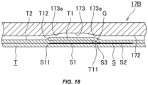
- the sealing tape (S) generally has a width which is approximately equal to "the width of the overlapping portion (T1) ⁇ 2". In an example, the width of the overlapping portion (T1) is 3.8 mm, and the width of the sealing tape (S) is 7.5 mm.
- the width of the SA-side portion (S1) of the sealing tape (S), which has been first attached to one surface of a web-like packaging material (W) in a tape attachment process and is located beside the overlapping portion (T1) is set to be approximately equal to the width of the LS-side portion (S2) of the sealing tape (S), which has been attached to the inner surface of the tubular packaging material (T) in a vertical sealing step and is located on the opposite side of the inner step (T11) of the overlapping portion (T1) from the overlapping portion (T1).
- the width of the SA-side portion (S1) of the sealing tape (S) and the width of the LS-side portion (S2) are each about 3.45 mm, which is one-half of a value obtained by subtracting the width of a portion (S3) facing an air gap (G) that lies adjacent to the inner step (T11) of the overlapping portion (T1), which is about 0.6 mm, from 7.5 mm (see FIG. 18 ).
- the first edge (S11) of the sealing tape (S) is disposed such that it approximately aligns with the outer step (T12) of the overlapping portion (T1) when viewed in the thickness direction of the tubular packaging material (T), as shown in FIG. 18 .
- the first edge (S11) (the left edge in the figures) of both edges of the sealing tape (S), which is located on the overlapping portion side (SA side) of the sealing tape (S) when viewed from the inner step (T11) of the overlapping portion (T1), is disposed at a position displaced from the outer step (T12) of the overlapping portion (T1) when viewed in the thickness direction of the tubular packaging material (T), as shown in FIGS. 6 through 8 .
- Such a position of the sealing tape (S) can be ensured by changing and adjusting the width of the SA-side portion (S1) of the sealing tape (S) which is attached to one end of one surface of the web-like packaging material (W) in a tape attachment step performed by a tape attachment device (13).
- the tape attachment device (13) is configured to be movable in a direction perpendicular to the sealing tape (S) feed direction so as to adjust the lateral position of the sealing tape (S), and therefore can arbitrarily change and adjust the relative position in the width direction between the sealing tape (S) and the tubular packaging material (T) in the tape attachment step.
- the first edge (S11) of the sealing tape (S) is disposed at a position which is displaced by a distance (D1) of not less than 0.5 mm, preferably not less than 1 mm from the outer step (T12) of the overlapping portion (T1) in a direction away from the inner step (T11) of the overlapping portion (T1).
- the sealing tape (S), like the conventional one, has a width which is approximately twice the width of the overlapping portion (T1).
- the poor sealing problems such as a failure in fusion-bonding of the SA-side first edge (S11) of the sealing tape (S) to the inner surface of the tubular packaging material (T) and the formation of a hollow space between the first edge (S11) and the inner surface of the tubular packaging material (T), can be effectively prevented even when the inner step (T11) and the outer step (T12) of the overlapping portion (T1) are positioned off the inclined surfaces (173a) of the recessed groove (absorption portion) (173) in the sealing surface (172) of the anvil (17B) upon lateral sealing.
- the first edge (S11) of the sealing tape (S) is disposed at a position which is displaced by a distance (D2) of 0.5 to 3 mm, preferably 1.5 to 3 mm from the outer step (T12) of the overlapping portion (T1) in a direction toward the inner step (T11) of the overlapping portion (T1).
- the sealing tape (S), like the conventional one, has a width which is approximately twice the width of the overlapping portion (T1).
- the sealing tape (S) has an increased width.
- the width of the overlapping portion (T1) is 4 mm
- the width of the sealing tape (S) is 11 mm which is approximately three times the width of the overlapping portion (T1).
- the first edge (S11) of the sealing tape (S) can be disposed at a position which is displaced by a sufficient distance (D1) (e.g., about 3 mm) from the outer step (T12) of the overlapping portion (T1) in a direction away from the inner step (T11) of the overlapping portion (T1) .
- D1 a sufficient distance
- the width of the sealing tape (S) is made narrower than normal.
- the first edge (S11) of the sealing tape (S) is generally disposed at a position which is displaced from the outer step (T12) of the overlapping portion (T1) in a direction toward the inner step (T11) of the overlapping portion (T1).
- the too small sealing area may result in a deterioration of sealing properties.
- the sealing tape (S) may have a larger width than that used in the above-described three modes which, as described above, is about two to three times the width of the overlapping portion (T1).
- the use of the sealing tape (S) having such a large width can achieve the following effect in addition to the above-described effect of preventing poor sealing:
- the sealing tape (S) can take the place of an inner tape for covering the inner surface of the opening.
- the sealing tape (S) can reach a crease of a container.
- sealing tape (S) having a width which is 1 to 10 times the width of the overlapping portion (T1).
- FIGS. 9 through 15 show details of a lateral sealing device of a filling packaging machine according to a second embodiment of the present invention.
- the lateral sealing device of the second embodiment is substantially the same as the lateral sealing device of the first embodiment shown in FIGS. 1 through 8 except for the following construction.
- the sealing surfaces (172) of the anvil (17B) each have two pressing protrusions (179), one is for pressing the first edge (S11) of the sealing tape (S) and a portion of the tubular packaging material (T) which overlaps the first edge (S11), and the other for pressing a second edge (S12) of the sealing tape (S) opposite from the first edge (S11) and a portion of the tubular packaging material (T) which overlaps the second edge (S12).
- the two pressing protrusions (179) are formed at the corresponding positions on each of the sealing surfaces (172) of the anvil (17B).
- two left and right pressing protrusions (179) are formed at positions below the horizontal groove (176) in the upper sealing surface (172) of the anvil (17B), and two left and right pressing protrusions (179) are formed at positions above the horizontal groove (176) in the lower sealing surface (172) of the anvil (17B).
- the lateral sealing device described above enables more secure sealing between the first and second edges (S11), (S12) of the sealing tape (S) and the inner surface of the tubular packaging material (T), and can therefore more effectively prevent the occurrence of leakage of contents due to poor sealing in such portions.
- pressing protrusions may be formed on the sealing surfaces (171) of the ultrasonic horn (17A).
- FIGS. 11 through 13 show in detail positions where the pressing protrusions (179) are formed in the three modes of the positional relationship between the overlapping portion (T1) of the tubular packaging material (T), the sealing tape (S), and the absorption portion (recessed groove) (173) in the sealing surface (172) of the anvil (17B) upon lateral sealing, shown in FIGS. 6 through 8 .
- the pressing protrusions (179) are formed at positions on both sides of and adjacent to the recessed groove (absorption portion) (173) in each of the upper and lower sealing surfaces (172), as shown in FIG. 11 .
- the pressing protrusions (179) are formed in the center of the bottom of the recessed groove (absorption portion) (173) in each of the upper and lower sealing surfaces (172), and at a position on the right of and at a considerable distance from the recessed groove (absorption portion) (173), as shown in FIG. 12 .
- the position of the pressing protrusion (179) corresponding to the first edge (S11) of the sealing tape (S) may be laterally displaced from the center of the bottom of the recessed groove (absorption portion) (173) depending on the attachment position of the sealing tape (S).
- the sealing tape (S) has a wide width, and therefore the first edge (S11) of the sealing tape (S) is disposed at a position which is displaced by a sufficient distance (D1) from the outer step (T12) of the overlapping portion (T1) in a direction away from the inner step (T11) of the overlapping portion (T1) (the mode illustrated in FIG. 8 ), the pressing protrusions (179) are formed at positions on both sides of and at a considerable distance from the recessed groove (absorption portion) (173) in each of the upper and lower sealing surfaces (172), as shown in FIG. 13 .
- the pressing protrusions are formed on the bottom of the recessed groove (absorption portion) (173) in each of the upper and lower sealing surfaces (172), and at a position on the right of and adjacent to the recessed groove (absorption portion) (173) .
- each pressing protrusion (179) has a ridge-like shape extending in the length direction of the sealing surface (172).
- Each pressing protrusion (179) preferably has the following dimensions: a length (L) of 1 to 5 mm; a thickness (TH) of 0.1 to 0.6 mm; and a protruding height (H) of 0.1 to 0.5 mm.
- each pressing protrusion (179) is less than 1 mm, there is a fear that the pressing protrusions (179) cannot securely press the both edges (S11), (S12) of the sealing tape (S) and those portions of the tubular packaging material (T) which overlap the edges (S11), (S12) when the position of the tubular packaging material (T) and the sealing tape (S) is displaced upon lateral sealing. If the length (L) exceeds 5 mm, on the other hand, there is a fear that the pressing protrusions (179) may also press portions other than the intended portions.
- each pressing protrusion (179) is less than 0.1 mm, it may quickly wear out. If the thickness (TH) exceeds 0.6 mm, on the other hand, the difference between the thickness (TH) and the width of the sealing surface (172) is small, which may result in a failure to fully achieve the above effect.
- each pressing protrusion (179) is less than 0.1 mm, there is a fear that the above effect cannot be securely achieved. If the protruding height (H) exceeds 0.5 mm, on the other hand, there is a fear of burning or cutting of the tubular packaging material (T) upon lateral sealing.
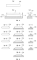
- Each pressing protrusion (179) may be rectangular in a front view, rectangular in a side view, and square in a cross-sectional view, as shown in FIG. 14 , or may have a shape which is an arbitrary combination of a front shape, a side shape and a cross-sectional shape as shown in FIG. 15 .
- each pressing protrusion (179) may be a generally rectangular shape with arcuate corners, a generally rectangular shape with chamfered corners, a race-track shape with semicircular short sides, or an elongated hexagonal shape with V-shaped short sides, as sequentially shown in FIGS. 15 (a-1) through 15(a-4).
- each pressing protrusion (179) may be a generally rectangular shape with arcuate front-end corners, a generally rectangular shape with chamfered front-end corners, an elongated isosceles trapezoidal shape, a generally elongated isosceles trapezoidal shape with arcuate short sides, or a domical shape, as sequentially shown in FIGS. 15 (b-1) through 15(b-5).
- each pressing protrusion (179) may be a generally square shape with arcuate front-end corners, a generally square shape with chamfered front-end corners, a triangular shape, or a semicircular shape, as sequentially shown in FIGS. 15 (c-1) through 15(c-4).
- the present invention can be advantageously applied in a filling packaging machine for filling and packaging contents, such as a fluid food or a beverage, into a container formed of a web-like packaging material composed of e.g. paper, in a content filling container, and in a manufacturing method for the content filling container.
Landscapes
- Engineering & Computer Science (AREA)
- Mechanical Engineering (AREA)
- Containers And Plastic Fillers For Packaging (AREA)
- Package Closures (AREA)
- Basic Packing Technique (AREA)
- Making Paper Articles (AREA)
- Auxiliary Devices For And Details Of Packaging Control (AREA)
Applications Claiming Priority (3)
| Application Number | Priority Date | Filing Date | Title |
|---|---|---|---|
| JP2018208549 | 2018-11-06 | ||
| JP2019015864 | 2019-01-31 | ||
| PCT/JP2019/037870 WO2020095562A1 (ja) | 2018-11-06 | 2019-09-26 | 充填包装機、内容物充填容器およびその製造方法 |
Publications (4)
| Publication Number | Publication Date |
|---|---|
| EP3851389A1 EP3851389A1 (en) | 2021-07-21 |
| EP3851389A4 EP3851389A4 (en) | 2022-06-29 |
| EP3851389C0 EP3851389C0 (en) | 2024-11-06 |
| EP3851389B1 true EP3851389B1 (en) | 2024-11-06 |
Family
ID=70610948
Family Applications (1)
| Application Number | Title | Priority Date | Filing Date |
|---|---|---|---|
| EP19881837.9A Active EP3851389B1 (en) | 2018-11-06 | 2019-09-26 | Filling packaging machine, content filling container, and manufacturing method therefor |
Country Status (12)
| Country | Link |
|---|---|
| US (1) | US20220002017A1 (https=) |
| EP (1) | EP3851389B1 (https=) |
| JP (1) | JP7525114B2 (https=) |
| KR (2) | KR20210087035A (https=) |
| CN (1) | CN112969642A (https=) |
| AU (1) | AU2019375269B2 (https=) |
| CA (1) | CA3118703A1 (https=) |
| MY (1) | MY208218A (https=) |
| PH (1) | PH12021550927A1 (https=) |
| SG (1) | SG11202103995XA (https=) |
| TW (1) | TWI813804B (https=) |
| WO (1) | WO2020095562A1 (https=) |
Families Citing this family (3)
| Publication number | Priority date | Publication date | Assignee | Title |
|---|---|---|---|---|
| PL4172046T3 (pl) * | 2020-09-28 | 2024-10-28 | Société des Produits Nestlé S.A. | Sposób wytwarzania opakowania z materiału nadającego się do recyklingu |
| WO2023198666A1 (en) * | 2022-04-12 | 2023-10-19 | Tetra Laval Holdings & Finance S.A. | A transversal sealing system and a method for transversally sealing a tube of packaging material |
| CN119233932A (zh) * | 2022-05-24 | 2024-12-31 | 雀巢产品有限公司 | 用于从可回收材料生产包装的方法 |
Family Cites Families (26)
| Publication number | Priority date | Publication date | Assignee | Title |
|---|---|---|---|---|
| US2406830A (en) * | 1944-06-09 | 1946-09-03 | Warren Featherbone Co | Method of sealing together two pieces of waterproof fabric, and the seam formed thereby |
| JP3004786U (ja) | 1994-05-31 | 1994-11-22 | 凸版印刷株式会社 | 液体容器の超音波シール装置 |
| TW383286B (en) * | 1996-07-08 | 2000-03-01 | Tetra Laval Holdings & Finance | Sealing apparatus and method for sealing |
| JP4316053B2 (ja) | 1999-07-05 | 2009-08-19 | 四国化工機株式会社 | 超音波シール装置 |
| JP4603122B2 (ja) * | 2000-02-23 | 2010-12-22 | 四国化工機株式会社 | 超音波シール装置 |
| KR100616288B1 (ko) * | 2001-12-25 | 2006-08-28 | 가부시키가이샤 프라스토 | 자립성 포장봉투, 포장체 및 원반로울 및 그들의 제조방법 |
| JP2003191917A (ja) * | 2001-12-26 | 2003-07-09 | Nihon Tetra Pak Kk | 充填機 |
| JP2003221016A (ja) * | 2002-01-25 | 2003-08-05 | Nihon Tetra Pak Kk | 横シール装置 |
| JP4931033B2 (ja) * | 2002-07-19 | 2012-05-16 | 日本テトラパック株式会社 | 積層材料、積層材料の製造方法および包装容器 |
| JP4592593B2 (ja) * | 2003-09-24 | 2010-12-01 | テトラ ラバル ホールディングス アンド ファイナンス エス エイ | 包装充填装置及び包材切断装置 |
| NZ578938A (en) | 2004-10-01 | 2010-05-28 | Orihiro Co Ltd | Heat sealing bar and a pillow packaging machine |
| JP4917802B2 (ja) | 2005-12-22 | 2012-04-18 | 日本テトラパック株式会社 | 包装容器製造装置及び包装容器製造方法 |
| JP2008094456A (ja) * | 2006-10-13 | 2008-04-24 | Ishida Co Ltd | 縦シール機構 |
| JP4863481B2 (ja) * | 2006-12-03 | 2012-01-25 | 日本テトラパック株式会社 | 包装充填装置 |
| JP2008143523A (ja) * | 2006-12-05 | 2008-06-26 | Nihon Tetra Pak Kk | 包装充填装置 |
| JP2008207830A (ja) * | 2007-02-26 | 2008-09-11 | Ishida Co Ltd | 薄肉包装袋およびその製造方法 |
| JP2009184724A (ja) * | 2008-02-10 | 2009-08-20 | Nihon Tetra Pak Kk | 包装充填装置 |
| JP2012131555A (ja) * | 2010-12-23 | 2012-07-12 | Nihon Tetra Pak Kk | 包装容器 |
| US8807834B2 (en) * | 2012-02-13 | 2014-08-19 | Cryovac, Inc. | Easy open and reclosable package with panel section with easy open sealant, and reclosure mechanism |
| JP6326220B2 (ja) * | 2013-11-27 | 2018-05-16 | 四国化工機株式会社 | 包装機械におけるチューブ状包材の位置ずれ監視装置 |
| JP2015117066A (ja) * | 2013-12-20 | 2015-06-25 | 凸版印刷株式会社 | 液体用紙容器の超音波シール装置 |
| JP6553890B2 (ja) * | 2015-02-20 | 2019-07-31 | 日本テトラパック株式会社 | 包装充填装置 |
| JP6822406B2 (ja) * | 2015-08-31 | 2021-01-27 | 凸版印刷株式会社 | 超音波シール方法 |
| CN108137181B (zh) * | 2015-10-02 | 2021-02-26 | 凸版印刷株式会社 | 砧座及超声波密封装置 |
| US11434028B2 (en) * | 2017-08-04 | 2022-09-06 | Tetra Laval Holdings & Finance S.A. | Method and an apparatus for applying a sealing strip to a web of packaging material |
| CN109383862B (zh) * | 2017-08-04 | 2021-07-13 | 利乐拉瓦尔集团及财务有限公司 | 用于横向密封包装材料管的砧座和具有砧座的密封钳 |
-
2019
- 2019-09-26 CN CN201980072430.5A patent/CN112969642A/zh active Pending
- 2019-09-26 SG SG11202103995XA patent/SG11202103995XA/en unknown
- 2019-09-26 WO PCT/JP2019/037870 patent/WO2020095562A1/ja not_active Ceased
- 2019-09-26 JP JP2020556674A patent/JP7525114B2/ja active Active
- 2019-09-26 MY MYPI2021002137A patent/MY208218A/en unknown
- 2019-09-26 KR KR1020217013435A patent/KR20210087035A/ko not_active Ceased
- 2019-09-26 CA CA3118703A patent/CA3118703A1/en active Pending
- 2019-09-26 PH PH1/2021/550927A patent/PH12021550927A1/en unknown
- 2019-09-26 KR KR1020247022702A patent/KR20240112974A/ko active Pending
- 2019-09-26 AU AU2019375269A patent/AU2019375269B2/en active Active
- 2019-09-26 US US17/289,458 patent/US20220002017A1/en not_active Abandoned
- 2019-09-26 EP EP19881837.9A patent/EP3851389B1/en active Active
- 2019-10-28 TW TW108138776A patent/TWI813804B/zh active
Also Published As
| Publication number | Publication date |
|---|---|
| SG11202103995XA (en) | 2021-05-28 |
| WO2020095562A1 (ja) | 2020-05-14 |
| AU2019375269B2 (en) | 2025-03-27 |
| KR20210087035A (ko) | 2021-07-09 |
| CN112969642A (zh) | 2021-06-15 |
| EP3851389A4 (en) | 2022-06-29 |
| EP3851389C0 (en) | 2024-11-06 |
| EP3851389A1 (en) | 2021-07-21 |
| JP7525114B2 (ja) | 2024-07-30 |
| MY208218A (en) | 2025-04-24 |
| TW202028062A (zh) | 2020-08-01 |
| US20220002017A1 (en) | 2022-01-06 |
| KR20240112974A (ko) | 2024-07-19 |
| CA3118703A1 (en) | 2020-05-14 |
| JPWO2020095562A1 (ja) | 2021-12-23 |
| AU2019375269A1 (en) | 2021-05-20 |
| TWI813804B (zh) | 2023-09-01 |
| PH12021550927A1 (en) | 2022-05-02 |
Similar Documents
| Publication | Publication Date | Title |
|---|---|---|
| EP3851389B1 (en) | Filling packaging machine, content filling container, and manufacturing method therefor | |
| JP5241985B2 (ja) | 包装容器、及び包装容器をシート包装材料から製造する方法 | |
| EP0730946B1 (en) | Heat-sealing device for liquid-filled tube | |
| US5155980A (en) | Forming device in packaging machines | |
| RU2392202C2 (ru) | Устройство и способ поперечного запечатывания | |
| EP2445821B1 (en) | Strip splicing | |
| EP3693282B1 (en) | Ultrasonic sealing anvil and ultrasonic sealing apparatus | |
| ITTO20001150A1 (it) | Confezione sigillata di tipo perfezionato per prodotti alimentari versabili. | |
| KR100944612B1 (ko) | 식품 포장용기를 제조하기 위한 시트 재료 및 이러한 시트재료로 제조되는 포장용기 | |
| UA78675C2 (uk) | Пластмасовий пакет "майка" (варіанти) та спосіб його виробництва | |
| JPH02242763A (ja) | パッケージ及びパッケージの製造方法 | |
| US20150016757A1 (en) | Butt seamed package bag and method for using same | |
| EP3581509B1 (en) | Package comprising an opening device | |
| JP3329860B2 (ja) | ヒートシールロール | |
| JP7618243B2 (ja) | 充填包装機およびこれに用いられる横シール装置 | |
| JP5019538B2 (ja) | 包装袋及び縦形製袋充填包装機 | |
| HK40050144A (en) | Filling packaging machine, content filling container, and manufacturing method therefor | |
| JPH04267750A (ja) | 包装袋用積層フィルム | |
| JP6962744B2 (ja) | 内容物の充填包装方法及び縦型充填包装機 | |
| JP2951747B2 (ja) | 易開封性包装袋 | |
| JP3930305B2 (ja) | 充填包装装置及び方法 | |
| CN121175176A (zh) | 超声波密封系统及其砧座 | |
| US20220315307A1 (en) | Packaging bag, method for manufacturing packaging bag, and pressing member | |
| JP2025140620A (ja) | 充填包装機用超音波シール装置 | |
| CN121038945A (zh) | 超声波密封系统及其砧座 |
Legal Events
| Date | Code | Title | Description |
|---|---|---|---|
| STAA | Information on the status of an ep patent application or granted ep patent |
Free format text: STATUS: THE INTERNATIONAL PUBLICATION HAS BEEN MADE |
|
| PUAI | Public reference made under article 153(3) epc to a published international application that has entered the european phase |
Free format text: ORIGINAL CODE: 0009012 |
|
| STAA | Information on the status of an ep patent application or granted ep patent |
Free format text: STATUS: REQUEST FOR EXAMINATION WAS MADE |
|
| 17P | Request for examination filed |
Effective date: 20210413 |
|
| AK | Designated contracting states |
Kind code of ref document: A1 Designated state(s): AL AT BE BG CH CY CZ DE DK EE ES FI FR GB GR HR HU IE IS IT LI LT LU LV MC MK MT NL NO PL PT RO RS SE SI SK SM TR |
|
| DAV | Request for validation of the european patent (deleted) | ||
| DAX | Request for extension of the european patent (deleted) | ||
| A4 | Supplementary search report drawn up and despatched |
Effective date: 20220527 |
|
| RIC1 | Information provided on ipc code assigned before grant |
Ipc: B65B 9/20 20120101AFI20220520BHEP |
|
| REG | Reference to a national code |
Ref country code: DE Ref legal event code: R079 Free format text: PREVIOUS MAIN CLASS: B65B0009200000 Ipc: B65B0051300000 Ref country code: DE Ref legal event code: R079 Ref document number: 602019061715 Country of ref document: DE Free format text: PREVIOUS MAIN CLASS: B65B0009200000 Ipc: B65B0051300000 |
|
| RIC1 | Information provided on ipc code assigned before grant |
Ipc: B29C 65/48 20060101ALI20240404BHEP Ipc: B65B 51/04 20060101ALI20240404BHEP Ipc: B65B 9/20 20120101ALI20240404BHEP Ipc: B29C 65/50 20060101ALI20240404BHEP Ipc: B29C 65/74 20060101ALI20240404BHEP Ipc: B29C 65/00 20060101ALI20240404BHEP Ipc: B29C 65/08 20060101ALI20240404BHEP Ipc: B65B 51/30 20060101AFI20240404BHEP |
|
| GRAP | Despatch of communication of intention to grant a patent |
Free format text: ORIGINAL CODE: EPIDOSNIGR1 |
|
| STAA | Information on the status of an ep patent application or granted ep patent |
Free format text: STATUS: GRANT OF PATENT IS INTENDED |
|
| INTG | Intention to grant announced |
Effective date: 20240527 |
|
| GRAS | Grant fee paid |
Free format text: ORIGINAL CODE: EPIDOSNIGR3 |
|
| GRAA | (expected) grant |
Free format text: ORIGINAL CODE: 0009210 |
|
| STAA | Information on the status of an ep patent application or granted ep patent |
Free format text: STATUS: THE PATENT HAS BEEN GRANTED |
|
| AK | Designated contracting states |
Kind code of ref document: B1 Designated state(s): AL AT BE BG CH CY CZ DE DK EE ES FI FR GB GR HR HU IE IS IT LI LT LU LV MC MK MT NL NO PL PT RO RS SE SI SK SM TR |
|
| REG | Reference to a national code |
Ref country code: GB Ref legal event code: FG4D |
|
| REG | Reference to a national code |
Ref country code: CH Ref legal event code: EP |
|
| REG | Reference to a national code |
Ref country code: DE Ref legal event code: R096 Ref document number: 602019061715 Country of ref document: DE |
|
| REG | Reference to a national code |
Ref country code: IE Ref legal event code: FG4D |
|
| U01 | Request for unitary effect filed |
Effective date: 20241126 |
|
| U07 | Unitary effect registered |
Designated state(s): AT BE BG DE DK EE FI FR IT LT LU LV MT NL PT RO SE SI Effective date: 20241202 |
|
| PG25 | Lapsed in a contracting state [announced via postgrant information from national office to epo] |
Ref country code: HR Free format text: LAPSE BECAUSE OF FAILURE TO SUBMIT A TRANSLATION OF THE DESCRIPTION OR TO PAY THE FEE WITHIN THE PRESCRIBED TIME-LIMIT Effective date: 20241106 Ref country code: IS Free format text: LAPSE BECAUSE OF FAILURE TO SUBMIT A TRANSLATION OF THE DESCRIPTION OR TO PAY THE FEE WITHIN THE PRESCRIBED TIME-LIMIT Effective date: 20250306 |
|
| PG25 | Lapsed in a contracting state [announced via postgrant information from national office to epo] |
Ref country code: ES Free format text: LAPSE BECAUSE OF FAILURE TO SUBMIT A TRANSLATION OF THE DESCRIPTION OR TO PAY THE FEE WITHIN THE PRESCRIBED TIME-LIMIT Effective date: 20241106 |
|
| PG25 | Lapsed in a contracting state [announced via postgrant information from national office to epo] |
Ref country code: NO Free format text: LAPSE BECAUSE OF FAILURE TO SUBMIT A TRANSLATION OF THE DESCRIPTION OR TO PAY THE FEE WITHIN THE PRESCRIBED TIME-LIMIT Effective date: 20250206 |
|
| PG25 | Lapsed in a contracting state [announced via postgrant information from national office to epo] |
Ref country code: GR Free format text: LAPSE BECAUSE OF FAILURE TO SUBMIT A TRANSLATION OF THE DESCRIPTION OR TO PAY THE FEE WITHIN THE PRESCRIBED TIME-LIMIT Effective date: 20250207 |
|
| PG25 | Lapsed in a contracting state [announced via postgrant information from national office to epo] |
Ref country code: PL Free format text: LAPSE BECAUSE OF FAILURE TO SUBMIT A TRANSLATION OF THE DESCRIPTION OR TO PAY THE FEE WITHIN THE PRESCRIBED TIME-LIMIT Effective date: 20241106 |
|
| PG25 | Lapsed in a contracting state [announced via postgrant information from national office to epo] |
Ref country code: RS Free format text: LAPSE BECAUSE OF FAILURE TO SUBMIT A TRANSLATION OF THE DESCRIPTION OR TO PAY THE FEE WITHIN THE PRESCRIBED TIME-LIMIT Effective date: 20250206 |
|
| PG25 | Lapsed in a contracting state [announced via postgrant information from national office to epo] |
Ref country code: SM Free format text: LAPSE BECAUSE OF FAILURE TO SUBMIT A TRANSLATION OF THE DESCRIPTION OR TO PAY THE FEE WITHIN THE PRESCRIBED TIME-LIMIT Effective date: 20241106 |
|
| PG25 | Lapsed in a contracting state [announced via postgrant information from national office to epo] |
Ref country code: SK Free format text: LAPSE BECAUSE OF FAILURE TO SUBMIT A TRANSLATION OF THE DESCRIPTION OR TO PAY THE FEE WITHIN THE PRESCRIBED TIME-LIMIT Effective date: 20241106 |
|
| PG25 | Lapsed in a contracting state [announced via postgrant information from national office to epo] |
Ref country code: CZ Free format text: LAPSE BECAUSE OF FAILURE TO SUBMIT A TRANSLATION OF THE DESCRIPTION OR TO PAY THE FEE WITHIN THE PRESCRIBED TIME-LIMIT Effective date: 20241106 |
|
| PLBE | No opposition filed within time limit |
Free format text: ORIGINAL CODE: 0009261 |
|
| STAA | Information on the status of an ep patent application or granted ep patent |
Free format text: STATUS: NO OPPOSITION FILED WITHIN TIME LIMIT |
|
| 26N | No opposition filed |
Effective date: 20250807 |
|
| U20 | Renewal fee for the european patent with unitary effect paid |
Year of fee payment: 7 Effective date: 20250926 |