EP3848247B1 - Dispositif de commande d'affichage pour rétroviseur électronique et système de rétroviseur électronique le comprenant - Google Patents
Dispositif de commande d'affichage pour rétroviseur électronique et système de rétroviseur électronique le comprenant Download PDFInfo
- Publication number
- EP3848247B1 EP3848247B1 EP19857209.1A EP19857209A EP3848247B1 EP 3848247 B1 EP3848247 B1 EP 3848247B1 EP 19857209 A EP19857209 A EP 19857209A EP 3848247 B1 EP3848247 B1 EP 3848247B1
- Authority
- EP
- European Patent Office
- Prior art keywords
- display
- mode
- modes
- electronic mirror
- control device
- Prior art date
- Legal status (The legal status is an assumption and is not a legal conclusion. Google has not performed a legal analysis and makes no representation as to the accuracy of the status listed.)
- Active
Links
- 238000012423 maintenance Methods 0.000 claims description 83
- 230000003287 optical effect Effects 0.000 claims description 27
- 238000003860 storage Methods 0.000 claims description 22
- 238000012937 correction Methods 0.000 claims description 5
- 238000003384 imaging method Methods 0.000 claims description 4
- 238000003825 pressing Methods 0.000 claims description 2
- 238000000034 method Methods 0.000 description 33
- 230000008569 process Effects 0.000 description 28
- 238000013461 design Methods 0.000 description 16
- 238000001514 detection method Methods 0.000 description 11
- 230000007704 transition Effects 0.000 description 11
- 238000010586 diagram Methods 0.000 description 6
- 238000000275 quality assurance Methods 0.000 description 6
- 230000001960 triggered effect Effects 0.000 description 5
- 230000007246 mechanism Effects 0.000 description 4
- 230000007935 neutral effect Effects 0.000 description 3
- 230000000007 visual effect Effects 0.000 description 3
- 230000008859 change Effects 0.000 description 2
- 238000004891 communication Methods 0.000 description 2
- 238000005520 cutting process Methods 0.000 description 2
- 230000006870 function Effects 0.000 description 2
- 239000011521 glass Substances 0.000 description 2
- 238000009434 installation Methods 0.000 description 2
- 238000004519 manufacturing process Methods 0.000 description 2
- 238000012986 modification Methods 0.000 description 2
- 230000004048 modification Effects 0.000 description 2
- 238000011161 development Methods 0.000 description 1
- 230000018109 developmental process Effects 0.000 description 1
- 230000000694 effects Effects 0.000 description 1
- 239000004973 liquid crystal related substance Substances 0.000 description 1
- 238000012545 processing Methods 0.000 description 1
Images


Classifications
-
- B—PERFORMING OPERATIONS; TRANSPORTING
- B60—VEHICLES IN GENERAL
- B60R—VEHICLES, VEHICLE FITTINGS, OR VEHICLE PARTS, NOT OTHERWISE PROVIDED FOR
- B60R1/00—Optical viewing arrangements; Real-time viewing arrangements for drivers or passengers using optical image capturing systems, e.g. cameras or video systems specially adapted for use in or on vehicles
- B60R1/12—Mirror assemblies combined with other articles, e.g. clocks
- B60R1/1207—Mirror assemblies combined with other articles, e.g. clocks with lamps; with turn indicators
-
- B—PERFORMING OPERATIONS; TRANSPORTING
- B60—VEHICLES IN GENERAL
- B60R—VEHICLES, VEHICLE FITTINGS, OR VEHICLE PARTS, NOT OTHERWISE PROVIDED FOR
- B60R1/00—Optical viewing arrangements; Real-time viewing arrangements for drivers or passengers using optical image capturing systems, e.g. cameras or video systems specially adapted for use in or on vehicles
- B60R1/02—Rear-view mirror arrangements
- B60R1/08—Rear-view mirror arrangements involving special optical features, e.g. avoiding blind spots, e.g. convex mirrors; Side-by-side associations of rear-view and other mirrors
-
- B—PERFORMING OPERATIONS; TRANSPORTING
- B60—VEHICLES IN GENERAL
- B60R—VEHICLES, VEHICLE FITTINGS, OR VEHICLE PARTS, NOT OTHERWISE PROVIDED FOR
- B60R1/00—Optical viewing arrangements; Real-time viewing arrangements for drivers or passengers using optical image capturing systems, e.g. cameras or video systems specially adapted for use in or on vehicles
- B60R1/20—Real-time viewing arrangements for drivers or passengers using optical image capturing systems, e.g. cameras or video systems specially adapted for use in or on vehicles
- B60R1/22—Real-time viewing arrangements for drivers or passengers using optical image capturing systems, e.g. cameras or video systems specially adapted for use in or on vehicles for viewing an area outside the vehicle, e.g. the exterior of the vehicle
- B60R1/23—Real-time viewing arrangements for drivers or passengers using optical image capturing systems, e.g. cameras or video systems specially adapted for use in or on vehicles for viewing an area outside the vehicle, e.g. the exterior of the vehicle with a predetermined field of view
- B60R1/26—Real-time viewing arrangements for drivers or passengers using optical image capturing systems, e.g. cameras or video systems specially adapted for use in or on vehicles for viewing an area outside the vehicle, e.g. the exterior of the vehicle with a predetermined field of view to the rear of the vehicle
-
- B—PERFORMING OPERATIONS; TRANSPORTING
- B60—VEHICLES IN GENERAL
- B60R—VEHICLES, VEHICLE FITTINGS, OR VEHICLE PARTS, NOT OTHERWISE PROVIDED FOR
- B60R1/00—Optical viewing arrangements; Real-time viewing arrangements for drivers or passengers using optical image capturing systems, e.g. cameras or video systems specially adapted for use in or on vehicles
- B60R1/20—Real-time viewing arrangements for drivers or passengers using optical image capturing systems, e.g. cameras or video systems specially adapted for use in or on vehicles
- B60R1/22—Real-time viewing arrangements for drivers or passengers using optical image capturing systems, e.g. cameras or video systems specially adapted for use in or on vehicles for viewing an area outside the vehicle, e.g. the exterior of the vehicle
- B60R1/28—Real-time viewing arrangements for drivers or passengers using optical image capturing systems, e.g. cameras or video systems specially adapted for use in or on vehicles for viewing an area outside the vehicle, e.g. the exterior of the vehicle with an adjustable field of view
-
- B—PERFORMING OPERATIONS; TRANSPORTING
- B60—VEHICLES IN GENERAL
- B60R—VEHICLES, VEHICLE FITTINGS, OR VEHICLE PARTS, NOT OTHERWISE PROVIDED FOR
- B60R1/00—Optical viewing arrangements; Real-time viewing arrangements for drivers or passengers using optical image capturing systems, e.g. cameras or video systems specially adapted for use in or on vehicles
- B60R1/12—Mirror assemblies combined with other articles, e.g. clocks
- B60R2001/1253—Mirror assemblies combined with other articles, e.g. clocks with cameras, video cameras or video screens
-
- B—PERFORMING OPERATIONS; TRANSPORTING
- B60—VEHICLES IN GENERAL
- B60R—VEHICLES, VEHICLE FITTINGS, OR VEHICLE PARTS, NOT OTHERWISE PROVIDED FOR
- B60R2300/00—Details of viewing arrangements using cameras and displays, specially adapted for use in a vehicle
- B60R2300/30—Details of viewing arrangements using cameras and displays, specially adapted for use in a vehicle characterised by the type of image processing
- B60R2300/306—Details of viewing arrangements using cameras and displays, specially adapted for use in a vehicle characterised by the type of image processing using a re-scaling of images
-
- B—PERFORMING OPERATIONS; TRANSPORTING
- B60—VEHICLES IN GENERAL
- B60R—VEHICLES, VEHICLE FITTINGS, OR VEHICLE PARTS, NOT OTHERWISE PROVIDED FOR
- B60R2300/00—Details of viewing arrangements using cameras and displays, specially adapted for use in a vehicle
- B60R2300/30—Details of viewing arrangements using cameras and displays, specially adapted for use in a vehicle characterised by the type of image processing
- B60R2300/307—Details of viewing arrangements using cameras and displays, specially adapted for use in a vehicle characterised by the type of image processing virtually distinguishing relevant parts of a scene from the background of the scene
-
- B—PERFORMING OPERATIONS; TRANSPORTING
- B60—VEHICLES IN GENERAL
- B60R—VEHICLES, VEHICLE FITTINGS, OR VEHICLE PARTS, NOT OTHERWISE PROVIDED FOR
- B60R2300/00—Details of viewing arrangements using cameras and displays, specially adapted for use in a vehicle
- B60R2300/60—Details of viewing arrangements using cameras and displays, specially adapted for use in a vehicle characterised by monitoring and displaying vehicle exterior scenes from a transformed perspective
- B60R2300/602—Details of viewing arrangements using cameras and displays, specially adapted for use in a vehicle characterised by monitoring and displaying vehicle exterior scenes from a transformed perspective with an adjustable viewpoint
- B60R2300/605—Details of viewing arrangements using cameras and displays, specially adapted for use in a vehicle characterised by monitoring and displaying vehicle exterior scenes from a transformed perspective with an adjustable viewpoint the adjustment being automatic
-
- B—PERFORMING OPERATIONS; TRANSPORTING
- B60—VEHICLES IN GENERAL
- B60R—VEHICLES, VEHICLE FITTINGS, OR VEHICLE PARTS, NOT OTHERWISE PROVIDED FOR
- B60R2300/00—Details of viewing arrangements using cameras and displays, specially adapted for use in a vehicle
- B60R2300/70—Details of viewing arrangements using cameras and displays, specially adapted for use in a vehicle characterised by an event-triggered choice to display a specific image among a selection of captured images
-
- B—PERFORMING OPERATIONS; TRANSPORTING
- B60—VEHICLES IN GENERAL
- B60R—VEHICLES, VEHICLE FITTINGS, OR VEHICLE PARTS, NOT OTHERWISE PROVIDED FOR
- B60R2300/00—Details of viewing arrangements using cameras and displays, specially adapted for use in a vehicle
- B60R2300/80—Details of viewing arrangements using cameras and displays, specially adapted for use in a vehicle characterised by the intended use of the viewing arrangement
- B60R2300/802—Details of viewing arrangements using cameras and displays, specially adapted for use in a vehicle characterised by the intended use of the viewing arrangement for monitoring and displaying vehicle exterior blind spot views
-
- B—PERFORMING OPERATIONS; TRANSPORTING
- B60—VEHICLES IN GENERAL
- B60R—VEHICLES, VEHICLE FITTINGS, OR VEHICLE PARTS, NOT OTHERWISE PROVIDED FOR
- B60R2300/00—Details of viewing arrangements using cameras and displays, specially adapted for use in a vehicle
- B60R2300/80—Details of viewing arrangements using cameras and displays, specially adapted for use in a vehicle characterised by the intended use of the viewing arrangement
- B60R2300/8046—Details of viewing arrangements using cameras and displays, specially adapted for use in a vehicle characterised by the intended use of the viewing arrangement for replacing a rear-view mirror system
-
- B—PERFORMING OPERATIONS; TRANSPORTING
- B60—VEHICLES IN GENERAL
- B60R—VEHICLES, VEHICLE FITTINGS, OR VEHICLE PARTS, NOT OTHERWISE PROVIDED FOR
- B60R2300/00—Details of viewing arrangements using cameras and displays, specially adapted for use in a vehicle
- B60R2300/80—Details of viewing arrangements using cameras and displays, specially adapted for use in a vehicle characterised by the intended use of the viewing arrangement
- B60R2300/8066—Details of viewing arrangements using cameras and displays, specially adapted for use in a vehicle characterised by the intended use of the viewing arrangement for monitoring rearward traffic
Definitions
- the present disclosure relates to a display control device for an electronic mirror that controls the display of an electronic mirror that displays video images of around a vehicle, and an electronic mirror system including the display control device.
- a display control device for an electronic mirror has been proposed in which a camera captures video images of an area surrounding a vehicle, and switches the video image range between displaying the video images as video images within a range equivalent to an optical mirror, displaying video images in a wider range, or the like.
- the display range of an image on a display device of an electronic mirror is adjusted by changing a cut-out angle of view according to the steering angle.
- EP 2 547 104 A1 discloses an image control apparatus designed to allow a driver to easily check the situation of a passengers getting on/off a vehicle through an opening operation of a door of the vehicle, wherein the apparatus includes a camera which captures an image of the vicinity of the vehicle door, a monitor capable of displaying the image captured by the camera and a door opening detection sensor which detects an open state of the vehicle door. The monitor displays the image captured by the camera when the door opening detection sensor detects an open state of the door.
- the display control device disclosed in this document corresponds to the preamble of claim 1.
- WO 2015 / 098 156 A1 relates to a visual field support device, a visual field support method and a visual field support program, whereas FR 2 038 873 A1 teaches an electronic vehicle mirror system that displays images of a right rear area and a left rear area of a vehicle in a display means.
- the selection of the display mode by the electronic mirror is generally performed by diverting the buttons of an existing optical mirror, so it is necessary to realize the state transition according to the situation with a small number of switches.
- An object according to the present disclosure is to provide a display control device for an electronic mirror capable of reducing design man-hours and improving quality assurance, and an electronic mirror system comprising such a display control device.
- each display mode when the display control device performs a display on the electronic mirror is prioritized in a hierarchical structure, and the mode is set according to the priority. Therefore, in a case where there are display modes that satisfy the mode setting conditions, the display mode having the highest priority may be selected from those display modes and that mode may be set.
- the electronic mirror system mounted in a vehicle according to a first embodiment and the display control device provided therein will be described.
- the electronic mirror system is a system including an electronic mirror and various configurations for performing control of the display by the electronic mirror, and the display control device constitutes an electronic control device for controlling the display thereof.
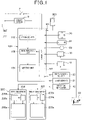
- the configuration of the electronic mirror system including the display control device 100, the electronic mirror 200, and the like will be described with reference to FIGS. 1 and 2 .
- the electronic mirror system includes cameras 10, 11, various switches 20 to 23, a shift position sensor 30, a door sensor 31, a direction indicator 40, and the like. Moreover, in the electronic mirror system, it is possible to set the display mode by using an external terminal 300.
- the display control device 100 controls the display on the electronic mirror 200 and causes an image to be displayed in a specified display mode, and the configuration includes a well-known microcomputer equipped with a CPU, ROM, RAM, I / O, timer, and the like.
- the display control device 100 is driven based on the power supplied from a power supply 1 that uses a constant voltage source such as a battery or a +B power supply in the vehicle as the power supply 1. Then, the display control device 100 performs control of the display of the electronic mirror 200 by executing various processes according to a program stored in a memory corresponding to a non-transitional substantive recording medium such as a ROM, a RAM, or the like.
- the display control device 100 When an ignition switch (hereinafter referred to as IG) 2 is turned ON, the display control device 100 is driven by receiving the power supplied from the power supply 1; however, here, even when the IG 2 is turned OFF, the display control device 100 is designed to be driven for a specified period of time, 7 minutes for example. In the case of the present embodiment, the display control device 100 is able to receive power supplied from the power supply 1 and also via a delay circuit 3. Therefore, the display control device 100 continues to be driven for a specified period by receiving the power supplied via the delay circuit 3 even after the IG 2 is turned OFF, and power supplied from the power supply 1 may not be received directly.
- IG ignition switch
- the display control device 100 is configured to include an input unit 101, a storage unit 102, a determination unit 103, a setting unit 104, and the like.
- the input unit 101 inputs various input signals used for selecting the display mode of the electronic mirror 200.
- the input unit 101 inputs an ON/OFF signal of the IG 2 and a signal indicating an operating state of various switches 20 to 22 for controlling the electronic mirror 200 as input signals.
- the input unit 101 also inputs detection signals of a shift position sensor 30 and the door sensor 31, and a signal indicating the operating state of the direction indicator 40 as input signals.
- the input unit 101 has an input terminal 50, and is such that input signals indicating instruction commands from an external terminal 300 such as a tester or the like are also inputted.
- the storage unit 102 is configured by a memory such as a ROM or the like, and as will be described later, stores mode setting conditions and mode release conditions of various display modes, and data having a hierarchical structure by giving priority to each display mode.
- the determination unit 103 is a unit that determines whether the mode setting conditions or the mode release conditions are satisfied for each of the plurality of display modes based on the input signal inputted by the input unit 101. Moreover, of the display modes among the plurality of display modes that satisfy the mode setting conditions, a setting unit 104 sets the display mode having the highest priority as the display mode to be displayed on the electronic mirror 200.
- the display control device 100 by each of the functional units, performs setting of the display mode according to the situation, and sends the image data after image processing has been performed according to the set display mode to the electronic mirror 200.
- the electronic mirror 200 performs an image display according to the display mode. Note that details of the display mode settings, the priority, and the like when the electronic mirror 200 performs a display will be described later.
- the cameras 10, 11 capture video images to be projected on the electronic mirror 200, and capture the state around the vehicle, which in this case is the state behind the vehicle.
- the right rear side camera 10 captures images of a specified angular range in the right rear of the vehicle
- the left rear side camera 11 captures images of a specified angular range in the left rear of the vehicle.
- each camera 10, 11 is mounted at a position adjacent to the bottom portion of a pillar A of a front door, or in other words, as illustrated in FIG. 2 , is installed at an installation position of a conventional side mirror so as to face the rear of the vehicle.
- the electronic mirror 200 has a configuration including a right-side mirror 201 that displays an image corresponding to the right rear of the vehicle, and a left-side mirror 202 that displays an image corresponding to the left rear of the vehicle.
- the video images captured by the right rear side camera 10 are used for the display on the right-side mirror 201
- the video images captured by the left rear side camera 11 are used for the display on the left-side mirror 202.
- the cameras 10, 11 are each configured, for example, by a CCD (Charge Coupled Device) camera; however, any camera may be used as long as the camera is able to capture images, and the imaging range of the cameras 10, 11 is also arbitrary. However, it is presumed that the cameras 10, 11 are able to capture a wider range than the display range of the electronic mirror 200. More specifically, as the display form of the electronic mirror 200, there is a form of displaying video images with a display angle equivalent to that of an optical mirror (hereinafter referred to as an optical angle display), a form of displaying video images with a wider display angle (hereinafter referred to as a wide-angle display), and the like.
- an optical angle display a form of displaying video images with a wider display angle
- a wide-angle display a wide-angle display
- the angular range of the display angle is 20 to 30 degrees
- the angular range of the display angle is larger than 30 degrees.
- the optical angle display and the wide-angle display are performed by partially cutting out the image data captured by the cameras 10, 11. Therefore, in order that a wide-angle display having a wider angular range is possible, the image range W by the cameras 10, 11 illustrated in FIG. 2 is set to be a wider range than the range used for the wide-angle display.
- switches 20 to 23 are used for operating the electronic mirror 200.
- the various switches 20 to 23 include a cross switch 20, an LR switch 21, an ON/MENU switch 22, and an electric storage switch 23. Of these switches 20 to 23, for switches 20 to 22 other than the electric storage switch 23, a signal indicating an operating state is inputted to the display control device 100.
- the cross switch 20 is a switch for performing position adjustment of the display center of the display image of the electronic mirror 200 in the same manner as adjusting the orientation of a side mirror composed of an optical mirror. As illustrated in FIG. 1 , the cross switch 20 has arrow displays directed to each of the up, down, left, and right directions, and a signal corresponding to the pressed direction is inputted to the display control device 100.
- a state in which a display is performed by the electronic mirror 200 so that the center of the video image screen captured by the cameras 10, 11 coincides with the center of the electronic mirror 200 is taken to be a reference state.
- the cross switch 20 When the cross switch 20 is operated, the position of the center of the display by the electronic mirror 200 is shifted in the operation direction with respect to the display in the reference state.
- the display image on the electronic mirror 200 is adjusted to be the image at a position above the position before the cross switch 20 is switched.
- a specified range centered on a position in the center of the video image screen captured by the cameras 10, 11 is projected on the electronic mirror 200.
- the up arrow position of the cross switch 20 when the up arrow position of the cross switch 20 is pressed, a specified range centered on a position above the center position of the image screen is projected on the electronic mirror 200.
- the cross switch 20 is also used for an operation or the like for performing correction of positional deviation of the cameras 10, 11 in a case where the display is performed in a maintenance mode described later. Furthermore, the cross switch 20 is also used for an operation of selecting an arbitrary MENU from a plurality of MENU contents displayed on a MENU display when the ON/MENU switch 22 is pressed to display the MENU.
- the LR switch 21 is a switch for selecting which of the right-side mirror 201 and the left-side mirror 202 for performing positional adjustment of the display center by the cross switch 20.
- the LR switch 21 is configured by a seesaw switch, and is capable of switching between an L position and an R position for selecting either "L" or "R” and a neutral position in which neither is selected. Then, a signal corresponding to the operating state of the LR switch 21 is inputted to the display control device 100.
- the LR switch 21 is operated before the operation of the cross switch 20, and by operating the cross switch 20 in a state in which the switch is tilted to the desired direction "L" or "R" to be selected, positional adjustment of the display center may be performed for the electronic mirror 200 on the selected side.
- the ON/MENU switch 22 corresponds to a setting switch, and is a switch for turning ON/OFF a special display by the electronic mirror 200 and for performing a display of a menu when performing the special display.
- the special display means a display in a mode other than the optical angle display such as a wide-angle display by the electronic mirror 200, or in other words, a display that cannot be performed by an optical mirror but may be performed by the electronic mirror 200.
- a menu is displayed on the electronic mirror 200. Based on this, by operating the cross switch 20, arbitrary contents are selected from among the plurality of contents displayed in the menu, and the electronic mirror 200 may be set to perform a display according to the selected contents. While the menu is displayed, there is an ON/OFF setting menu for setting whether to perform the special display by the electronic mirror 200, and based on this, the special display may also be set to be ON or OFF.
- the electric storage switch 23 is a switch for storing the cameras 10, 11.
- the cameras 10, 11 may be switched between the deployed state and the stored state by a storage mechanism such as an electric motor or the like (not illustrated), and the electric storage switch 23 may be used as a switch for driving the storage mechanism.
- the electric storage switch 23 is configured by a push switch, and in a state of not being pressed, controls the cameras 10, 11 so as to be in the deployed state, and in a state of being pressed, controls the cameras 10, 11 so as to be in the stored state.
- the signal from the electric storage switch 23 may be supplied to the display control device 100, and the display control device 100 may control the deployment and storage of the cameras 10, 11; however, here, the storage mechanism is able to be directly driven by the operation of the electric storage switch 23.
- the switches other than the ON/MENU switch 22 are existing switches that are used for adjusting the side mirrors configured of optical mirrors. It is desired that the electronic mirror 200 allows various display modes to be set according to the situation; however, it is difficult to newly increase the number of switches just for that purpose. For this reason, setting the display mode may be performed by using existing switches, and the cross switch 20, LR switch 21, and ON/MENU switch 22 may be used for setting the display mode in addition to the functions described above. Note that the setting of this display mode will be described later.
- the deployment and storage of the cameras 10, 11 may be automatically controlled so that, for example, when the IG 2 is turned ON, the cameras 10, 11 are in the deployed state, and when IG 2 is turned OFF, the cameras 10, 11 are in the stored state.
- the electric storage switch 23 may be omitted, and configuration may be such that only the ON/MENU switch 22 is provided instead of the existing electric storage switch 23.
- the shift position sensor 30 detects the shift state in the vehicle and outputs a detection signal corresponding to the state. By inputting the detection signal of the shift position sensor 30 to the display control device 100, it is possible for the electronic mirror 200 to perform a display according to the shift position.
- the door sensor 31 detects the open/closed state of the door of the vehicle and outputs a detection signal corresponding to the detection signal. By inputting the detection signal of the door sensor 31 to the display control device 100, it is possible for the electronic mirror 200 to perform a display corresponding to when the user gets out of the vehicle.
- the direction indicator 40 is driven by operating a direction indicator lever or a direction indicator switch (not illustrated) when turning the vehicle to the right or to the left.
- the operating state of the direction indicator 40 is inputted to the display control device 100, and the electronic mirror 200 may display a right turn display or a left turn display.
- the detection signal of the shift position sensor 30 and the door sensor 31 and the signal indicating the operating state of the direction indicator 40 are transmitted to the in-vehicle LAN (abbreviation of Local Area Network) by, for example, CAN (abbreviation of Controller Area Network) communication. Therefore, the detection signal and the operating state of each part may be transmitted to the display control device 100 through the in-vehicle LAN.
- in-vehicle LAN abbreviation of Local Area Network
- CAN abbreviation of Controller Area Network
- the electronic mirror 200 is configured by having a display 200a for display, a power supply IC (Integrated Circuit) 200b, and a control unit 200c; and as described above, the electronic mirror 200 is configured by having a right-side mirror 201 and a left-side mirror 202.
- Each electronic mirror 200 by projecting a reverse image of the video images captured by the cameras 10, 11 through the display 200a functions as a mirror that reflects and displays the state in the rear of the vehicle like an optical mirror.
- the display 200a is configured by a liquid crystal, an EL display, or the like, and displays video images based on the image data from the control unit 200c.
- the display is performed through the display 200a, so a wide-angle display is possible in addition to an optical angle display. Therefore, when the special display is turned ON based on the operation or the like of the ON/MENU switch 22, an optical angle display or a wide-angle display is performed on the display 200a depending on the situation.
- the electronic mirror 200 does not need to be provided outside the vehicle, and therefore may be mounted inside the vehicle. In a case where the electronic mirror 200 is mounted inside the vehicle, it is possible to prevent the mirror or the front door glass from becoming difficult to see such as when rain adheres to the mirror or the front door glass, unlike a side mirror configured by an optical mirror.
- the installation positions of the electronic mirrors 200 are arbitrary, however, preferably the electronic mirrors 200 are arranged at both the left and right ends of the instrument panel inside the vehicle, or on both the left and right A pillars so that for the driver, viewing the electronic mirrors 200 is no different than viewing side mirrors. More preferably, when the electronic mirrors 200 are arranged so as to project from the left and right ends of the instrument panel or from the left and right A pillars, the arrangement can be more similar to that of side mirrors However, when the electronic mirrors 200 are arranged so as to project from the left and right ends of the instrument panel or from the left and right A pillars, the electronic mirrors 200 may interfere with passengers getting in or out of the vehicle. Therefore, it is preferable that the electronic mirrors 200 be capable of being switched between a deployed state and a stored state by a storage mechanism.
- the power supply IC 200b is a part that performs control of the power supply of each part of the electronic mirror 200.
- the power from the power supply 1 is supplied, and a control signal for the power supply is inputted by the display control device 100. Then, when the IG 2 is ON, the power supply IC 200b supplies power to the display 200a and the control unit 200c, and even after the IG 2 is turned OFF, is able to continue to supply power based on the control signal from the display control device 100.
- the display control device 100 continues to be driven by the delay circuit 3 for a specified period even after the IG 2 is turned OFF, so the control signal may be outputted to the power supply IC 200b during the specified period. Therefore, the power supply IC 200b is able to continue to supply power to the display 200a and the control unit 200c for, for example, 2 minutes during the output period of the control signal.
- the control unit 200c controls the display on the display 200a based on various signals from the display control device 100. For example, data obtained by cutting out image data captured by the cameras 10, 11 from the display control device 100 in accordance with the display mode, and data related to the mode displayed on the display 200a are inputted to the control unit 200c.
- the control unit 200c transmits the data to the display 200a, and causes the display 200a to display an image according to the mode.
- the external terminal 300 is a maintenance tester or the like used in a maintenance shop such as that of a dealer or the like.
- the input signal from the external terminal 300 is inputted to the display control device 100 via the input terminal 50, and a maintenance mode for performing a maintenance display is set based on the input signal or the like. Note that even though here the input signal from the external terminal 300 is inputted to the display control device 100 via the input terminal 50, it may also be inputted by wireless communication.
- the electronic mirror system is configured so as to include the display control device 100 and the like.
- a control method for controlling the display of the electronic mirror 200 by the display control device 100 will be described.
- the setting of various display modes performed by the display control device 100 will be described with reference to FIG. 3 .
- the display control device 100 controls the display of the electronic mirror 200 according to the set mode.
- Examples of the various modes include the modes listed in the chart of FIG. 3 .
- Each of the modes 1 to 6 in FIG. 3 is a mode set as a rare case different from that during normal driving, and mode 7 is a mode other than a rare mode and is set as a normal case that occurs at a higher frequency.
- a wide-angle display mode, an optical angle display mode, and the like are set.
- the wide-angle display mode is set by an external factor as a trigger, or a switching operation or the like by a user or an automobile mechanic as a trigger.
- the optical angle display mode is set as a mode that is set during normal driving.
- a mode triggered by an external factor is set in order to display the optimum video images in each driving situation according to changes in the external environment such as the shift position, the state of the direction indicator, and the like.
- modes 3 to 6 are modes triggered by external factors
- modes 1, 2 and 4 are modes triggered by a switching operation or the like by a user or an automobile mechanic
- mode 7 corresponds to the mode set during normal driving.
- the "1: First maintenance mode” is a mode that is implemented in a case such as when a vehicle is delivered from a vehicle manufacturing factory or the like to a dealer or the like, and an automobile maintenance person uses an external terminal 300 to input an input signal indicating an instruction command.
- the first maintenance mode is a mode in which an image display is performed in order to correct the roll deviation of the cameras 10, 11, or in other words, to correct the deviation of the cameras 10, 11 in the rotation direction with respect to the imaging center axis. More specifically, in the first maintenance mode, grid lines are displayed in the display image of the electronic mirror 200, and the grid lines may be rotated and moved by operating the cross switch 20 in the left-right direction.
- the cross switch 20 when the cross switch 20 is operated in the left direction, the grid lines are rotated in the counterclockwise direction, and when the cross switch 20 is operated in right direction, the grid lines are rotated in the clockwise direction.
- the image displayed by the electronic mirror 200 is also rotated together with the rotational movement of the grid lines, and it is possible to correct the roll deviation of the cameras 10, 11.
- the "2: Second maintenance mode” is a mode that is implemented in a case such as when a vehicle is delivered from a vehicle manufacturing factory or the like to a dealer or the like, and an automobile maintenance person uses an external terminal 300 to input an input signal indicating an instruction command.
- the second maintenance mode is a mode in which an image display is performed in order to correct deviation of the rear guide lines of the cameras 10, 11, or in other words, to correct the angular deviation of the imaging center axis of the cameras 10, 11 with respect to the reference direction. More specifically, a reference icon such as a scope figure or the like is displayed in the display image of the electronic mirror 200, and the tilt angle of the reference icon may be changed by operating the cross switch 20 in any of the up, down, left, and right directions.
- the normal vector of the reference icon is tilted in the left direction.
- the tilt angle of the image displayed by the electronic mirror 200 may also be changed according to the change of the tilt angle of the reference icon, making it possible to correct deviation of the rear guide lines of the cameras 10, 11.
- the "3: Reverse display mode” is a mode in which a wide-angle display is performed when the vehicle is driven in reverse to move backward. In this case as well, it is preferable to be able to recognize the state behind the vehicle in a wide range. Therefore, in the reverse display mode, a wide-angle display is performed so that a wider range is displayed.
- the "4: Wide field display mode” is a mode triggered by a user operation or the like, and is set in a case where a user wants to drive with caution.
- this mode corresponds to a case in which it is desired to change lanes.
- the user wants to be able to recognize the state behind the vehicle in a wide range, so the wide-angle display is performed so that a wider range is displayed.
- the "5: Door open mode” is a mode in which a wide-angle display is performed when getting out of the vehicle.
- the angular range of the display angle in the optical angle display is 20 to 30 degrees; however, in the door open mode, the wide-angle display is performed in which the angular range is 70 degrees for example, which is larger than the angle in the optical angle display.
- the door open mode a wide-angle display is performed so that a wider range is displayed.
- the "6: Left/right turn mode” is a mode in which a wide-angle display is temporarily displayed when turning left or right at an intersection or the like. When turning left or right as well, it is preferable to be able to recognize in a wide range the state behind the vehicle. Therefore, in left/right turn mode, a wide-angle display is performed so that a wider range is displayed.
- the "7: Normal driving mode” is a mode that is set in a case where the various modes 1 to 6 described above are not set. In this case, it is presumed that it is not necessary to perform a wide-angle display, so the display of the electronic mirror 200 is set to the optical angle display.
- Various modes as described above may be set, and when one of the various modes is set, an optical angle display or a wide-angle display is performed accordingly. Setting these various modes is performed based on the operation of various switches 20 to 22, an input signal from the external terminal 300, the running condition of the vehicle indicated by the shift position sensor 30, the door sensor 31, and the direction indicator 40, and the like. Note that the setting conditions of the various modes are stored in the storage unit 102. Moreover, setting of the various modes is performed separately for each of the right-side mirror 201 and the left-side mirror 202.
- each mode is prioritized, and in a case where a plurality of modes may be set, a mode having a higher priority is set with priority over other modes. More specifically, "ownership” is set for each display mode. "Ownership” is defined as there being “ownership” in situations such as when only that display mode is set. In a case in which there is “ownership”, the display mode is set, and in a case in which there is “no ownership", the display mode is not set. For example, when the mode setting condition that is the condition for entering the display mode is satisfied, it is regarded that there is "ownership".
- the state transition of the mode setting state for each display mode may be confirmed as being either “active” or “inactive”, and when the mode setting condition of a display mode is satisfied, the display mode becomes “active", and when the mode release condition is satisfied, the display mode becomes “inactive”. It is also possible to confirm which display mode is set based on the state transition of the display mode state represented by being “active” or “inactive”. In other words, in a case where there is a plurality of "active" display modes, an "active" display mode having a high priority may be set.
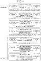
- FIG. 4 is a state transition diagram illustrating the relationship between the mode setting condition and the mode release condition of each display mode, and data having a hierarchical structure that gives a level of priority to each display mode.
- the relationship illustrated in this state transition diagram is stored in the storage unit 102, and various data may be extracted from the storage unit 102.
- each mode setting condition and mode release condition or in other words, the switching condition for switching from “inactive” to “active” and the switching condition for switching from “active” to “inactive” are as described below. Note that whether each mode setting condition or mode release condition is satisfied is determined based on the operating state of each switch 20 to 22 and the direction indicator 40, the detection result of the shift position sensor 30, and an input signal from the external terminal 300 that are inputted to the display control device 100.
- Both “1: First maintenance mode” and “2: Second maintenance mode” are both set as one mode of the maintenance modes, and when a maintenance mode is to be set, the maintenance mode is selectively set from these modes. For example, when a specified mode setting condition is satisfied, first, the first maintenance mode has "ownership” and the first maintenance mode is set. After that, in a case where it is desired to set the second maintenance mode, the ON/MENU switch 22 is pressed. As a result, the first maintenance mode has "no ownership” and the second maintenance mode has "ownership", so the second maintenance mode is set after exiting the first maintenance mode. In this way, one of the first maintenance mode and the second maintenance mode may be selected and set as the maintenance mode.
- the shift position is "P” and the maintenance mode setting instruction command is inputted to the display control device 100 from the external terminal 300
- the shift position has "ownership”.
- the first maintenance mode is switched from “inactive” to “active”, and the first maintenance mode is set.
- the first maintenance mode is set to have "ownership” and is switched from “inactive” to “active”. This makes it possible to set the first maintenance mode without the external terminal 300.
- the various switches 20 to 22 may be arbitrarily set.
- the first maintenance mode is set to have "no ownership” and the first maintenance mode Is released.
- the second maintenance mode is set to have "ownership” and is switched from "inactive” to "active”.
- the second maintenance mode is set after exiting the first maintenance mode.
- a reference icon is displayed on the display screen of the electronic mirror 200 as described above, so it becomes possible to correct deviation of the rear guide lines by operating the cross switch 20 in the up or down direction.
- the second maintenance mode is set to have "no ownership".
- the setting of the second maintenance mode is release from being “active” and is set to be “inactive”.
- the ON/MENU switch 22 is pressed while the shift position is "P"
- the first maintenance mode is set first, and then after that, the second maintenance mode is set. Therefore, first, in the first maintenance mode, for example, correction of the roll deviation of the cameras 10, 11 is performed, and then after that, in the second maintenance mode, for example, correction of the deviation of the rear guide lines of the cameras 10, 11 is performed, and in this way, maintenance may be performed in order. Moreover, switching of the first maintenance mode and the second maintenance mode may be performed in the maintenance mode, so each item of maintenance can be continuously or repeatedly performed without performing an operation for entering the maintenance mode again. For example, transition from the first maintenance mode to the second maintenance mode and transition from the second maintenance mode to the first maintenance mode may be performed by pressing the ON/MENU switch 22, so setting the maintenance mode may be easily performed.
- the mode setting condition is that the shift position is "R”, or in other words, the reverse position.
- the reverse display mode together with being set to have “ownership”
- the reverse display is switched from “inactive” to "active”
- a wide-angle display during reverse driving is performed.
- the reverse display together with being set to have “no ownership”
- the wide field display mode when the operating states of the various switches 20 to 22 satisfy specified mode setting conditions, the wide field display mode is set to have "ownership” and is switched from “inactive” to "active". When this mode is set, a wide-angle display for cautious driving is performed.
- An operating state that satisfies a specified mode setting condition may be arbitrarily set; however, here a case is presumed in which the cross switch 20 is operated while the LR switch 21 is in the neutral position.
- the mode when the operating states of the various switches 20 to 22 satisfy a specified mode release condition after the wide field display mode has been set, the mode is set to have "no ownership" and is switched from “active” to "inactive” and the wide field display mode is released.
- An operating state that satisfies a specified mode release condition may also be arbitrarily set; however, here a case is presumed in which the cross switch 20 is operated while the LR switch 21 is in the neutral position.
- the mode is automatically released after use. Therefore, even in a case in which the elapsed time measured by the timer built in the display control device 100 reaches a specified time after the wide field display mode has been set, the mode is switched from "active" to "inactive” and the wide field display mode is released.
- the mode setting condition is that IG 2 is OFF and a door is opened; and when this condition is satisfied, the door open mode is switched from inactive to active, and the wide-angle display when a person is getting out of the vehicle.
- the mode release condition is that the IG 2 is not turned OFF, and when this condition is satisfied, the door open mode is switched from active to inactive.
- the condition for having "ownership” is the same as the condition for being “active”
- the condition for having "no ownership” is the same as the condition for being "inactive”.
- the left/right turn mode when the operating state of the direction indicator 40 satisfies a specified mode setting condition, the left/right turn mode is set to have "ownership" and is switched from inactive" to "active". When this display mode is set, a wide-angle display for turning left or right is performed. Moreover, in a case where the operation of the direction indicator 40 is released after the left/right turn mode has been set and it is no longer necessary to maintain the mode, the mode is automatically released.
- the left/right turn mode is set to have “no ownership” and is switched from “active” to "inactive”. As a result, the left/right turn mode is canceled.
- various mode settings may be performed for each the right-side mirror 201 and the left-side mirror 202. Therefore, for example, when turning right, only the right-side mirror 201 is displayed using a wide-angle display, and when turning left, only the left-side mirror 202 is displayed using a wide-angle display.
- “7: Normal driving mode” the mode is set in a case where none of the modes 1 to 6 described above has “ownership”. Moreover, when viewed from the aspect of the transition state, “7: normal driving mode” is set when none of the other various modes 1 to 6 are “active". In other words, if none of the above-mentioned various display modes 1 to 6 is set to have “ownership” or is set to be “active”, “7: normal driving mode” is switched from “inactive” to "active”. Then, when any one of the 1 to 6 described above is set to have “ownership” or is set to be “active”, the normal driving mode is set to be “inactive”. As a result, when none of the display modes 1 to 6 described above is set, the normal driving mode is set and the optical angle display is performed.
- the mode setting condition and the mode release condition described here are merely examples, and may be replaced with other conditions or other conditions may be added.
- the mode setting condition may also include the shift position being "P", or in other words, the parking position, and the vehicle speed being 0.
- the door open mode it is not essential that the IG 2 is OFF, and only the opening of the door may be used as the mode setting condition.
- a mode setting condition and a mode release condition are determined for each display mode, and the conditions can be arbitrarily set.
- the wide-angle display when it is determined that the mode setting condition for the door open mode is satisfied, the wide-angle display may be performed, and when it is determined that the mode release condition for the door open mode is satisfied, the wide-angle display may be released.
- the mode settings such as described above are performed. More specifically, in the display control device 100, setting the mode is performed by executing a mode setting condition determination process as illustrated in FIG. 5 , and a mode setting process as illustrated in FIG. 6 .
- the display control device 100 executes the mode setting condition determination process illustrated in FIG. 5 for each of the various modes scheduled to be set. This process is executed, for example, at each specified control cycle.
- step S100 an input process for inputting various input signals is performed, and in the next step S110, it is determined whether the mode setting condition is satisfied. Since the mode setting conditions are set for each of the display modes described above, the determination in this step is performed by determining whether the conditions are satisfied. For example, in the case of "5: Door open mode", the mode setting condition is that IG 2 is turned OFF.
- step S120 In a case where an affirmative determination is made, the process proceeds to step S120, "ownership" is set, and the process ends. On the other hand, in a case where a negative determination is made in step S110, the process proceeds to step S130. Then, in step S130, it is determined whether the mode release condition is satisfied. Mode release conditions are set for each of the display modes described above, so the determination in this step is performed by determining whether the conditions are satisfied. For example, in the case of "5: Door open mode", the mode release condition is that IG 2 is not turned OFF.
- step S140 "no ownership" is set, and the process ends.
- step S130 the process ends as is. In this case, the status of having "ownership” and having "no ownership” remains unswitchable, so the current status is maintained.
- the mode setting condition determination process By executing the mode setting condition determination process as described above, it is determined for each display mode whether a state of "ownership” or "no ownership” is set. Then, based on this result, the mode setting process illustrated in FIG. 6 is executed. This process is also executed, for example, at each specified control cycle.
- step S200 it is determined whether "ownership" is set for the display mode having the highest priority, or in other words, "1: First maintenance mode".
- step S205 the first maintenance mode is set and the process ends, and when a negative determination is made, the process proceeds to step S210.
- step S210 it is determined whether "ownership" is set for the display mode having the second highest priority, in other words, "2: Second maintenance mode".
- step S215 the second maintenance mode is set and the process ends, and when a negative determination is made, the process proceeds to step S220.
- step S220 it is determined whether "ownership" is set for the display mode having the third highest priority, in other words, "3: Reverse display mode".
- step S225 the reverse display mode is set and the process ends, and when a negative determination is made, the process proceeds to step S230.
- step S230 and subsequent steps in the same manner as described above, it is determined whether "ownership" is set for each display mode having the highest priority from the fourth highest on, and when an affirmative determination is made, that display mode is set. Then, when a negative determination is made, the same process is repeated for the display mode having the next highest priority. By doing so, even in a case where there is a plurality of modes for which "ownership" is set, the display mode having the highest priority may be set.
- the determination unit 103 executes steps S110 and S130 that are the determination steps in FIG. 5 . Moreover, the process of FIG. 6 is executed by the setting unit 104.
- each display mode when the display control device 100 displays on the electronic mirror 200 is prioritized in a hierarchical structure, and setting the mode is performed according to the priority. Therefore, in a case where there are display modes that satisfy the mode setting conditions, the display mode having the highest priority may be selected from those display modes and that mode may be set.
- the display modes 1 to 7 illustrated in FIG. 3 have been described as an example; however, the display modes described here are merely examples of display modes. In other words, other display modes other than modes 1 to 7 that are illustrated may be included, a part of modes 1 to 7 may be excluded, and other display modes may be included while excluding a part of modes 1 to 7.
- the stop mode is a mode for continuing the display by the electronic mirror 200 for a specified period even after the user finishes driving the vehicle.
- the display by the electronic mirror 200 is not stopped even when the IG 2 is turned OFF, and continues for a specified period based on the power supply from the delay circuit 3.
- the form of the display by the electronic mirror 200 is an optical angle display as in the normal driving mode; however, a wide-angle display may also be used.
- the stop mode when the IG 2 is turned OFF as the mode setting condition, the stop mode is set to have "ownership" and the mode is switched from "inactive" to "active".
- the stop mode is set to have "no ownership" and the mode is switched from “active” to "inactive".
- modes other than the modes illustrated in FIG. 3 may also be included. Note that in the example of FIG. 7 , “ 5 : Door open mode” of the first embodiment illustrated in FIG. 3 is eliminated, and “1: Stop mode” is included instead; and in regard to the other modes, a case is illustrated in which part of the order of priority has been changed. This is also just an example, and other display modes may be included or deleted.
- the user may also be able to select whether to adopt each display mode.
- a display for selecting whether to adopt each display mode is displayed, and the cross switch 20 may be used to select whether to adopt a display mode. This makes it possible to select whether to adopt or not adopt, for example, a reverse display mode, a wide field display, or the like.
- the mode setting condition and the mode release condition may be changed as appropriate.
- the order of priority of each display mode may be changed as appropriate. In other words, even when a plurality of display modes have been prioritized and configured in a hierarchical structure and mode setting conditions are satisfied for the plurality of display modes, by selecting and setting the display mode having the highest priority, it is possible to obtain the effect explained in the embodiment described above.
- the shift position sensor 30, the door sensor 31, and the direction indicator 40 are included as the electronic mirror system, as long a configuration for determining whether the mode setting condition is satisfied is provided, not all configurations are required. Of course, other configurations may also be added.
- an example is given of an electronic mirror system in which the electronic mirror 200 serves the role of a side mirror of a vehicle, or in other words, is an example of a system that is configured by an electronic side mirror.
- the above embodiment may also be applied in a case in which the electronic mirror 200 serves as a rearview mirror of a vehicle, or in other words, constitutes an electronic rearview mirror.
- those that do not need to be applied to a rearview mirror, such as the left/right turn mode may be appropriately excluded.
- the IG 2 is given as an example of a start switch that is a switch that enables the vehicle to start; however, in an electric vehicle or a hybrid vehicle, a push switch or the like is used as a start switch.
Landscapes
- Engineering & Computer Science (AREA)
- Multimedia (AREA)
- Mechanical Engineering (AREA)
- Rear-View Mirror Devices That Are Mounted On The Exterior Of The Vehicle (AREA)
- Controls And Circuits For Display Device (AREA)
- Fittings On The Vehicle Exterior For Carrying Loads, And Devices For Holding Or Mounting Articles (AREA)
- Closed-Circuit Television Systems (AREA)
Claims (10)
- Dispositif de commande d'affichage qui capture des images vidéo de l'environnement d'un véhicule par une caméra (10, 11) et, en utilisant des données d'image de la caméra, réalise un affichage sur un rétroviseur électronique (200) dans un mode d'affichage sélectionné parmi une pluralité de modes d'affichage, et comprenant :une unité d'entrée (101) dans laquelle des signaux d'entrée sont entrés, les signaux d'entrée incluant des signaux indiquant des états d'actionnement de commutateurs (20 à 22) utilisés pour actionner le rétroviseur électronique et utilisés pour sélectionner un mode d'affichage parmi la pluralité de modes d'affichage à afficher par le rétroviseur électronique ;une unité de stockage (102) qui, avec la priorisation avec une priorité et le stockage de chacun parmi une pluralité de modes d'affichage dans une structure hiérarchique, stocke des conditions de réglage de mode qui sont des conditions pour régler chaque mode d'affichage ;une unité de détermination (S110, S130) pour déterminer si les conditions de réglage de mode sont satisfaites pour chacun parmi la pluralité de modes d'affichage sur la base des signaux d'entrée ; etune unité de réglage (S200 à S265) qui, parmi la pluralité de modes d'affichage, règle un mode d'affichage ayant la plus grande priorité parmi les modes d'affichage pour lesquels les conditions de réglage de mode sont satisfaites, en tant qu'un mode d'affichage à afficher sur le rétroviseur électronique, dans lequell'unité de stockage stocke des conditions de libération de mode qui sont des conditions pour libérer le réglage de chacun parmi la pluralité de modes d'affichage ; l'unité de détermination détermine si la condition de libération de mode est satisfaite ou non pour chacun parmi la pluralité de modes d'affichage sur la base des signaux d'entrée ;l'unité de détermination, pour chacun parmi la pluralité de modes d'affichage, règle un mode d'affichage pour lequel la condition de réglage de mode est satisfaite pour avoir un droit de propriété, et règle un mode d'affichage pour lequel la condition de libération de mode est satisfaite pour n'avoir aucun droit de propriété ; etl'unité de réglage règle le mode d'affichage ayant la plus grande priorité parmi les modes d'affichage de la pluralité de modes d'affichage qui sont réglés pour avoir un droit de propriété pour être le mode d'affichage qui est affiché sur le rétroviseur électronique, caractérisé en ce quedans le rétroviseur électronique, les données d'image dans une plage d'imagerie de la caméra sont partiellement coupées et affichées, et la pluralité de modes d'affichage inclut un mode d'affichage d'un affichage d'angle optique qui affiche en utilisant un angle d'affichage équivalent à un rétroviseur optique, et des modes d'affichage qui réalisent différents affichages spéciaux comme un affichage grand angle qui affiche en utilisant un angle d'affichage plus grand que l'affichage d'angle optique ;le signal d'entrée inclut un signal indiquant une position de rapport et un signal indiquant une commande d'instruction d'un terminal externe (300) prévu à l'extérieur du véhicule ; eten tant que l'un parmi la pluralité de modes d'affichage, il y a un mode de maintenance qui réalise un affichage de maintenance avec une condition incluant la position de rapport étant à une position de stationnement, et un signal indiquant la commande d'instruction étant entrée en tant que la condition de réglage de mode.
- Dispositif de commande d'affichage selon la revendication 1, dans lequelle rétroviseur électronique réalise un affichage à la fois sur un rétroviseur côté droit (201) et un rétroviseur côté gauche (202) ;l'unité de détermination détermine si les conditions de réglage de mode sont satisfaites ou non pour chacun parmi le rétroviseur côté droit et le rétroviseur côté gauche ; etl'unité de réglage, pour chacun parmi le rétroviseur côté droit et le rétroviseur côté gauche, règle le mode d'affichage ayant la plus grande priorité parmi la pluralité de modes d'affichage pour lesquels la condition de réglage de mode est satisfaite pour être le mode d'affichage affiché sur le rétroviseur électronique.
- Dispositif de commande d'affichage selon la revendication 1 ou 2, dans lequelle signal d'entrée inclut un signal d'activation/désactivation depuis un commutateur de démarrage (2) ; eten tant que l'un parmi la pluralité de modes d'affichage, il y a un mode d'arrêt dans lequel un affichage par le rétroviseur électronique est poursuivi pendant une période spécifiée même après la désactivation du commutateur de démarrage, avec une condition incluant que le commutateur de démarrage soit désactivé en tant que la condition de réglage de mode.
- Dispositif de commande d'affichage selon l'une quelconque des revendications 1 à 3, dans lequelle commutateur inclut un commutateur croisé (20) utilisé pour ajuster la position du centre d'affichage de l'image d'affichage du rétroviseur électronique, et un commutateur de réglage (22) pour réaliser un affichage de menu lors de la réalisation de l'affichage spécial ;le mode de maintenance inclut un premier mode de maintenance et un second mode de maintenance ;le premier mode de maintenance réalise un affichage d'image pour corriger un écart de roulis qui est un écart de la direction de rotation par rapport à l'axe central de l'imagerie par la caméra et, au cours du premier mode de maintenance, une correction de l'écart de roulis est réalisée sur la base d'un actionnement du commutateur croisé ;le second mode de maintenance réalise un affichage d'image pour corriger un écart d'angle dans une direction de référence de l'axe central de l'imagerie par la caméra et, au cours du second mode de maintenance, une correction de l'écart d'angle est réalisée sur la base d'un actionnement du commutateur croisé ; etau cours du mode de maintenance, une commutation entre le premier mode de maintenance et le second mode de maintenance est réalisée sur la base de la pression du commutateur de réglage.
- Dispositif de commande d'affichage selon l'une quelconque des revendications 1 à 4, dans lequelle signal d'entrée inclut un signal indiquant une position de rapport ; eten tant que l'un parmi la pluralité de modes d'affichage, il y a un mode d'affichage en marche arrière qui réalise l'affichage grand angle avec une condition qui inclut l'entrée d'un signal qui indique que la position de rapport est une position de marche arrière en tant que la condition de réglage de mode.
- Dispositif de commande d'affichage selon l'une quelconque des revendications 1 à 5, dans lequel
le commutateur inclut un commutateur croisé (20) utilisé pour un ajustement de position du centre d'affichage de l'image d'affichage du rétroviseur électronique ; et en tant que l'un parmi la pluralité de modes d'affichage, il y a un mode d'affichage grand champ qui réalise l'affichage grand angle avec une condition qui inclut l'actionnement du commutateur croisé en tant que la condition de réglage de mode. - Dispositif de commande d'affichage selon l'une quelconque des revendications 1 à 6, dans lequel
en tant que l'un parmi la pluralité de modes d'affichage, il y a un mode d'ouverture de porte qui réalise l'affichage grand angle lorsqu'une condition de réglage de mode d'ouverture de porte est satisfaite sur la base du signal d'entrée. - Dispositif de commande d'affichage selon l'une quelconque des revendications 1 à 7, dans lequelle signal d'entrée inclut un signal qui indique un état d'actionnement d'un clignotant (40) ; eten tant que l'un parmi la pluralité de modes d'affichage, il y a un mode de virage à gauche/à droite qui réalise l'affichage grand angle avec une condition qui inclut l'actionnement du clignotant en tant que la condition de réglage de mode.
- Dispositif de commande d'affichage selon l'une quelconque des revendications 1 à 8, dans lequel
il y a un mode de conduite normale qui réalise l'affichage d'angle optique avec aucune des conditions de réglage de mode des modes d'affichage pour l'affichage spécial n'étant satisfaite en tant que la condition de réglage de mode. - Système de rétroviseur électronique, comprenant :un dispositif de commande d'affichage selon l'une quelconque des revendications 1 à 9 ; etle rétroviseur électronique ;le dispositif de commande d'affichage amenant le rétroviseur électronique à réaliser un affichage en fonction du mode d'affichage réglé par le dispositif de commande d'affichage.
Applications Claiming Priority (2)
| Application Number | Priority Date | Filing Date | Title |
|---|---|---|---|
| JP2018168067A JP7099914B2 (ja) | 2018-09-07 | 2018-09-07 | 電子ミラーの表示制御装置およびそれを備えた電子ミラーシステム |
| PCT/JP2019/034973 WO2020050360A1 (fr) | 2018-09-07 | 2019-09-05 | Dispositif de commande d'affichage pour rétroviseur électronique et système de rétroviseur électronique le comprenant |
Publications (3)
| Publication Number | Publication Date |
|---|---|
| EP3848247A1 EP3848247A1 (fr) | 2021-07-14 |
| EP3848247A4 EP3848247A4 (fr) | 2021-07-14 |
| EP3848247B1 true EP3848247B1 (fr) | 2022-11-30 |
Family
ID=69722416
Family Applications (1)
| Application Number | Title | Priority Date | Filing Date |
|---|---|---|---|
| EP19857209.1A Active EP3848247B1 (fr) | 2018-09-07 | 2019-09-05 | Dispositif de commande d'affichage pour rétroviseur électronique et système de rétroviseur électronique le comprenant |
Country Status (5)
| Country | Link |
|---|---|
| US (1) | US11560095B2 (fr) |
| EP (1) | EP3848247B1 (fr) |
| JP (1) | JP7099914B2 (fr) |
| CN (1) | CN112654533A (fr) |
| WO (1) | WO2020050360A1 (fr) |
Families Citing this family (3)
| Publication number | Priority date | Publication date | Assignee | Title |
|---|---|---|---|---|
| CN218198109U (zh) * | 2019-10-23 | 2023-01-03 | 索尼公司 | 移动装置 |
| WO2022039910A1 (fr) | 2020-08-18 | 2022-02-24 | Mills Randell L | Système et procédé d'augmentation de l'énergie cinétique d'un flux de plasma directionnel |
| CN115593312B (zh) * | 2022-11-16 | 2023-03-24 | 鹰驾科技(深圳)有限公司 | 一种基于环境监测分析的电子后视镜模式切换方法 |
Family Cites Families (21)
| Publication number | Priority date | Publication date | Assignee | Title |
|---|---|---|---|---|
| JP2001344699A (ja) * | 2000-06-01 | 2001-12-14 | Yazaki Corp | 車両位置姿勢検出装置、及びそれを用いた駐車補助装置 |
| JP2003291729A (ja) * | 2002-04-01 | 2003-10-15 | Toyonari Kimura | 移動車両の側面死角解消装置 |
| JP4379148B2 (ja) * | 2004-02-23 | 2009-12-09 | 株式会社エクォス・リサーチ | 後方確認装置 |
| JP2007081932A (ja) * | 2005-09-15 | 2007-03-29 | Auto Network Gijutsu Kenkyusho:Kk | 車両周辺視認装置 |
| JP4888831B2 (ja) | 2006-12-11 | 2012-02-29 | 株式会社デンソー | 車両周辺監視装置 |
| JP4984974B2 (ja) * | 2007-03-02 | 2012-07-25 | 富士通株式会社 | 運転支援システム及び車載装置 |
| JP4866314B2 (ja) * | 2007-08-06 | 2012-02-01 | パナソニック株式会社 | 電子ミラー電源制御システム |
| DE102007044536A1 (de) * | 2007-09-18 | 2009-03-19 | Bayerische Motoren Werke Aktiengesellschaft | Vorrichtung zum Überwachen der Umgebung eines Kraftfahrzeugs |
| JP2010143250A (ja) * | 2008-12-16 | 2010-07-01 | Nissan Motor Co Ltd | 後方視認装置 |
| JP2011131678A (ja) * | 2009-12-24 | 2011-07-07 | Fujitsu Ten Ltd | 画像処理装置、画像処理システム、および、画像処理方法 |
| JP5397697B2 (ja) * | 2010-03-12 | 2014-01-22 | アイシン精機株式会社 | 画像制御装置 |
| CN102420971B (zh) * | 2010-09-27 | 2014-05-28 | 比亚迪股份有限公司 | 倒车辅助系统和倒车辅助方法 |
| DE102010051206A1 (de) * | 2010-11-12 | 2012-05-16 | Valeo Schalter Und Sensoren Gmbh | Verfahren zum Erzeugen eines Bilds einer Fahrzeugumgebung und Abbildungsvorrichtung |
| JP2013095280A (ja) * | 2011-11-01 | 2013-05-20 | Suzuki Motor Corp | 車両の空調装置 |
| JP2013208996A (ja) * | 2012-03-30 | 2013-10-10 | Honda Motor Co Ltd | 自動二輪車におけるミラー構造 |
| JP2015144407A (ja) * | 2013-12-27 | 2015-08-06 | 株式会社Jvcケンウッド | 視界支援装置、視界支援方法、及び視界支援プログラム |
| JP6206395B2 (ja) * | 2014-12-26 | 2017-10-04 | トヨタ自動車株式会社 | 電子ミラー装置 |
| JPWO2016125465A1 (ja) * | 2015-02-02 | 2017-11-09 | パナソニックIpマネジメント株式会社 | 電子ミラー装置とそれを用いた電子ミラーシステム |
| JP6558989B2 (ja) * | 2015-07-16 | 2019-08-14 | 株式会社東海理化電機製作所 | 車両用電子ミラーシステム |
| JP6617462B2 (ja) * | 2015-07-31 | 2019-12-11 | 市光工業株式会社 | 車両周辺視認装置 |
| WO2018008631A1 (fr) * | 2016-07-06 | 2018-01-11 | パナソニックIpマネジメント株式会社 | Appareil électronique à mode de miroir |
-
2018
- 2018-09-07 JP JP2018168067A patent/JP7099914B2/ja active Active
-
2019
- 2019-09-05 EP EP19857209.1A patent/EP3848247B1/fr active Active
- 2019-09-05 CN CN201980058221.5A patent/CN112654533A/zh not_active Withdrawn
- 2019-09-05 WO PCT/JP2019/034973 patent/WO2020050360A1/fr unknown
-
2021
- 2021-03-05 US US17/193,790 patent/US11560095B2/en active Active
Also Published As
| Publication number | Publication date |
|---|---|
| US11560095B2 (en) | 2023-01-24 |
| JP7099914B2 (ja) | 2022-07-12 |
| US20210188177A1 (en) | 2021-06-24 |
| EP3848247A1 (fr) | 2021-07-14 |
| CN112654533A (zh) | 2021-04-13 |
| JP2020040461A (ja) | 2020-03-19 |
| WO2020050360A1 (fr) | 2020-03-12 |
| EP3848247A4 (fr) | 2021-07-14 |
Similar Documents
| Publication | Publication Date | Title |
|---|---|---|
| US11560095B2 (en) | Display control device for electronic mirror, and electronic mirror system including the same | |
| KR100595040B1 (ko) | 차량용 화상 표시장치 | |
| JP4978558B2 (ja) | 車両用表示装置 | |
| US20090128307A1 (en) | Display device and display method for a vehicle | |
| JP2003081014A (ja) | 車両周辺監視装置 | |
| JP2002229542A (ja) | 車載用映像切換装置 | |
| JP2009248918A (ja) | 画像表示装置、画像表示方法及びコンピュータプログラム | |
| US7616104B2 (en) | Notification controller, notification control method and notification information transmitter | |
| US10946800B2 (en) | Image display apparatus for displaying surrounding image of vehicle | |
| EP3572284B1 (fr) | Dispositif d'affichage de l'environnement d'un véhicule | |
| WO2020250525A1 (fr) | Dispositif d'affichage d'informations embarqué | |
| JP2010247645A (ja) | 車載カメラ | |
| US11024011B2 (en) | Image display apparatus and image display method | |
| JP2017058600A (ja) | 表示制御装置、画像表示システム、及び、表示制御方法 | |
| EP3620331B1 (fr) | Dispositif d'affichage de l'environnement d'un véhicule | |
| JP2005145217A (ja) | 車載表示装置及び車両周辺監視装置 | |
| US11372110B2 (en) | Image display apparatus | |
| JP2010030324A (ja) | 操作装置 | |
| CN113119954A (zh) | 用于控制泊车辅助的方法及装置 | |
| US20230376123A1 (en) | Display system | |
| CN104228680A (zh) | 车辆辅助控制系统、控制方法及车辆 | |
| US20200166641A1 (en) | Image display apparatus | |
| JP7116670B2 (ja) | 走行制御装置、制御方法およびプログラム | |
| JP5206512B2 (ja) | 車両用情報表示制御装置 | |
| JP2023091142A (ja) | ヘッドアップディスプレイ装置 |
Legal Events
| Date | Code | Title | Description |
|---|---|---|---|
| STAA | Information on the status of an ep patent application or granted ep patent |
Free format text: STATUS: THE INTERNATIONAL PUBLICATION HAS BEEN MADE |
|
| PUAI | Public reference made under article 153(3) epc to a published international application that has entered the european phase |
Free format text: ORIGINAL CODE: 0009012 |
|
| STAA | Information on the status of an ep patent application or granted ep patent |
Free format text: STATUS: REQUEST FOR EXAMINATION WAS MADE |
|
| STAA | Information on the status of an ep patent application or granted ep patent |
Free format text: STATUS: EXAMINATION IS IN PROGRESS |
|
| 17P | Request for examination filed |
Effective date: 20210329 |
|
| A4 | Supplementary search report drawn up and despatched |
Effective date: 20210520 |
|
| AK | Designated contracting states |
Kind code of ref document: A1 Designated state(s): AL AT BE BG CH CY CZ DE DK EE ES FI FR GB GR HR HU IE IS IT LI LT LU LV MC MK MT NL NO PL PT RO RS SE SI SK SM TR |
|
| 17Q | First examination report despatched |
Effective date: 20210623 |
|
| DAV | Request for validation of the european patent (deleted) | ||
| DAX | Request for extension of the european patent (deleted) | ||
| GRAP | Despatch of communication of intention to grant a patent |
Free format text: ORIGINAL CODE: EPIDOSNIGR1 |
|
| STAA | Information on the status of an ep patent application or granted ep patent |
Free format text: STATUS: GRANT OF PATENT IS INTENDED |
|
| INTG | Intention to grant announced |
Effective date: 20220623 |
|
| GRAS | Grant fee paid |
Free format text: ORIGINAL CODE: EPIDOSNIGR3 |
|
| GRAA | (expected) grant |
Free format text: ORIGINAL CODE: 0009210 |
|
| STAA | Information on the status of an ep patent application or granted ep patent |
Free format text: STATUS: THE PATENT HAS BEEN GRANTED |
|
| AK | Designated contracting states |
Kind code of ref document: B1 Designated state(s): AL AT BE BG CH CY CZ DE DK EE ES FI FR GB GR HR HU IE IS IT LI LT LU LV MC MK MT NL NO PL PT RO RS SE SI SK SM TR |
|
| REG | Reference to a national code |
Ref country code: CH Ref legal event code: EP Ref country code: GB Ref legal event code: FG4D |
|
| REG | Reference to a national code |
Ref country code: AT Ref legal event code: REF Ref document number: 1534438 Country of ref document: AT Kind code of ref document: T Effective date: 20221215 Ref country code: DE Ref legal event code: R096 Ref document number: 602019022716 Country of ref document: DE |
|
| REG | Reference to a national code |
Ref country code: IE Ref legal event code: FG4D |
|
| REG | Reference to a national code |
Ref country code: LT Ref legal event code: MG9D |
|
| REG | Reference to a national code |
Ref country code: NL Ref legal event code: MP Effective date: 20221130 |
|
| PG25 | Lapsed in a contracting state [announced via postgrant information from national office to epo] |
Ref country code: SE Free format text: LAPSE BECAUSE OF FAILURE TO SUBMIT A TRANSLATION OF THE DESCRIPTION OR TO PAY THE FEE WITHIN THE PRESCRIBED TIME-LIMIT Effective date: 20221130 Ref country code: PT Free format text: LAPSE BECAUSE OF FAILURE TO SUBMIT A TRANSLATION OF THE DESCRIPTION OR TO PAY THE FEE WITHIN THE PRESCRIBED TIME-LIMIT Effective date: 20230331 Ref country code: NO Free format text: LAPSE BECAUSE OF FAILURE TO SUBMIT A TRANSLATION OF THE DESCRIPTION OR TO PAY THE FEE WITHIN THE PRESCRIBED TIME-LIMIT Effective date: 20230228 Ref country code: LT Free format text: LAPSE BECAUSE OF FAILURE TO SUBMIT A TRANSLATION OF THE DESCRIPTION OR TO PAY THE FEE WITHIN THE PRESCRIBED TIME-LIMIT Effective date: 20221130 Ref country code: FI Free format text: LAPSE BECAUSE OF FAILURE TO SUBMIT A TRANSLATION OF THE DESCRIPTION OR TO PAY THE FEE WITHIN THE PRESCRIBED TIME-LIMIT Effective date: 20221130 Ref country code: ES Free format text: LAPSE BECAUSE OF FAILURE TO SUBMIT A TRANSLATION OF THE DESCRIPTION OR TO PAY THE FEE WITHIN THE PRESCRIBED TIME-LIMIT Effective date: 20221130 |
|
| REG | Reference to a national code |
Ref country code: AT Ref legal event code: MK05 Ref document number: 1534438 Country of ref document: AT Kind code of ref document: T Effective date: 20221130 |
|
| PG25 | Lapsed in a contracting state [announced via postgrant information from national office to epo] |
Ref country code: RS Free format text: LAPSE BECAUSE OF FAILURE TO SUBMIT A TRANSLATION OF THE DESCRIPTION OR TO PAY THE FEE WITHIN THE PRESCRIBED TIME-LIMIT Effective date: 20221130 Ref country code: PL Free format text: LAPSE BECAUSE OF FAILURE TO SUBMIT A TRANSLATION OF THE DESCRIPTION OR TO PAY THE FEE WITHIN THE PRESCRIBED TIME-LIMIT Effective date: 20221130 Ref country code: LV Free format text: LAPSE BECAUSE OF FAILURE TO SUBMIT A TRANSLATION OF THE DESCRIPTION OR TO PAY THE FEE WITHIN THE PRESCRIBED TIME-LIMIT Effective date: 20221130 Ref country code: IS Free format text: LAPSE BECAUSE OF FAILURE TO SUBMIT A TRANSLATION OF THE DESCRIPTION OR TO PAY THE FEE WITHIN THE PRESCRIBED TIME-LIMIT Effective date: 20230330 Ref country code: HR Free format text: LAPSE BECAUSE OF FAILURE TO SUBMIT A TRANSLATION OF THE DESCRIPTION OR TO PAY THE FEE WITHIN THE PRESCRIBED TIME-LIMIT Effective date: 20221130 Ref country code: GR Free format text: LAPSE BECAUSE OF FAILURE TO SUBMIT A TRANSLATION OF THE DESCRIPTION OR TO PAY THE FEE WITHIN THE PRESCRIBED TIME-LIMIT Effective date: 20230301 |
|
| PG25 | Lapsed in a contracting state [announced via postgrant information from national office to epo] |
Ref country code: NL Free format text: LAPSE BECAUSE OF FAILURE TO SUBMIT A TRANSLATION OF THE DESCRIPTION OR TO PAY THE FEE WITHIN THE PRESCRIBED TIME-LIMIT Effective date: 20221130 |
|
| PG25 | Lapsed in a contracting state [announced via postgrant information from national office to epo] |
Ref country code: SM Free format text: LAPSE BECAUSE OF FAILURE TO SUBMIT A TRANSLATION OF THE DESCRIPTION OR TO PAY THE FEE WITHIN THE PRESCRIBED TIME-LIMIT Effective date: 20221130 Ref country code: RO Free format text: LAPSE BECAUSE OF FAILURE TO SUBMIT A TRANSLATION OF THE DESCRIPTION OR TO PAY THE FEE WITHIN THE PRESCRIBED TIME-LIMIT Effective date: 20221130 Ref country code: EE Free format text: LAPSE BECAUSE OF FAILURE TO SUBMIT A TRANSLATION OF THE DESCRIPTION OR TO PAY THE FEE WITHIN THE PRESCRIBED TIME-LIMIT Effective date: 20221130 Ref country code: DK Free format text: LAPSE BECAUSE OF FAILURE TO SUBMIT A TRANSLATION OF THE DESCRIPTION OR TO PAY THE FEE WITHIN THE PRESCRIBED TIME-LIMIT Effective date: 20221130 Ref country code: CZ Free format text: LAPSE BECAUSE OF FAILURE TO SUBMIT A TRANSLATION OF THE DESCRIPTION OR TO PAY THE FEE WITHIN THE PRESCRIBED TIME-LIMIT Effective date: 20221130 Ref country code: AT Free format text: LAPSE BECAUSE OF FAILURE TO SUBMIT A TRANSLATION OF THE DESCRIPTION OR TO PAY THE FEE WITHIN THE PRESCRIBED TIME-LIMIT Effective date: 20221130 |
|
| PG25 | Lapsed in a contracting state [announced via postgrant information from national office to epo] |
Ref country code: SK Free format text: LAPSE BECAUSE OF FAILURE TO SUBMIT A TRANSLATION OF THE DESCRIPTION OR TO PAY THE FEE WITHIN THE PRESCRIBED TIME-LIMIT Effective date: 20221130 Ref country code: AL Free format text: LAPSE BECAUSE OF FAILURE TO SUBMIT A TRANSLATION OF THE DESCRIPTION OR TO PAY THE FEE WITHIN THE PRESCRIBED TIME-LIMIT Effective date: 20221130 |
|
| REG | Reference to a national code |
Ref country code: DE Ref legal event code: R097 Ref document number: 602019022716 Country of ref document: DE |
|
| PLBE | No opposition filed within time limit |
Free format text: ORIGINAL CODE: 0009261 |
|
| STAA | Information on the status of an ep patent application or granted ep patent |
Free format text: STATUS: NO OPPOSITION FILED WITHIN TIME LIMIT |
|
| 26N | No opposition filed |
Effective date: 20230831 |
|
| PG25 | Lapsed in a contracting state [announced via postgrant information from national office to epo] |
Ref country code: SI Free format text: LAPSE BECAUSE OF FAILURE TO SUBMIT A TRANSLATION OF THE DESCRIPTION OR TO PAY THE FEE WITHIN THE PRESCRIBED TIME-LIMIT Effective date: 20221130 |
|
| REG | Reference to a national code |
Ref country code: DE Ref legal event code: R084 Ref document number: 602019022716 Country of ref document: DE Ref country code: GB Ref legal event code: 746 Effective date: 20240201 |
|
| REG | Reference to a national code |
Ref country code: CH Ref legal event code: PL |
|
| PG25 | Lapsed in a contracting state [announced via postgrant information from national office to epo] |
Ref country code: LU Free format text: LAPSE BECAUSE OF NON-PAYMENT OF DUE FEES Effective date: 20230905 |
|
| REG | Reference to a national code |
Ref country code: BE Ref legal event code: MM Effective date: 20230930 |
|
| PG25 | Lapsed in a contracting state [announced via postgrant information from national office to epo] |
Ref country code: LU Free format text: LAPSE BECAUSE OF NON-PAYMENT OF DUE FEES Effective date: 20230905 Ref country code: IT Free format text: LAPSE BECAUSE OF FAILURE TO SUBMIT A TRANSLATION OF THE DESCRIPTION OR TO PAY THE FEE WITHIN THE PRESCRIBED TIME-LIMIT Effective date: 20221130 Ref country code: MC Free format text: LAPSE BECAUSE OF FAILURE TO SUBMIT A TRANSLATION OF THE DESCRIPTION OR TO PAY THE FEE WITHIN THE PRESCRIBED TIME-LIMIT Effective date: 20221130 |
|
| REG | Reference to a national code |
Ref country code: IE Ref legal event code: MM4A |
|
| PG25 | Lapsed in a contracting state [announced via postgrant information from national office to epo] |
Ref country code: IE Free format text: LAPSE BECAUSE OF NON-PAYMENT OF DUE FEES Effective date: 20230905 |
|
| PG25 | Lapsed in a contracting state [announced via postgrant information from national office to epo] |
Ref country code: CH Free format text: LAPSE BECAUSE OF NON-PAYMENT OF DUE FEES Effective date: 20230930 |
|
| PG25 | Lapsed in a contracting state [announced via postgrant information from national office to epo] |
Ref country code: IE Free format text: LAPSE BECAUSE OF NON-PAYMENT OF DUE FEES Effective date: 20230905 Ref country code: CH Free format text: LAPSE BECAUSE OF NON-PAYMENT OF DUE FEES Effective date: 20230930 |
|
| PG25 | Lapsed in a contracting state [announced via postgrant information from national office to epo] |
Ref country code: BE Free format text: LAPSE BECAUSE OF NON-PAYMENT OF DUE FEES Effective date: 20230930 |
|
| PGFP | Annual fee paid to national office [announced via postgrant information from national office to epo] |
Ref country code: DE Payment date: 20240918 Year of fee payment: 6 |
|
| PGFP | Annual fee paid to national office [announced via postgrant information from national office to epo] |
Ref country code: GB Payment date: 20240920 Year of fee payment: 6 |
|
| PGFP | Annual fee paid to national office [announced via postgrant information from national office to epo] |
Ref country code: FR Payment date: 20240925 Year of fee payment: 6 |