EP3845721A1 - Floor panel and method of producing such a floor panel - Google Patents
Floor panel and method of producing such a floor panel Download PDFInfo
- Publication number
- EP3845721A1 EP3845721A1 EP21153494.6A EP21153494A EP3845721A1 EP 3845721 A1 EP3845721 A1 EP 3845721A1 EP 21153494 A EP21153494 A EP 21153494A EP 3845721 A1 EP3845721 A1 EP 3845721A1
- Authority
- EP
- European Patent Office
- Prior art keywords
- layer
- locking
- floor panel
- panels
- panel according
- Prior art date
- Legal status (The legal status is an assumption and is not a legal conclusion. Google has not performed a legal analysis and makes no representation as to the accuracy of the status listed.)
- Granted
Links
- 238000000034 method Methods 0.000 title abstract description 11
- 230000008878 coupling Effects 0.000 claims abstract description 42
- 238000010168 coupling process Methods 0.000 claims abstract description 42
- 238000005859 coupling reaction Methods 0.000 claims abstract description 42
- 239000000395 magnesium oxide Substances 0.000 claims abstract description 37
- CPLXHLVBOLITMK-UHFFFAOYSA-N magnesium oxide Inorganic materials [Mg]=O CPLXHLVBOLITMK-UHFFFAOYSA-N 0.000 claims abstract description 37
- AXZKOIWUVFPNLO-UHFFFAOYSA-N magnesium;oxygen(2-) Chemical compound [O-2].[Mg+2] AXZKOIWUVFPNLO-UHFFFAOYSA-N 0.000 claims abstract description 37
- 239000010410 layer Substances 0.000 claims description 182
- 239000012792 core layer Substances 0.000 claims description 56
- 239000011152 fibreglass Substances 0.000 claims description 23
- CSNNHWWHGAXBCP-UHFFFAOYSA-L Magnesium sulfate Chemical compound [Mg+2].[O-][S+2]([O-])([O-])[O-] CSNNHWWHGAXBCP-UHFFFAOYSA-L 0.000 claims description 18
- 239000000463 material Substances 0.000 claims description 18
- TWRXJAOTZQYOKJ-UHFFFAOYSA-L Magnesium chloride Chemical compound [Mg+2].[Cl-].[Cl-] TWRXJAOTZQYOKJ-UHFFFAOYSA-L 0.000 claims description 16
- 230000000694 effects Effects 0.000 claims description 14
- 230000003014 reinforcing effect Effects 0.000 claims description 14
- 239000011230 binding agent Substances 0.000 claims description 11
- 230000002787 reinforcement Effects 0.000 claims description 11
- 229910052943 magnesium sulfate Inorganic materials 0.000 claims description 9
- 235000019341 magnesium sulphate Nutrition 0.000 claims description 9
- 239000000758 substrate Substances 0.000 claims description 9
- 229910001629 magnesium chloride Inorganic materials 0.000 claims description 8
- 239000002023 wood Substances 0.000 claims description 6
- 229910052500 inorganic mineral Inorganic materials 0.000 claims description 5
- 235000010755 mineral Nutrition 0.000 claims description 5
- 239000011707 mineral Substances 0.000 claims description 5
- 239000002356 single layer Substances 0.000 claims description 4
- 229920000642 polymer Polymers 0.000 claims description 3
- 229920003043 Cellulose fiber Polymers 0.000 claims description 2
- 239000004800 polyvinyl chloride Substances 0.000 description 13
- 229920000915 polyvinyl chloride Polymers 0.000 description 12
- XLYOFNOQVPJJNP-UHFFFAOYSA-N water Substances O XLYOFNOQVPJJNP-UHFFFAOYSA-N 0.000 description 10
- 229920002522 Wood fibre Polymers 0.000 description 9
- 238000004519 manufacturing process Methods 0.000 description 9
- 230000000295 complement effect Effects 0.000 description 7
- 239000004576 sand Substances 0.000 description 6
- 239000000203 mixture Substances 0.000 description 5
- 230000006872 improvement Effects 0.000 description 4
- WRUGWIBCXHJTDG-UHFFFAOYSA-L magnesium sulfate heptahydrate Chemical compound O.O.O.O.O.O.O.[Mg+2].[O-]S([O-])(=O)=O WRUGWIBCXHJTDG-UHFFFAOYSA-L 0.000 description 4
- 238000005488 sandblasting Methods 0.000 description 4
- 229920001807 Urea-formaldehyde Polymers 0.000 description 3
- 239000001164 aluminium sulphate Substances 0.000 description 3
- 235000011128 aluminium sulphate Nutrition 0.000 description 3
- 230000008901 benefit Effects 0.000 description 3
- 238000000576 coating method Methods 0.000 description 3
- BUACSMWVFUNQET-UHFFFAOYSA-H dialuminum;trisulfate;hydrate Chemical compound O.[Al+3].[Al+3].[O-]S([O-])(=O)=O.[O-]S([O-])(=O)=O.[O-]S([O-])(=O)=O BUACSMWVFUNQET-UHFFFAOYSA-H 0.000 description 3
- 239000010881 fly ash Substances 0.000 description 3
- 239000003607 modifier Substances 0.000 description 3
- 238000004026 adhesive bonding Methods 0.000 description 2
- 239000011248 coating agent Substances 0.000 description 2
- 230000021615 conjugation Effects 0.000 description 2
- 239000011162 core material Substances 0.000 description 2
- 230000002349 favourable effect Effects 0.000 description 2
- 239000000835 fiber Substances 0.000 description 2
- 230000009970 fire resistant effect Effects 0.000 description 2
- 239000003292 glue Substances 0.000 description 2
- VTHJTEIRLNZDEV-UHFFFAOYSA-L magnesium dihydroxide Chemical compound [OH-].[OH-].[Mg+2] VTHJTEIRLNZDEV-UHFFFAOYSA-L 0.000 description 2
- 239000000347 magnesium hydroxide Substances 0.000 description 2
- 229910001862 magnesium hydroxide Inorganic materials 0.000 description 2
- 239000002245 particle Substances 0.000 description 2
- ODGAOXROABLFNM-UHFFFAOYSA-N polynoxylin Chemical compound O=C.NC(N)=O ODGAOXROABLFNM-UHFFFAOYSA-N 0.000 description 2
- 229920005989 resin Polymers 0.000 description 2
- 239000011347 resin Substances 0.000 description 2
- 125000000391 vinyl group Chemical group [H]C([*])=C([H])[H] 0.000 description 2
- 229920002554 vinyl polymer Polymers 0.000 description 2
- 235000017166 Bambusa arundinacea Nutrition 0.000 description 1
- 235000017491 Bambusa tulda Nutrition 0.000 description 1
- 241001330002 Bambuseae Species 0.000 description 1
- 229920000877 Melamine resin Polymers 0.000 description 1
- 235000015334 Phyllostachys viridis Nutrition 0.000 description 1
- 208000003251 Pruritus Diseases 0.000 description 1
- 239000000654 additive Substances 0.000 description 1
- 239000011425 bamboo Substances 0.000 description 1
- 238000005452 bending Methods 0.000 description 1
- 230000009286 beneficial effect Effects 0.000 description 1
- 229920002678 cellulose Polymers 0.000 description 1
- 239000001913 cellulose Substances 0.000 description 1
- 239000000919 ceramic Substances 0.000 description 1
- 238000004140 cleaning Methods 0.000 description 1
- 230000006835 compression Effects 0.000 description 1
- 238000007906 compression Methods 0.000 description 1
- 229910052593 corundum Inorganic materials 0.000 description 1
- 239000010431 corundum Substances 0.000 description 1
- 230000001627 detrimental effect Effects 0.000 description 1
- 230000009977 dual effect Effects 0.000 description 1
- 238000009408 flooring Methods 0.000 description 1
- 238000007373 indentation Methods 0.000 description 1
- 238000009434 installation Methods 0.000 description 1
- 230000007803 itching Effects 0.000 description 1
- 239000004922 lacquer Substances 0.000 description 1
- 230000005923 long-lasting effect Effects 0.000 description 1
- JDSHMPZPIAZGSV-UHFFFAOYSA-N melamine Chemical compound NC1=NC(N)=NC(N)=N1 JDSHMPZPIAZGSV-UHFFFAOYSA-N 0.000 description 1
- 239000004014 plasticizer Substances 0.000 description 1
- 230000008569 process Effects 0.000 description 1
- 230000003678 scratch resistant effect Effects 0.000 description 1
- 239000002002 slurry Substances 0.000 description 1
- 239000010902 straw Substances 0.000 description 1
- 239000012815 thermoplastic material Substances 0.000 description 1
Images


Classifications
-
- E—FIXED CONSTRUCTIONS
- E04—BUILDING
- E04F—FINISHING WORK ON BUILDINGS, e.g. STAIRS, FLOORS
- E04F15/00—Flooring
- E04F15/02—Flooring or floor layers composed of a number of similar elements
-
- B—PERFORMING OPERATIONS; TRANSPORTING
- B32—LAYERED PRODUCTS
- B32B—LAYERED PRODUCTS, i.e. PRODUCTS BUILT-UP OF STRATA OF FLAT OR NON-FLAT, e.g. CELLULAR OR HONEYCOMB, FORM
- B32B13/00—Layered products comprising a a layer of water-setting substance, e.g. concrete, plaster, asbestos cement, or like builders' material
- B32B13/02—Layered products comprising a a layer of water-setting substance, e.g. concrete, plaster, asbestos cement, or like builders' material with fibres or particles being present as additives in the layer
-
- B—PERFORMING OPERATIONS; TRANSPORTING
- B32—LAYERED PRODUCTS
- B32B—LAYERED PRODUCTS, i.e. PRODUCTS BUILT-UP OF STRATA OF FLAT OR NON-FLAT, e.g. CELLULAR OR HONEYCOMB, FORM
- B32B13/00—Layered products comprising a a layer of water-setting substance, e.g. concrete, plaster, asbestos cement, or like builders' material
- B32B13/04—Layered products comprising a a layer of water-setting substance, e.g. concrete, plaster, asbestos cement, or like builders' material comprising such water setting substance as the main or only constituent of a layer, which is next to another layer of the same or of a different material
- B32B13/08—Layered products comprising a a layer of water-setting substance, e.g. concrete, plaster, asbestos cement, or like builders' material comprising such water setting substance as the main or only constituent of a layer, which is next to another layer of the same or of a different material of paper or cardboard
-
- B—PERFORMING OPERATIONS; TRANSPORTING
- B32—LAYERED PRODUCTS
- B32B—LAYERED PRODUCTS, i.e. PRODUCTS BUILT-UP OF STRATA OF FLAT OR NON-FLAT, e.g. CELLULAR OR HONEYCOMB, FORM
- B32B13/00—Layered products comprising a a layer of water-setting substance, e.g. concrete, plaster, asbestos cement, or like builders' material
- B32B13/04—Layered products comprising a a layer of water-setting substance, e.g. concrete, plaster, asbestos cement, or like builders' material comprising such water setting substance as the main or only constituent of a layer, which is next to another layer of the same or of a different material
- B32B13/12—Layered products comprising a a layer of water-setting substance, e.g. concrete, plaster, asbestos cement, or like builders' material comprising such water setting substance as the main or only constituent of a layer, which is next to another layer of the same or of a different material of synthetic resin
-
- B—PERFORMING OPERATIONS; TRANSPORTING
- B32—LAYERED PRODUCTS
- B32B—LAYERED PRODUCTS, i.e. PRODUCTS BUILT-UP OF STRATA OF FLAT OR NON-FLAT, e.g. CELLULAR OR HONEYCOMB, FORM
- B32B13/00—Layered products comprising a a layer of water-setting substance, e.g. concrete, plaster, asbestos cement, or like builders' material
- B32B13/14—Layered products comprising a a layer of water-setting substance, e.g. concrete, plaster, asbestos cement, or like builders' material next to a fibrous or filamentary layer
-
- B—PERFORMING OPERATIONS; TRANSPORTING
- B32—LAYERED PRODUCTS
- B32B—LAYERED PRODUCTS, i.e. PRODUCTS BUILT-UP OF STRATA OF FLAT OR NON-FLAT, e.g. CELLULAR OR HONEYCOMB, FORM
- B32B27/00—Layered products comprising a layer of synthetic resin
- B32B27/06—Layered products comprising a layer of synthetic resin as the main or only constituent of a layer, which is next to another layer of the same or of a different material
- B32B27/08—Layered products comprising a layer of synthetic resin as the main or only constituent of a layer, which is next to another layer of the same or of a different material of synthetic resin
-
- B—PERFORMING OPERATIONS; TRANSPORTING
- B32—LAYERED PRODUCTS
- B32B—LAYERED PRODUCTS, i.e. PRODUCTS BUILT-UP OF STRATA OF FLAT OR NON-FLAT, e.g. CELLULAR OR HONEYCOMB, FORM
- B32B27/00—Layered products comprising a layer of synthetic resin
- B32B27/30—Layered products comprising a layer of synthetic resin comprising vinyl (co)polymers; comprising acrylic (co)polymers
- B32B27/304—Layered products comprising a layer of synthetic resin comprising vinyl (co)polymers; comprising acrylic (co)polymers comprising vinyl halide (co)polymers, e.g. PVC, PVDC, PVF, PVDF
-
- B—PERFORMING OPERATIONS; TRANSPORTING
- B32—LAYERED PRODUCTS
- B32B—LAYERED PRODUCTS, i.e. PRODUCTS BUILT-UP OF STRATA OF FLAT OR NON-FLAT, e.g. CELLULAR OR HONEYCOMB, FORM
- B32B29/00—Layered products comprising a layer of paper or cardboard
- B32B29/002—Layered products comprising a layer of paper or cardboard as the main or only constituent of a layer, which is next to another layer of the same or of a different material
- B32B29/005—Layered products comprising a layer of paper or cardboard as the main or only constituent of a layer, which is next to another layer of the same or of a different material next to another layer of paper or cardboard layer
-
- B—PERFORMING OPERATIONS; TRANSPORTING
- B32—LAYERED PRODUCTS
- B32B—LAYERED PRODUCTS, i.e. PRODUCTS BUILT-UP OF STRATA OF FLAT OR NON-FLAT, e.g. CELLULAR OR HONEYCOMB, FORM
- B32B3/00—Layered products comprising a layer with external or internal discontinuities or unevennesses, or a layer of non-planar form; Layered products having particular features of form
- B32B3/02—Layered products comprising a layer with external or internal discontinuities or unevennesses, or a layer of non-planar form; Layered products having particular features of form characterised by features of form at particular places, e.g. in edge regions
- B32B3/06—Layered products comprising a layer with external or internal discontinuities or unevennesses, or a layer of non-planar form; Layered products having particular features of form characterised by features of form at particular places, e.g. in edge regions for securing layers together; for attaching the product to another member, e.g. to a support, or to another product, e.g. groove/tongue, interlocking
-
- B—PERFORMING OPERATIONS; TRANSPORTING
- B32—LAYERED PRODUCTS
- B32B—LAYERED PRODUCTS, i.e. PRODUCTS BUILT-UP OF STRATA OF FLAT OR NON-FLAT, e.g. CELLULAR OR HONEYCOMB, FORM
- B32B37/00—Methods or apparatus for laminating, e.g. by curing or by ultrasonic bonding
- B32B37/02—Methods or apparatus for laminating, e.g. by curing or by ultrasonic bonding characterised by a sequence of laminating steps, e.g. by adding new layers at consecutive laminating stations
-
- B—PERFORMING OPERATIONS; TRANSPORTING
- B32—LAYERED PRODUCTS
- B32B—LAYERED PRODUCTS, i.e. PRODUCTS BUILT-UP OF STRATA OF FLAT OR NON-FLAT, e.g. CELLULAR OR HONEYCOMB, FORM
- B32B38/00—Ancillary operations in connection with laminating processes
- B32B38/0012—Mechanical treatment, e.g. roughening, deforming, stretching
-
- B—PERFORMING OPERATIONS; TRANSPORTING
- B32—LAYERED PRODUCTS
- B32B—LAYERED PRODUCTS, i.e. PRODUCTS BUILT-UP OF STRATA OF FLAT OR NON-FLAT, e.g. CELLULAR OR HONEYCOMB, FORM
- B32B5/00—Layered products characterised by the non- homogeneity or physical structure, i.e. comprising a fibrous, filamentary, particulate or foam layer; Layered products characterised by having a layer differing constitutionally or physically in different parts
- B32B5/02—Layered products characterised by the non- homogeneity or physical structure, i.e. comprising a fibrous, filamentary, particulate or foam layer; Layered products characterised by having a layer differing constitutionally or physically in different parts characterised by structural features of a fibrous or filamentary layer
- B32B5/022—Non-woven fabric
-
- B—PERFORMING OPERATIONS; TRANSPORTING
- B32—LAYERED PRODUCTS
- B32B—LAYERED PRODUCTS, i.e. PRODUCTS BUILT-UP OF STRATA OF FLAT OR NON-FLAT, e.g. CELLULAR OR HONEYCOMB, FORM
- B32B5/00—Layered products characterised by the non- homogeneity or physical structure, i.e. comprising a fibrous, filamentary, particulate or foam layer; Layered products characterised by having a layer differing constitutionally or physically in different parts
- B32B5/02—Layered products characterised by the non- homogeneity or physical structure, i.e. comprising a fibrous, filamentary, particulate or foam layer; Layered products characterised by having a layer differing constitutionally or physically in different parts characterised by structural features of a fibrous or filamentary layer
- B32B5/024—Woven fabric
-
- B—PERFORMING OPERATIONS; TRANSPORTING
- B32—LAYERED PRODUCTS
- B32B—LAYERED PRODUCTS, i.e. PRODUCTS BUILT-UP OF STRATA OF FLAT OR NON-FLAT, e.g. CELLULAR OR HONEYCOMB, FORM
- B32B5/00—Layered products characterised by the non- homogeneity or physical structure, i.e. comprising a fibrous, filamentary, particulate or foam layer; Layered products characterised by having a layer differing constitutionally or physically in different parts
- B32B5/02—Layered products characterised by the non- homogeneity or physical structure, i.e. comprising a fibrous, filamentary, particulate or foam layer; Layered products characterised by having a layer differing constitutionally or physically in different parts characterised by structural features of a fibrous or filamentary layer
- B32B5/028—Net structure, e.g. spaced apart filaments bonded at the crossing points
-
- B—PERFORMING OPERATIONS; TRANSPORTING
- B32—LAYERED PRODUCTS
- B32B—LAYERED PRODUCTS, i.e. PRODUCTS BUILT-UP OF STRATA OF FLAT OR NON-FLAT, e.g. CELLULAR OR HONEYCOMB, FORM
- B32B5/00—Layered products characterised by the non- homogeneity or physical structure, i.e. comprising a fibrous, filamentary, particulate or foam layer; Layered products characterised by having a layer differing constitutionally or physically in different parts
- B32B5/22—Layered products characterised by the non- homogeneity or physical structure, i.e. comprising a fibrous, filamentary, particulate or foam layer; Layered products characterised by having a layer differing constitutionally or physically in different parts characterised by the presence of two or more layers which are next to each other and are fibrous, filamentary, formed of particles or foamed
- B32B5/24—Layered products characterised by the non- homogeneity or physical structure, i.e. comprising a fibrous, filamentary, particulate or foam layer; Layered products characterised by having a layer differing constitutionally or physically in different parts characterised by the presence of two or more layers which are next to each other and are fibrous, filamentary, formed of particles or foamed one layer being a fibrous or filamentary layer
- B32B5/26—Layered products characterised by the non- homogeneity or physical structure, i.e. comprising a fibrous, filamentary, particulate or foam layer; Layered products characterised by having a layer differing constitutionally or physically in different parts characterised by the presence of two or more layers which are next to each other and are fibrous, filamentary, formed of particles or foamed one layer being a fibrous or filamentary layer another layer next to it also being fibrous or filamentary
-
- B—PERFORMING OPERATIONS; TRANSPORTING
- B32—LAYERED PRODUCTS
- B32B—LAYERED PRODUCTS, i.e. PRODUCTS BUILT-UP OF STRATA OF FLAT OR NON-FLAT, e.g. CELLULAR OR HONEYCOMB, FORM
- B32B7/00—Layered products characterised by the relation between layers; Layered products characterised by the relative orientation of features between layers, or by the relative values of a measurable parameter between layers, i.e. products comprising layers having different physical, chemical or physicochemical properties; Layered products characterised by the interconnection of layers
- B32B7/02—Physical, chemical or physicochemical properties
-
- B—PERFORMING OPERATIONS; TRANSPORTING
- B32—LAYERED PRODUCTS
- B32B—LAYERED PRODUCTS, i.e. PRODUCTS BUILT-UP OF STRATA OF FLAT OR NON-FLAT, e.g. CELLULAR OR HONEYCOMB, FORM
- B32B7/00—Layered products characterised by the relation between layers; Layered products characterised by the relative orientation of features between layers, or by the relative values of a measurable parameter between layers, i.e. products comprising layers having different physical, chemical or physicochemical properties; Layered products characterised by the interconnection of layers
- B32B7/04—Interconnection of layers
- B32B7/12—Interconnection of layers using interposed adhesives or interposed materials with bonding properties
-
- B—PERFORMING OPERATIONS; TRANSPORTING
- B32—LAYERED PRODUCTS
- B32B—LAYERED PRODUCTS, i.e. PRODUCTS BUILT-UP OF STRATA OF FLAT OR NON-FLAT, e.g. CELLULAR OR HONEYCOMB, FORM
- B32B9/00—Layered products comprising a layer of a particular substance not covered by groups B32B11/00 - B32B29/00
- B32B9/04—Layered products comprising a layer of a particular substance not covered by groups B32B11/00 - B32B29/00 comprising such particular substance as the main or only constituent of a layer, which is next to another layer of the same or of a different material
- B32B9/045—Layered products comprising a layer of a particular substance not covered by groups B32B11/00 - B32B29/00 comprising such particular substance as the main or only constituent of a layer, which is next to another layer of the same or of a different material of synthetic resin
-
- B—PERFORMING OPERATIONS; TRANSPORTING
- B32—LAYERED PRODUCTS
- B32B—LAYERED PRODUCTS, i.e. PRODUCTS BUILT-UP OF STRATA OF FLAT OR NON-FLAT, e.g. CELLULAR OR HONEYCOMB, FORM
- B32B9/00—Layered products comprising a layer of a particular substance not covered by groups B32B11/00 - B32B29/00
- B32B9/04—Layered products comprising a layer of a particular substance not covered by groups B32B11/00 - B32B29/00 comprising such particular substance as the main or only constituent of a layer, which is next to another layer of the same or of a different material
- B32B9/047—Layered products comprising a layer of a particular substance not covered by groups B32B11/00 - B32B29/00 comprising such particular substance as the main or only constituent of a layer, which is next to another layer of the same or of a different material made of fibres or filaments
-
- B—PERFORMING OPERATIONS; TRANSPORTING
- B32—LAYERED PRODUCTS
- B32B—LAYERED PRODUCTS, i.e. PRODUCTS BUILT-UP OF STRATA OF FLAT OR NON-FLAT, e.g. CELLULAR OR HONEYCOMB, FORM
- B32B9/00—Layered products comprising a layer of a particular substance not covered by groups B32B11/00 - B32B29/00
- B32B9/04—Layered products comprising a layer of a particular substance not covered by groups B32B11/00 - B32B29/00 comprising such particular substance as the main or only constituent of a layer, which is next to another layer of the same or of a different material
- B32B9/06—Layered products comprising a layer of a particular substance not covered by groups B32B11/00 - B32B29/00 comprising such particular substance as the main or only constituent of a layer, which is next to another layer of the same or of a different material of paper or cardboard
-
- C—CHEMISTRY; METALLURGY
- C04—CEMENTS; CONCRETE; ARTIFICIAL STONE; CERAMICS; REFRACTORIES
- C04B—LIME, MAGNESIA; SLAG; CEMENTS; COMPOSITIONS THEREOF, e.g. MORTARS, CONCRETE OR LIKE BUILDING MATERIALS; ARTIFICIAL STONE; CERAMICS; REFRACTORIES; TREATMENT OF NATURAL STONE
- C04B28/00—Compositions of mortars, concrete or artificial stone, containing inorganic binders or the reaction product of an inorganic and an organic binder, e.g. polycarboxylate cements
- C04B28/30—Compositions of mortars, concrete or artificial stone, containing inorganic binders or the reaction product of an inorganic and an organic binder, e.g. polycarboxylate cements containing magnesium cements or similar cements
- C04B28/32—Magnesium oxychloride cements, e.g. Sorel cement
-
- E—FIXED CONSTRUCTIONS
- E04—BUILDING
- E04F—FINISHING WORK ON BUILDINGS, e.g. STAIRS, FLOORS
- E04F15/00—Flooring
- E04F15/02—Flooring or floor layers composed of a number of similar elements
- E04F15/02038—Flooring or floor layers composed of a number of similar elements characterised by tongue and groove connections between neighbouring flooring elements
-
- E—FIXED CONSTRUCTIONS
- E04—BUILDING
- E04F—FINISHING WORK ON BUILDINGS, e.g. STAIRS, FLOORS
- E04F15/00—Flooring
- E04F15/02—Flooring or floor layers composed of a number of similar elements
- E04F15/02177—Floor elements for use at a specific location
- E04F15/02188—Floor elements for use at a specific location for use in wet rooms
-
- E—FIXED CONSTRUCTIONS
- E04—BUILDING
- E04F—FINISHING WORK ON BUILDINGS, e.g. STAIRS, FLOORS
- E04F15/00—Flooring
- E04F15/02—Flooring or floor layers composed of a number of similar elements
- E04F15/10—Flooring or floor layers composed of a number of similar elements of other materials, e.g. fibrous or chipped materials, organic plastics, magnesite tiles, hardboard, or with a top layer of other materials
- E04F15/102—Flooring or floor layers composed of a number of similar elements of other materials, e.g. fibrous or chipped materials, organic plastics, magnesite tiles, hardboard, or with a top layer of other materials of fibrous or chipped materials, e.g. bonded with synthetic resins
-
- B—PERFORMING OPERATIONS; TRANSPORTING
- B32—LAYERED PRODUCTS
- B32B—LAYERED PRODUCTS, i.e. PRODUCTS BUILT-UP OF STRATA OF FLAT OR NON-FLAT, e.g. CELLULAR OR HONEYCOMB, FORM
- B32B13/00—Layered products comprising a a layer of water-setting substance, e.g. concrete, plaster, asbestos cement, or like builders' material
-
- B—PERFORMING OPERATIONS; TRANSPORTING
- B32—LAYERED PRODUCTS
- B32B—LAYERED PRODUCTS, i.e. PRODUCTS BUILT-UP OF STRATA OF FLAT OR NON-FLAT, e.g. CELLULAR OR HONEYCOMB, FORM
- B32B2250/00—Layers arrangement
- B32B2250/05—5 or more layers
-
- B—PERFORMING OPERATIONS; TRANSPORTING
- B32—LAYERED PRODUCTS
- B32B—LAYERED PRODUCTS, i.e. PRODUCTS BUILT-UP OF STRATA OF FLAT OR NON-FLAT, e.g. CELLULAR OR HONEYCOMB, FORM
- B32B2255/00—Coating on the layer surface
- B32B2255/02—Coating on the layer surface on fibrous or filamentary layer
-
- B—PERFORMING OPERATIONS; TRANSPORTING
- B32—LAYERED PRODUCTS
- B32B—LAYERED PRODUCTS, i.e. PRODUCTS BUILT-UP OF STRATA OF FLAT OR NON-FLAT, e.g. CELLULAR OR HONEYCOMB, FORM
- B32B2255/00—Coating on the layer surface
- B32B2255/26—Polymeric coating
-
- B—PERFORMING OPERATIONS; TRANSPORTING
- B32—LAYERED PRODUCTS
- B32B—LAYERED PRODUCTS, i.e. PRODUCTS BUILT-UP OF STRATA OF FLAT OR NON-FLAT, e.g. CELLULAR OR HONEYCOMB, FORM
- B32B2260/00—Layered product comprising an impregnated, embedded, or bonded layer wherein the layer comprises an impregnation, embedding, or binder material
- B32B2260/02—Composition of the impregnated, bonded or embedded layer
- B32B2260/028—Paper layer
-
- B—PERFORMING OPERATIONS; TRANSPORTING
- B32—LAYERED PRODUCTS
- B32B—LAYERED PRODUCTS, i.e. PRODUCTS BUILT-UP OF STRATA OF FLAT OR NON-FLAT, e.g. CELLULAR OR HONEYCOMB, FORM
- B32B2260/00—Layered product comprising an impregnated, embedded, or bonded layer wherein the layer comprises an impregnation, embedding, or binder material
- B32B2260/04—Impregnation, embedding, or binder material
- B32B2260/046—Synthetic resin
-
- B—PERFORMING OPERATIONS; TRANSPORTING
- B32—LAYERED PRODUCTS
- B32B—LAYERED PRODUCTS, i.e. PRODUCTS BUILT-UP OF STRATA OF FLAT OR NON-FLAT, e.g. CELLULAR OR HONEYCOMB, FORM
- B32B2262/00—Composition or structural features of fibres which form a fibrous or filamentary layer or are present as additives
- B32B2262/06—Vegetal fibres
- B32B2262/062—Cellulose fibres, e.g. cotton
- B32B2262/065—Lignocellulosic fibres, e.g. jute, sisal, hemp, flax, bamboo
-
- B—PERFORMING OPERATIONS; TRANSPORTING
- B32—LAYERED PRODUCTS
- B32B—LAYERED PRODUCTS, i.e. PRODUCTS BUILT-UP OF STRATA OF FLAT OR NON-FLAT, e.g. CELLULAR OR HONEYCOMB, FORM
- B32B2262/00—Composition or structural features of fibres which form a fibrous or filamentary layer or are present as additives
- B32B2262/06—Vegetal fibres
- B32B2262/062—Cellulose fibres, e.g. cotton
- B32B2262/067—Wood fibres
-
- B—PERFORMING OPERATIONS; TRANSPORTING
- B32—LAYERED PRODUCTS
- B32B—LAYERED PRODUCTS, i.e. PRODUCTS BUILT-UP OF STRATA OF FLAT OR NON-FLAT, e.g. CELLULAR OR HONEYCOMB, FORM
- B32B2262/00—Composition or structural features of fibres which form a fibrous or filamentary layer or are present as additives
- B32B2262/10—Inorganic fibres
- B32B2262/101—Glass fibres
-
- B—PERFORMING OPERATIONS; TRANSPORTING
- B32—LAYERED PRODUCTS
- B32B—LAYERED PRODUCTS, i.e. PRODUCTS BUILT-UP OF STRATA OF FLAT OR NON-FLAT, e.g. CELLULAR OR HONEYCOMB, FORM
- B32B2307/00—Properties of the layers or laminate
- B32B2307/10—Properties of the layers or laminate having particular acoustical properties
- B32B2307/102—Insulating
-
- B—PERFORMING OPERATIONS; TRANSPORTING
- B32—LAYERED PRODUCTS
- B32B—LAYERED PRODUCTS, i.e. PRODUCTS BUILT-UP OF STRATA OF FLAT OR NON-FLAT, e.g. CELLULAR OR HONEYCOMB, FORM
- B32B2307/00—Properties of the layers or laminate
- B32B2307/30—Properties of the layers or laminate having particular thermal properties
- B32B2307/306—Resistant to heat
- B32B2307/3065—Flame resistant or retardant, fire resistant or retardant
-
- B—PERFORMING OPERATIONS; TRANSPORTING
- B32—LAYERED PRODUCTS
- B32B—LAYERED PRODUCTS, i.e. PRODUCTS BUILT-UP OF STRATA OF FLAT OR NON-FLAT, e.g. CELLULAR OR HONEYCOMB, FORM
- B32B2307/00—Properties of the layers or laminate
- B32B2307/50—Properties of the layers or laminate having particular mechanical properties
- B32B2307/554—Wear resistance
-
- B—PERFORMING OPERATIONS; TRANSPORTING
- B32—LAYERED PRODUCTS
- B32B—LAYERED PRODUCTS, i.e. PRODUCTS BUILT-UP OF STRATA OF FLAT OR NON-FLAT, e.g. CELLULAR OR HONEYCOMB, FORM
- B32B2307/00—Properties of the layers or laminate
- B32B2307/50—Properties of the layers or laminate having particular mechanical properties
- B32B2307/584—Scratch resistance
-
- B—PERFORMING OPERATIONS; TRANSPORTING
- B32—LAYERED PRODUCTS
- B32B—LAYERED PRODUCTS, i.e. PRODUCTS BUILT-UP OF STRATA OF FLAT OR NON-FLAT, e.g. CELLULAR OR HONEYCOMB, FORM
- B32B2307/00—Properties of the layers or laminate
- B32B2307/70—Other properties
- B32B2307/718—Weight, e.g. weight per square meter
-
- B—PERFORMING OPERATIONS; TRANSPORTING
- B32—LAYERED PRODUCTS
- B32B—LAYERED PRODUCTS, i.e. PRODUCTS BUILT-UP OF STRATA OF FLAT OR NON-FLAT, e.g. CELLULAR OR HONEYCOMB, FORM
- B32B2307/00—Properties of the layers or laminate
- B32B2307/70—Other properties
- B32B2307/72—Density
-
- B—PERFORMING OPERATIONS; TRANSPORTING
- B32—LAYERED PRODUCTS
- B32B—LAYERED PRODUCTS, i.e. PRODUCTS BUILT-UP OF STRATA OF FLAT OR NON-FLAT, e.g. CELLULAR OR HONEYCOMB, FORM
- B32B2307/00—Properties of the layers or laminate
- B32B2307/70—Other properties
- B32B2307/726—Permeability to liquids, absorption
- B32B2307/7265—Non-permeable
-
- B—PERFORMING OPERATIONS; TRANSPORTING
- B32—LAYERED PRODUCTS
- B32B—LAYERED PRODUCTS, i.e. PRODUCTS BUILT-UP OF STRATA OF FLAT OR NON-FLAT, e.g. CELLULAR OR HONEYCOMB, FORM
- B32B2307/00—Properties of the layers or laminate
- B32B2307/70—Other properties
- B32B2307/732—Dimensional properties
-
- B—PERFORMING OPERATIONS; TRANSPORTING
- B32—LAYERED PRODUCTS
- B32B—LAYERED PRODUCTS, i.e. PRODUCTS BUILT-UP OF STRATA OF FLAT OR NON-FLAT, e.g. CELLULAR OR HONEYCOMB, FORM
- B32B2307/00—Properties of the layers or laminate
- B32B2307/70—Other properties
- B32B2307/732—Dimensional properties
- B32B2307/734—Dimensional stability
-
- B—PERFORMING OPERATIONS; TRANSPORTING
- B32—LAYERED PRODUCTS
- B32B—LAYERED PRODUCTS, i.e. PRODUCTS BUILT-UP OF STRATA OF FLAT OR NON-FLAT, e.g. CELLULAR OR HONEYCOMB, FORM
- B32B2419/00—Buildings or parts thereof
- B32B2419/04—Tiles for floors or walls
-
- B—PERFORMING OPERATIONS; TRANSPORTING
- B32—LAYERED PRODUCTS
- B32B—LAYERED PRODUCTS, i.e. PRODUCTS BUILT-UP OF STRATA OF FLAT OR NON-FLAT, e.g. CELLULAR OR HONEYCOMB, FORM
- B32B2607/00—Walls, panels
-
- C—CHEMISTRY; METALLURGY
- C04—CEMENTS; CONCRETE; ARTIFICIAL STONE; CERAMICS; REFRACTORIES
- C04B—LIME, MAGNESIA; SLAG; CEMENTS; COMPOSITIONS THEREOF, e.g. MORTARS, CONCRETE OR LIKE BUILDING MATERIALS; ARTIFICIAL STONE; CERAMICS; REFRACTORIES; TREATMENT OF NATURAL STONE
- C04B2111/00—Mortars, concrete or artificial stone or mixtures to prepare them, characterised by specific function, property or use
- C04B2111/00474—Uses not provided for elsewhere in C04B2111/00
- C04B2111/00612—Uses not provided for elsewhere in C04B2111/00 as one or more layers of a layered structure
-
- C—CHEMISTRY; METALLURGY
- C04—CEMENTS; CONCRETE; ARTIFICIAL STONE; CERAMICS; REFRACTORIES
- C04B—LIME, MAGNESIA; SLAG; CEMENTS; COMPOSITIONS THEREOF, e.g. MORTARS, CONCRETE OR LIKE BUILDING MATERIALS; ARTIFICIAL STONE; CERAMICS; REFRACTORIES; TREATMENT OF NATURAL STONE
- C04B2111/00—Mortars, concrete or artificial stone or mixtures to prepare them, characterised by specific function, property or use
- C04B2111/60—Flooring materials
-
- E—FIXED CONSTRUCTIONS
- E04—BUILDING
- E04F—FINISHING WORK ON BUILDINGS, e.g. STAIRS, FLOORS
- E04F15/00—Flooring
- E04F15/02—Flooring or floor layers composed of a number of similar elements
- E04F15/10—Flooring or floor layers composed of a number of similar elements of other materials, e.g. fibrous or chipped materials, organic plastics, magnesite tiles, hardboard, or with a top layer of other materials
- E04F15/107—Flooring or floor layers composed of a number of similar elements of other materials, e.g. fibrous or chipped materials, organic plastics, magnesite tiles, hardboard, or with a top layer of other materials composed of several layers, e.g. sandwich panels
-
- E—FIXED CONSTRUCTIONS
- E04—BUILDING
- E04F—FINISHING WORK ON BUILDINGS, e.g. STAIRS, FLOORS
- E04F2201/00—Joining sheets or plates or panels
- E04F2201/01—Joining sheets, plates or panels with edges in abutting relationship
- E04F2201/0138—Joining sheets, plates or panels with edges in abutting relationship by moving the sheets, plates or panels perpendicular to the main plane
- E04F2201/0146—Joining sheets, plates or panels with edges in abutting relationship by moving the sheets, plates or panels perpendicular to the main plane with snap action of the edge connectors
-
- E—FIXED CONSTRUCTIONS
- E04—BUILDING
- E04F—FINISHING WORK ON BUILDINGS, e.g. STAIRS, FLOORS
- E04F2201/00—Joining sheets or plates or panels
- E04F2201/01—Joining sheets, plates or panels with edges in abutting relationship
- E04F2201/0153—Joining sheets, plates or panels with edges in abutting relationship by rotating the sheets, plates or panels around an axis which is parallel to the abutting edges, possibly combined with a sliding movement
-
- E—FIXED CONSTRUCTIONS
- E04—BUILDING
- E04F—FINISHING WORK ON BUILDINGS, e.g. STAIRS, FLOORS
- E04F2201/00—Joining sheets or plates or panels
- E04F2201/02—Non-undercut connections, e.g. tongue and groove connections
- E04F2201/023—Non-undercut connections, e.g. tongue and groove connections with a continuous tongue or groove
-
- E—FIXED CONSTRUCTIONS
- E04—BUILDING
- E04F—FINISHING WORK ON BUILDINGS, e.g. STAIRS, FLOORS
- E04F2201/00—Joining sheets or plates or panels
- E04F2201/04—Other details of tongues or grooves
- E04F2201/043—Other details of tongues or grooves with tongues and grooves being formed by projecting or recessed parts of the panel layers
-
- Y—GENERAL TAGGING OF NEW TECHNOLOGICAL DEVELOPMENTS; GENERAL TAGGING OF CROSS-SECTIONAL TECHNOLOGIES SPANNING OVER SEVERAL SECTIONS OF THE IPC; TECHNICAL SUBJECTS COVERED BY FORMER USPC CROSS-REFERENCE ART COLLECTIONS [XRACs] AND DIGESTS
- Y02—TECHNOLOGIES OR APPLICATIONS FOR MITIGATION OR ADAPTATION AGAINST CLIMATE CHANGE
- Y02W—CLIMATE CHANGE MITIGATION TECHNOLOGIES RELATED TO WASTEWATER TREATMENT OR WASTE MANAGEMENT
- Y02W30/00—Technologies for solid waste management
- Y02W30/50—Reuse, recycling or recovery technologies
- Y02W30/91—Use of waste materials as fillers for mortars or concrete
Definitions
- the invention relates to a floor panel, in particular a magnesium oxide based floor panel, which is preferably provided with interconnecting coupling parts for mutually connecting adjacent floor panels to each other.
- the invention also relates to a method of producing a floor panel, in particular a magnesium oxide based floor panel.
- a panel in particular a floor panel, according to the above preamble, comprising a laminate of: magnesium oxide based core layer, at least one magnesium oxide based upper crust layer positioned on top of said core layer, wherein the density of said upper crust layer is preferably larger than the density of the core layer, and at least one upper reinforcing layer situated in between said core layer and said at least one upper crust layer.
- MgO magnesium oxide
- the application of MgO in the core layer and the crust layer(s) makes the floor panel also waterproof. Additionally, the application of MgO in the core layer and crust layer(s) of the floor panel according to the invention leads to a floor panel which is less susceptible for temperature changes and is dimensionally stable during ambient temperature fluctuations.
- Another important advantage of the floor panel according to the invention is the application of a particular laminate of layers, wherein the relatively high-density upper crust layer is configured to be subjected to a sanding treatment (also referred to a sandblasting treatment, or to a dry abrasive blast cleaning process) in order to accurately and uniformly reduce the thickness of said crust layer, and hence the thickness of the floor panel as such.
- a sanding treatment also referred to a sandblasting treatment, or to a dry abrasive blast cleaning process
- the upper crust layer is sanded to such an extent that the desired panel thickness is achieved.
- the presence of at least one upper reinforcement layer improves the panel strength, and allows the upper crust layer to be sanded.
- the upper reinforcement layer also provides additional panel strength during use of the panels.
- the relatively low-density core layer is less compact than the crust layer and therefore relatively light-weighted, which reduces the total weight of the floor panel.
- each crust layer is between 8% and 12% larger, in particular about 10% larger, than the density of the core layer.
- the density of the core layer is preferably situated between 1000 and 1800 kg/m 3 , preferably between 1100 and 1500 kg/m 3 , more preferably between 1200 and 1400 kg/m 3 .
- the density of the upper crust layer is preferably between 1100 and 2000 kg/m 3 , preferably between 1400 and 1800 kg/m 3 , more preferably between 1500 and 1600 kg/m 3 .
- the invention relates to floor panels, more particularly decorative floor panels for forming a floor covering, however, it is not excluded to apply the panels according to the invention with other forms of coverings, for example, as wall panels, ceiling panels and the like.
- the floor panel according to the invention may be a glue down floor panel.
- the floor panel in particular the core layer, comprises a first pair of opposite edges, said first pair of opposite edges comprising complementary coupling parts allowing to mutually couple of plurality of floor panels to each other.
- the coupling parts at said first pair of edges form a first locking system which effects a locking in a plane defined by the floor panel and perpendicular to the respective edges, as well as form a second locking system which effects a locking perpendicular to said plane defined by the floor panels.
- This dual locking effect both in horizontal and vertical direction, improves the mutual locking of adjacent floor panels.
- the floor panel in particular the core layer, comprises a second pair of opposite edges, wherein both pairs of opposite edges comprise coupling parts allowing to mutually couple a plurality of floor panels to each other.
- the coupling parts at the first pair of opposite edges are configured such that two of such panels can be coupled to each other at these edges by means of a turning movement
- the coupling parts at the second pair of opposite edges are configured such that two of such floor panels can be coupled to each other by means of a downward movement of one panel in respect to the other, more particularly by means of the downward movement obtained as a result of the turning movement at the first pair of edges.
- the second locking system at the second pair of edges may consist of locking parts engaging behind each other, which can be brought one behind the other by their elasticity and/or movability.
- the core layer and/or the upper crust layer(s) comprises magnesium sulphate and/or magnesium chloride.
- Both magnesium sulphate and magnesium chloride act as binder (binding agent).
- magnesium oxide and a suitable binder e.g. magnesium sulphate and/or magnesium chloride
- a suitable binder e.g. magnesium sulphate and/or magnesium chloride
- the weight ratio between magnesium oxide and a suitable binder is in the range of 4:1 to 2:1, and preferably about 3:1.
- magnesium sulphate absorbs significant less water compared to magnesium chloride, it is commonly preferred to apply magnesium sulphate as (primary) binder, which secures sufficient rigidity of the floor panel, also in relatively humid environments. This preference does, however, not exclude the presence of magnesium chloride in the core layer.
- the core layer and/or the upper crust layer(s) comprises wood fibres.
- wood fibres commonly improves the processability of these layers, which will facilitate the production of the floor panel as such.
- the presence of wood fibres in the upper crust layer allows a decorative paper layer to be durable glued on top of said upper crust layer. Both wood and paper are cellulose based, allowing a relatively firm and durable attachment to each other.
- the upper crust layer comprises at least 10 wt.% wood, and more preferably between 40 and 50 wt. % wood.
- the weight content of wood fibres in the core layer is preferably larger than the weight content of wood fibres in the upper crust layer.
- the upper crust layer(s) to obtain an increased density compared to the density of the core layer, which is favourable for sanding the upper crust layer.
- cellulose fibres such as bamboo fibres or straw fibres, can be applied in the core layer and/or the upper crust layer(s).
- both the core layer and the upper crust layer comprise water, wherein the weight content of water in the core layer is more preferably larger than the weight content of water in the upper crust layer.
- magnesium oxide will react with water resulting in magnesium hydroxide (MgO + H 2 O ⁇ Mg(OH) 2 ).
- magnesium sulphate if applied, may be hydrated by the presence of water, predominantly resulting in magnesium sulphate heptahydrate.
- the presence of the at least one upper reinforcement layer leads to significant improvement of the floor panels as such, which is favourable both during production (in particular sanding) and during use of the floor panels. Moreover, the reinforcement layer commonly leads to improvement of the acoustic (sound-dampening) properties of the tiles.
- the reinforcement layer may comprise a woven or non-woven fibre material, for example a fibreglass material. They may have a thickness of 0, 2 - 0,4 mm.
- the upper reinforcing layer comprises a fiberglass mesh.
- the fiberglass mesh preferably has a mesh size of at least 5x5 mm, and more preferably (about) 7x7 mm.
- the fiberglass mesh preferably has an area weight of at least 90 g/m 2 to provide sufficient strength to the floor panel.
- the application of a low alkaline fiberglass mesh is preferred in order to ensure a long lasting strength. Since, fibres of fibreglass may lead to itching of the human skin during use/(de)installation of the floor panels, the fiberglass mesh is preferably provided with a coating. This makes the fibres, in particular the fibre ends less sharp for the human skin. The same applies in case separate (loose) fibres of fibreglass are used as reinforcement layer. Suitable coatings are e.g. a wax, a resin, or another type of coating.
- the laminate of the floor panel according to the invention further comprises: at least one magnesium oxide based lower crust layer positioned underneath the core layer, wherein the density of said at least one lower crust layer is preferably larger than the density of the core layer; and at least one lower reinforcing layer situated in between said core layer and said at least one lower crust layer.
- the application of at least one lower crust layer and at least one lower reinforcing layer situated in between the lower crust layer and the core layer not only allows the floor panel according to the invention additional strength, but also allows the lower crust layer to be sanded, and hence to be reduced in thickness during production.
- the floor panel can be sanded both at the top surface and at the bottom surface of the floor panel during production (either simultaneously and/or successively), which allows to control the thickness of the upper crust layer, the thickness of the lower crust layer, and consequently to control the panel thickness as such.
- the laminate comprises a plurality of lower reinforcing layers, preferably two lower reinforcing layers, stacked on top of each other. The application of two (or more) lower reinforcing layers commonly significantly improves the panel strength.
- the laminate comprises a plurality of lower crust layers, wherein at least one lower crust layer is positioned in between at least two lower reinforcing layers, and wherein at least one lower crust layer is positioned underneath a lowest, lower reinforcing layer.
- the thickness of the intermediate lower crust layer enclosed by both lower reinforcement layers is commonly small, typically about 1 mm or less.
- the density of the lower crust layer is preferably between 1100 and 2000 kg/m 3 , preferably between 1400 and 1800 kg/m 3 , more preferably between 1500 and 1600 kg/m 3 .
- the composition of the lower crust layer may be identical to the composition of the upper crust layer, expect for the fact that the lower crust layer may be free of wood fibres.
- the lower reinforcement layer(s) may have an identical composition compared to the upper reinforcement layer(s), and is preferably (also) formed by an, optionally at least partially coated, fiberglass mesh.
- a backing layer may be applied to the underside of the (lowest) lower crust layer.
- the laminate comprises (i) at least one magnesium oxide based lower crust layer positioned underneath the core layer, wherein the density of said at least one lower crust layer is preferably larger than the density of the core layer; and (ii) at least one lower reinforcing layer situated in between said core layer and said at least one lower crust layer, that the upper crust layer(s) may be omitted, and optionally the upper reinforcing layer(s) may also be omitted.
- a top structure is commonly attached, preferably by means of gluing, wherein said top structure comprises a decorative layer and a wear layer covering said decorative layer.
- the decorative layer is composed of a film provided and/or printed with a motif.
- the decorative layer may be a paper layer and/or a polymer layer, such as a PVC layer.
- the wear layer is commonly substantially transparent.
- the wear layer may consist of one or more transparent lacquer layers.
- the wear layer may consist of a thin layer of vinyl (PVC), in which wear-resistant particles, preferably ceramic particles, such as corundum and the like, are incorporated.
- the laminate may also comprise a urea-formaldehyde (resin) impregnated, decorative paper layer, attached, preferably glued, to the upper crust layer.
- a urea-formaldehyde resin
- the urea-formaldehyde also acts a relatively scratch-resistant wear layer.
- the paper layer can be glued relatively firmly and durable to the upper crust layer, in particular in case the upper crust layer is provided with wood fibres as mentioned above.
- the thickness of the top structure in the panel of the invention is in the range of 0.2 to 2.0 mm.
- the invention also relates to a method of producing a floor panel according to one of the foregoing claims, comprising the steps of:
- the invention further relates to a covering, in particular a floor covering, comprising a plurality of interconnected panels according to any of the preceding claims.
- the panel 1 is made as an oblong rectangular strip and thus comprises a first pair of opposite edges 2-3, which in this case form the long sides of the panel 1, and a second pair of opposite edges 4-5, which form the short sides of the panel 1.
- the floor panel 1 has a width in the range of 100 to 600 mm and a length in the range of 300 to 2500 mm.
- both pairs of opposite edges 2-3 and 4-5 comprise coupling parts 6-7, 8-9, respectively, which allow to mutually couple a plurality of such panels 1 to each other.
- FIGS. 1 As specifically represented in the FIGS.
- coupling parts 6-7 at the first pair of opposite edges 2-3 are configured such that two of such panels can be coupled to each other at these edges 2-3 in a locking manner by means of a turning movement.
- the coupling parts 6-7 form a first locking system which effects a locking in the plane of the panels 1 and perpendicularly to said edges 2-3, thus, in this case in the horizontal direction, as well as form a second locking system, which effects a locking perpendicularly to the plane of the panels 1, in this case, thus, in the vertical direction.
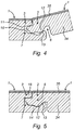
- the coupling parts 6-7 are constructed as a tongue 10 and a groove 11, which provide for the vertical locking and comprise locking parts 12-13, which, in the coupled condition, prevent the shifting apart of the tongue and groove.
- the groove 11 is limited by a lower lip 14 and an upper lip 15, and that the locking parts 12 and 13 are performed in the form of cooperating projections, at the lower side of the tongue 10 and at the upper side of the lower lip 14, respectively.
- the cooperation is performed by means of locking surfaces 16 and 17 provided for this purpose.
- the lower lip 14 extends laterally up to beyond the distal end of the upper lip 15, more particularly such that the locking surface 17 is situated entirely in that portion of the lower lip 14 which is situated beyond the upper lip 15. As schematically represented in FIGS.
- the coupling parts 8-9 at the second pair of opposite edges 4-5 are configured such that two of such panels 1 can be coupled to each other by means of a downward movement of one panel in respect to the other. This downward movement will be discussed more detailed below.
- the coupling parts 8-9 herein also form a first locking system, which effects a locking in the plane of the panels 1 and perpendicular to said edges 4-5, thus, in the case in the horizontal direction, as well as a second locking system, which effects a locking perpendicularly to the plane defined by the panels 1, in this case, thus, the vertical direction.
- the first locking system is substantially formed of an upwardly directed lower hook-shaped portion 18 situated at the edge 5, as well as of a downwardly directed upper hook-shaped portion 19 which is situated at the opposite edge 4, which hook-shaped portions can be engaged one behind the other by said downward movement.
- the lower hook-shaped portion 18 consists of a lip 20, which extends laterally from the lower edge of the panel 1 and which is provided with an upwardly directed locking element 21 with a locking surface 22, whereas the upper hook-shaped portion 19 consists of a lip 23, which extends laterally from the upper edge of the panel 1 and which is provided with a downwardly directed locking element 24 with a locking surface 25.
- the second locking system of the edges at the short sides is formed by locking parts 26-27, which are situated next to the proximal extremity 28 of the lower hook-shaped portion 18 and the distal extremity 29 of the upper hook-shaped portion 19, respectively.
- the locking parts 26-27 consist of projections engaging one behind the other, which define locking surfaces 30-31.
- the coupling parts 8-9 principally also may be considered a tongue and groove coupling, wherein the locking part 27 functions as a tongue, whereas the groove in which this tongue gets seated, is defined by the locking part 26 functioning as the upper lip, and the first hook-shaped portion 18 functioning as the lower lip.
- the panel 1 is substantially formed on the basis of magnesium oxide (MgO). More specifically, it comprises a core layer (substrate), which is realized on the basis magnesium oxide, commonly enriched with at least one binder, such as magnesium sulphate and/or magnesium chloride.
- the core layer is indicated by reference 34 in FIGS. 2-7 .
- this substrate is schematically depicted as a single layer. In reality, this may be a single layer as well as several layers, which not all have to comprise magnesium oxide.
- a top layer 35 is provided on the core layer 34, which in FIGS. 2-7 also is represented by a single layer, however, in reality also may consist of several layers, typically at least a decorative layer covered by at least one wear layer.
- the top layer 35 has at least the aim of providing a decorative upper side 36 at the panel 1, preferably in the form of a printed decor and, at least in the case of a floor panel, providing for offering a wear-resistant surface.
- the panels have a total thickness T.
- the thickness T preferably has a value situated between 3 and 10 mm. In particular in a practical embodiment, this value will be situated between 4 and 7 mm.
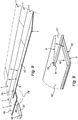
- FIGS. 8 and 9 it is schematically represented how the panels 1 can be installed.
- a number of the panels 1, in order to differentiate additionally, are indicated by references 1A, 1B, 1C.
- the panels 1 are laid down row per row and coupled to each other.
- the method comprises at least the following steps: installing a first panel 1A intended for forming part of a first row of panels; coupling a second panel 1B to said first panel 1A, such at first edges 2-3, wherein this second panel 1B is intended for forming part of a second row successive to said first row of panels; coupling in the second row a third panel 1C both to said second panel 1B as to the first panel 1A, wherein the third panel 1C is coupled to the first panel 1A by means of a turning movement, wherein the third panel 1C, from an upwardly pivoted position, is brought into substantially the same plane as the first and second panels, whereas, as a result of this movement and the downward movement created therein, the hook-shaped portions 18-19 engage into each other between the third and second panel.
- each form of movement in a very broad sense each form of movement is meant in which, in a cross-section as seen in FIGS. 6 and 7 , the one panel is let down from a higher position in relation to the other.
- This movement M does not necessarily have to be a rectilinear movement, and during this movement, temporary deformations in the panels and more particularly in the hook-shaped portions 18 and 19 may occur.
- a downward movement M which, seen in cross-section, is rectilinear or almost rectilinear, may be used for engaging a panel 1C into a panel 1B, which means that the right-hand panel in FIG. 6 , seen in cross-section, simply is pressed straight down into the position of FIG. 7 .
- the snap effect is obtained by (some) elasticity of the magnesium oxide based material of the core layer 34 and the bending actions in the component parts and compressions in the material occurring as a result thereof.
- FIG. 10 shows a detailed side view of an alternative floor panel 40 according to the invention, though which may be the same floor panel 1 as shown in FIGS. 1-9 .
- Floor panel 40 comprises a laminate of layers stacked onto each other, wherein said laminate comprises, from bottom to top, the following layers:
- the backing layer 41 may be composed of paper, in particular resin impregnated paper. Here, melamine resin-impregnated paper is preferably used. A backing layer 41 is helpful in providing an optimum interface between the panel and the underlying surface on which the panels are applied.
- the crust layers 42, 46 have a higher density compared to the density of the core layer 44, which provide rigidity to the floor panel 40. Moreover, this allows, in combination with the fibreglass meshes 43a,43b, 45, acting as reinforcement layers, sanding (sandblasting) of the crust layers 42, 46 during production.
- the crust layers 42, 46 and the core layer 44 comprise magnesium oxide, a binder, such as magnesium chloride and/or magnesium sulphate, and additives. A typical composition of the three layers is given below.
- the top layer 47 may consist of one or more layers, and may include a urea-aldehyde resin impregnated decorative paper layer, being attached, preferably by means of one or more glues, to the upper crust layer 46.
- a pair of opposite side edges of the floor panel 40 is provided with complementary coupling parts, in particular a male coupling part 48 and a complementary female coupling part 49, allowing panels to be interconnected, as discussed extensively above.
- the remaining edges (not shown) of the floor panel 40 may be provided with the same and/or an alternatively shaped set of coupling parts.
- the male coupling part 48 having the shape of a tongue, is composed of core material, and also includes the upper fibreglass mesh 45.
- a thinned (sanded) part of the upper crust layer 46 may also be included in the male coupling part 40.
- the female coupling part 49 constitutes a groove configured to accommodate a complementary tongue of an adjacent floor. Said groove is enclosed by an upper lip 49a formed by the upper crust layer 46 and the top layer 47, and a lower lip 49b formed by the core layer 44, both lower fibreglass meshes 43a, 43b and the backing layer 41.
- the lower part of the groove is formed within the core layer 44, at a distance from the lower fibreglass meshes 43a, 43b.
- the distance between the lower fibreglass meshes 43a, 43b may be zero, though it is also imaginable that the meshes 43a, 43b are positioned at a distance from each other, wherein material of the lower crust layer 42 is positioned in between both meshes 43a, 43b.
- FIGS. 11a-11c successive method steps for manufacturing the floor panel 40 as shown in FIG. 10 are shown.
- FIG. 11a a starting laminate with a originally, relatively thick upper crust layer 46 is shown.
- this upper crust layer 46 is applied as slurry (paste) on top of the upper mesh 45 positioned on top of the core layer 44.
- the thickness of the upper crust layer 46 is reduced by removing material from said upper crust layer 46 until a desired panel thickness is achieved ( FIG. 11b ).
- the top layer 47 is applied, preferably by gluing on top of the upper crust layer 46, resulting in the final floor panel 40 as shown in FIG. 10 .
- the lower crust layer 42 could be subjected to a sanding treatment (prior to applying the backing layer 41), which provides more flexibility and freedom in adjusting the panel thickness based upon a (uniform, and typically oversized) starting laminate.
- FIG. 12 shows a detailed side view of yet another floor panel 51 according to the invention, though which (also) may be the same floor panel 1 as shown in FIGS. 1-9 .
- Floor panel 51 comprises a laminate of layers stacked onto each other, wherein said laminate comprises, from bottom to top, the following layers:
- the PVC top layer 60 consists of a PVC decor layer covered by a PVC wear layer.
- the PVC sublayer 59 is preferably free of any plasticizer.
- the sublayer 59 is positioned between the core layer 56 and the top layer 60 in order to reach a desired effect such as sound improvement, indentation resistance improvement.
- the composition of the other layers 52-58 may be identical to the equivalent layers shown in FIG. 10 .
- the distance between both lower meshes 53, 55 is about 1 mm.
- a pair of opposite side edges of the floor panel 51 is provided with complementary coupling parts, in particular a male coupling part 61 and a complementary female coupling part 62, allowing panels to be interconnected, as discussed extensively above.
- the remaining edges (not shown) of the floor panel 51 may be provided with the same and/or an alternatively shaped set of coupling parts.
- the male coupling part 61 having the shape of a tongue, is composed of the core layer 56, the upper fibreglass mesh 57, and the upper crust layer 58.
- the female coupling part 62 constitutes a groove configured to accommodate a complementary tongue of an adjacent floor. Said groove is enclosed by an upper lip 62a formed by the upper crust layer PVC sublayer 59 and the top layer 60, and a lower lip 62b formed by the core layer 56, both lower fibreglass meshes 53, 55, and the first and second lower crust layers 52, 54.
- the lower part of the groove is formed within the core layer 44, at a distance from the lower fibreglass meshes 43a, 43b to secure sufficient rigidity and strength of the female coupling part 62.
- the floor panel 51 shown in FIG. 12 is waterproof, fire-resistant, and rigid.
- inventive concepts are illustrated by several illustrative embodiments. It is conceivable that individual inventive concepts may be applied without, in so doing, also applying other details of the described example. It is not necessary to elaborate on examples of all conceivable combinations of the above-described inventive concepts, as a person skilled in the art will understand numerous inventive concepts can be (re)combined in order to arrive at a specific application.
Abstract
Description
- The invention relates to a floor panel, in particular a magnesium oxide based floor panel, which is preferably provided with interconnecting coupling parts for mutually connecting adjacent floor panels to each other. The invention also relates to a method of producing a floor panel, in particular a magnesium oxide based floor panel.
- In the field of floor and wall coverings, panels are widely used based on wood materials or derivatives thereof, especially as a material for the main or core layer of the panel. An example is given in
US patent 6,688,061 . A major disadvantage is the hygroscopic nature of such materials, which affects the lifetime and durability of such panels. As an alternative several thermoplastic materials such as polyvinyl chloride is used, which while being water resistant, present other disadvantages. Polyvinyl chloride (PVC) that is used for panels such as in patentCN 100419019 , has a flexible quality which requires a perfectly smooth and even surface of the substrate on which the panel covering is applied. If such is not the case, any unevenness will be visible through the panel as it conforms with the underlying substrate surface, which is a detrimental effect from an aesthetic point of view to the user. Furthermore, the use of PVC as core material in a floor panel leads to floor panel which is susceptible to temperature changes in its ambient environment which will cause the vinyl flooring to expand and contract with normal hot and cold fluctuations. There is a general need in the field to develop a floor panel which while having waterproof properties, can be produced with a relatively uniform thickness leading to a relatively even (flat) upper surface. There is also a need in the field to develop a floor panel of which the thickness can be adjusted relatively easily during production, while maintaining sufficient strength of the panel. There is furthermore a need to develop a fireproof panel. - It is an objective of the invention to meet at least one of the needs addressed above.
- The above objective of the invention, is met by the provision of a panel, in particular a floor panel, according to the above preamble, comprising a laminate of: magnesium oxide based core layer, at least one magnesium oxide based upper crust layer positioned on top of said core layer, wherein the density of said upper crust layer is preferably larger than the density of the core layer, and at least one upper reinforcing layer situated in between said core layer and said at least one upper crust layer. The application of magnesium oxide (MgO) as material in the floor panel leads to significant less flammability compared to traditional wood based and/or PVC based floor panels, wherein the MgO based floor panel according to the invention may even be completely fire-resistant (inflammable). Moreover, the application of MgO in the core layer and the crust layer(s) makes the floor panel also waterproof. Additionally, the application of MgO in the core layer and crust layer(s) of the floor panel according to the invention leads to a floor panel which is less susceptible for temperature changes and is dimensionally stable during ambient temperature fluctuations. Another important advantage of the floor panel according to the invention is the application of a particular laminate of layers, wherein the relatively high-density upper crust layer is configured to be subjected to a sanding treatment (also referred to a sandblasting treatment, or to a dry abrasive blast cleaning process) in order to accurately and uniformly reduce the thickness of said crust layer, and hence the thickness of the floor panel as such. Hence, during production of floor panels with different desired panel thicknesses (e.g. 6, 8, and 10 mm), one may take the abovementioned (uniform) laminate of layers as (uniform) starting point, after which the upper crust layer is sanded to such an extent that the desired panel thickness is achieved. The presence of at least one upper reinforcement layer improves the panel strength, and allows the upper crust layer to be sanded. Moreover, the upper reinforcement layer also provides additional panel strength during use of the panels. The relatively low-density core layer is less compact than the crust layer and therefore relatively light-weighted, which reduces the total weight of the floor panel. Experiments have shown that it is in particular advantageous in case the density of each crust layer is between 8% and 12% larger, in particular about 10% larger, than the density of the core layer. The density of the core layer is preferably situated between 1000 and 1800 kg/m3, preferably between 1100 and 1500 kg/m3, more preferably between 1200 and 1400 kg/m3. The density of the upper crust layer is preferably between 1100 and 2000 kg/m3, preferably between 1400 and 1800 kg/m3, more preferably between 1500 and 1600 kg/m3. Primarily, the invention relates to floor panels, more particularly decorative floor panels for forming a floor covering, however, it is not excluded to apply the panels according to the invention with other forms of coverings, for example, as wall panels, ceiling panels and the like.
- The floor panel according to the invention may be a glue down floor panel. However, it is also imaginable, and often advantageous, in case the floor panel, in particular the core layer, comprises a first pair of opposite edges, said first pair of opposite edges comprising complementary coupling parts allowing to mutually couple of plurality of floor panels to each other. This allows the panels according to the invention to be installed floatingly. More preferably, the coupling parts at said first pair of edges form a first locking system which effects a locking in a plane defined by the floor panel and perpendicular to the respective edges, as well as form a second locking system which effects a locking perpendicular to said plane defined by the floor panels. This dual locking effect, both in horizontal and vertical direction, improves the mutual locking of adjacent floor panels. Preferably the floor panel, in particular the core layer, comprises a second pair of opposite edges, wherein both pairs of opposite edges comprise coupling parts allowing to mutually couple a plurality of floor panels to each other. More preferably, the coupling parts at the first pair of opposite edges are configured such that two of such panels can be coupled to each other at these edges by means of a turning movement, and the coupling parts at the second pair of opposite edges are configured such that two of such floor panels can be coupled to each other by means of a downward movement of one panel in respect to the other, more particularly by means of the downward movement obtained as a result of the turning movement at the first pair of edges. The second locking system at the second pair of edges may consist of locking parts engaging behind each other, which can be brought one behind the other by their elasticity and/or movability. By also integrating the coupling parts at the second pair of sides into the core layer, great properties are commonly obtained for realizing a coupling which allows a locking by means of a downward movement. It should be clear that these panels can be installed floatingly, which, however, does not exclude that, according to an alternative, they can be glued to the underlying surface, as well.
- In addition to the presence of the magnesium oxide in the core layer and the upper crust layer, preferably the core layer and/or the upper crust layer(s) comprises magnesium sulphate and/or magnesium chloride. Both magnesium sulphate and magnesium chloride act as binder (binding agent). In the context of the invention, magnesium oxide and a suitable binder (e.g. magnesium sulphate and/or magnesium chloride) preferably have a combined content in the total mineral material of about 60 to 90 wt.%. Further, the weight ratio between magnesium oxide and a suitable binder, is in the range of 4:1 to 2:1, and preferably about 3:1. Since magnesium sulphate absorbs significant less water compared to magnesium chloride, it is commonly preferred to apply magnesium sulphate as (primary) binder, which secures sufficient rigidity of the floor panel, also in relatively humid environments. This preference does, however, not exclude the presence of magnesium chloride in the core layer.
- In a preferred embodiment the core layer and/or the upper crust layer(s) comprises wood fibres. The presence of wood fibres commonly improves the processability of these layers, which will facilitate the production of the floor panel as such. Moreover, the presence of wood fibres in the upper crust layer allows a decorative paper layer to be durable glued on top of said upper crust layer. Both wood and paper are cellulose based, allowing a relatively firm and durable attachment to each other. To this end, it is advantageous in case the upper crust layer comprises at least 10 wt.% wood, and more preferably between 40 and 50 wt. % wood. The weight content of wood fibres in the core layer is preferably larger than the weight content of wood fibres in the upper crust layer. This allows the upper crust layer(s) to obtain an increased density compared to the density of the core layer, which is favourable for sanding the upper crust layer. Instead of, or in addition to, also other kind of natural fibres, in particular cellulose fibres, such as bamboo fibres or straw fibres, can be applied in the core layer and/or the upper crust layer(s).
- Preferably, both the core layer and the upper crust layer comprise water, wherein the weight content of water in the core layer is more preferably larger than the weight content of water in the upper crust layer. This allows contributes to the increase of the density of the upper crust layer(s) compared to the density of the core layer. Here, it is noted that magnesium oxide will react with water resulting in magnesium hydroxide (MgO + H2O → Mg(OH)2). Moreover, also magnesium sulphate, if applied, may be hydrated by the presence of water, predominantly resulting in magnesium sulphate heptahydrate.
- The presence of the at least one upper reinforcement layer leads to significant improvement of the floor panels as such, which is favourable both during production (in particular sanding) and during use of the floor panels. Moreover, the reinforcement layer commonly leads to improvement of the acoustic (sound-dampening) properties of the tiles. The reinforcement layer may comprise a woven or non-woven fibre material, for example a fibreglass material. They may have a thickness of 0, 2 - 0,4 mm. Preferably the upper reinforcing layer comprises a fiberglass mesh. The fiberglass mesh preferably has a mesh size of at least 5x5 mm, and more preferably (about) 7x7 mm. The fiberglass mesh preferably has an area weight of at least 90 g/m2 to provide sufficient strength to the floor panel. The application of a low alkaline fiberglass mesh is preferred in order to ensure a long lasting strength. Since, fibres of fibreglass may lead to itching of the human skin during use/(de)installation of the floor panels, the fiberglass mesh is preferably provided with a coating. This makes the fibres, in particular the fibre ends less sharp for the human skin. The same applies in case separate (loose) fibres of fibreglass are used as reinforcement layer. Suitable coatings are e.g. a wax, a resin, or another type of coating.
- In a preferred embodiment the laminate of the floor panel according to the invention further comprises: at least one magnesium oxide based lower crust layer positioned underneath the core layer, wherein the density of said at least one lower crust layer is preferably larger than the density of the core layer; and at least one lower reinforcing layer situated in between said core layer and said at least one lower crust layer. The application of at least one lower crust layer and at least one lower reinforcing layer situated in between the lower crust layer and the core layer, not only allows the floor panel according to the invention additional strength, but also allows the lower crust layer to be sanded, and hence to be reduced in thickness during production. This means that the floor panel can be sanded both at the top surface and at the bottom surface of the floor panel during production (either simultaneously and/or successively), which allows to control the thickness of the upper crust layer, the thickness of the lower crust layer, and consequently to control the panel thickness as such. It is advantageous in case the laminate comprises a plurality of lower reinforcing layers, preferably two lower reinforcing layers, stacked on top of each other. The application of two (or more) lower reinforcing layers commonly significantly improves the panel strength. Here, it is commonly beneficial in case the laminate comprises a plurality of lower crust layers, wherein at least one lower crust layer is positioned in between at least two lower reinforcing layers, and wherein at least one lower crust layer is positioned underneath a lowest, lower reinforcing layer. The thickness of the intermediate lower crust layer enclosed by both lower reinforcement layers is commonly small, typically about 1 mm or less. The density of the lower crust layer is preferably between 1100 and 2000 kg/m3, preferably between 1400 and 1800 kg/m3, more preferably between 1500 and 1600 kg/m3. The composition of the lower crust layer may be identical to the composition of the upper crust layer, expect for the fact that the lower crust layer may be free of wood fibres. This improves the (desired) rigidity of the lower crust layers. The lower reinforcement layer(s) may have an identical composition compared to the upper reinforcement layer(s), and is preferably (also) formed by an, optionally at least partially coated, fiberglass mesh. A backing layer may be applied to the underside of the (lowest) lower crust layer. It is imaginable that, in case the laminate comprises (i) at least one magnesium oxide based lower crust layer positioned underneath the core layer, wherein the density of said at least one lower crust layer is preferably larger than the density of the core layer; and (ii) at least one lower reinforcing layer situated in between said core layer and said at least one lower crust layer, that the upper crust layer(s) may be omitted, and optionally the upper reinforcing layer(s) may also be omitted.
- On top of the upper crust layer, a top structure is commonly attached, preferably by means of gluing, wherein said top structure comprises a decorative layer and a wear layer covering said decorative layer. The decorative layer is composed of a film provided and/or printed with a motif. The decorative layer may be a paper layer and/or a polymer layer, such as a PVC layer. The wear layer is commonly substantially transparent. The wear layer may consist of one or more transparent lacquer layers. The wear layer may consist of a thin layer of vinyl (PVC), in which wear-resistant particles, preferably ceramic particles, such as corundum and the like, are incorporated. Instead of applying a polymer decorative layer, the laminate may also comprise a urea-formaldehyde (resin) impregnated, decorative paper layer, attached, preferably glued, to the upper crust layer. The advantage of this latter embodiment is that the urea-formaldehyde also acts a relatively scratch-resistant wear layer. Moreover, the paper layer can be glued relatively firmly and durable to the upper crust layer, in particular in case the upper crust layer is provided with wood fibres as mentioned above. Typically, the thickness of the top structure in the panel of the invention is in the range of 0.2 to 2.0 mm.
- The invention also relates to a method of producing a floor panel according to one of the foregoing claims, comprising the steps of:
- A) providing a laminate of:
- ∘ a magnesium oxide based core layer;
- ∘ at least one magnesium oxide based upper crust layer positioned on top of said core layer, wherein the density of said upper crust layer is larger than the density of the core layer; and
- ∘ at least one upper reinforcing layer situated in between said core layer and said at least one upper crust layer; and
- B) reducing the thickness of at least one upper crust layer by subjecting said upper crust layer to a sanding treatment.
- at least one magnesium oxide based lower crust layer positioned underneath the core layer, wherein the density of said at least one lower crust layer is larger than the density of the core layer; and
- at least one lower reinforcing layer situated in between said core layer and said at least one lower crust layer;
- The invention further relates to a covering, in particular a floor covering, comprising a plurality of interconnected panels according to any of the preceding claims.
- The invention will be elucidated on the basis of non-limitative exemplary embodiments shown in the following figures. Herein:
-
FIG. 1 in top plan view represents a panel, more particularly a floor panel, according to the invention; -
FIGS. 2 and 3 , at a larger scale, represent cross-sections according to the lines II-II and inFIG. 1 ; -
FIGS. 4 and 5 represent how the panels can be interconnected at their long sides; -
FIGS. 6 and 7 represent how the panels fit into each other at their short sides; -
FIG. 8 represents how a plurality of panels fromFIG. 1 can be connected to each other; -
FIG. 9 , at a larger scale, represents the portion indicated by F9 inFIG. 8 ; -
FIG. 10 represents a detailed side view of an alternative floor panel according to the invention; -
FIGS. 11a-11c represent successive process steps for manufacturing the panel shown inFIG. 10 ; and -
Figure 12 represents a detailed side view of yet another floor panel according to the invention. - In the represented example shown in
FIGS. 1-7 , thepanel 1 is made as an oblong rectangular strip and thus comprises a first pair of opposite edges 2-3, which in this case form the long sides of thepanel 1, and a second pair of opposite edges 4-5, which form the short sides of thepanel 1. Typically, thefloor panel 1 has a width in the range of 100 to 600 mm and a length in the range of 300 to 2500 mm. As is represented more in detail inFIGS. 2 and 3 , both pairs of opposite edges 2-3 and 4-5 comprise coupling parts 6-7, 8-9, respectively, which allow to mutually couple a plurality ofsuch panels 1 to each other. As specifically represented in theFIGS. 4 and 5 , coupling parts 6-7 at the first pair of opposite edges 2-3 are configured such that two of such panels can be coupled to each other at these edges 2-3 in a locking manner by means of a turning movement. Herein, the coupling parts 6-7 form a first locking system which effects a locking in the plane of thepanels 1 and perpendicularly to said edges 2-3, thus, in this case in the horizontal direction, as well as form a second locking system, which effects a locking perpendicularly to the plane of thepanels 1, in this case, thus, in the vertical direction. To this aim, the coupling parts 6-7 are constructed as atongue 10 and agroove 11, which provide for the vertical locking and comprise locking parts 12-13, which, in the coupled condition, prevent the shifting apart of the tongue and groove. Herein, it is preferred that, as indicated, thegroove 11 is limited by alower lip 14 and anupper lip 15, and that the lockingparts tongue 10 and at the upper side of thelower lip 14, respectively. The cooperation is performed by means of lockingsurfaces lower lip 14 extends laterally up to beyond the distal end of theupper lip 15, more particularly such that the lockingsurface 17 is situated entirely in that portion of thelower lip 14 which is situated beyond theupper lip 15. As schematically represented inFIGS. 6 and 7 , the coupling parts 8-9 at the second pair of opposite edges 4-5 are configured such that two ofsuch panels 1 can be coupled to each other by means of a downward movement of one panel in respect to the other. This downward movement will be discussed more detailed below. As is clearly visible inFIG. 7 , the coupling parts 8-9 herein also form a first locking system, which effects a locking in the plane of thepanels 1 and perpendicular to said edges 4-5, thus, in the case in the horizontal direction, as well as a second locking system, which effects a locking perpendicularly to the plane defined by thepanels 1, in this case, thus, the vertical direction. The first locking system is substantially formed of an upwardly directed lower hook-shapedportion 18 situated at theedge 5, as well as of a downwardly directed upper hook-shapedportion 19 which is situated at theopposite edge 4, which hook-shaped portions can be engaged one behind the other by said downward movement. The lower hook-shapedportion 18 consists of alip 20, which extends laterally from the lower edge of thepanel 1 and which is provided with an upwardly directed lockingelement 21 with a lockingsurface 22, whereas the upper hook-shapedportion 19 consists of alip 23, which extends laterally from the upper edge of thepanel 1 and which is provided with a downwardly directed lockingelement 24 with a lockingsurface 25. The second locking system of the edges at the short sides is formed by locking parts 26-27, which are situated next to theproximal extremity 28 of the lower hook-shapedportion 18 and thedistal extremity 29 of the upper hook-shapedportion 19, respectively. The locking parts 26-27 consist of projections engaging one behind the other, which define locking surfaces 30-31. It is noted that the coupling parts 8-9 principally also may be considered a tongue and groove coupling, wherein the lockingpart 27 functions as a tongue, whereas the groove in which this tongue gets seated, is defined by the lockingpart 26 functioning as the upper lip, and the first hook-shapedportion 18 functioning as the lower lip. It is noted that the space between the vertically active lockingpart 26 and the horizontally active lockingelement 21, which is also indicated by opening H, functions as afemale part 32, whereas the lockingelement 24 is made as amale part 33, which fits into thefemale part 32. Thepanel 1 is substantially formed on the basis of magnesium oxide (MgO). More specifically, it comprises a core layer (substrate), which is realized on the basis magnesium oxide, commonly enriched with at least one binder, such as magnesium sulphate and/or magnesium chloride. The core layer is indicated byreference 34 inFIGS. 2-7 . In these figures, this substrate is schematically depicted as a single layer. In reality, this may be a single layer as well as several layers, which not all have to comprise magnesium oxide. Usually, atop layer 35 is provided on thecore layer 34, which inFIGS. 2-7 also is represented by a single layer, however, in reality also may consist of several layers, typically at least a decorative layer covered by at least one wear layer. Thetop layer 35 has at least the aim of providing a decorativeupper side 36 at thepanel 1, preferably in the form of a printed decor and, at least in the case of a floor panel, providing for offering a wear-resistant surface. As indicated inFIG. 7 , the panels have a total thickness T. The thickness T preferably has a value situated between 3 and 10 mm. In particular in a practical embodiment, this value will be situated between 4 and 7 mm. - In
FIGS. 8 and 9 , it is schematically represented how thepanels 1 can be installed. In order to explain the method, a number of thepanels 1, in order to differentiate additionally, are indicated byreferences panels 1 are laid down row per row and coupled to each other. In order to obtain that the panels are coupled at the edges 2-3 as well as 4-5, the method comprises at least the following steps: installing afirst panel 1A intended for forming part of a first row of panels; coupling asecond panel 1B to saidfirst panel 1A, such at first edges 2-3, wherein thissecond panel 1B is intended for forming part of a second row successive to said first row of panels; coupling in the second row athird panel 1C both to saidsecond panel 1B as to thefirst panel 1A, wherein thethird panel 1C is coupled to thefirst panel 1A by means of a turning movement, wherein thethird panel 1C, from an upwardly pivoted position, is brought into substantially the same plane as the first and second panels, whereas, as a result of this movement and the downward movement created therein, the hook-shaped portions 18-19 engage into each other between the third and second panel. It is clear that normally, between installing thefirst panel 1A and coupling thesecond panel 1B thereto, first also all further panels of the row in which thefirst panel 1A is situated, are installed. Coupling thesecond panel 1B to thefirst panel 1A also is performed by connecting thepanel 1B at itsedge 2, by means of a turning movement as represented inFIG. 4 , to theedge 3 of thefirst panel 1A and possible other panels of the row of thepanel 1A. When connecting thepanel 1C to thepanel 1A, also a turning movement, as inFIG. 4 , is applied. Herein, a downward movement M is performed at the short edges 4-5, by which thecoupling parts FIGS. 6 and 7 , the one panel is let down from a higher position in relation to the other. This movement M does not necessarily have to be a rectilinear movement, and during this movement, temporary deformations in the panels and more particularly in the hook-shapedportions panel 1C into apanel 1B, which means that the right-hand panel inFIG. 6 , seen in cross-section, simply is pressed straight down into the position ofFIG. 7 . It is clear that herein effectively small local deformations will occur, as the lockingparts core layer 34 and the bending actions in the component parts and compressions in the material occurring as a result thereof. -
FIG. 10 shows a detailed side view of analternative floor panel 40 according to the invention, though which may be thesame floor panel 1 as shown inFIGS. 1-9 .Floor panel 40 comprises a laminate of layers stacked onto each other, wherein said laminate comprises, from bottom to top, the following layers: - a
backing layer 41, - a
lower crust layer 42, - two lower fibreglass meshes 43a, 43b,
- a
core layer 44, - an
upper fibreglass mesh 45, - an
upper crust layer 46, and - a
top layer 47 and/ortop structure 47. - The
backing layer 41 may be composed of paper, in particular resin impregnated paper. Here, melamine resin-impregnated paper is preferably used. Abacking layer 41 is helpful in providing an optimum interface between the panel and the underlying surface on which the panels are applied. The crust layers 42, 46 have a higher density compared to the density of thecore layer 44, which provide rigidity to thefloor panel 40. Moreover, this allows, in combination with the fibreglass meshes 43a,43b, 45, acting as reinforcement layers, sanding (sandblasting) of the crust layers 42, 46 during production. The crust layers 42, 46 and thecore layer 44 comprise magnesium oxide, a binder, such as magnesium chloride and/or magnesium sulphate, and additives. A typical composition of the three layers is given below.Layer Material Ratio Upper crust layer 46Magnesium Oxide 13.4% Magnesium sulphate heptahydrate 5.4% Water 6.0% Modifier aluminium sulphate 0.1% Fly ash 4.7% Wood fibres 1.1 % Core layer 44 Magnesium Oxide 13.4% Magnesium sulphate heptahydrate 5.4% Water 10.7% Modifier aluminium sulphate 0.1% Fly ash 4.7% Wood fibres 4.7% Lower crust layer 42Magnesium Oxide 13.4% Magnesium sulphate heptahydrate 5.4% Water 6.7% Modifier aluminium sulphate 0.1% Fly ash 4.7% - The
top layer 47 may consist of one or more layers, and may include a urea-aldehyde resin impregnated decorative paper layer, being attached, preferably by means of one or more glues, to theupper crust layer 46. As shown inFIG. 10 a pair of opposite side edges of thefloor panel 40 is provided with complementary coupling parts, in particular amale coupling part 48 and a complementaryfemale coupling part 49, allowing panels to be interconnected, as discussed extensively above. The remaining edges (not shown) of thefloor panel 40 may be provided with the same and/or an alternatively shaped set of coupling parts. Themale coupling part 48, having the shape of a tongue, is composed of core material, and also includes theupper fibreglass mesh 45. Optionally, a thinned (sanded) part of theupper crust layer 46 may also be included in themale coupling part 40. Thefemale coupling part 49 constitutes a groove configured to accommodate a complementary tongue of an adjacent floor. Said groove is enclosed by an upper lip 49a formed by theupper crust layer 46 and thetop layer 47, and a lower lip 49b formed by thecore layer 44, both lower fibreglass meshes 43a, 43b and thebacking layer 41. The lower part of the groove is formed within thecore layer 44, at a distance from the lower fibreglass meshes 43a, 43b. The distance between the lower fibreglass meshes 43a, 43b may be zero, though it is also imaginable that the meshes 43a, 43b are positioned at a distance from each other, wherein material of thelower crust layer 42 is positioned in between both meshes 43a, 43b. - In
FIGS. 11a-11c successive method steps for manufacturing thefloor panel 40 as shown inFIG. 10 are shown. InFIG. 11a a starting laminate with a originally, relatively thickupper crust layer 46 is shown. Typically thisupper crust layer 46 is applied as slurry (paste) on top of theupper mesh 45 positioned on top of thecore layer 44. By means of known high-precision sandblasting equipment 50, the thickness of theupper crust layer 46 is reduced by removing material from saidupper crust layer 46 until a desired panel thickness is achieved (FIG. 11b ). Subsequently, shown inFIG. 11c thetop layer 47 is applied, preferably by gluing on top of theupper crust layer 46, resulting in thefinal floor panel 40 as shown inFIG. 10 . Optionally, also thelower crust layer 42 could be subjected to a sanding treatment (prior to applying the backing layer 41), which provides more flexibility and freedom in adjusting the panel thickness based upon a (uniform, and typically oversized) starting laminate. -
FIG. 12 shows a detailed side view of yet anotherfloor panel 51 according to the invention, though which (also) may be thesame floor panel 1 as shown inFIGS. 1-9 .Floor panel 51 comprises a laminate of layers stacked onto each other, wherein said laminate comprises, from bottom to top, the following layers: - a first
lower crust layer 52, - a first
lower fibreglass mesh 53 - a second
lower crust layer 54, - a second
lower fibreglass mesh 55, - a
core layer 56, - an
upper fibreglass mesh 57, - an
upper crust layer 58, - a
PVC sublayer 59, and - a
PVC top layer 60 ortop structure 60. - In this embodiment, the
PVC top layer 60 consists of a PVC decor layer covered by a PVC wear layer. ThePVC sublayer 59 is preferably free of any plasticizer. Thesublayer 59 is positioned between thecore layer 56 and thetop layer 60 in order to reach a desired effect such as sound improvement, indentation resistance improvement. The composition of the other layers 52-58 may be identical to the equivalent layers shown inFIG. 10 . The distance between bothlower meshes FIG. 12 a pair of opposite side edges of thefloor panel 51 is provided with complementary coupling parts, in particular amale coupling part 61 and a complementaryfemale coupling part 62, allowing panels to be interconnected, as discussed extensively above. The remaining edges (not shown) of thefloor panel 51 may be provided with the same and/or an alternatively shaped set of coupling parts. Themale coupling part 61, having the shape of a tongue, is composed of thecore layer 56, theupper fibreglass mesh 57, and theupper crust layer 58. Thefemale coupling part 62 constitutes a groove configured to accommodate a complementary tongue of an adjacent floor. Said groove is enclosed by an upper lip 62a formed by the upper crustlayer PVC sublayer 59 and thetop layer 60, and a lower lip 62b formed by thecore layer 56, both lower fibreglass meshes 53, 55, and the first and second lower crust layers 52, 54. The lower part of the groove is formed within thecore layer 44, at a distance from the lower fibreglass meshes 43a, 43b to secure sufficient rigidity and strength of thefemale coupling part 62. Thefloor panel 51 shown inFIG. 12 is waterproof, fire-resistant, and rigid. - It will be apparent that the invention is not limited to the working examples shown and described herein, but that numerous variants are possible within the scope of the attached claims that will be obvious to a person skilled in the art.
- The above-described inventive concepts are illustrated by several illustrative embodiments. It is conceivable that individual inventive concepts may be applied without, in so doing, also applying other details of the described example. It is not necessary to elaborate on examples of all conceivable combinations of the above-described inventive concepts, as a person skilled in the art will understand numerous inventive concepts can be (re)combined in order to arrive at a specific application.
- The verb "comprise" and conjugations thereof used in this patent publication are understood to mean not only "comprise", but are also understood to mean the phrases "contain", "substantially consist of", "formed by" and conjugations thereof.
Claims (14)
- Floor panel (1, 40, 51), wherein the panel (1) is made as an oblong rectangular strip, comprising a first pair of opposite edges (2-3) and a second pair of opposite edges (4-5), both pairs of opposite edges (2-3; 4-5) comprise coupling parts (6-7; 8-9), which allow to mutually couple a plurality of such panels (1) to each other,- wherein said coupling parts (6-7) at the first pair of opposite edges (2-3) are configured such that two of such panels can be coupled to each other at these edges (2-3) in a locking manner by means of a turning movement, wherein the coupling parts (6-7) form a first locking system which effects a locking in a horizontal direction in the plane of the panels (1) and perpendicularly to said edges (2-3), as well as form a second locking system, which effects a locking in a vertical direction perpendicularly to the plane of the panels (1), wherein the coupling parts (6-7) are constructed as a tongue (10) and a groove (11), which provide for the vertical locking and comprise locking parts (12-13), which, in the coupled condition, prevent the shifting apart of the tongue and groove,- wherein said coupling parts (8-9) at the second pair of opposite edges (4-5) are configured such that two of such panels (1) can be coupled to each other by means of a downward movement of one panel in respect to the other, wherein the coupling parts (8-9) herein also form a first locking system, which effects a locking in a horizontal direction in the plane of the panels (1) and perpendicular to said edges (4-5), as well as a second locking system, which effects a locking in a vertical direction perpendicularly to the plane defined by the panels (1), wherein said first locking system is substantially formed of an upwardly directed lower hook-shaped portion (18) situated at a first edge (5) of said second pair of opposite edges (4-5), as well as of a downwardly directed upper hook-shaped portion (19) which is situated at a second edge (4) of said second pair of opposite edges (4-5), which hook-shaped portions can be engaged one behind the other by said downward movement,characterized in that said panel (1) comprises a substrate of mineral material, which is realized on the basis of magnesium oxide and at least one binder, said binder being magnesium sulphate and/or magnesium chloride.
- Floor panel according to any of the preceding claims, characterized in that said mineral material further comprises wood or other cellulose fibers.
- Floor panel according to claim 1 or 2, characterized in that said substrate is a single layer.
- Floor panel according to claim 1 or 2, characterized in that said substrate comprises several layers, wherein at least one of said several layers comprises magnesium oxide.
- Floor panel according to claim 4, characterized in that said substrate comprises a laminate of:- a magnesium oxide based core layer (34, 44, 56);- at least one magnesium oxide based upper crust layer (35, 46, 58) positioned on top of said core layer (34, 44, 56) and at least one upper reinforcing layer situated in between said core layer (34, 44, 56) and said at least one upper crust layer (35, 46, 58).
- Floor panel according to claim 5, characterized in that said reinforcement layer comprises a fiberglass mesh (45, 57).
- Floor panel according to any of the preceding claims, characterized in that said top layer is provided on said substrate, wherein said top layer comprises at least a decorative layer covered by a wear layer.
- Floor panel according to claim 7, characterized in that said decorative layer is a paper layer and/or a polymer layer, and said wear layer is substantially transparent.
- Floor panel according to any of the preceding claims, characterized in that said magnesium oxide and binder have a combined content in the total mineral material of about 60 to 90 wt.%, the weight ratio between magnesium oxide and said binder being in the range of 4:1 to 2:1, and preferably about 3:1.
- Floor panel according to any of the preceding claims, characterized in that said first pair of opposite side edges (2-3) forms the long sides, and said second pair of opposite side edges forms the short sides of said panel (1).
- Floor panel according to any of the preceding claims, characterized in that said groove (11) is limited by a lower lip (14) and an upper lip (15), and that the locking parts (12-13) are performed in the form of cooperating projections, at the lower side of the tongue (10) and at the upper side of the lower lip (14), respectively, wherein said cooperation is performed by means of locking surfaces (16) and (17).
- Floor panel according to claim 11, characterized in that said lower lip (14) extends laterally up to beyond the distal end of the upper lip (15), such that the locking surface (17) is situated entirely in that portion of the lower lip (14) which is situated beyond the upper lip (15).
- Floor panel according to any of the preceding claims, characterized in that said lower hook-shaped portion (18) consists of a lip (20), which extends laterally from the lower edge of the panel (1) and which is provided with an upwardly directed locking element (21) with a locking surface (22), whereas the upper hook-shaped portion (19) consists of a lip (23), which extends laterally from the upper edge of the panel (1) and which is provided with a downwardly directed locking element (24) with a locking surface (25), wherein said second locking system of the second pair of opposite edges is formed by locking parts (26-27) consisting of projections engaging one behind the other, which define locking surfaces (30-31).
- Floor panel according to any of the preceding claims, characterized in that in said engagement of said hook-shaped portions (18-19) one behind the other a snap-effect is obtained by the elasticity of said magnesium oxide based mineral material.
Applications Claiming Priority (4)
| Application Number | Priority Date | Filing Date | Title |
|---|---|---|---|
| NL2019108A NL2019108B1 (en) | 2017-06-22 | 2017-06-22 | Floor panel and method of producing such a floor panel |
| EP18739467.1A EP3494267B1 (en) | 2017-06-22 | 2018-06-22 | Floor panel and method of producing such a floor panel |
| EP19185528.7A EP3584388B1 (en) | 2017-06-22 | 2018-06-22 | Floor panel and method of producing such a floor panel |
| PCT/EP2018/066809 WO2018234561A1 (en) | 2017-06-22 | 2018-06-22 | Floor panel and method of producing such a floor panel |
Related Parent Applications (2)
| Application Number | Title | Priority Date | Filing Date |
|---|---|---|---|
| EP18739467.1A Division EP3494267B1 (en) | 2017-06-22 | 2018-06-22 | Floor panel and method of producing such a floor panel |
| EP19185528.7A Division EP3584388B1 (en) | 2017-06-22 | 2018-06-22 | Floor panel and method of producing such a floor panel |
Publications (2)
| Publication Number | Publication Date |
|---|---|
| EP3845721A1 true EP3845721A1 (en) | 2021-07-07 |
| EP3845721B1 EP3845721B1 (en) | 2022-08-31 |
Family
ID=59746323
Family Applications (3)
| Application Number | Title | Priority Date | Filing Date |
|---|---|---|---|
| EP18739467.1A Active EP3494267B1 (en) | 2017-06-22 | 2018-06-22 | Floor panel and method of producing such a floor panel |
| EP19185528.7A Active EP3584388B1 (en) | 2017-06-22 | 2018-06-22 | Floor panel and method of producing such a floor panel |
| EP21153494.6A Active EP3845721B1 (en) | 2017-06-22 | 2018-06-22 | Floor panel and method of producing such a floor panel |
Family Applications Before (2)
| Application Number | Title | Priority Date | Filing Date |
|---|---|---|---|
| EP18739467.1A Active EP3494267B1 (en) | 2017-06-22 | 2018-06-22 | Floor panel and method of producing such a floor panel |
| EP19185528.7A Active EP3584388B1 (en) | 2017-06-22 | 2018-06-22 | Floor panel and method of producing such a floor panel |
Country Status (14)
| Country | Link |
|---|---|
| US (1) | US20200123788A1 (en) |
| EP (3) | EP3494267B1 (en) |
| JP (1) | JP2020524759A (en) |
| KR (2) | KR20230133411A (en) |
| CN (1) | CN110770405A (en) |
| AU (1) | AU2018287258B8 (en) |
| CA (1) | CA3067663A1 (en) |
| EA (1) | EA038825B1 (en) |
| ES (2) | ES2930211T3 (en) |
| MX (1) | MX2019015542A (en) |
| NL (1) | NL2019108B1 (en) |
| PL (1) | PL3494267T3 (en) |
| WO (1) | WO2018234561A1 (en) |
| ZA (1) | ZA201908354B (en) |
Families Citing this family (28)
| Publication number | Priority date | Publication date | Assignee | Title |
|---|---|---|---|---|
| WO2018130729A1 (en) * | 2017-01-12 | 2018-07-19 | Euro Trade Flooring, S.L. | Plate for covering horizontal and vertical surfaces |
| NL2021885B1 (en) * | 2018-10-26 | 2020-05-13 | I4F Licensing Nv | Multi-purpose tile system, tile covering, and tile |
| NL2022114B1 (en) * | 2018-12-03 | 2020-06-30 | I4F Licensing Nv | Decorative panel, and decorative floor covering consisting of said panels |
| NL2022369B9 (en) * | 2019-01-10 | 2020-09-17 | Champion Link Int Corp | Panel suitable for assembling a floor covering |
| EP3947849A4 (en) * | 2019-03-25 | 2022-12-07 | Ceraloc Innovation AB | A mineral-based panel comprising grooves and a method for forming grooves |
| DE102019117426A1 (en) * | 2019-06-27 | 2020-12-31 | Guido Schulte | Plate-shaped component |
| DE102019117425A1 (en) * | 2019-06-27 | 2020-12-31 | Guido Schulte | Plate-shaped component and method for its manufacture |
| US20210129566A1 (en) * | 2019-10-30 | 2021-05-06 | Yuuma Usui | Printed matter producing method, printed matter producing apparatus, and printed matter |
| NL2024630B1 (en) * | 2020-01-09 | 2021-09-07 | I4F Licensing Nv | Glue-down decorative floor covering system |
| US11718565B2 (en) | 2020-01-31 | 2023-08-08 | Champion Link International Corporation | Panel for forming a floor covering and such floor covering |
| US11391049B2 (en) * | 2020-01-31 | 2022-07-19 | Champion Link International Corporation | Panel and method of producing such a panel |
| US11927020B2 (en) | 2020-01-31 | 2024-03-12 | Champion Link International Corporation | Floor panel and method of manufacturing a floor panel |
| NL2024805B1 (en) * | 2020-01-31 | 2021-09-13 | Champion Link Int Corp | Panel for forming a floor covering and such floor covering |
| NL2024806B1 (en) * | 2020-01-31 | 2021-09-13 | Champion Link Int Corp | Panel and method of producing such a panel |
| US11097512B1 (en) | 2020-01-31 | 2021-08-24 | Champion Link Intern Aiton Al Corporation | Floor panel and method of manufacturing a floor panel |
| NL2024807B1 (en) * | 2020-01-31 | 2021-09-13 | Champion Link Int Corp | Floor panel and method of manufacturing of a floor panel |
| US11149441B2 (en) | 2020-03-13 | 2021-10-19 | Champion Link International Corporation | Panel and method of producing a panel |
| US11542712B2 (en) | 2020-03-13 | 2023-01-03 | Champion Link International Corporation | Panel and method of producing a panel |
| US11724537B2 (en) | 2020-05-26 | 2023-08-15 | Champion Link International Corporation | Panel and method for producing a panel |
| NL2025684B1 (en) * | 2020-05-26 | 2021-12-14 | Champion Link Int Corp | Panel and method for producing a panel |
| US20210387436A1 (en) * | 2020-06-12 | 2021-12-16 | Välinge Innovation AB | Building panel comprising mineral-based layer |
| WO2021251893A1 (en) * | 2020-06-12 | 2021-12-16 | Välinge Innovation AB | A building panel comprising mineral-based layer |
| US11326356B2 (en) | 2020-07-15 | 2022-05-10 | Champion Link International Corporation | Floor or wall panel |
| US11530536B2 (en) | 2020-07-15 | 2022-12-20 | Champion Link International Corporation | Panel |
| EP3971364A1 (en) * | 2020-09-17 | 2022-03-23 | Surface Technologies GmbH & Co. KG | Panel |
| EP3971365A1 (en) * | 2020-09-17 | 2022-03-23 | Surface Technologies GmbH & Co. KG | Panel |
| CA3194073A1 (en) | 2020-09-30 | 2022-04-07 | Scott Johnson | Fire-rated structural osb panels with overlaid water-resistant barrier |
| FR3121948A1 (en) * | 2021-04-19 | 2022-10-21 | Les 27 Cles De Saint Pierre | Parquet strip comprising a removable interlocking assembly system |
Citations (6)
| Publication number | Priority date | Publication date | Assignee | Title |
|---|---|---|---|---|
| WO2000063510A1 (en) * | 1999-04-20 | 2000-10-26 | Patt S.R.L. | Floor covering consisting of floor panels and method for the assembly thereof |
| US6688061B2 (en) | 1999-11-05 | 2004-02-10 | Industrias Auxiliares Faus, S.L. | Direct laminated floor |
| CN100419019C (en) | 2006-07-15 | 2008-09-17 | 庄广盛 | Wear-resistant wood plastic floor and its production technology |
| EP2060389A1 (en) * | 2007-11-14 | 2009-05-20 | Van Cauwenberge NV | Laminate panels for flooring, wall and ceiling systems |
| DE102013113478A1 (en) * | 2013-12-04 | 2015-06-11 | Guido Schulte | Floor, wall or ceiling panel and method of making the same |
| EP3031998A1 (en) * | 2014-12-08 | 2016-06-15 | Akzenta Paneele + Profile GmbH | Panel with a hook-like locking system |
Family Cites Families (27)
| Publication number | Priority date | Publication date | Assignee | Title |
|---|---|---|---|---|
| DE2810180C2 (en) * | 1978-03-09 | 1985-02-14 | Bayer Ag, 5090 Leverkusen | Process for the production of a fire-protecting, foamed material as well as coatings, insulation, cable insulation, insulation protection layers, plates, molded bodies and other objects formed therefrom on the basis of magnesia cement |
| US4724187A (en) * | 1986-03-25 | 1988-02-09 | Nevamar Corporation | Conductive laminate flooring |
| JP2582283B2 (en) * | 1988-06-13 | 1997-02-19 | エスケ−化研株式会社 | Building material made of phosphoric acid cured product |
| US5073425A (en) * | 1988-10-07 | 1991-12-17 | Armstrong World Industries, Inc. | Polyvinyl chloride surface covering compositions having reduced electrical resistivities |
| WO1999016984A1 (en) * | 1997-09-26 | 1999-04-08 | Ibiden Co., Ltd. | Composite refractory building material, method of manufacturing the same, gypsum board, and resin composition |
| WO2000049246A1 (en) * | 1999-02-16 | 2000-08-24 | Ibiden Co., Ltd. | Composite building material and production method thereof and comosite floor material |
| DE10330298A1 (en) * | 2003-07-04 | 2005-02-03 | Kronotec Ag | Panel, in particular floor laminate panel |
| CN2642917Y (en) * | 2003-09-28 | 2004-09-22 | 付志洪 | Composite floor made from fiberglass and magnesian compound and plant fiber |
| CN100389941C (en) * | 2006-07-07 | 2008-05-28 | 杨光伟 | Multilayer flame-retardant composite wood and method for producing same |
| KR20080042995A (en) * | 2006-11-13 | 2008-05-16 | 주식회사 엘지화학 | Flooring having surface layer treated with inorganic paint |
| DE102007019179A1 (en) * | 2007-04-20 | 2008-10-30 | Center For Abrasives And Refractories Research & Development C.A.R.R.D. Gmbh | Wear protection layer |
| KR20110045402A (en) * | 2009-10-26 | 2011-05-04 | 성낙현 | Functional loess flooring and manufacturing method thereof |
| CN101761213A (en) * | 2009-12-30 | 2010-06-30 | 德华兔宝宝装饰新材股份有限公司 | Antiflaming floor and manufacture method thereof |
| CN201907139U (en) * | 2010-08-09 | 2011-07-27 | 庄启程 | Novel low-carbon plywood |
| CN202265980U (en) * | 2010-08-09 | 2012-06-06 | 庄启程 | Novel low-carbon floor board |
| CN101941218A (en) * | 2010-08-09 | 2011-01-12 | 庄启程 | Novel low-carbon veneer and manufacture method thereof |
| CN101922225A (en) * | 2010-08-18 | 2010-12-22 | 金奉基 | Laminate plate floor and preparation method thereof |
| BE1020134A5 (en) * | 2011-08-30 | 2013-05-07 | Aldinvest Nv | METHOD FOR PROVIDING A STONE VIEW OF A WEAR STRUCTURE |
| BE1022209B1 (en) * | 2012-01-12 | 2016-03-01 | I.V.C. N.V. | FLOOR PANEL |
| EP2664730A1 (en) * | 2012-05-15 | 2013-11-20 | Falquon GmbH | Panel for laying in an area as cladding or lining with improved moisture resistance |
| BE1020722A3 (en) * | 2012-06-01 | 2014-04-01 | Unilin Bvba | PANEL FOR FORMING A FLOOR COVERING AND METHOD FOR MANUFACTURING SUCH PANELS. |
| JP2014066078A (en) * | 2012-09-26 | 2014-04-17 | Tatsuya Tahara | Building composite material, and construction method thereof |
| WO2015051419A1 (en) * | 2013-10-10 | 2015-04-16 | Australian Fireboard Company Pty Ltd | Composite board comprising magnesium oxide and magnesium chloride |
| US10293571B2 (en) * | 2014-05-20 | 2019-05-21 | Euro Trade Flooring, S.L. | Multilayer lining plate for horizontal support |
| CN104131680B (en) * | 2014-07-18 | 2016-08-17 | 张家港市盛港新型建材科技有限公司 | The special floor of magnesium container house and manufacture method thereof |
| CN105133807A (en) * | 2015-08-20 | 2015-12-09 | 广州市美彩数码制品有限公司 | Wall panel |
| CN106121187A (en) * | 2016-07-04 | 2016-11-16 | 常州布鲁板业科技有限公司 | Sanding floor panel structure and formula thereof and processing technique |
-
2017
- 2017-06-22 NL NL2019108A patent/NL2019108B1/en active
-
2018
- 2018-06-22 EA EA202090110A patent/EA038825B1/en unknown
- 2018-06-22 AU AU2018287258A patent/AU2018287258B8/en active Active
- 2018-06-22 WO PCT/EP2018/066809 patent/WO2018234561A1/en unknown
- 2018-06-22 US US16/624,509 patent/US20200123788A1/en active Pending
- 2018-06-22 CA CA3067663A patent/CA3067663A1/en active Pending
- 2018-06-22 PL PL18739467T patent/PL3494267T3/en unknown
- 2018-06-22 ES ES21153494T patent/ES2930211T3/en active Active
- 2018-06-22 KR KR1020237030911A patent/KR20230133411A/en active Application Filing
- 2018-06-22 MX MX2019015542A patent/MX2019015542A/en unknown
- 2018-06-22 JP JP2020520719A patent/JP2020524759A/en active Pending
- 2018-06-22 EP EP18739467.1A patent/EP3494267B1/en active Active
- 2018-06-22 EP EP19185528.7A patent/EP3584388B1/en active Active
- 2018-06-22 EP EP21153494.6A patent/EP3845721B1/en active Active
- 2018-06-22 CN CN201880003808.1A patent/CN110770405A/en active Pending
- 2018-06-22 KR KR1020207001356A patent/KR20200039660A/en active Application Filing
- 2018-06-22 ES ES18739467T patent/ES2773724T3/en active Active
-
2019
- 2019-12-13 ZA ZA2019/08354A patent/ZA201908354B/en unknown
Patent Citations (6)
| Publication number | Priority date | Publication date | Assignee | Title |
|---|---|---|---|---|
| WO2000063510A1 (en) * | 1999-04-20 | 2000-10-26 | Patt S.R.L. | Floor covering consisting of floor panels and method for the assembly thereof |
| US6688061B2 (en) | 1999-11-05 | 2004-02-10 | Industrias Auxiliares Faus, S.L. | Direct laminated floor |
| CN100419019C (en) | 2006-07-15 | 2008-09-17 | 庄广盛 | Wear-resistant wood plastic floor and its production technology |
| EP2060389A1 (en) * | 2007-11-14 | 2009-05-20 | Van Cauwenberge NV | Laminate panels for flooring, wall and ceiling systems |
| DE102013113478A1 (en) * | 2013-12-04 | 2015-06-11 | Guido Schulte | Floor, wall or ceiling panel and method of making the same |
| EP3031998A1 (en) * | 2014-12-08 | 2016-06-15 | Akzenta Paneele + Profile GmbH | Panel with a hook-like locking system |
Also Published As
| Publication number | Publication date |
|---|---|
| EP3494267A1 (en) | 2019-06-12 |
| JP2020524759A (en) | 2020-08-20 |
| MX2019015542A (en) | 2021-03-02 |
| NL2019108B1 (en) | 2019-01-07 |
| US20200123788A1 (en) | 2020-04-23 |
| EP3584388A1 (en) | 2019-12-25 |
| EA038825B1 (en) | 2021-10-25 |
| EP3584388B1 (en) | 2021-01-27 |
| AU2018287258A1 (en) | 2020-02-06 |
| EP3845721B1 (en) | 2022-08-31 |
| WO2018234561A1 (en) | 2018-12-27 |
| CA3067663A1 (en) | 2018-12-27 |
| ES2773724T3 (en) | 2020-07-14 |
| EA202090110A1 (en) | 2020-04-08 |
| EP3494267B1 (en) | 2019-11-20 |
| AU2018287258A8 (en) | 2023-02-02 |
| PL3494267T3 (en) | 2020-11-02 |
| CN110770405A (en) | 2020-02-07 |
| KR20200039660A (en) | 2020-04-16 |
| ZA201908354B (en) | 2022-03-30 |
| KR20230133411A (en) | 2023-09-19 |
| ES2930211T3 (en) | 2022-12-07 |
| BR112019027505A2 (en) | 2020-12-29 |
| AU2018287258B2 (en) | 2022-12-22 |
| AU2018287258B8 (en) | 2023-02-02 |
Similar Documents
| Publication | Publication Date | Title |
|---|---|---|
| EP3584388B1 (en) | Floor panel and method of producing such a floor panel | |
| EP2957691B1 (en) | Panel suitable for assembling a waterproof floor or wall covering, method of producing a panel | |
| KR20140074218A (en) | Cover layer with outside film layer of an elastic plastic | |
| EP2971391B1 (en) | Gypsum-panel for acoustical monolithic ceiling | |
| US20240102246A1 (en) | Board, method for manufacturing a board and a panel comprising such board material | |
| EP3192939B1 (en) | Skirting board, decorative system and method for manufacturing a skirting board | |
| US20230330980A1 (en) | Composite panels and methods for making the same | |
| JP2006007713A (en) | Wooden composite decorative plate and its manufacturing method | |
| CN113374205A (en) | Decorative plate mounting structure and construction method | |
| EP0884152A1 (en) | A slab of stone material with multiple layer paper and phenolic resin-based backing, and method for making slab | |
| CN204662833U (en) | A kind of imitative graining panel and decorative panel thereof | |
| BR112019027505B1 (en) | FLOOR PANEL AND METHOD OF PRODUCING A FLOOR PANEL | |
| CN217949599U (en) | Wave-shaped sound-absorbing rubber-plastic decorative composite board | |
| US8850777B2 (en) | Wall board with edge strip and method for production thereof | |
| WO2021152152A1 (en) | Panel and method of producing such a panel | |
| CN211597527U (en) | Multi-layer solid wood composite floor | |
| CN2353825Y (en) | Fine-wood decorative plate with curled tongue-and-groove | |
| CN204662832U (en) | A kind of imitative iron rust decoration panel and decorative panel thereof | |
| JP2003253807A (en) | Spandrel wall panel and method of constructing the same | |
| JP2001020492A (en) | Grooved decoration board and manufacture of the board |
Legal Events
| Date | Code | Title | Description |
|---|---|---|---|
| PUAI | Public reference made under article 153(3) epc to a published international application that has entered the european phase |
Free format text: ORIGINAL CODE: 0009012 |
|
| STAA | Information on the status of an ep patent application or granted ep patent |
Free format text: STATUS: THE APPLICATION HAS BEEN PUBLISHED |
|
| AC | Divisional application: reference to earlier application |
Ref document number: 3584388 Country of ref document: EP Kind code of ref document: P Ref document number: 3494267 Country of ref document: EP Kind code of ref document: P |
|
| AK | Designated contracting states |
Kind code of ref document: A1 Designated state(s): AL AT BE BG CH CY CZ DE DK EE ES FI FR GB GR HR HU IE IS IT LI LT LU LV MC MK MT NL NO PL PT RO RS SE SI SK SM TR |
|
| STAA | Information on the status of an ep patent application or granted ep patent |
Free format text: STATUS: REQUEST FOR EXAMINATION WAS MADE |
|
| 17P | Request for examination filed |
Effective date: 20220107 |
|
| RBV | Designated contracting states (corrected) |
Designated state(s): AL AT BE BG CH CY CZ DE DK EE ES FI FR GB GR HR HU IE IS IT LI LT LU LV MC MK MT NL NO PL PT RO RS SE SI SK SM TR |
|
| GRAP | Despatch of communication of intention to grant a patent |
Free format text: ORIGINAL CODE: EPIDOSNIGR1 |
|
| STAA | Information on the status of an ep patent application or granted ep patent |
Free format text: STATUS: GRANT OF PATENT IS INTENDED |
|
| RIC1 | Information provided on ipc code assigned before grant |
Ipc: E04F 15/02 20060101ALN20220211BHEP Ipc: E04F 15/10 20060101ALN20220211BHEP Ipc: B32B 13/00 20060101ALN20220211BHEP Ipc: E04F 15/00 20060101AFI20220211BHEP |
|
| INTG | Intention to grant announced |
Effective date: 20220316 |
|
| GRAS | Grant fee paid |
Free format text: ORIGINAL CODE: EPIDOSNIGR3 |
|
| GRAA | (expected) grant |
Free format text: ORIGINAL CODE: 0009210 |
|
| STAA | Information on the status of an ep patent application or granted ep patent |
Free format text: STATUS: THE PATENT HAS BEEN GRANTED |
|
| AC | Divisional application: reference to earlier application |
Ref document number: 3494267 Country of ref document: EP Kind code of ref document: P Ref document number: 3584388 Country of ref document: EP Kind code of ref document: P |
|
| AK | Designated contracting states |
Kind code of ref document: B1 Designated state(s): AL AT BE BG CH CY CZ DE DK EE ES FI FR GB GR HR HU IE IS IT LI LT LU LV MC MK MT NL NO PL PT RO RS SE SI SK SM TR |
|
| REG | Reference to a national code |
Ref country code: CH Ref legal event code: EP Ref country code: GB Ref legal event code: FG4D |
|
| REG | Reference to a national code |
Ref country code: AT Ref legal event code: REF Ref document number: 1515386 Country of ref document: AT Kind code of ref document: T Effective date: 20220915 Ref country code: DE Ref legal event code: R096 Ref document number: 602018040207 Country of ref document: DE |
|
| REG | Reference to a national code |
Ref country code: IE Ref legal event code: FG4D |
|
| REG | Reference to a national code |
Ref country code: NL Ref legal event code: FP |
|
| REG | Reference to a national code |
Ref country code: ES Ref legal event code: FG2A Ref document number: 2930211 Country of ref document: ES Kind code of ref document: T3 Effective date: 20221207 |
|
| REG | Reference to a national code |
Ref country code: LT Ref legal event code: MG9D |
|
| PG25 | Lapsed in a contracting state [announced via postgrant information from national office to epo] |
Ref country code: SE Free format text: LAPSE BECAUSE OF FAILURE TO SUBMIT A TRANSLATION OF THE DESCRIPTION OR TO PAY THE FEE WITHIN THE PRESCRIBED TIME-LIMIT Effective date: 20220831 Ref country code: RS Free format text: LAPSE BECAUSE OF FAILURE TO SUBMIT A TRANSLATION OF THE DESCRIPTION OR TO PAY THE FEE WITHIN THE PRESCRIBED TIME-LIMIT Effective date: 20220831 Ref country code: NO Free format text: LAPSE BECAUSE OF FAILURE TO SUBMIT A TRANSLATION OF THE DESCRIPTION OR TO PAY THE FEE WITHIN THE PRESCRIBED TIME-LIMIT Effective date: 20221130 Ref country code: LV Free format text: LAPSE BECAUSE OF FAILURE TO SUBMIT A TRANSLATION OF THE DESCRIPTION OR TO PAY THE FEE WITHIN THE PRESCRIBED TIME-LIMIT Effective date: 20220831 Ref country code: LT Free format text: LAPSE BECAUSE OF FAILURE TO SUBMIT A TRANSLATION OF THE DESCRIPTION OR TO PAY THE FEE WITHIN THE PRESCRIBED TIME-LIMIT Effective date: 20220831 Ref country code: FI Free format text: LAPSE BECAUSE OF FAILURE TO SUBMIT A TRANSLATION OF THE DESCRIPTION OR TO PAY THE FEE WITHIN THE PRESCRIBED TIME-LIMIT Effective date: 20220831 |
|
| REG | Reference to a national code |
Ref country code: AT Ref legal event code: MK05 Ref document number: 1515386 Country of ref document: AT Kind code of ref document: T Effective date: 20220831 |
|
| PG25 | Lapsed in a contracting state [announced via postgrant information from national office to epo] |
Ref country code: PL Free format text: LAPSE BECAUSE OF FAILURE TO SUBMIT A TRANSLATION OF THE DESCRIPTION OR TO PAY THE FEE WITHIN THE PRESCRIBED TIME-LIMIT Effective date: 20220831 Ref country code: IS Free format text: LAPSE BECAUSE OF FAILURE TO SUBMIT A TRANSLATION OF THE DESCRIPTION OR TO PAY THE FEE WITHIN THE PRESCRIBED TIME-LIMIT Effective date: 20221231 Ref country code: HR Free format text: LAPSE BECAUSE OF FAILURE TO SUBMIT A TRANSLATION OF THE DESCRIPTION OR TO PAY THE FEE WITHIN THE PRESCRIBED TIME-LIMIT Effective date: 20220831 Ref country code: GR Free format text: LAPSE BECAUSE OF FAILURE TO SUBMIT A TRANSLATION OF THE DESCRIPTION OR TO PAY THE FEE WITHIN THE PRESCRIBED TIME-LIMIT Effective date: 20221201 |
|
| PG25 | Lapsed in a contracting state [announced via postgrant information from national office to epo] |
Ref country code: SM Free format text: LAPSE BECAUSE OF FAILURE TO SUBMIT A TRANSLATION OF THE DESCRIPTION OR TO PAY THE FEE WITHIN THE PRESCRIBED TIME-LIMIT Effective date: 20220831 Ref country code: RO Free format text: LAPSE BECAUSE OF FAILURE TO SUBMIT A TRANSLATION OF THE DESCRIPTION OR TO PAY THE FEE WITHIN THE PRESCRIBED TIME-LIMIT Effective date: 20220831 Ref country code: PT Free format text: LAPSE BECAUSE OF FAILURE TO SUBMIT A TRANSLATION OF THE DESCRIPTION OR TO PAY THE FEE WITHIN THE PRESCRIBED TIME-LIMIT Effective date: 20230102 Ref country code: DK Free format text: LAPSE BECAUSE OF FAILURE TO SUBMIT A TRANSLATION OF THE DESCRIPTION OR TO PAY THE FEE WITHIN THE PRESCRIBED TIME-LIMIT Effective date: 20220831 Ref country code: CZ Free format text: LAPSE BECAUSE OF FAILURE TO SUBMIT A TRANSLATION OF THE DESCRIPTION OR TO PAY THE FEE WITHIN THE PRESCRIBED TIME-LIMIT Effective date: 20220831 Ref country code: AT Free format text: LAPSE BECAUSE OF FAILURE TO SUBMIT A TRANSLATION OF THE DESCRIPTION OR TO PAY THE FEE WITHIN THE PRESCRIBED TIME-LIMIT Effective date: 20220831 |
|
| PG25 | Lapsed in a contracting state [announced via postgrant information from national office to epo] |
Ref country code: SK Free format text: LAPSE BECAUSE OF FAILURE TO SUBMIT A TRANSLATION OF THE DESCRIPTION OR TO PAY THE FEE WITHIN THE PRESCRIBED TIME-LIMIT Effective date: 20220831 Ref country code: EE Free format text: LAPSE BECAUSE OF FAILURE TO SUBMIT A TRANSLATION OF THE DESCRIPTION OR TO PAY THE FEE WITHIN THE PRESCRIBED TIME-LIMIT Effective date: 20220831 |
|
| REG | Reference to a national code |
Ref country code: DE Ref legal event code: R097 Ref document number: 602018040207 Country of ref document: DE |
|
| P01 | Opt-out of the competence of the unified patent court (upc) registered |
Effective date: 20230517 |
|
| PG25 | Lapsed in a contracting state [announced via postgrant information from national office to epo] |
Ref country code: AL Free format text: LAPSE BECAUSE OF FAILURE TO SUBMIT A TRANSLATION OF THE DESCRIPTION OR TO PAY THE FEE WITHIN THE PRESCRIBED TIME-LIMIT Effective date: 20220831 |
|
| PLBE | No opposition filed within time limit |
Free format text: ORIGINAL CODE: 0009261 |
|
| STAA | Information on the status of an ep patent application or granted ep patent |
Free format text: STATUS: NO OPPOSITION FILED WITHIN TIME LIMIT |
|
| PGFP | Annual fee paid to national office [announced via postgrant information from national office to epo] |
Ref country code: NL Payment date: 20230626 Year of fee payment: 6 Ref country code: FR Payment date: 20230626 Year of fee payment: 6 Ref country code: DE Payment date: 20230626 Year of fee payment: 6 |
|
| 26N | No opposition filed |
Effective date: 20230601 |
|
| PG25 | Lapsed in a contracting state [announced via postgrant information from national office to epo] |
Ref country code: SI Free format text: LAPSE BECAUSE OF FAILURE TO SUBMIT A TRANSLATION OF THE DESCRIPTION OR TO PAY THE FEE WITHIN THE PRESCRIBED TIME-LIMIT Effective date: 20220831 |
|
| PGFP | Annual fee paid to national office [announced via postgrant information from national office to epo] |
Ref country code: BE Payment date: 20230627 Year of fee payment: 6 |
|
| PGFP | Annual fee paid to national office [announced via postgrant information from national office to epo] |
Ref country code: GB Payment date: 20230627 Year of fee payment: 6 Ref country code: ES Payment date: 20230703 Year of fee payment: 6 |
|
| PG25 | Lapsed in a contracting state [announced via postgrant information from national office to epo] |
Ref country code: MC Free format text: LAPSE BECAUSE OF FAILURE TO SUBMIT A TRANSLATION OF THE DESCRIPTION OR TO PAY THE FEE WITHIN THE PRESCRIBED TIME-LIMIT Effective date: 20220831 |
|
| PG25 | Lapsed in a contracting state [announced via postgrant information from national office to epo] |
Ref country code: MC Free format text: LAPSE BECAUSE OF FAILURE TO SUBMIT A TRANSLATION OF THE DESCRIPTION OR TO PAY THE FEE WITHIN THE PRESCRIBED TIME-LIMIT Effective date: 20220831 |
|
| REG | Reference to a national code |
Ref country code: CH Ref legal event code: PL |
|
| PG25 | Lapsed in a contracting state [announced via postgrant information from national office to epo] |
Ref country code: LU Free format text: LAPSE BECAUSE OF NON-PAYMENT OF DUE FEES Effective date: 20230622 |
|
| REG | Reference to a national code |
Ref country code: IE Ref legal event code: MM4A |
|
| PG25 | Lapsed in a contracting state [announced via postgrant information from national office to epo] |
Ref country code: LU Free format text: LAPSE BECAUSE OF NON-PAYMENT OF DUE FEES Effective date: 20230622 |
|
| PG25 | Lapsed in a contracting state [announced via postgrant information from national office to epo] |
Ref country code: IE Free format text: LAPSE BECAUSE OF NON-PAYMENT OF DUE FEES Effective date: 20230622 |