EP3843944B1 - Riemenspannvorrichtung für materialabtragungsmaschinen - Google Patents
Riemenspannvorrichtung für materialabtragungsmaschinen Download PDFInfo
- Publication number
- EP3843944B1 EP3843944B1 EP19769291.6A EP19769291A EP3843944B1 EP 3843944 B1 EP3843944 B1 EP 3843944B1 EP 19769291 A EP19769291 A EP 19769291A EP 3843944 B1 EP3843944 B1 EP 3843944B1
- Authority
- EP
- European Patent Office
- Prior art keywords
- spindle
- hub
- pulley
- material removal
- actuator
- Prior art date
- Legal status (The legal status is an assumption and is not a legal conclusion. Google has not performed a legal analysis and makes no representation as to the accuracy of the status listed.)
- Active
Links
Images




Classifications
-
- B—PERFORMING OPERATIONS; TRANSPORTING
- B23—MACHINE TOOLS; METAL-WORKING NOT OTHERWISE PROVIDED FOR
- B23D—PLANING; SLOTTING; SHEARING; BROACHING; SAWING; FILING; SCRAPING; LIKE OPERATIONS FOR WORKING METAL BY REMOVING MATERIAL, NOT OTHERWISE PROVIDED FOR
- B23D47/00—Sawing machines or sawing devices working with circular saw blades, characterised only by constructional features of particular parts
- B23D47/12—Sawing machines or sawing devices working with circular saw blades, characterised only by constructional features of particular parts of drives for circular saw blades
-
- B—PERFORMING OPERATIONS; TRANSPORTING
- B23—MACHINE TOOLS; METAL-WORKING NOT OTHERWISE PROVIDED FOR
- B23Q—DETAILS, COMPONENTS, OR ACCESSORIES FOR MACHINE TOOLS, e.g. ARRANGEMENTS FOR COPYING OR CONTROLLING; MACHINE TOOLS IN GENERAL CHARACTERISED BY THE CONSTRUCTION OF PARTICULAR DETAILS OR COMPONENTS; COMBINATIONS OR ASSOCIATIONS OF METAL-WORKING MACHINES, NOT DIRECTED TO A PARTICULAR RESULT
- B23Q5/00—Driving or feeding mechanisms; Control arrangements therefor
- B23Q5/02—Driving main working members
- B23Q5/04—Driving main working members rotary shafts, e.g. working-spindles
- B23Q5/043—Accessories for spindle drives
-
- B—PERFORMING OPERATIONS; TRANSPORTING
- B24—GRINDING; POLISHING
- B24B—MACHINES, DEVICES, OR PROCESSES FOR GRINDING OR POLISHING; DRESSING OR CONDITIONING OF ABRADING SURFACES; FEEDING OF GRINDING, POLISHING, OR LAPPING AGENTS
- B24B21/00—Machines or devices using grinding or polishing belts; Accessories therefor
- B24B21/18—Accessories
- B24B21/20—Accessories for controlling or adjusting the tracking or the tension of the grinding belt
-
- B—PERFORMING OPERATIONS; TRANSPORTING
- B24—GRINDING; POLISHING
- B24B—MACHINES, DEVICES, OR PROCESSES FOR GRINDING OR POLISHING; DRESSING OR CONDITIONING OF ABRADING SURFACES; FEEDING OF GRINDING, POLISHING, OR LAPPING AGENTS
- B24B27/00—Other grinding machines or devices
- B24B27/06—Grinders for cutting-off
-
- B—PERFORMING OPERATIONS; TRANSPORTING
- B24—GRINDING; POLISHING
- B24B—MACHINES, DEVICES, OR PROCESSES FOR GRINDING OR POLISHING; DRESSING OR CONDITIONING OF ABRADING SURFACES; FEEDING OF GRINDING, POLISHING, OR LAPPING AGENTS
- B24B47/00—Drives or gearings; Equipment therefor
- B24B47/10—Drives or gearings; Equipment therefor for rotating or reciprocating working-spindles carrying grinding wheels or workpieces
- B24B47/12—Drives or gearings; Equipment therefor for rotating or reciprocating working-spindles carrying grinding wheels or workpieces by mechanical gearing or electric power
-
- B—PERFORMING OPERATIONS; TRANSPORTING
- B24—GRINDING; POLISHING
- B24B—MACHINES, DEVICES, OR PROCESSES FOR GRINDING OR POLISHING; DRESSING OR CONDITIONING OF ABRADING SURFACES; FEEDING OF GRINDING, POLISHING, OR LAPPING AGENTS
- B24B47/00—Drives or gearings; Equipment therefor
- B24B47/26—Accessories, e.g. stops
-
- F—MECHANICAL ENGINEERING; LIGHTING; HEATING; WEAPONS; BLASTING
- F16—ENGINEERING ELEMENTS AND UNITS; GENERAL MEASURES FOR PRODUCING AND MAINTAINING EFFECTIVE FUNCTIONING OF MACHINES OR INSTALLATIONS; THERMAL INSULATION IN GENERAL
- F16H—GEARING
- F16H7/00—Gearings for conveying rotary motion by endless flexible members
- F16H7/08—Means for varying tension of belts, ropes or chains
-
- F—MECHANICAL ENGINEERING; LIGHTING; HEATING; WEAPONS; BLASTING
- F16—ENGINEERING ELEMENTS AND UNITS; GENERAL MEASURES FOR PRODUCING AND MAINTAINING EFFECTIVE FUNCTIONING OF MACHINES OR INSTALLATIONS; THERMAL INSULATION IN GENERAL
- F16H—GEARING
- F16H7/00—Gearings for conveying rotary motion by endless flexible members
- F16H7/08—Means for varying tension of belts, ropes or chains
- F16H7/10—Means for varying tension of belts, ropes or chains by adjusting the axis of a pulley
- F16H7/12—Means for varying tension of belts, ropes or chains by adjusting the axis of a pulley of an idle pulley
-
- F—MECHANICAL ENGINEERING; LIGHTING; HEATING; WEAPONS; BLASTING
- F16—ENGINEERING ELEMENTS AND UNITS; GENERAL MEASURES FOR PRODUCING AND MAINTAINING EFFECTIVE FUNCTIONING OF MACHINES OR INSTALLATIONS; THERMAL INSULATION IN GENERAL
- F16H—GEARING
- F16H7/00—Gearings for conveying rotary motion by endless flexible members
- F16H7/08—Means for varying tension of belts, ropes or chains
- F16H7/10—Means for varying tension of belts, ropes or chains by adjusting the axis of a pulley
- F16H7/14—Means for varying tension of belts, ropes or chains by adjusting the axis of a pulley of a driving or driven pulley
-
- B—PERFORMING OPERATIONS; TRANSPORTING
- B23—MACHINE TOOLS; METAL-WORKING NOT OTHERWISE PROVIDED FOR
- B23D—PLANING; SLOTTING; SHEARING; BROACHING; SAWING; FILING; SCRAPING; LIKE OPERATIONS FOR WORKING METAL BY REMOVING MATERIAL, NOT OTHERWISE PROVIDED FOR
- B23D45/00—Sawing machines or sawing devices with circular saw blades or with friction saw discs
- B23D45/16—Hand-held sawing devices with circular saw blades
-
- B—PERFORMING OPERATIONS; TRANSPORTING
- B27—WORKING OR PRESERVING WOOD OR SIMILAR MATERIAL; NAILING OR STAPLING MACHINES IN GENERAL
- B27B—SAWS FOR WOOD OR SIMILAR MATERIAL; COMPONENTS OR ACCESSORIES THEREFOR
- B27B5/00—Sawing machines working with circular or cylindrical saw blades; Components or equipment therefor
- B27B5/29—Details; Component parts; Accessories
- B27B5/30—Details; Component parts; Accessories for mounting or securing saw blades or saw spindles
-
- F—MECHANICAL ENGINEERING; LIGHTING; HEATING; WEAPONS; BLASTING
- F16—ENGINEERING ELEMENTS AND UNITS; GENERAL MEASURES FOR PRODUCING AND MAINTAINING EFFECTIVE FUNCTIONING OF MACHINES OR INSTALLATIONS; THERMAL INSULATION IN GENERAL
- F16H—GEARING
- F16H7/00—Gearings for conveying rotary motion by endless flexible members
- F16H7/24—Equipment for mounting belts, ropes, or chains
Definitions
- the present disclosure generally relates to belt tensioning apparatus and, more particularly, to belt tensioning apparatus for material removal machines.
- belt tensioner devices positioned along a length of a belt.
- the belt tensioner devices are conventionally configured to impinge upon a belt to adjust tension in the belt.
- these belt tensioner devices are imprecise and provide a limited range of potential belt tensions.
- the belt tensioner devices may constitute obstructions when attaching and/or removing the belt due to the placement of the belt tensioner devices near the belt.
- a material removal apparatus comprising a spindle configured to retain a material removal tool, a spindle pulley secured to the spindle, the spindle pulley configured to actuate the spindle and a hub having a body retaining the spindle such that an outer diameter of the body is less than the inner diameter of the spindle housing, the hub configured to change a position of the spindle pulley, the apparatus further comprising a hub lock configured to prohibit movement of the hub when engaged, and allow movement of the hub when disengaged.
- the present disclosure is directed to belt tensioning apparatus for material removal machines as set forth in the claims.
- the examples described herein are not limited to only the recited values, ranges of values, positions, orientations, and/or actions but rather should include reasonably workable deviations.
- x and/or y means any element of the three-element set ⁇ (x), (y), (x, y) ⁇ . In other words, “x and/or y” means “one or both of x and y”.
- x, y, and/or z means any element of the seven-element set ⁇ (x), (y), (z), (x, y), (x, z), (y, z), (x, y, z) ⁇ . In other words, "x, y and/or z” means “one or more of x, y and z”.
- Some examples of the present disclosure relate to a material removal apparatus, comprising a spindle configured to retain a material removal tool, a spindle pulley secured to the spindle, the spindle pulley configured to actuate the spindle, and a hub retaining the spindle, the hub configured to change a position of the spindle pulley.
- the apparatus further comprises an actuator pulley configured actuate the spindle pulley via a belt, the hub configured to change the position of the spindle pulley relative to the actuator pulley.
- the hub is configured to move the spindle pulley from a first position at a first distance from an actuator pulley, to a second position at a second distance from the actuator pulley, the first distance being different from the second distance.
- the belt has a first tension when the spindle pulley is at the first position, and a second tension when the spindle pulley is at the second position, the first tension being different from the second tension.
- the apparatus further comprises an actuator configured to actuate the actuator pulley.
- the hub is configured to change the position of the spindle pulley by changing the position of the spindle.
- the hub is configured to engage a hub moving tool.
- the apparatus further comprises a hub lock configured to prohibit movement of the hub when engaged, and allow movement of the hub when disengaged.
- the hub lock is secured to a spindle housing that encircles at least a portion of the hub and the spindle. In some examples, the hub lock is configured to compress the spindle housing when engaged.
- Some examples of the present disclosure relate to a method of adjusting belt tension in a material removal machine, comprising adjusting a position of a spindle pulley of the material removal machine via a hub of the material removal machine, wherein the spindle pulley is configured to actuate a material removal tool of the material removal machine.
- adjusting the position of the spindle pulley comprises adjusting the position of the spindle pulley with respect to an actuator pulley of the material removal machine. In some examples, adjusting the position of the spindle pulley comprises moving the spindle pulley from a first position at a first distance from an actuator pulley, to a second position at a second distance from the actuator pulley, the first distance being different from the second distance. In some examples, a belt connecting the spindle pulley to the actuator pulley has a first tension when the spindle pulley is at the first position, and a second tension when the spindle pulley is at the second position, the first tension being different from the second tension.
- the method further comprises actuating the material removal tool via the spindle pulley. In some examples, actuating the material removal tool via the spindle pulley comprises translating actuation of the actuator pulley into actuation of the spindle pulley through the belt connecting the actuator pulley and the spindle pulley. In some examples, the method further comprises gaining access to a hub lock of the material removal machine and unlocking the hub via the hub lock before adjusting the position of the spindle pulley. In some examples, the method further comprises gaining access to a hub lock of the material removal machine and locking the hub via the hub lock after adjusting the position of the spindle pulley.
- the spindle pulley is secured to a spindle of the material removal machine, the material removal tool is retained on the spindle, and the spindle is retained by the hub.
- adjusting the position of a spindle pulley via the hub comprises adjusting the hub using a tool that engages with engagement features of the hub.
- the material removal machine includes a material removal tool (e.g., a saw blade, an abrasive saw, a polisher, a grinder, and/or more general material preparation and/or testing tool).
- the material removal tool is mounted on a spindle that is actuated (e.g., turned, spun, etc.) by a spindle pulley, which is in turn actuated by an actuator pulley.
- a flexible belt stretches between (and/or connects) the spindle pulley and the actuator pulley.
- the belt has a belt tension that changes depending on the distance (e.g., how far) the belt is stretched between the spindle pulley and actuator pulley, with increased distance correlated with increased tension.
- Some examples of the present disclosure use a movable hub instead of a conventional belt tensioner device to change tension in the belt.
- the spindle is retained by the movable hub, such that movement of the hub translated into movement of the spindle. Because the spindle pulley is securely attached to the spindle, movement of the hub translates into movement of the spindle pulley. This movement of the spindle pulley changes a distance between the spindle pulley and the actuator pulley, thereby changing the tension in the belt connecting the spindle pulley and the actuator pulley.
- belt tension may be increased by moving the hub to a position where the spindle pulley is farther from the actuator pulley, and decreased by moving the hub to a position where the spindle pulley is closer to the actuator pulley.
- the hub may be locked in place once a desired position is reached.
- the movable hub makes it easier to attach and/or remove the belt from the pulleys. While efficient machine operation may require an increased tension in the belt, it may be easier to attach and/or remove the belt when there is a decreased tension in the belt.
- the movable hub allows for relatively easy adjustment of belt tension, which allows for easy transition between a belt tension ideal for attachment/removal and a belt tension ideal for machine operation. Additionally, the movable hub is not positioned along the length of the belt like a conventional belt tensioner, thereby removing an obstruction to attachment and/or removal of the belt. Further, the hub allows for more precise tensioning and/or a wider range of available belt tensions than a conventional belt tensioner device.
- FIG. 1 shows a simplified illustration of an example material removal system 100.
- the material removal system 100 includes a material removal assembly 200 and a table 102 substantially enclosed within a cabinet 104 (and/or housing).
- the table 102 is configured to retain a material sample (not shown), upon which the material removal assembly 200 may operate.
- the material removal assembly 200 further includes a user interface (UI) 106 and a power source 108.
- UI user interface
- FIG. 2 shows a rear perspective view of an example material removal assembly 200.
- the material removal assembly 200 includes a material removal machine 300.
- the material removal machine 300 is retained on an upper support rail 202a and a lower support rail 202b between a first end plate 204a and a second end plate 204b.
- the support rails 202 extend through the material removal machine 300 and are retained by the end plates 204. More particularly, the support rails 202 extend through sleeves 308 of the material removal machine 300 (see, e.g., FIG. 3a ).
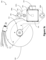
- An actuation shaft 206 also extends between the end plates 204 and through an actuation nut 308 of the material removal machine 300 (see, e.g., FIG. 3c ).
- rotation of the actuation shaft 206 in conjunction with engagement with the actuation nut 308 causes movement of the material removal machine 300.
- an actuation unit 208 may further rotate the lower support rail 202b, and thereby cause rotational movement of the end plates 204 and material removal machine 300.
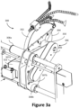
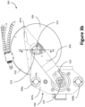
- FIGS. 3a-3d show various views of the material removal machine 300.
- FIG. 3a is an enlarged rear perspective view
- FIGS. 3b and 3c are side views of the material removal machine 300, with some of the other elements of the material removal assembly 200 removed for the sake of clarity.
- the material removal machine 300 includes a material removal tool 304 (e.g., a saw blade, abrasive saw, grinder, polisher, etc.) retained on a spindle 310 that is at least partially encased in a spindle housing 330 of the support 306.
- the material removal tool 304 is a disc.
- the support 306 comprises two substantially parallel support plates 307: a first support plate 307a and a second support plate 307b.
- the support plate 307a includes the nut 302.
- a shield 332 connected to the support plate 307a partially encloses (and/or encases) the material removal tool 300.
- the support plates 307 are connected through the sleeves 308 (upper sleeve 308a and lower sleeve 308b), the spindle housing 330, and a tool actuator housing 322.
- the tool actuator housing 322 encloses a tool actuator 320 and/or tool actuator controller 324.
- the tool actuator 320 and/or tool actuator controller 324 may be powered by the power source 108, or may be powered by a separate power source retained within the tool actuator housing 322.
- the tool actuator 320 is in mechanical communication with an actuator pulley 316.
- the tool actuator 320 e.g., an electrical motor
- the actuator pulley 316 is mechanically connected to a spindle pulley 314 via a belt 318.
- the actuator pulley 316, spindle pulley 314, and belt 318 are substantially encased within an arm 340 of the support 307.
- the belt 318 translates actuation (e.g., movement, rotation, turning, spinning, etc.) of the actuator pulley 316 into actuation (e.g., movement, rotation, turning, spinning, etc.) of the spindle pulley 314.
- the spindle pulley 314 is secured to the spindle 310, such that actuation (e.g., movement, rotation, turning, spinning, etc.) of the actuator pulley 316 by the tool actuator 320 translates into actuation (e.g., movement, rotation, turning, spinning, etc.) of the spindle 310 and/or material removal tool 304 via the spindle pulley 314.
- the spindle 310 extends through an approximate center (and/or central aperture) of the material removal tool 304 and the spindle pulley 314.
- a fastener 312 attaches to an end of the spindle 310 and secures the material removal tool 304 on the spindle 310 between flanges 342.
- the fastener 312 is a nut, but in other examples the fastener 312 may be a nut, bolt, screw, nail, and/or any other type of appropriate fastener.
- the spindle 310 is retained by the hub 350.
- the hub 350 is substantially cylindrical, and includes a collar 352 at an end of the hub 350, with a body 354 extending from the collar 352.
- the collar 352 has a larger outer diameter than the body 354.
- the collar 352 also includes pin holes 356 around the circumference of the collar 352.
- the pin holes 356 are configured to engage pins of a pin wrench, allowing the pin wrench to grip and/or move (e.g., turn, rotate, spin, etc.) the collar 352 when the collar is unlocked.
- plate seals 344 and ball bearings 346 are pinched between the hub 350 and the spindle 310 to help keep the spindle 310 in place, while still allowing the spindle 310 to move (e.g., spin, rotate, turn, etc.) within the hub 350.
- the plate seals 344 additionally serve as seals, to keep lubricant within the hub 350, and debris out of the hub 350.
- an additional seal 348 attaches to the collar 352 of the hub 350 and/or plate seal 344a.
- the body 354 of the hub 350 is retained within the spindle housing 330, such that an outer diameter of the body 354 is less than the inner dimeter of the spindle housing 330.
- the collar 352 is not retained within the spindle housing 330, but is rather substantially aligned (and/or collinear) with the spindle housing 330, such that the collar 352 has an outer diameter approximately equal to the spindle housing 330.
- the hub 350 includes a cylindrical bore 358 that extends through the hub 350 off center (e.g., shifted from a central axis of the hub 350), such that the hub 350 has an eccentric arrangement.
- the spindle 310 is secured within an approximate center of the bore 358. This organization results in the spindle 310 and spindle pulley 314 being retained by the hub 350 at a shifted, off-center, and/or eccentric position with respect to the hub 350, such as shown in the examples of FIGS. 5a-5c .
- the spindle 310 and/or spindle pulley 314 are moved to different positions, rather than simply being spun (and/or rotated, turned, etc.) in place.
- the spindle pulley 314 is advantageously positioned within the arm 340 with enough space so that this movement is possible.
- the actuator pulley 316 is substantially fixed with respect to other components of the material removal machine 300 (e.g., the spindle pulley 314, hub 350, etc.)
- movement of the spindle pulley 314 results in a change in distance between the spindle pulley 314 and the actuator pulley 316. This change in distance in turn results in a change in tension of the belt 318 connecting the spindle pulley 314 and the actuator pulley 316.
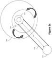
- FIGS. 5a-5c shows an exaggerated example of movement of the hub 350 when the hub 350 is unlocked and, through the hub 350, movement of the spindle pulley 314, spindle 310, and/or material removal machine 300.
- the difference in dimensions of the hub 350 and spindle pulley 314 are exaggerated in FIGS. 5a-5c , to make the operation clearer.
- the spindle pulley 314 is at a first position a first distance D1 from the actuator pulley 316. This results in a first tension in the belt 318.
- the spindle pulley 314 has been moved to a second position a second distance D2 from the actuator pulley 316.
- FIG. 5c shows the spindle pulley 314 at a third position a third distance D1 from the actuator pulley 316. This results in a third tension in the belt 318. As the first distance D1 is less than the third distance D3, the first tension will be less than the third tension. The second distance D2 is also less than the third distance D3, so the second tension will be less than the third tension. Thus, the first or second positions of FIGS. 5a and 5b may be better for attaching and/or removing the belt, while the third position of FIG. 5c may be better for operation of the material removal machine 300 (and/or material removal tool 304).
- a hub plate 360 attaches to the spindle housing 330 proximate to the material removal tool 304, such that the flange 342b abuts the hub plate 360.
- the hub plate 360 is configured to compress the spindle housing 330 when the hub plate 360 is tightened onto the spindle housing 330, so as to lock the hub 350 in place. More particularly, when the hub plate 360 compresses the spindle housing 330, the spindle housing 330 squeezes tightly against the hub 350, preventing movement (e.g., rotation, turning, spinning, etc.) of the hub 350.
- the spindle housing 330 When the hub plate 360 is loosened, the spindle housing 330 is allowed to expand somewhat, giving the hub plate 360 room to move (e.g., spin, turn, rotate, etc.) within the spindle housing 330.
- hub plate fasteners (not shown) may be used to loosen and/or tighten the hub plate 360.
- the hub plate 360 provides a mechanism through which the hub 350 may be locked and/or unlocked.
- an operator may initially attach the belt 318 to the material removal machine 300.
- the operator may wish to move the hub 350 so that the spindle pulley 314 is closer to the actuator pulley 316.
- the operator may unlock the hub 350 by loosening the hub plate 360.
- the fastener 312, material removal tool 304, and/or flanges 342 may need to be removed from the spindle 310. While the removal of these components to access the hub plate 360 may be slightly inconvenient, the obstructed access may help prevent accidental loosening of the hub plate 360.
- the operator may adjust the hub 350, such as via a pin wrench for example. For example, the operator may adjust the hub 350 to position similar to the first position illustrated in FIG. 5a . The operator may then attach the belt 318 to the spindle pulley 314 and/or actuator pulley 316, stretching the belt 318 as necessary. Once the belt 318 is attached, the operator may move the hub 350 to a position where the belt 318 will have a higher tension, which may be better for operation of the material removal machine 300 (and/or material removal tool 304). For example, the operator may adjust the hub 350 to position similar to the second or third position illustrated in FIGS. 5b and 5c .
- the operator may tighten the hub plate 360 so as to lock the hub 350 in place, then reattach the flanges 342, material removal tool 304, and/or fastener 312.
- the material removal machine 300 may be ready for operation through actuation of the material removal tool 304 via the tool actuator 320, actuator pulley 316, belt 318, spindle pulley 314, and/or spindle 310.
Landscapes
- Engineering & Computer Science (AREA)
- Mechanical Engineering (AREA)
- General Engineering & Computer Science (AREA)
- Devices For Conveying Motion By Means Of Endless Flexible Members (AREA)
- Finish Polishing, Edge Sharpening, And Grinding By Specific Grinding Devices (AREA)
- Constituent Portions Of Griding Lathes, Driving, Sensing And Control (AREA)
- Sawing (AREA)
Claims (15)
- Materialentfernungsvorrichtung, aufweisend:eine Spindel (310), die dafür ausgelegt ist, ein Materialentfernungswerkzeug (304) zu halten;eine Spindelscheibe (314), die an der Spindel befestigt ist, wobei die Spindelscheibe (314) dafür ausgelegt ist, die Spindel anzutreiben; undeine Nabe (350) mit einem Körper (354), der die Spindel (310) so hält, dass ein Außendurchmesser des Körpers (354) kleiner als der Innendurchmesser eines Spindelgehäuses (330) ist, wobei die Nabe (350) dafür ausgelegt ist, eine Position der Spindelscheibe (314) zu verändern,wobei die Vorrichtung ferner eine Nabenverriegelung aufweist, die so ausgelegt ist, dass sie eine Bewegung der Nabe (350) verhindert, wenn sie eingerastet ist, und eine Bewegung der Nabe zulässt, wenn sie gelöst ist,wobei die Nabenverriegelung an dem Spindelgehäuse (330), das zumindest einen Teil der Nabe (350) und der Spindel (310) umgibt, befestigt ist,wobei die Materialentfernungsvorrichtung ferner eine Nabenplatte (360) aufweist, die an dem Spindelgehäuse (330) in der Nähe des Materialentfernungswerkzeugs (304) angebracht ist; undwobei die Nabenverriegelung so ausgelegt ist, dass sie das Spindelgehäuse (330) zusammendrückt, wenn die Nabenplatte (360) an dem Spindelgehäuse (330) festgezogen wird, um die Nabe (350) zu arretieren.
- Vorrichtung nach Anspruch 1, die ferner eine Antriebsscheibe (316) aufweist, die dafür ausgelegt ist, die Spindelscheibe (314) mittels eines Riemens (318) anzutreiben, wobei die Nabe (350) dafür ausgelegt ist, die Position der Spindelscheibe (314) in Bezug auf die Antriebsscheibe (316) zu verändern.
- Vorrichtung nach Anspruch 2, wobei die Nabe (350) dafür ausgelegt ist, die Spindelscheibe (314) aus einer ersten Position in einem ersten Abstand von der Antriebsscheibe (316) in eine zweite Position in einem zweiten Abstand von der Antriebsscheibe (316) zu bewegen, wobei sich der erste Abstand von dem zweiten Abstand unterscheidet.
- Vorrichtung nach Anspruch 3, wobei der Riemen (318) eine erste Spannung aufweist, wenn sich die Spindelscheibe (314) in der ersten Position befindet, und eine zweite Spannung, wenn sich die Spindelscheibe (314) in der zweiten Position befindet, wobei sich die erste Spannung von der zweiten Spannung unterscheidet.
- Vorrichtung nach Anspruch 3, die ferner einen Aktuator (320) aufweist, der dafür ausgelegt ist, die Antriebsscheibe (316) anzutreiben.
- Vorrichtung nach Anspruch 1, wobei die Nabe (350) so ausgelegt ist, dass sie die Position der Spindelscheibe (314) verändert, indem sie die Position der Spindel (310) verändert.
- Verfahren zum Anpassen der Riemenspannung in einer Materialentfernungsmaschine (300), umfassend:Anpassen einer Position einer Spindelscheibe (314) der Materialentfernungsmaschine (300) mittels einer Nabe (350) der Materialentfernungsmaschine (300), wobei die Spindelscheibe (314) dafür ausgelegt ist, ein Materialentfernungswerkzeug (304) der Materialentfernungsmaschine (300) anzutreiben, wobei die Materialentfernungsmaschine (300) ferner Folgendes aufweisteine Nabe (350) mit einem Körper (354), der eine Spindel (310) so hält, dass ein Außendurchmesser des Körpers (354) kleiner als der Innendurchmesser eines Spindelgehäuses (330) ist, wobei die Nabe (350) dafür ausgelegt ist, eine Position der Spindelscheibe (314) zu verändern; undeine Nabenverriegelung, die so ausgelegt ist, dass sie eine Bewegung der Nabe (350) verhindert, wenn sie eingerastet ist, und eine Bewegung der Nabe zulässt, wenn sie gelöst ist,wobei die Nabenverriegelung an dem Spindelgehäuse (330), das zumindest einen Teil der Nabe (350) und der Spindel (310) umgibt, befestigt ist,wobei die Materialentfernungsvorrichtung ferner eine Nabenplatte (360) aufweist, die an dem Spindelgehäuse (330) in der Nähe des Materialentfernungswerkzeugs (304) angebracht ist; undwobei die Nabenverriegelung so ausgelegt ist, dass sie das Spindelgehäuse (330) zusammendrückt, wenn die Nabenplatte (360) an dem Spindelgehäuse (330) festgezogen wird, um die Nabe (350) zu arretieren.
- Verfahren nach Anspruch 7, wobei das Anpassen der Position der Spindelscheibe (314) ein Anpassen der Position der Spindelscheibe (314) in Bezug auf eine Antriebsscheibe (316) der Materialentfernungsmaschine umfasst.
- Verfahren nach Anspruch 7, wobei das Anpassen der Position der Spindelscheibe (314) ein Bewegen der Spindelscheibe (310) aus einer ersten Position in einem ersten Abstand von einer Antriebsscheibe (316) in eine zweite Position in einem zweiten Abstand von der Antriebsscheibe (316) umfasst, wobei sich der erste Abstand von dem zweiten Abstand unterscheidet, und wobei ein Riemen (318), der die Spindelscheibe (314) mit der Antriebsscheibe (316) verbindet, optional eine erste Spannung aufweist, wenn sich die Spindelscheibe (314) in der ersten Position befindet, und eine zweite Spannung, wenn sich die Spindelscheibe (314) in der zweiten Position befindet, wobei sich die erste Spannung von der zweiten Spannung unterscheidet.
- Verfahren nach Anspruch 9, das ferner ein Antreiben des Materialentfernungswerkzeugs (304) über die Spindelscheibe (314) umfasst.
- Verfahren nach Anspruch 10, wobei das Antreiben des Materialentfernungswerkzeugs (304) über die Spindelscheibe (314) ein Übersetzen des Antriebs der Antriebsscheibe (316) in einen Antrieb der Spindelscheibe (314) durch den Riemen (318), der die Antriebsscheibe (316) und die Spindelscheibe (314) verbindet, umfasst.
- Verfahren nach Anspruch 7, das ferner ein Erhalten von Zugang zu der Nabenverriegelung der Materialentfernungsmaschine (300) und ein Freigeben der Nabe (350) über die Nabenverriegelung vor dem Anpassen der Position der Spindelscheibe umfasst.
- Verfahren nach Anspruch 7, das ferner ein Erhalten von Zugang zu der Nabenverriegelung der Materialentfernungsmaschine und ein Verriegeln der Nabe über die Nabenverriegelung nach dem Anpassen der Position der Spindelscheibe umfasst.
- Verfahren nach Anspruch 7, wobei die Spindelscheibe (314) an der Spindel (310) der Materialentfernungsmaschine (300) befestigt ist, das Materialentfernungswerkzeug (304) an der Spindel (310) gehalten wird und die Spindel (310) durch die Nabe (350) gehalten wird.
- Verfahren nach Anspruch 7, wobei das Anpassen der Position einer Spindelscheibe (314) mittels der Nabe (350) ein Einstellen der Nabe (350) unter Verwendung eines Werkzeugs, das in Eingriffsmerkmale der Nabe (350) eingreift, umfasst.
Applications Claiming Priority (3)
| Application Number | Priority Date | Filing Date | Title |
|---|---|---|---|
| US201862724145P | 2018-08-29 | 2018-08-29 | |
| US16/517,183 US11549571B2 (en) | 2018-08-29 | 2019-07-19 | Belt tensioning apparatus for material removal machines |
| PCT/US2019/048711 WO2020047190A1 (en) | 2018-08-29 | 2019-08-29 | Belt tensioning apparatus for material removal machines |
Publications (2)
| Publication Number | Publication Date |
|---|---|
| EP3843944A1 EP3843944A1 (de) | 2021-07-07 |
| EP3843944B1 true EP3843944B1 (de) | 2024-10-30 |
Family
ID=69639720
Family Applications (1)
| Application Number | Title | Priority Date | Filing Date |
|---|---|---|---|
| EP19769291.6A Active EP3843944B1 (de) | 2018-08-29 | 2019-08-29 | Riemenspannvorrichtung für materialabtragungsmaschinen |
Country Status (5)
| Country | Link |
|---|---|
| US (1) | US11549571B2 (de) |
| EP (1) | EP3843944B1 (de) |
| JP (1) | JP7524162B2 (de) |
| CN (1) | CN113039043B (de) |
| WO (1) | WO2020047190A1 (de) |
Families Citing this family (2)
| Publication number | Priority date | Publication date | Assignee | Title |
|---|---|---|---|---|
| US12179299B2 (en) * | 2018-08-07 | 2024-12-31 | Illinois Tool Works Inc. | Machine tool with recirculating coolant filtration system |
| US12403539B2 (en) * | 2020-09-16 | 2025-09-02 | Illinois Tool Works Inc. | Standpipe recirculation systems for material removal machines |
Family Cites Families (34)
| Publication number | Priority date | Publication date | Assignee | Title |
|---|---|---|---|---|
| GB728125A (en) * | 1951-02-07 | 1955-04-13 | Terrot Ets | Progressive change speed gear utilising extensible pulleys |
| US3735489A (en) * | 1971-02-18 | 1973-05-29 | Textron Inc | Hand-held power tool with rotary tool disc at end of reversible forwardly projecting arm |
| US4568318A (en) * | 1982-12-15 | 1986-02-04 | Lear Siegler, Inc. | Belt tensioning apparatus for belt/pulley drive system |
| US4620367A (en) * | 1985-03-11 | 1986-11-04 | Tubesing William W | Saw drive tensioner |
| DE3841644C2 (de) * | 1988-12-10 | 1997-12-11 | Stihl Maschf Andreas | Handwerkzeugmaschine, insbesondere Schleif- oder Trennschleifmaschine, mit einer Spannvorrichtung für den Riementrieb |
| US5730561A (en) * | 1996-05-16 | 1998-03-24 | Wambeke; James R. | Universal chop saw |
| PL186552B1 (pl) | 1996-08-21 | 2004-01-30 | Ontario Inc 730143 | Napinacz pasa pojazdu mechanicznego |
| DE19753304A1 (de) * | 1997-12-02 | 1999-06-10 | Scintilla Ag | Vorrichtung zur Arretierung einer Welle |
| JP2001323974A (ja) | 2000-05-17 | 2001-11-22 | Yokohama Rubber Co Ltd:The | 切断装置の伝達機構 |
| ES2249603T3 (es) * | 2001-07-31 | 2006-04-01 | Litens Automotive Partnership | Tensores de correa con pasador de instalacion. |
| US6855079B2 (en) * | 2002-09-30 | 2005-02-15 | Fenner, Inc. | Bi-directional belt tensioner |
| US8413645B2 (en) * | 2005-03-23 | 2013-04-09 | Husqvarna Ab | Cutting or sawing machine |
| DE102005043118A1 (de) * | 2005-09-10 | 2007-03-15 | Andreas Stihl Ag & Co. Kg | Arbeitsgerät |
| EP1943438A1 (de) | 2005-11-03 | 2008-07-16 | Multiquip, Inc. | Ausrückbare riementriebanordnungen für pflastersägen |
| ITVI20070150A1 (it) | 2007-05-25 | 2008-11-26 | Simec Spa | Dispositivo di tensionamento di elementi anulari flessibili ed assieme tensionatore comprendente tale dispositivo. |
| GB2450720A (en) * | 2007-07-04 | 2009-01-07 | Black & Decker Inc | Power cutter with pleated filter |
| US8272134B2 (en) * | 2007-07-04 | 2012-09-25 | Black & Decker Inc. | Power cutter |
| DE102007032672B4 (de) * | 2007-07-13 | 2020-07-09 | Andreas Stihl Ag & Co. Kg | Schutzhaube eines handgeführten Trennschleifers |
| DE102008023927A1 (de) * | 2008-05-16 | 2009-11-19 | Andreas Stihl Ag & Co. Kg | Arbeitsgerät |
| WO2010126678A2 (en) * | 2009-05-01 | 2010-11-04 | Illinois Tool Works Inc. | Improved abrasive saw |
| JP2013512784A (ja) * | 2009-12-03 | 2013-04-18 | センブレ エス.ピー.エー. | ワークピースのツーリング用装置 |
| RU2513610C2 (ru) * | 2009-12-16 | 2014-04-20 | Хускварна Аб | Узел инструмента и инструмент для отрезного или пильного станка |
| EP2478984B1 (de) * | 2011-01-20 | 2015-03-25 | Makita Corporation | Motorarbeitsgerät mit einer Spanneinrichtung für einen Riemen |
| DE202011000143U1 (de) | 2011-01-20 | 2012-06-08 | Makita Corporation | Motorarbeitsgerät mit einer Spanneinrichtung für einen Riemen |
| DE202012103489U1 (de) | 2012-09-13 | 2013-12-19 | Makita Corp. | Riementrieb für ein Motorarbeitsgerät |
| DE202013100690U1 (de) * | 2013-02-15 | 2014-05-16 | Makita Corp. | Schneidwerkzeugmaschine |
| DE102013012746A1 (de) * | 2013-07-31 | 2015-02-05 | Andreas Stihl Ag & Co. Kg | Handgeführtes Arbeitsgerät |
| US20170138445A1 (en) * | 2014-06-27 | 2017-05-18 | Litens Automotive Partnership | Endless drive arrangement with active idler |
| EP3173187A1 (de) * | 2015-11-25 | 2017-05-31 | HILTI Aktiengesellschaft | Tragbare, handgeführte trennschleifmaschine |
| SE542092C2 (en) * | 2016-06-03 | 2020-02-25 | Husqvarna Ab | Grinding head for floor grinding machine and a floor grinding machine comprising such a grinding head |
| CN206010742U (zh) * | 2016-08-19 | 2017-03-15 | 温州隆佳自动化设备有限公司 | 抛光机及其抛光头 |
| SE541380C2 (en) * | 2017-05-03 | 2019-09-10 | Husqvarna Ab | Power tool comprising a draining channel |
| EP3645200B1 (de) * | 2017-06-26 | 2023-12-27 | Milwaukee Electric Tool Corporation | Trennsäge |
| DE102017008391A1 (de) * | 2017-09-07 | 2019-03-07 | Andreas Stihl Ag & Co. Kg | Arbeitsgerät und Verfahren zu dessen Betrieb |
-
2019
- 2019-07-19 US US16/517,183 patent/US11549571B2/en active Active
- 2019-08-29 EP EP19769291.6A patent/EP3843944B1/de active Active
- 2019-08-29 WO PCT/US2019/048711 patent/WO2020047190A1/en not_active Ceased
- 2019-08-29 CN CN201980054938.2A patent/CN113039043B/zh active Active
- 2019-08-29 JP JP2021511563A patent/JP7524162B2/ja active Active
Also Published As
| Publication number | Publication date |
|---|---|
| EP3843944A1 (de) | 2021-07-07 |
| US20200072324A1 (en) | 2020-03-05 |
| CN113039043B (zh) | 2023-07-07 |
| JP7524162B2 (ja) | 2024-07-29 |
| JP2021534991A (ja) | 2021-12-16 |
| US11549571B2 (en) | 2023-01-10 |
| WO2020047190A1 (en) | 2020-03-05 |
| CN113039043A (zh) | 2021-06-25 |
Similar Documents
| Publication | Publication Date | Title |
|---|---|---|
| US4597227A (en) | Device for attaching a tool | |
| JP2980269B2 (ja) | 工作機械 | |
| JP5019535B2 (ja) | 工具用クランプ機器を有するハンドヘルド電動工具 | |
| US4630512A (en) | Adjustable motor-operated screw driving device | |
| JP3288379B2 (ja) | 偏心ディスクグラインダ | |
| EP3843944B1 (de) | Riemenspannvorrichtung für materialabtragungsmaschinen | |
| CN101579756B (zh) | 工作器具 | |
| JP3655848B2 (ja) | 携帯型ロータリー突切りディスク | |
| DE50106395D1 (de) | Werkzeugaufnahme | |
| US20220388109A1 (en) | Quick Clamping Device | |
| JPH02501907A (ja) | 工具、特にディスク類を軸方向で締め付け固定するための緊締装置 | |
| DE10343060A1 (de) | Handwerkzeugmaschine mit Schutzhaube | |
| EP0820838B1 (de) | Schleifer mit einem mit Exzenterhub angetriebenen Werkzeug | |
| US10682736B2 (en) | Accessory clamp and spindle lock mechanism for power tool | |
| JPH02501547A (ja) | 携帯用の手持工作機械、特にアングル研削盤 | |
| DE4344128A1 (de) | Elektrische Handwerkzeugmaschine | |
| CN1157587A (zh) | 电动手工工具机 | |
| JP7449923B2 (ja) | 材料除去機の保持装置 | |
| DE69405935T2 (de) | Vorrichtung zum manuellen Anbringen und Abmontieren von Bearbeitungsscheiben auf Handwerkzeugmaschinen für Oberflächenbearbeitung | |
| GB2562436A (en) | Belt-type grinding tool | |
| WO2009066798A1 (en) | Power tool comprising a wheel guard | |
| US6296586B1 (en) | Tensioning device for a chain or a belt drive for a motor of a hand machine tool | |
| KR20120025145A (ko) | 전동공구 액세서리 | |
| US5709594A (en) | Portable motor or engine-driven cutting-off machine | |
| DE4344571A1 (de) | Elektrische Handwerkzeugmaschine |
Legal Events
| Date | Code | Title | Description |
|---|---|---|---|
| STAA | Information on the status of an ep patent application or granted ep patent |
Free format text: STATUS: UNKNOWN |
|
| STAA | Information on the status of an ep patent application or granted ep patent |
Free format text: STATUS: THE INTERNATIONAL PUBLICATION HAS BEEN MADE |
|
| STAA | Information on the status of an ep patent application or granted ep patent |
Free format text: STATUS: REQUEST FOR EXAMINATION WAS MADE |
|
| PUAI | Public reference made under article 153(3) epc to a published international application that has entered the european phase |
Free format text: ORIGINAL CODE: 0009012 |
|
| 17P | Request for examination filed |
Effective date: 20210211 |
|
| AK | Designated contracting states |
Kind code of ref document: A1 Designated state(s): AL AT BE BG CH CY CZ DE DK EE ES FI FR GB GR HR HU IE IS IT LI LT LU LV MC MK MT NL NO PL PT RO RS SE SI SK SM TR |
|
| DAV | Request for validation of the european patent (deleted) | ||
| DAX | Request for extension of the european patent (deleted) | ||
| GRAP | Despatch of communication of intention to grant a patent |
Free format text: ORIGINAL CODE: EPIDOSNIGR1 |
|
| STAA | Information on the status of an ep patent application or granted ep patent |
Free format text: STATUS: GRANT OF PATENT IS INTENDED |
|
| INTG | Intention to grant announced |
Effective date: 20240215 |
|
| GRAJ | Information related to disapproval of communication of intention to grant by the applicant or resumption of examination proceedings by the epo deleted |
Free format text: ORIGINAL CODE: EPIDOSDIGR1 |
|
| STAA | Information on the status of an ep patent application or granted ep patent |
Free format text: STATUS: REQUEST FOR EXAMINATION WAS MADE |
|
| GRAP | Despatch of communication of intention to grant a patent |
Free format text: ORIGINAL CODE: EPIDOSNIGR1 |
|
| STAA | Information on the status of an ep patent application or granted ep patent |
Free format text: STATUS: GRANT OF PATENT IS INTENDED |
|
| INTC | Intention to grant announced (deleted) | ||
| INTG | Intention to grant announced |
Effective date: 20240625 |
|
| GRAS | Grant fee paid |
Free format text: ORIGINAL CODE: EPIDOSNIGR3 |
|
| P01 | Opt-out of the competence of the unified patent court (upc) registered |
Free format text: CASE NUMBER: APP_47940/2024 Effective date: 20240820 |
|
| GRAA | (expected) grant |
Free format text: ORIGINAL CODE: 0009210 |
|
| STAA | Information on the status of an ep patent application or granted ep patent |
Free format text: STATUS: THE PATENT HAS BEEN GRANTED |
|
| AK | Designated contracting states |
Kind code of ref document: B1 Designated state(s): AL AT BE BG CH CY CZ DE DK EE ES FI FR GB GR HR HU IE IS IT LI LT LU LV MC MK MT NL NO PL PT RO RS SE SI SK SM TR |
|
| REG | Reference to a national code |
Ref country code: GB Ref legal event code: FG4D |
|
| REG | Reference to a national code |
Ref country code: CH Ref legal event code: EP |
|
| REG | Reference to a national code |
Ref country code: IE Ref legal event code: FG4D |
|
| REG | Reference to a national code |
Ref country code: DE Ref legal event code: R096 Ref document number: 602019061162 Country of ref document: DE |
|
| REG | Reference to a national code |
Ref country code: LT Ref legal event code: MG9D |
|
| REG | Reference to a national code |
Ref country code: NL Ref legal event code: MP Effective date: 20241030 |
|
| PG25 | Lapsed in a contracting state [announced via postgrant information from national office to epo] |
Ref country code: IS Free format text: LAPSE BECAUSE OF FAILURE TO SUBMIT A TRANSLATION OF THE DESCRIPTION OR TO PAY THE FEE WITHIN THE PRESCRIBED TIME-LIMIT Effective date: 20250228 Ref country code: HR Free format text: LAPSE BECAUSE OF FAILURE TO SUBMIT A TRANSLATION OF THE DESCRIPTION OR TO PAY THE FEE WITHIN THE PRESCRIBED TIME-LIMIT Effective date: 20241030 Ref country code: PT Free format text: LAPSE BECAUSE OF FAILURE TO SUBMIT A TRANSLATION OF THE DESCRIPTION OR TO PAY THE FEE WITHIN THE PRESCRIBED TIME-LIMIT Effective date: 20250228 |
|
| PG25 | Lapsed in a contracting state [announced via postgrant information from national office to epo] |
Ref country code: FI Free format text: LAPSE BECAUSE OF FAILURE TO SUBMIT A TRANSLATION OF THE DESCRIPTION OR TO PAY THE FEE WITHIN THE PRESCRIBED TIME-LIMIT Effective date: 20241030 Ref country code: NL Free format text: LAPSE BECAUSE OF FAILURE TO SUBMIT A TRANSLATION OF THE DESCRIPTION OR TO PAY THE FEE WITHIN THE PRESCRIBED TIME-LIMIT Effective date: 20241030 |
|
| REG | Reference to a national code |
Ref country code: AT Ref legal event code: MK05 Ref document number: 1736455 Country of ref document: AT Kind code of ref document: T Effective date: 20241030 |
|
| PG25 | Lapsed in a contracting state [announced via postgrant information from national office to epo] |
Ref country code: BG Free format text: LAPSE BECAUSE OF FAILURE TO SUBMIT A TRANSLATION OF THE DESCRIPTION OR TO PAY THE FEE WITHIN THE PRESCRIBED TIME-LIMIT Effective date: 20241030 |
|
| PG25 | Lapsed in a contracting state [announced via postgrant information from national office to epo] |
Ref country code: ES Free format text: LAPSE BECAUSE OF FAILURE TO SUBMIT A TRANSLATION OF THE DESCRIPTION OR TO PAY THE FEE WITHIN THE PRESCRIBED TIME-LIMIT Effective date: 20241030 |
|
| PG25 | Lapsed in a contracting state [announced via postgrant information from national office to epo] |
Ref country code: NO Free format text: LAPSE BECAUSE OF FAILURE TO SUBMIT A TRANSLATION OF THE DESCRIPTION OR TO PAY THE FEE WITHIN THE PRESCRIBED TIME-LIMIT Effective date: 20250130 |
|
| PG25 | Lapsed in a contracting state [announced via postgrant information from national office to epo] |
Ref country code: GR Free format text: LAPSE BECAUSE OF FAILURE TO SUBMIT A TRANSLATION OF THE DESCRIPTION OR TO PAY THE FEE WITHIN THE PRESCRIBED TIME-LIMIT Effective date: 20250131 Ref country code: LV Free format text: LAPSE BECAUSE OF FAILURE TO SUBMIT A TRANSLATION OF THE DESCRIPTION OR TO PAY THE FEE WITHIN THE PRESCRIBED TIME-LIMIT Effective date: 20241030 Ref country code: AT Free format text: LAPSE BECAUSE OF FAILURE TO SUBMIT A TRANSLATION OF THE DESCRIPTION OR TO PAY THE FEE WITHIN THE PRESCRIBED TIME-LIMIT Effective date: 20241030 |
|
| PG25 | Lapsed in a contracting state [announced via postgrant information from national office to epo] |
Ref country code: PL Free format text: LAPSE BECAUSE OF FAILURE TO SUBMIT A TRANSLATION OF THE DESCRIPTION OR TO PAY THE FEE WITHIN THE PRESCRIBED TIME-LIMIT Effective date: 20241030 |
|
| PG25 | Lapsed in a contracting state [announced via postgrant information from national office to epo] |
Ref country code: RS Free format text: LAPSE BECAUSE OF FAILURE TO SUBMIT A TRANSLATION OF THE DESCRIPTION OR TO PAY THE FEE WITHIN THE PRESCRIBED TIME-LIMIT Effective date: 20250130 |
|
| PG25 | Lapsed in a contracting state [announced via postgrant information from national office to epo] |
Ref country code: SM Free format text: LAPSE BECAUSE OF FAILURE TO SUBMIT A TRANSLATION OF THE DESCRIPTION OR TO PAY THE FEE WITHIN THE PRESCRIBED TIME-LIMIT Effective date: 20241030 |
|
| PG25 | Lapsed in a contracting state [announced via postgrant information from national office to epo] |
Ref country code: DK Free format text: LAPSE BECAUSE OF FAILURE TO SUBMIT A TRANSLATION OF THE DESCRIPTION OR TO PAY THE FEE WITHIN THE PRESCRIBED TIME-LIMIT Effective date: 20241030 |
|
| PG25 | Lapsed in a contracting state [announced via postgrant information from national office to epo] |
Ref country code: EE Free format text: LAPSE BECAUSE OF FAILURE TO SUBMIT A TRANSLATION OF THE DESCRIPTION OR TO PAY THE FEE WITHIN THE PRESCRIBED TIME-LIMIT Effective date: 20241030 |
|
| PG25 | Lapsed in a contracting state [announced via postgrant information from national office to epo] |
Ref country code: RO Free format text: LAPSE BECAUSE OF FAILURE TO SUBMIT A TRANSLATION OF THE DESCRIPTION OR TO PAY THE FEE WITHIN THE PRESCRIBED TIME-LIMIT Effective date: 20241030 |
|
| PG25 | Lapsed in a contracting state [announced via postgrant information from national office to epo] |
Ref country code: SK Free format text: LAPSE BECAUSE OF FAILURE TO SUBMIT A TRANSLATION OF THE DESCRIPTION OR TO PAY THE FEE WITHIN THE PRESCRIBED TIME-LIMIT Effective date: 20241030 |
|
| PG25 | Lapsed in a contracting state [announced via postgrant information from national office to epo] |
Ref country code: CZ Free format text: LAPSE BECAUSE OF FAILURE TO SUBMIT A TRANSLATION OF THE DESCRIPTION OR TO PAY THE FEE WITHIN THE PRESCRIBED TIME-LIMIT Effective date: 20241030 |
|
| PG25 | Lapsed in a contracting state [announced via postgrant information from national office to epo] |
Ref country code: IT Free format text: LAPSE BECAUSE OF FAILURE TO SUBMIT A TRANSLATION OF THE DESCRIPTION OR TO PAY THE FEE WITHIN THE PRESCRIBED TIME-LIMIT Effective date: 20241030 |
|
| REG | Reference to a national code |
Ref country code: DE Ref legal event code: R097 Ref document number: 602019061162 Country of ref document: DE |
|
| PLBE | No opposition filed within time limit |
Free format text: ORIGINAL CODE: 0009261 |
|
| STAA | Information on the status of an ep patent application or granted ep patent |
Free format text: STATUS: NO OPPOSITION FILED WITHIN TIME LIMIT |
|
| PG25 | Lapsed in a contracting state [announced via postgrant information from national office to epo] |
Ref country code: SE Free format text: LAPSE BECAUSE OF FAILURE TO SUBMIT A TRANSLATION OF THE DESCRIPTION OR TO PAY THE FEE WITHIN THE PRESCRIBED TIME-LIMIT Effective date: 20241030 |
|
| 26N | No opposition filed |
Effective date: 20250731 |
|
| PGFP | Annual fee paid to national office [announced via postgrant information from national office to epo] |
Ref country code: DE Payment date: 20250827 Year of fee payment: 7 |
|
| PGFP | Annual fee paid to national office [announced via postgrant information from national office to epo] |
Ref country code: GB Payment date: 20250827 Year of fee payment: 7 |
|
| REG | Reference to a national code |
Ref country code: CH Ref legal event code: H13 Free format text: ST27 STATUS EVENT CODE: U-0-0-H10-H13 (AS PROVIDED BY THE NATIONAL OFFICE) Effective date: 20260324 |
|
| PG25 | Lapsed in a contracting state [announced via postgrant information from national office to epo] |
Ref country code: MC Free format text: LAPSE BECAUSE OF FAILURE TO SUBMIT A TRANSLATION OF THE DESCRIPTION OR TO PAY THE FEE WITHIN THE PRESCRIBED TIME-LIMIT Effective date: 20241030 |
|
| PG25 | Lapsed in a contracting state [announced via postgrant information from national office to epo] |
Ref country code: LU Free format text: LAPSE BECAUSE OF NON-PAYMENT OF DUE FEES Effective date: 20250829 |
|
| PG25 | Lapsed in a contracting state [announced via postgrant information from national office to epo] |
Ref country code: CH Free format text: LAPSE BECAUSE OF NON-PAYMENT OF DUE FEES Effective date: 20250831 |