EP3835144B1 - System mit einem motorrad und einer transportablen funkvorrichtung - Google Patents
System mit einem motorrad und einer transportablen funkvorrichtung Download PDFInfo
- Publication number
- EP3835144B1 EP3835144B1 EP20198024.0A EP20198024A EP3835144B1 EP 3835144 B1 EP3835144 B1 EP 3835144B1 EP 20198024 A EP20198024 A EP 20198024A EP 3835144 B1 EP3835144 B1 EP 3835144B1
- Authority
- EP
- European Patent Office
- Prior art keywords
- control device
- motorcycle
- radio device
- motorbike
- information
- Prior art date
- Legal status (The legal status is an assumption and is not a legal conclusion. Google has not performed a legal analysis and makes no representation as to the accuracy of the status listed.)
- Active
Links
Images


Classifications
-
- B—PERFORMING OPERATIONS; TRANSPORTING
- B60—VEHICLES IN GENERAL
- B60R—VEHICLES, VEHICLE FITTINGS, OR VEHICLE PARTS, NOT OTHERWISE PROVIDED FOR
- B60R25/00—Fittings or systems for preventing or indicating unauthorised use or theft of vehicles
- B60R25/20—Means to switch the anti-theft system on or off
- B60R25/24—Means to switch the anti-theft system on or off using electronic identifiers containing a code not memorised by the user
-
- B—PERFORMING OPERATIONS; TRANSPORTING
- B62—LAND VEHICLES FOR TRAVELLING OTHERWISE THAN ON RAILS
- B62J—CYCLE SADDLES OR SEATS; AUXILIARY DEVICES OR ACCESSORIES SPECIALLY ADAPTED TO CYCLES AND NOT OTHERWISE PROVIDED FOR, e.g. ARTICLE CARRIERS OR CYCLE PROTECTORS
- B62J45/00—Electrical equipment arrangements specially adapted for use as accessories on cycles, not otherwise provided for
-
- B—PERFORMING OPERATIONS; TRANSPORTING
- B62—LAND VEHICLES FOR TRAVELLING OTHERWISE THAN ON RAILS
- B62H—CYCLE STANDS; SUPPORTS OR HOLDERS FOR PARKING OR STORING CYCLES; APPLIANCES PREVENTING OR INDICATING UNAUTHORIZED USE OR THEFT OF CYCLES; LOCKS INTEGRAL WITH CYCLES; DEVICES FOR LEARNING TO RIDE CYCLES
- B62H5/00—Appliances preventing or indicating unauthorised use or theft of cycles; Locks integral with cycles
- B62H5/001—Preventing theft of parts or accessories used on cycles, e.g. lamp, dynamo
-
- B—PERFORMING OPERATIONS; TRANSPORTING
- B62—LAND VEHICLES FOR TRAVELLING OTHERWISE THAN ON RAILS
- B62H—CYCLE STANDS; SUPPORTS OR HOLDERS FOR PARKING OR STORING CYCLES; APPLIANCES PREVENTING OR INDICATING UNAUTHORIZED USE OR THEFT OF CYCLES; LOCKS INTEGRAL WITH CYCLES; DEVICES FOR LEARNING TO RIDE CYCLES
- B62H5/00—Appliances preventing or indicating unauthorised use or theft of cycles; Locks integral with cycles
- B62H5/02—Appliances preventing or indicating unauthorised use or theft of cycles; Locks integral with cycles for locking the steering mechanism
- B62H5/04—Appliances preventing or indicating unauthorised use or theft of cycles; Locks integral with cycles for locking the steering mechanism acting on the handlebars or equivalent
-
- B—PERFORMING OPERATIONS; TRANSPORTING
- B62—LAND VEHICLES FOR TRAVELLING OTHERWISE THAN ON RAILS
- B62H—CYCLE STANDS; SUPPORTS OR HOLDERS FOR PARKING OR STORING CYCLES; APPLIANCES PREVENTING OR INDICATING UNAUTHORIZED USE OR THEFT OF CYCLES; LOCKS INTEGRAL WITH CYCLES; DEVICES FOR LEARNING TO RIDE CYCLES
- B62H5/00—Appliances preventing or indicating unauthorised use or theft of cycles; Locks integral with cycles
- B62H5/02—Appliances preventing or indicating unauthorised use or theft of cycles; Locks integral with cycles for locking the steering mechanism
- B62H5/06—Appliances preventing or indicating unauthorised use or theft of cycles; Locks integral with cycles for locking the steering mechanism acting on the front wheel fork or steering head tube
-
- B—PERFORMING OPERATIONS; TRANSPORTING
- B62—LAND VEHICLES FOR TRAVELLING OTHERWISE THAN ON RAILS
- B62H—CYCLE STANDS; SUPPORTS OR HOLDERS FOR PARKING OR STORING CYCLES; APPLIANCES PREVENTING OR INDICATING UNAUTHORIZED USE OR THEFT OF CYCLES; LOCKS INTEGRAL WITH CYCLES; DEVICES FOR LEARNING TO RIDE CYCLES
- B62H5/00—Appliances preventing or indicating unauthorised use or theft of cycles; Locks integral with cycles
- B62H5/08—Appliances preventing or indicating unauthorised use or theft of cycles; Locks integral with cycles preventing the drive
-
- B—PERFORMING OPERATIONS; TRANSPORTING
- B62—LAND VEHICLES FOR TRAVELLING OTHERWISE THAN ON RAILS
- B62J—CYCLE SADDLES OR SEATS; AUXILIARY DEVICES OR ACCESSORIES SPECIALLY ADAPTED TO CYCLES AND NOT OTHERWISE PROVIDED FOR, e.g. ARTICLE CARRIERS OR CYCLE PROTECTORS
- B62J35/00—Fuel tanks specially adapted for motorcycles or engine-assisted cycles; Arrangements thereof
-
- G—PHYSICS
- G07—CHECKING-DEVICES
- G07C—TIME OR ATTENDANCE REGISTERS; REGISTERING OR INDICATING THE WORKING OF MACHINES; GENERATING RANDOM NUMBERS; VOTING OR LOTTERY APPARATUS; ARRANGEMENTS, SYSTEMS OR APPARATUS FOR CHECKING NOT PROVIDED FOR ELSEWHERE
- G07C9/00—Individual registration on entry or exit
- G07C9/00174—Electronically operated locks; Circuits therefor; Nonmechanical keys therefor, e.g. passive or active electrical keys or other data carriers without mechanical keys
- G07C9/00309—Electronically operated locks; Circuits therefor; Nonmechanical keys therefor, e.g. passive or active electrical keys or other data carriers without mechanical keys operated with bidirectional data transmission between data carrier and locks
-
- H—ELECTRICITY
- H04—ELECTRIC COMMUNICATION TECHNIQUE
- H04W—WIRELESS COMMUNICATION NETWORKS
- H04W12/00—Security arrangements; Authentication; Protecting privacy or anonymity
- H04W12/06—Authentication
- H04W12/068—Authentication using credential vaults, e.g. password manager applications or one time password [OTP] applications
-
- H—ELECTRICITY
- H04—ELECTRIC COMMUNICATION TECHNIQUE
- H04W—WIRELESS COMMUNICATION NETWORKS
- H04W12/00—Security arrangements; Authentication; Protecting privacy or anonymity
- H04W12/12—Detection or prevention of fraud
- H04W12/126—Anti-theft arrangements, e.g. protection against subscriber identity module [SIM] cloning
-
- B—PERFORMING OPERATIONS; TRANSPORTING
- B60—VEHICLES IN GENERAL
- B60R—VEHICLES, VEHICLE FITTINGS, OR VEHICLE PARTS, NOT OTHERWISE PROVIDED FOR
- B60R2325/00—Indexing scheme relating to vehicle anti-theft devices
- B60R2325/30—Vehicles applying the vehicle anti-theft devices
- B60R2325/306—Motorcycles
-
- B—PERFORMING OPERATIONS; TRANSPORTING
- B62—LAND VEHICLES FOR TRAVELLING OTHERWISE THAN ON RAILS
- B62J—CYCLE SADDLES OR SEATS; AUXILIARY DEVICES OR ACCESSORIES SPECIALLY ADAPTED TO CYCLES AND NOT OTHERWISE PROVIDED FOR, e.g. ARTICLE CARRIERS OR CYCLE PROTECTORS
- B62J9/00—Containers specially adapted for cycles, e.g. panniers or saddle bags
-
- G—PHYSICS
- G07—CHECKING-DEVICES
- G07C—TIME OR ATTENDANCE REGISTERS; REGISTERING OR INDICATING THE WORKING OF MACHINES; GENERATING RANDOM NUMBERS; VOTING OR LOTTERY APPARATUS; ARRANGEMENTS, SYSTEMS OR APPARATUS FOR CHECKING NOT PROVIDED FOR ELSEWHERE
- G07C9/00—Individual registration on entry or exit
- G07C9/00174—Electronically operated locks; Circuits therefor; Nonmechanical keys therefor, e.g. passive or active electrical keys or other data carriers without mechanical keys
- G07C9/00309—Electronically operated locks; Circuits therefor; Nonmechanical keys therefor, e.g. passive or active electrical keys or other data carriers without mechanical keys operated with bidirectional data transmission between data carrier and locks
- G07C2009/00365—Electronically operated locks; Circuits therefor; Nonmechanical keys therefor, e.g. passive or active electrical keys or other data carriers without mechanical keys operated with bidirectional data transmission between data carrier and locks in combination with a wake-up circuit
- G07C2009/00373—Electronically operated locks; Circuits therefor; Nonmechanical keys therefor, e.g. passive or active electrical keys or other data carriers without mechanical keys operated with bidirectional data transmission between data carrier and locks in combination with a wake-up circuit whereby the wake-up circuit is situated in the lock
-
- G—PHYSICS
- G07—CHECKING-DEVICES
- G07C—TIME OR ATTENDANCE REGISTERS; REGISTERING OR INDICATING THE WORKING OF MACHINES; GENERATING RANDOM NUMBERS; VOTING OR LOTTERY APPARATUS; ARRANGEMENTS, SYSTEMS OR APPARATUS FOR CHECKING NOT PROVIDED FOR ELSEWHERE
- G07C9/00—Individual registration on entry or exit
- G07C9/00174—Electronically operated locks; Circuits therefor; Nonmechanical keys therefor, e.g. passive or active electrical keys or other data carriers without mechanical keys
- G07C9/00309—Electronically operated locks; Circuits therefor; Nonmechanical keys therefor, e.g. passive or active electrical keys or other data carriers without mechanical keys operated with bidirectional data transmission between data carrier and locks
- G07C2009/00555—Electronically operated locks; Circuits therefor; Nonmechanical keys therefor, e.g. passive or active electrical keys or other data carriers without mechanical keys operated with bidirectional data transmission between data carrier and locks comprising means to detect or avoid relay attacks
-
- H—ELECTRICITY
- H04—ELECTRIC COMMUNICATION TECHNIQUE
- H04L—TRANSMISSION OF DIGITAL INFORMATION, e.g. TELEGRAPHIC COMMUNICATION
- H04L2463/00—Additional details relating to network architectures or network communication protocols for network security covered by H04L63/00
- H04L2463/062—Additional details relating to network architectures or network communication protocols for network security covered by H04L63/00 applying encryption of the keys
-
- H—ELECTRICITY
- H04—ELECTRIC COMMUNICATION TECHNIQUE
- H04W—WIRELESS COMMUNICATION NETWORKS
- H04W12/00—Security arrangements; Authentication; Protecting privacy or anonymity
- H04W12/12—Detection or prevention of fraud
- H04W12/121—Wireless intrusion detection systems [WIDS]; Wireless intrusion prevention systems [WIPS]
- H04W12/122—Counter-measures against attacks; Protection against rogue devices
Definitions
- the present invention relates to a system with a motorcycle and a transportable radio device, wherein the motorcycle has a motorcycle frame with a steering head bearing holder and a drive unit as well as a switch unit and a control device and the control device for wireless communication with the radio device and for controlling operating modes of the motorcycle as a function an authentication information transmitted from the radio device to the control device and the control device is set up for the wireless transmission of blocking information that puts the radio device into a sleep mode to the radio device, in which communication between the radio device and the control device does not occur, according to the preamble of claim 1.
- the motorcycle can be a street motorcycle or a motorcycle intended for driving on rough terrain, or an off-road sports motorcycle or a motorcycle intended for other purposes.
- the drive unit provided in the motorcycle provided here can be an internal combustion engine or an electric motor or another drive unit, which can be set by the user of the motorcycle from an operating mode in which the drive unit does not provide any drive power into an operating mode in which the drive unit provides drive power.
- comfort access systems in which the user can put the vehicle into operation without inserting and turning a mechanical key into an ignition lock or the like.
- a radio unit or portable radio device which sends authentication information to a control device provided on the motorcycle, so that the operating mode can only be brought about if the authentication information received by the control device has been verified as valid by the control device Drive unit can provide drive energy, so for example the user of the motorcycle can start the internal combustion engine.
- Such a system has comfort features for the user, as it eliminates the need for the user to handle an ignition key, which is an advantage for a motorcyclist as a user, as he usually has to take off his gloves to handle the ignition key, as handling the ignition key is often small Ignition key with such gloves is cumbersome and difficult.
- sensor devices provided on the motorcycle can be used to determine that the user has sat on the motorcycle or has placed his hands on the handlebars and thus a user-initiated starting process of the internal combustion engine or the establishment of the operating mode of the drive unit , in which this generally provides drive energy, is identified as valid by the comfort system and is permitted by the system.
- Such a keyless convenience system usually works with wireless radio communication between the control device and the portable radio device, which replaces the known ignition key.
- control device During such communication, information is transmitted from the control device to the portable radio device and the radio device sends acknowledgment information or authentication information to the control device.
- a wireless communication system has become known for use between a vehicle and a portable radio device, which is intended to reduce the risk of relay attacks between the vehicle and the portable radio device without burdening the user with a loss of comfort.
- DE 10 2016 112593 A1 discloses a method for operating a locking system for a motor vehicle, portable ID transmitter for a motor vehicle and locking system.
- the present invention is based on the object of creating a system with a motorcycle and a portable radio device, which increases security against unauthorized access to the system and reduces the risk of unauthorized interception of the communication between the control device and the radio device, without creating a loss of comfort for the user of the system.
- the invention creates a system with a motorcycle and a transportable radio device, wherein the motorcycle has a motorcycle frame with a steering head bearing holder and a drive unit as well as a switch unit and a control device and the control device for wireless communication with the radio device and for controlling operating modes of the motorcycle depending on a Authentication information transmitted from the radio device to the control device is set up and the control device is set up for the wireless transmission of blocking information that puts the radio device into a sleep mode to the radio device, in which the radio device does not communicate with the control device, the control device for the wireless transmission of a first and / or second time interval information regarding the length of a first and / or second time interval is sent to the radio device, after which the radio device assumes the sleep mode, for example, puts itself in the sleep mode.
- the motorcycle provided according to the system according to the invention therefore has a motorcycle frame with a steering head bearing holder as well as a drive unit and a switch unit and a control device.
- the switch unit is intended to trigger actions on the motorcycle by actuating the switch unit, such as controlling the control device for wireless communication with the portable radio device, or activating various operating modes of the motorcycle.
- the operating modes of the motorcycle can be, for example, switching on the ignition system of the drive unit of the motorcycle, for example to put the motorcycle in such an operating state that an electrical starting device of an internal combustion engine of the motorcycle can be activated, i.e. can be supplied with a starting current from the on-board voltage network or that, in general, the ignition can be released.
- Another operating mode that can be controlled by the control device is the activation and/or deactivation of a handlebar locking device of the motorcycle, the activation and/or deactivation of an immobilizer device of the motorcycle, the locking and/or unlocking of a tank cap, which has a fuel filling opening of a fuel tank of the the motorcycle closes or releases, the activation and/or deactivation of the locking of a lock of a luggage storage device of the motorcycle, the activation and/or deactivation of a lock of a lock of a seat arrangement of the motorcycle, the activation and/or deactivation of a control device for putting the drive unit of the motorcycle into operation, to name just a few examples in this non-exhaustive list.
- control commands or control sequences can be transmitted to the control device of the motorcycle, so that it then controls, i.e. activates, individual operating modes of the motorcycle or disabled.
- actuation of the switch unit results in the ignition system of the motorcycle being deactivated, i.e. the ignition of a drive unit of the motorcycle intended as an internal combustion engine is switched off and the internal combustion engine can therefore no longer be started.
- This deactivation of the ignition system of the drive unit also means that an electric motor, which is provided as a drive unit on the motorcycle, is deactivated, i.e. can no longer provide drive power, for which purpose it is separated, for example, from the high-voltage system provided on the motorcycle for operating the electric motor .
- the deactivation of the ignition system therefore takes place when a user of the motorcycle operates the switch unit, and through this actuation of the switch unit, the control device is also actuated in such a way that it transmits time information to the transportable radio unit or radio device, namely time information relating to a first and / or time interval, which includes the length of a first and / or second time interval, after which the radio device assumes the sleep mode and thus no more radio communication from the radio device to the control device takes place and thus no more authentication information otherwise contained in this radio communication to the control device is transmitted and therefore can no longer be intercepted by an unauthorized receiving device, which can be used for relay attacks.
- the actuation of the switch unit therefore results in the radio device receiving constant or changeable time interval information that can be set on the motorcycle, after which the radio device automatically switches to sleep mode.
- This time interval information can be a first time interval information that includes data information that can be evaluated by the radio device, so that the radio device automatically switches to sleep mode after the first time interval has elapsed, i.e. no longer establishes communication with the control device.
- This first time interval can be used to deactivate the automatic deactivation of the portable radio device after the first time interval has elapsed if the user of the motorcycle determines within the first time interval that he has accidentally triggered the command to deactivate the portable radio device, which then happens, for example , if the user has accidentally touched the switch unit, which can certainly happen in practice when the motorcycle is operated by a user wearing motorcycle gloves, for example.
- the reactivation of a portable radio device that has been deactivated to protect against relay attacks requires a different actuation than the actuation of the switch unit provided on the motorcycle, namely, for example, activation of the portable radio device designed as a radio key, and this must be handled separately by the user for this purpose a switch unit on the portable radio device is actuated, the possibility of revoking the accidental triggering of the deactivation of the portable radio device is an advantage for the user of the motorcycle and an increase in comfort, for example by re-activating the switch unit within the first time interval the automatic deactivation of the transportable radio device stops.
- the user of the motorcycle receives information in the form of, for example, visual or acoustic information about the operation of the switch unit on a display unit after the accidental or intentional actuation of the switch unit, which would lead to an automatic deactivation of the portable radio device or acoustic unit of the motorcycle, so that the user is given the opportunity to press it again the switch unit to prevent the deactivation of the portable radio device.
- the user of the motorcycle Via this visual and/or acoustic information, the user of the motorcycle also receives confirmation or acknowledgment of the activation of the switch unit of the motorcycle, so that he is able to revoke his decision about the intended activation of the sleep mode of the portable radio device or the unintentional one To cancel sleep mode activation before the portable radio enters actual sleep mode.
- the portable radio device In the idle mode, the portable radio device then no longer responds to requests transmitted wirelessly from the control device to the radio device, so that there is no longer any possibility of unauthorized logging of the communication between the radio device and the control device.
- the system is able to, in addition to the first time interval information, alternatively or additionally transmit a second time interval information to the radio device, which includes information regarding a second time interval, after which the radio device switches to sleep mode .
- the transportable radio device If the transportable radio device is to be put back into the mode of communication with the control device, it is provided that the user activates the radio key or the transportable radio device by pressing a button or another actuation of the transportable radio device, so that the radio key is activated in response to corresponding requests from the control device responds to the transponder of the portable radio device.
- This second time interval during which communication between the portable radio device and the control device is resumed, can be set in an adjustable manner according to the invention and serves to increase security in the communication between the portable radio device and the control device.
- the portable radio device automatically returns to sleep mode and thus interrupts communication with the control device.
- the control device provided according to the invention can have a single operating mode or more than one operating mode or several operating modes of the motorcycle Activate, for example, make the motorcycle ready to go by releasing the ignition signal T15 and / or deactivating an immobilizer of the motorcycle and or releasing a handlebar locking device of the motorcycle and / or releasing a lock of a tank cap of a fuel tank of the motorcycle and / or a lock a top case arranged on the motorcycle and/or a side case provided on the motorcycle is released and/or a locking device of a seat arrangement of the motorcycle is released and/or the control device as the main unit issues a release for the engine start.
- the user of the motorcycle can configure the activation and/or deactivation of individual operating modes of the motorcycle, for example via a display unit, and the user can thus influence how the motorcycle reacts after a corresponding activation by operating the radio key.
- the radio key or the portable radio device is carried by the user of the motorcycle, i.e. usually stored in a jacket pocket or trouser pocket of the user's motorcycle clothing, for example.
- the user can activate the radio key unintentionally, for example, by reaching into the jacket pocket in which the radio key is located, and the radio key can then be kept at a distance from the key Motorcycle, where the user of the motorcycle does not have it in view, send authentication information to the control device, although this is not desired by the user, the radio device automatically switches back to sleep mode after this adjustable second time interval has expired, in which communication is possible Radio device with the control device is prevented, and the control device ensures that the operating modes required for normal operation of the motorcycle are canceled again, for example the ignition is switched off and / or the immobilizer is activated and / or the handlebar locking device is activated and / or the tank cap lock is activated and/or the locking device on the top case and one or both side cases is activated and/or the locking device of the Seat arrangement is activated and / or the release signal for engine start is canceled by the ECU or the control
- the system according to the invention not only provides the user of the motorcycle with significantly more comfort features than is the case with known systems, but also increases the security of the system against incorrect operation and/or misuse through relay attacks or theft.
- control device is set up for simultaneous or consecutive transmission of the blocking information and the first and/or second time interval information to the radio device.
- the system according to the invention can therefore also simultaneously transmit the blocking information to the portable radio device with the first and/or second time interval information, i.e. when the switch unit is actuated by the user of the motorcycle, either only transmit the first and/or second time interval information to the radio device or also one Any combination of the blocking information and / or first time interval information and / or second time interval information, simultaneously or one after the other or, for example, two of the three pieces of information simultaneously and the third piece of information then as a result of the first transmission.
- the first and/or second time interval information is only transmitted together with the blocking information or before the blocking information or after the blocking information if changes are made to the first and/or second time interval information by the user of the system according to the invention have been made, for example the first time interval and/or second time interval was changed by the user of the system.
- the motorcycle is set up to control the control device as a result of an actuation of the switch unit for wireless transmission of the locking information and/or the time interval information.
- the user of the system according to the invention can activate the idle mode of the portable radio device by simply operating the switch unit, without the need for a complex activation of the idle mode, for example via a key input on a central operating display of the motorcycle.
- the user of the motorcycle can also activate operating modes of the motorcycle according to the system, which are normally carried out manually when parking the motorcycle during a break from driving or after completing the route, such as locking the handlebar lock or locking the tank cap , locking the luggage transport devices on the motorcycle, such as a top case or side cases or other operating modes.
- the user After activating the switch unit, the user therefore receives visual feedback or acoustic feedback via a display unit on the motorcycle and knows that after the first time interval has elapsed, the radio device automatically switches to sleep mode and the control device on the motorcycle switches to the operating modes selected by the user of the motorcycle.
- control device is set up for variable setting of the first and/or second time interval information, so that the user can use simple operation, for example on the display unit of the motorcycle can change the first and / or second time interval, for example according to routines familiar to the user in normal operation of the motorcycle when starting up the motorcycle or turning off the motorcycle after using it.
- control device is set up to wirelessly receive a receipt acknowledgment information transmitted from the radio device after receipt of the blocking information and/or first and/or second time interval information to the control device.
- the control device receives feedback from the radio device about the intended reception of the information sent by the control device.
- the user of the system receives a corresponding confirmation in the display unit of the motorcycle and it can also be provided according to the invention that the user also receives an error message in the display unit if this receipt information is received from the Control device was not received properly, whereby it is also provided that such an error message is only received after a further transmission of the blocking information and / or first and / or second time interval information to the transportable radio device, which took place without the intended receipt of the receipt information by the control device.
- the control device After receiving the receipt information from the control device, it can activate the above-mentioned operating modes on the motorcycle, so that, for example, the handlebar lock is locked and the motorcycle is therefore well protected against theft, since the motorcycle secured in this way can no longer be easily pushed away.
- the radio device is set up to exit the idle mode and to wirelessly transmit the authentication information as a result of an actuation of the radio device by a user of the radio device that triggers the activation of the radio device.
- the user can switch the radio device from the sleep mode to the active mode by simply pressing a push button or the like on the radio device, thereby ensuring that communication from the radio device to the control device has been initiated again and thus the control device provided on the motorcycle can put the motorcycle into the "Operation" operating mode, i.e., for example, can unlock the handlebar locking device, can deactivate the immobilizer, can release the tank cap lock, can unlock the luggage transport devices on the motorcycle and can give the release for starting the engine.
- the "Operation" operating mode i.e., for example, can unlock the handlebar locking device, can deactivate the immobilizer, can release the tank cap lock, can unlock the luggage transport devices on the motorcycle and can give the release for starting the engine.
- control device is set up for the wireless transmission of operating mode information to the radio device, after receipt of which the radio device remains in a communication mode that maintains communication with the control device.
- This development has the advantage, for example, that the radio device can be switched into a communication mode with the control device which contains different data information than the authentication information mentioned above, so that it is made more difficult for unauthorized third parties to find out the authentication information during normal operation of the system .
- control device is set up for the wireless transmission of operating mode information to the radio device within the second time interval, after receipt of which the radio device remains in a communication mode that maintains communication with the control device.
- This development of the system according to the invention has the advantage that the operating mode information is only transmitted to the radio device within a narrowly limited time interval, namely within the second time interval, so that there is no continuous transmission of the operating mode information to the radio device and thus the possibility of misuse Data and information exchange between the control device and the portable radio device is limited.
- the motorcycle has an immobilizer device, which puts the drive unit of the motorcycle into an operating state in which movement of the motorcycle with drive energy provided by the drive unit is prevented.
- the activation or deactivation of the immobilizer device of the motorcycle are operating modes that the control device can carry out, among other things, depending on the communication with the portable radio device.
- the user of the system according to the invention can operate the switch unit on the motorcycle so that the blocking information and/or time interval information is transmitted to the portable radio device.
- the control device can automatically activate the immobilizer device of the motorcycle so that the anti-theft device provided by the immobilizer device is automatically activated.
- the actuation of the switch unit by the user activates the immobilizer device and any further actuation of the switch unit by the user within the first time interval deactivates the immobilizer device again.
- the control device can deactivate the immobilizer device so that the motorcycle becomes operational with respect to the immobilizer device.
- the motorcycle has a handlebar locking device which is provided with a remotely controllable, in particular electrically operated, lockable and unlockable bolt, which can be brought into a releasable engagement position with a recess in the steering head bearing receptacle and the control device for monitoring the Engagement position is set up.
- the activation or deactivation of the handlebar locking device of the motorcycle are operating modes that the control device can carry out, among other things, depending on the communication with the portable radio device.
- the user of the system according to the invention can operate the switch unit on the motorcycle so that the blocking information and/or time interval information is transmitted to the portable radio device.
- the control device can automatically activate the handlebar locking device of the motorcycle so that the anti-theft device provided by the handlebar locking device is automatically activated.
- the actuation of the switch unit by the user activates the handlebar locking device and any further actuation of the switch unit by the user within the first time interval deactivates the handlebar locking device again.
- the control device can deactivate the handlebar locking device so that the motorcycle becomes operational with respect to the handlebar locking device.
- the motorcycle has a fuel tank with a fuel filling opening and with a tank cap arrangement that releasably closes the fuel filling opening, and the tank cap arrangement is provided with a remotely controllable, in particular electrically operated, lockable and unlockable bolt, which is provided with a recess in the fuel tank can be brought into a releasable engagement position and the control device is set up to monitor the engagement position.
- Activating or deactivating the locking of the motorcycle's fuel cap assembly are operating modes that the control device can carry out, among other things, depending on the communication with the portable radio device.
- the user of the system according to the invention can operate the switch unit on the motorcycle so that the blocking information and/or time interval information is transmitted to the portable radio device.
- the controller may automatically activate the locking of the motorcycle's gas cap assembly so that the anti-theft device provided by the locked gas cap assembly is automatically activated.
- the actuation of the switch unit by the user activates the locking of the tank cap arrangement and any further actuation of the switch unit by the user within the first time interval deactivates the locking of the tank cap arrangement again.
- control device may deactivate the locking of the fuel cap assembly so that the motorcycle becomes operational with respect to the fuel cap assembly.
- the motorcycle has a luggage storage device which has a detachable lockable locking device is provided, which is provided with a remotely controllable, in particular electrically operated, lockable and unlockable bolt, which can be brought into a releasable engagement position with a recess in the closure device and the control device is set up to monitor the engagement position.
- the activation or deactivation of the locking of the luggage storage device of the motorcycle are operating modes that the control device can carry out, among other things, depending on the communication with the portable radio device.
- the control device can automatically activate the locking of the luggage storage device of the motorcycle so that the anti-theft device provided by the locked luggage storage device is automatically activated.
- the actuation of the switch unit by the user activates the locking of the luggage storage device and any further actuation of the switch unit by the user within the first time interval deactivates the locking of the luggage storage device again.
- the control device can deactivate the lock of the luggage storage device so that the motorcycle becomes operational with respect to the luggage storage device.
- the motorcycle is provided with a seat arrangement, which is provided with a remotely controllable, in particular electrically operated, lockable and unlockable bolt, which can be brought into a releasable engagement position with a recess arranged on the motorcycle frame and the control device is set up to monitor the engagement position.
- the activation or deactivation of the locking of the seat arrangement of the motorcycle are operating modes that the control device can carry out, among other things, depending on the communication with the portable radio device.
- the user of the system according to the invention can operate the switch unit on the motorcycle so that the blocking information and/or time interval information is transmitted to the portable radio device.
- the control device can automatically activate the locking of the seat assembly of the motorcycle so that the anti-theft device provided by the locked seat assembly is automatically activated.
- the actuation of the switch unit by the user activates the locking of the bench arrangement and any further actuation of the switch unit by the user within the first time interval deactivates the locking of the bench arrangement again.
- the control device can deactivate the locking of the seat assembly so that the motorcycle becomes operational with respect to the seat assembly.
- the motorcycle is provided with a control device for starting up the drive unit of the motorcycle.
- This control device can, for example, be an electric motor-operated starter for starting a drive unit of the motorcycle designed as an internal combustion engine.
- this control device can also be a device that allows or prevents the supply of an electric motor as the drive unit of the motorcycle with electrical energy from the on-board voltage network or a high-voltage network of the motorcycle.
- the activation or deactivation of the commissioning option of the drive unit of the motorcycle are operating modes that the control device can carry out, among other things, depending on the communication with the portable radio device.
- the control device can automatically deactivate the possibility of starting up the drive unit of the motorcycle, so that the anti-theft device provided by the deactivated drive unit is automatically activated.
- the actuation of the switch unit by the user automatically deactivates the possibility of putting the drive unit of the motorcycle into operation and any further actuation of the switch unit by the user within the first time interval reactivates the possibility of putting the drive unit of the motorcycle into operation again .
- the Control device activates the commissioning option of the motorcycle's drive unit so that the motorcycle becomes ready for operation.
- FIG. 1 The drawing shows a system 1 with a schematically illustrated motorcycle 2 and a transportable radio device 10.
- the motorcycle 2 has a motorcycle frame 3 with a steering head bearing holder 4 and a drive unit 5, which in the illustrated embodiment of the system 1 is an internal combustion engine 6.
- the motorcycle 2 has a handlebar 7 with a switch unit 8 arranged thereon, which in the illustrated embodiment of the motorcycle 2 is arranged at the right end of the handlebar 7.
- the motorcycle 2 also has a schematically illustrated control device 9, which is designed for wireless communication with the portable radio device 10 and can also control operating modes of the motorcycle 2, as will be explained in more detail below.
- the radio device 10 is set up for wireless communication with the control device 9 and can be put into a sleep mode via blocking information transmitted from the control device 9 to the radio device 10, whereby the When the radio device 10 is in idle mode, it no longer establishes a wireless communication connection with the control device 9 and, in particular, no longer transmits any authentication information to the control device 9, so that this authentication information can no longer be received via an unauthorized receiver and thus also the danger of relay attacks is reduced.
- the system 1 also includes an immobilizer device 11, shown only schematically, which can be a device that can give an engine control unit 12, which can be part of the control device 9, a release, without which the internal combustion engine 6 cannot be started without which an electric motor as a drive unit 5 cannot provide any drive energy.
- This release for the engine control unit 12 can be transmitted via a vehicle bus system provided on the motorcycle 2 in the form of, for example, a CAN bus, the release for the engine control unit 12 not taking place if the immobilizer device 11 prevents this.
- the immobilizer device 11 can also be designed to be integrated into the control device 9 and encoded by the portable radio device 10, i.e. use encrypted transmitted authentication information to evaluate the user's correction and a release to the engine control unit 12 in the form of a coded, i.e. cryptographically secured release communication information Engine control unit 12 transferred.
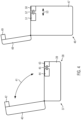
- the motorcycle frame 3 is provided with the steering head bearing receptacle 4 in the form of a steering head bearing tube 14 equipped with a steering head bearing 13, which will be described in more detail with reference to Fig. 2 can be seen in the drawing and with an in Fig. 1 only schematically shown handlebar locking device 15 is provided.
- This handlebar locking device 15 is designed in the form of a mechanical lock, which will be described below with reference to Fig. 2 The drawing will be explained in more detail.
- FIG. 2 The drawing shows a schematic representation of the handlebar 7 and an upper fork bridge 16 in the lower drawing, which accommodates the in Fig. 1 Telescopic spring fork 17, shown only schematically, with the two telescopic spring fork legs 18 is used, the telescopic spring fork 17 being pivotable around a pivot point 19 formed by the steering head bearing 14, as shown by arrow 20 Fig. 2 can be seen in the drawing.
- the steering head bearing receptacle 4 is arranged adjacent to the motorcycle frame 3 and includes the fork bridge 16, which, as shown in the upper illustration Fig. 2 As can be seen from the drawing, has a recess 21 into which a bolt 22 can engage, which can be displaced in the direction of the double arrow 24 by means of an electrically operated actuating device 23 in order to lock the handlebar locking device 15, as shown in the right half of the upper illustration the Fig. 2 can be seen in the drawing or to cancel the locking position of the handlebar locking device 15, as can be seen from the left half of the upper illustration Fig. 2 can be seen in the drawing.
- the control device 9 can monitor the actuation of the actuating device 23 and thus determine whether the handlebar locking device 15 is in the locked or unlocked position.
- the control device 9 can also control the actuating device 23 to move the bolt 22 in the direction of the double arrow 24, i.e. bring about the locking position of the handlebar locking device 15 and also cancel the locking position. In this way, the control device 9 can control this operating mode of the motorcycle 2.
- pivoting movement of the fork bridge 16 according to the arrow 20 is detected by a sensor in the form of, for example, a rotation angle sensor 25, so that the activation of the actuating device 23 for displacing the bolt 22 to bring about an engagement position of the bolt 22 with the recess 21 only takes place when an overlap of the bolt 22 with the recess 21 has been detected by the control device 9 by the rotation angle sensor 25.
- the control device 9 is therefore set up to activate the handlebar locking device 15 when the user of the system 1 has activated the switch unit 8 and in this way has informed the system 1 that it is, for example, for a driving break or after the end of the journey with the motorcycle 2 should be put into a rest mode, i.e. anti-theft measures should be taken, which, in addition to activating the immobilizer device 11, also include the activation of the handlebar locking device 15, i.e. the locking position of the bolt 22 in the recess 21 should be brought about.
- the user of the system according to the invention receives information on a display unit 26 in the form of, for example, a text message, to bring about the overlapping position of the bolt 22 with the recess 21 by the user controlling the steering angle of the handlebar 7 should increase in the direction to the left up to, for example, a stop position.
- This text message can also be followed by a further text message from the system 1 to the user, which confirms that the overlapping position has been successfully achieved.
- the motorcycle 2 in the illustrated embodiment with an internal combustion engine 6 as the drive unit 5 also has a fuel tank 27, which is equipped with a fuel tank 27 based on Fig. 3 the Tank cap 28 shown in the drawing can be closed.
- Fig. 3 The drawing shows the open position of the tank cap 28, so that fuel can be filled into the fuel tank 7 in the direction of the arrow 29.
- the user of the motorcycle 2 can move the fuel filler opening 30 by pivoting the tank cap 28 in the direction of the arrow 31 Fig. 3 release by the user actuating a flap 32 of the tank cap 28 and pivoting the tank cap 28 on the hinge 33 to bring about the open position.
- the tank cap 28 is secured via a schematically shown electrical actuating device 34 in that the actuating device 34 uses a bolt 35, shown only schematically, to bring about a Locking position of the bolt 35 with the tank cap 28 is actuated, so that the tank cap 28 cannot be opened.
- the control device 9 can actuate the actuating device 34 and the bolt 35 to bring about the locking position of the bolt 35 with the tank cap 28.
- the user wants to resume driving the motorcycle 2, the user presses a button 36 on the portable radio device 10, which results in the radio device 10 wirelessly sending corresponding authentication information to the control device 9 and then the control device 9 the actuating device 34 controlled, so that the bolt 35 is moved from the locking position with the tank cap 28 into an unlocked position and thus the tank cap 28 can be opened again via the flap 32.
- the actuation device 34 can therefore move the bolt 35 in the direction of the double arrow 36 in both directions.
- the control device 9 is set up to control the operating mode of the tank cap 28, that is to say to change the operating mode of the tank cap 28 so that it can be opened via the flap 32 or cannot be opened. If the user has activated the switch unit 8 to bring about the rest mode of the system 1 or the motorcycle 2, the control device 9 can control the actuating device 34 to bring about the locking position of the bolt 35 with the tank cap 28 and if the user of the system 1 or the motorcycle 2 has pressed the button 36 on the portable radio device 10 to resume driving the motorcycle 2 and the radio device 10 has then sent authentication information that the control device 9 then recognized as valid, the control device 9 can use the actuating device 34 to cancel the locking position of the bolt 35 control the tank cap 28.
- the control device 9 is therefore set up to control and monitor the operating mode of the system 1 with regard to the locking of the fuel filling opening 30 of the fuel tank 27.
- FIG. 4 The drawing shows a schematic representation of a luggage storage device 37 for the motorcycle 2 in the form of one in the left half of the drawing Fig. 4 shown top cases 38.
- the top cases 38 has a lower shell 39 and an upper shell 40, which can be pivoted relative to the lower shell 39 in the direction of the double arrow 41 in order to open or close the top case 38.
- a tab 42 of the upper shell 40 comes into an engagement position with a recess 43 in the lower shell 39 and can be operated via an electrical actuation device 44, which is only shown schematically a bolt 45 can be displaced by the actuating device 44 to bring about an engagement position between the bolt 45 and the tab 42 and thus the top case 38 can be locked against unauthorized intervention.
- the control device 9 is set up to control the electrical actuating device 44 to bring about a locking position between the bolt 45 and the tab 42 after a corresponding actuation of the switch unit 8 by the user.
- the control device 9 is also set up to cancel the locking position between the bolt 45 and the tab 42 when a user of the system 1 according to the invention or of the motorcycle 2 has pressed the button 36 on the portable radio device 10 and thus one of the control device 9 as has transmitted validly verified authentication information to the control device 9 and this then controls the actuating device 44 to cancel the locking position between the bolt 45 and the tab 42.
- the control device 9 is therefore set up to monitor and control the operating mode of locking the closure of the luggage storage device 37.
- the luggage storage device 37 was explained above using a top case 38.
- the motorcycle 2 according to the system 1 according to the invention can also have a luggage storage device instead of or in addition to the top case 38 Fig. 4
- the drawing also has a side case 46 shown in the right half of the drawing.
- the side case 46 has a lower shell 47 and an upper shell 48 pivotally articulated thereon, which at the same time forms the lid of the side case 46.
- the cover 48 has a tab 48 which comes to rest in a recess 50 of the side case 46 in a closed position of the side case 46. Similar to what was already described above for the top case 38, the side case 46 also has an electrically operable actuating device 51, by means of which a bolt 52 can be displaced in the direction of the double arrow 53 in such a way that the bolt 52 is in contact with the tab 49 Occupies the locking position or can be released from the locking position again.
- the control device 9 can control the actuating device 51 so that it moves the bolt 52 into the locking position with the tab 49 of the cover 48. If the locking position between the tab 49 and the bolt 52 is to be canceled, the control device 9 can move the bolt 52 out of the engagement position with the tab 49 via a corresponding control of the actuating device 51.
- the user of the system 1 according to the invention wants to put the motorcycle 2 in a park position or out of operation position, he can do this by actuating the switch unit 8, whereby the blocking information is simultaneously transmitted to the transportable radio device 10 and this is put into rest mode after the first time interval has elapsed.
- the actuation of the switch unit 8 also results in the control device 9 controlling the actuating device 51 to move the bolt 52 into the locking position of the bolt 52 with the tab 49.
- the actuation of the switch unit 8 also results in the control device 9 activating the immobilizer device 11, activating the handlebar locking device 15 and activating the locking of the tank cap 28 by moving the bolt 35 into the locking position with the tank cap.
- the actuation of the switch unit 8 also results in a corresponding message being issued to the user on the display unit 26 in the form of a text message, which informs the user that he has activated the sleep mode of the portable radio device 10 and, moreover, the anti-theft mechanisms or mechanisms to secure the motorcycle 2 or the system 1 against manipulation or theft by activating the immobilizer device and/or activating the handlebar locking device and/or locking the tank cap and/or locking the top case and/or the side case or other luggage storage devices and/or the seat assembly of the motorcycle is locked.
- the motorcycle 2 also has a seat arrangement 54, which is shown schematically in Fig. 1 is shown in the drawing and also schematically again in Fig. 5 shown in the drawing.
- the motorcycle 2 also has an electrically actuated actuating device 55, which is provided with a bolt 56 which can be moved by this and which has an in Fig. 5
- the frame component 57 of the motorcycle frame 3 shown schematically in the drawing can be brought into a releasable engagement.
- the seat 58 of the seat arrangement 54 can then no longer be opened and access to components or devices of the motorcycle 2 arranged under the seat 58, such as a fuse box, a luggage compartment or the like, is then no longer possible for unauthorized third parties.
- the can Control device 9 moves the actuating device 55 for displacing the bolt 56 from the engagement position with the frame component 57 into an unlocked position, so that the user again has unrestricted access to the devices of the motorcycle 2 arranged under the seat 58.
- the control device 9 is therefore also set up to monitor and control the operating mode of the system 1 or motorcycle 2 with regard to the locking position of the closure of the seat arrangement.
- the control device 9 no longer issues a start release for putting the drive unit 5 into operation and thus the drive unit can no longer be activated. If the user has deactivated the drive unit, for example switched off the internal combustion engine, but does not actuate the switch unit 8 to activate the sleep mode of the portable radio device 10 has, the user can still start and operate the internal combustion engine according to an embodiment of the system according to the invention, which is advantageous, for example, in the event of a longer stop in front of a traffic light system that blocks the vehicle from continuing its journey.
- FIG. 6 The drawing shows a flow chart to further explain the system according to the present invention.
- a step S1 the system 1 according to the invention monitors an activation of the request to put the portable radio device 10 into sleep mode.
- the system 1 can monitor an actuation of the switch unit 8 by the user of the motorcycle 2.
- the switch unit 8 When the switch unit 8 is actuated, the first time interval T1 starts, until the end of which the user can revoke any accidental actuation of the switch unit 8 and thus an activation of the sleep mode of the portable radio device 10 by further actuating the switch unit 8.
- this first time interval T1 can be changed by the user of the system, for example by changing the time interval accordingly by operating the display unit 26 on the motorcycle 2.
- the time interval T1 can be transmitted from the control device 9 to the transportable radio device 10 according to the system according to the invention. This can be done, for example, by a corresponding actuation of the switch unit 8 by the user of the motorcycle.
- the system 1 therefore enables the user to transmit the first time interval to the transportable radio device 10 via a corresponding activation of the control device 9, together with the transmission of the first time interval T1 to the transportable radio device 10 or before or after the transmission of the first Time interval T1 to the radio device 10, blocking information can be transmitted to the radio device 10, the transmission of this blocking information causing the transportable radio device 10 to go into sleep mode, in which the transportable radio device 10 no longer tries to establish a communication connection with the control device 9 , i.e. in particular no longer transmits any authentication information to the control device 9.
- the transportable radio device 10 automatically switches to a rest mode and in this rest mode the transportable radio device no longer responds to corresponding communication requests from the control device 9. In this rest mode, the portable radio device 10 no longer sends any authentication information to the control device 9, so that it can no longer be received by an unauthorized third party.
- the transportable radio device 10 can send acknowledgment of receipt information to the control device 9 after receiving the blocking information, which, for example, also serves as a confirmation of the activation of the sleep mode for the user of the system according to the invention as an acknowledgment of receipt can be displayed in the display unit 26 of the motorcycle 2.
- control device 9 can deactivate the ignition enable signal T15 of the motorcycle 2 and activate the immobilizer device 11.
- the control device 9 can also activate the handlebar locking device 15 of the motorcycle 2, as has already been explained above.
- the system 1 can, for example, via the display unit 26 of the motorcycle 2, also send a message to the user of the vehicle that he or she should increase the steering angle of the handlebar 7 so that there is an overlapping position between the bolt 22 of the handlebar locking device 15 and the recess 21 of the fork bridge 16 is brought about, which the system 1 according to the invention can monitor, for example via the rotation angle sensor 25, so that the system 1 automatically brings about the locking position of the bolt 22 with the recess 21 after determining that the overlapping position has been brought about and the ignition system of the vehicle has been deactivated can, which can also be communicated, for example, via a corresponding message to the user of the vehicle via the display unit 26.
- control device 9 can bring about the locking position of the tank cap 28 by controlling the actuating device 34 to move the bolt 35 into the locking position of the bolt 35 with the tank cap 28.
- the system 1 can also secure the luggage storage system of the motorcycle 2 in a next step S4 by the control device 9 controlling the actuating device 44 and/or 51 for displacing the bolt 45 and/or 52 in such a way that the respective bolt 45 and/or 52 with the respective tab 42 and / or 49 assumes a locking position and therefore unauthorized access to the top case 38 and / or the side case 46 is no longer possible.
- the control device 9 can also bring about a locking of the seat arrangement 54, as has already been explained above.
- the system according to the invention can also prevent the transmission of a release signal to the engine control unit 12 in a step S5, although this can also be done together with step S1 according to an alternative procedure.
- the system according to the invention can transmit the first time interval T1, which according to the present invention can, for example, include a time period of 1 second to 10 seconds inclusive, to the transportable radio device 10 in step S1, whereby in step S1 also time interval information can be transmitted to the portable radio device regarding the second time interval T2.
- This second time interval T2 which according to the present invention can, for example, include a time period of 5 seconds to 60 seconds inclusive, can also be transmitted from the control device 9 to the portable radio device 10 in step S1.
- This transmission of the second time interval T2 can take place, for example, before the transmission or after the transmission or together with the transmission of the blocking information to the transportable radio device 10.
- the time interval information relates to the first time interval T1 and / or of the second time interval T2 is transmitted from the control device 9 to the transportable radio device 10 with each transmission or with a certain number or selection of transmissions.
- the user of the system 1 according to the invention wants to return the motorcycle 2 to an activated state, for example to drive the motorcycle 2, the user presses the button 36 on the portable radio device 10, which results in the portable radio device 10 answering corresponding communication requests from the control device 9 to the portable radio device 10 and in particular also transmitting authentication information to the control device 9.
- a step S6 the receipt of the authentication information and its confirmation by the control device 9 as valid authentication information results in the control device 9 putting the drive unit 5 of the motorcycle 2 into drive readiness by sending release information to the engine control unit 12, so that the user can use the drive unit 5 can be put into operation, for example the internal combustion engine 6 can be started.
- the control device 9 can deactivate the immobilizer device 11 of the motorcycle and deactivate the handlebar locking device 15 of the motorcycle and also deactivate the locking of the tank cap 28 and deactivate the locking of the luggage storage device of the motorcycle, i.e. H. deactivate the locking of the top case and/or the locking of the side case and, in addition, the control device 9 can also allow the seat arrangement of the motorcycle to be opened again by deactivating the locking of the closure of the seat arrangement.
- the user can also change the time interval T2, for example by operating the motorcycle's display device, and adapt it to his needs, for example.
- the motorcycle is in the inoperative state with the anti-theft mechanisms activated in an environment where an unauthorized
- the user may prefer a longer period T2 than would be the case in an environment in which unauthorized access to the motorcycle by third parties is more likely.
- the portable radio device After the period T2 has elapsed, the portable radio device returns to the idle mode, in which communication with the control device 9 no longer takes place and the motorcycle 2 is thus placed back into the inoperative position by the control device 9, for example the immobilizer is activated again will be brought about and/or user-selectable operating modes of the motorcycle. If the user of the motorcycle puts the motorcycle into operation within the adjustable period T2, for example starts the internal combustion engine, the motorcycle is available for normal operation and the portable radio device does not enter sleep mode.
- the portable radio device was activated unintentionally after it had previously been deactivated and had entered sleep mode, i.e. the button 36 of the radio device 10 was actuated in an unintentional manner because the radio device was, for example, in a pocket of the user's motorcycle clothing and the radio device was activated in an unintentional manner by a movement of the user and this happened within range of the radio connection to the control device
- the second period T2 ensures that the wireless communication between the transportable radio device and the control device is interrupted again after the period T2 has expired and thus for third parties There is no possibility of logging authentication information wirelessly transmitted from the radio device to the control device and then using it for misuse purposes.
- the user can make changes to the reaction of the system 1 to the receipt of the authentication information after the portable radio device has been canceled by setting the system 1, for example via the display unit of the motorcycle.
- This option also increases comfort for the user, since the user can select which operating mode the motorcycle should adopt after receiving the authentication information.
- the user can therefore select whether the receipt of the authentication information and its confirmation by the control device as valid results in the drive unit being put into drive readiness and/or the immobilizer device of the motorcycle being deactivated and/or the handlebar locking device of the motorcycle being deactivated and/or the locking of the tank cap is deactivated and/or the locking of the closure of the luggage storage system is deactivated and/or the locking of the seat assembly is deactivated.
- the user can therefore adapt the operating modes of the motorcycle according to the needs that he expects from the motorcycle once he has activated the portable radio device and thus communicated to the system his desire to start or continue riding the motorcycle.
Landscapes
- Engineering & Computer Science (AREA)
- Mechanical Engineering (AREA)
- Computer Networks & Wireless Communication (AREA)
- Computer Security & Cryptography (AREA)
- Signal Processing (AREA)
- Physics & Mathematics (AREA)
- General Physics & Mathematics (AREA)
- Lock And Its Accessories (AREA)
Description
- Die vorliegende Erfindung betrifft ein System mit einem Motorrad und einer transportablen Funkvorrichtung, wobei das Motorrad einen Motorradrahmen mit einer Lenckopflageraufnahme und eine Antriebseinheit sowie eine Schaltereinheit und eine Steuervorrichtung aufweist und die Steuervorrichtung zur drahtlosen Kommunikation mit der Funkvorrichtung und zur Steuerung von Betriebsmodi des Motorrads in Abhängigkeit einer von der Funkvorrichtung zur Steuervorrichtung übertragenen Authentifizierungsinformation eingerichtet ist und die Steuervorrichtung zur drahtlosen Übertragung einer die Funkvorrichtung in einen Ruhemodus versetzenden Sperrinformation zur Funkvorrichtung eingerichtet ist, in dem eine Kommunikation der Funkvorrichtung an die Steuervorrichtung unterbleibt, nach dem Oberbegriff des Anspruchs 1.
- Bei dem Motorrad kann es sich um ein Straßenmotorrad oder auch um ein für die Fahrt im unwegsamen Gelände vorgesehenes Motorrad handeln oder auch um ein Geländesportmotorrad oder um ein zu anderen Zwecken vorgesehenes Motorrad.
- Die bei dem hier vorgesehenen Motorrad vorgesehene Antriebseinheit kann ein Verbrennungsmotor oder auch ein Elektromotor oder auch eine andere Antriebseinheit sein, welche vom Benutzer des Motorrads aus einem Betriebsmodus, bei dem die Antriebseinheit keine Antriebsleistung zur Verfügung stellt, in einen Betriebsmodus gesetzt werden kann, bei dem die Antriebseinheit Antriebsleistung zur Verfügung stellt.
- Bei einem Verbrennungsmotor wird diese hierzu von der Außerbetriebsstellung in die Betriebsstellung versetzt, der Verbrennungsmotor also gestartet, wozu vorher erforderlich ist, dass dem Zündungssystem des Verbrennungsmotors elektrische Energie zur Verfügung gestellt wird, wozu üblicherweise die Zündung in Betrieb gesetzt wird.
- Bei einem Elektromotor als Antriebseinheit wird dafür gesorgt, dass das Bordspannungssystem in die Betriebsstellung versetzt wird, sodass das Bordspannungssystem oder ein am Motorrad vorgesehenes Hochspannungssystem in einen zur Bereitstellung von elektrischer Antriebsenergie an den Elektromotor liefernden Betriebsmodus versetzt wird.
- Bislang war hierzu vorgesehen, dass der Benutzer des Motorrads einen Zündschlüssel, einen Schlüssel oder dergleichen in ein am Motorrad vorgesehenes Zündschloss steckt und gegebenenfalls betätigt und damit den Betriebsmodus herbeiführt, bei dem die Antriebseinheit in die Betriebsstellung versetzt wird.
- Es sind auch bereits schlüssellose, sogenannte Komfortzugangssysteme bekannt geworden, bei denen der Benutzer das Fahrzeug ohne dass Einstecken und entsprechende Drehen eines mechanischen Schlüssels in ein Zündschloss oder dergleichen in Betrieb nehmen kann.
- Bei einem solchen System ist üblicherweise eine Funkeinheit oder transportable Funkvorrichtung vorgesehen, die an eine am Motorrad vorgesehene Steuervorrichtung eine Authentifizierungsinformation sendet, sodass nur dann, wenn die von der Steuervorrichtung empfangene Authentifizierungsinformation von dieser als gültig überprüft wurde, der Betriebsmodus herbeigeführt werden kann, dem die Antriebseinheit Antriebsenergie bereitstellen kann, also beispielsweise der Benutzer des Motorrads den Verbrennungsmotor starten kann.
- Ein solches System weist für den Benutzer Komfortmerkmale auf, da es entfällt, dass der Benutzer einen Zündschlüssel handhaben muss, was bei einem Motorradfahrer als Benutzer von Vorteil ist, da dieser zur Handhabung des Zündschlüssels üblicherweise seine Handschuhe ausziehen muss, da die Handhabung des oftmals kleinen Zündschlüssels mit solchen Handschuhen umständlich und schwierig ist.
- Ein anderes Komfortmerkmal besteht beispielsweise darin, dass über am Motorrad vorgesehene Sensoreinrichtungen festgestellt werden kann, dass sich der Benutzer auf das Motorrad gesetzt hat oder seine Hände an die Lenkstange gelegt hat und somit ein vom Benutzer eingeleiteter Startvorgang des Verbrennungsmotors oder die Herbeiführung des Betriebsmodus der Antriebseinheit, bei der diese ganz allgemein Antriebsenergie bereitstellt, vom Komfortsystem als gültig identifiziert wird und vom System zugelassen wird.
- Ein solches schlüsselloses Komfortsystem arbeitet üblicherweise mit einer drahtlosen Funkkommunikation zwischen der Steuervorrichtung und der transportablen Funkvorrichtung, die den bekannten Zündschlüssel ersetzt.
- Bei einer solchen Kommunikation wird von der Steuervorrichtung an die transportable Funkvorrichtung eine Information übertragen und die Funkvorrichtung sendet eine Quittungsinformation oder Authentifizierungsinformation an die Steuervorrichtung.
- Solche Systeme sind daher anfällig für sogenannte Relayattacken, bei denen die Kommunikation zwischen der Steuervorrichtung und der transportablen Funkvorrichtung über vom Benutzer nicht autorisierte Systeme mitprotokolliert werden kann, sodass eine nicht autorisierte transportable Funkvorrichtung dann entsprechende nicht autorisierte Authentifizierungsinformationen an die Steuervorrichtung senden kann, und so ein Missbrauch des Systems aus Motorrad und transportabler Funkvorrichtung möglich ist.
- Anhand der
WO 2019/043021 A1 ist ein Motorrad mit einem schlüssellosen Komfortzugangssystem bekannt geworden, welches über am Motorrad vorgesehene Sensoren einzelne Handlungen des Benutzers des Motorrads erkennen kann. - Anhand der
EP 3470275 A1 ist ein drahtloses Kommunikationssystem für die Verwendung zwischen einem Fahrzeug und einer transportablen Funkvorrichtung bekannt geworden, welches dazu vorgesehen ist, die Gefahr von Relayattacken zwischen dem Fahrzeug und der transportablen Funkvorrichtung zu verringern, ohne den Benutzer mit Komforteinbußen zu belasten. -
DE 10 2016 112593 A1 offenbart ein Verfahren zum Betrieb eines Schließsystems für ein Kraftfahrzeug, tragbarer ID-Geber für ein Kraftfahrzeug und Schließsystem. - Ausgehend hiervon liegt der vorliegenden Erfindung die Aufgabe zugrunde, ein System mit einem Motorrad und einer transportablen Funkvorrichtung zu schaffen, welches die Sicherheit gegen einen unautorisierten Zugriff auf das System erhöht und die Gefahr des unautorisierten Abhörens der Kommunikation zwischen der Steuervorrichtung und der Funkvorrichtung verringert, ohne für den Benutzer des Systems Komforteinbußen zu schaffen.
- Die Erfindung weist zur Lösung dieser Aufgabe die im Anspruch 1 angegebenen Merkmale auf. Vorteilhafte Ausgestaltungen hiervon sind in den weiteren Ansprüchen beschrieben.
- Die Erfindung schafft ein System mit einem Motorrad und einer transportablen Funkvorrichtung, wobei das Motorrad einen Motorradrahmen mit einer Lenkkopflageraufnahme und eine Antriebseinheit sowie eine Schaltereinheit und eine Steuervorrichtung aufweist und die Steuervorrichtung zur drahtlosen Kommunikation mit der Funkvorrichtung und zur Steuerung von Betriebsmodi des Motorrads in Abhängigkeit einer von der Funkvorrichtung zur Steuervorrichtung übertragenen Authentifizierungsinformation eingerichtet ist und die Steuervorrichtung zur drahtlosen Übertragung einer die Funkvorrichtung in einen Ruhemodus versetzenden Sperrinformation zur Funkvorrichtung eingerichtet ist, in dem eine Kommunikation der Funkvorrichtung an die Steuervorrichtung unterbleibt, wobei die Steuervorrichtung zur drahtlosen Übertragung einer ersten und/oder zweiten Zeitintervallinformation betreffend die Länge eines ersten und/oder zweiten Zeitintervalls an die Funkvorrichtung eingerichtet ist, nach deren Ablauf die Funkvorrichtung den Ruhemodus einnimmt, sich also beispielsweise in den Ruhemodus versetzt.
- Das nach dem erfindungsgemäßen System vorgesehene Motorrad weist also einen Motorradrahmen mit einer Lenkkopflageraufnahme auf sowie eine Antriebseinheit und eine Schaltereinheit und eine Steuervorrichtung. Die Schaltereinheit ist dafür vorgesehen, mittels einer Betätigung der Schaltereinheit Aktionen am Motorrad auszulösen, wie beispielsweise die Steuervorrichtung zur drahtlosen Kommunikation mit der transportablen Funkvorrichtung anzusteuern, oder verschiedene Betriebsmodi des Motorrads zu aktivieren.
- Bei den Betriebsmodi des Motorrads kann es sich beispielsweise um das Einschalten des Zündungssystems der Antriebseinheit des Motorrads handeln, also beispielsweise das Motorrad in einen solchen Betriebszustand zu versetzen, dass eine elektrische Startvorrichtung einer Brennkraftmaschine des Motorrads aktiviert werden kann, also mit einem Startstrom aus dem Bordspannungsnetz versorgt werden kann oder dass ganz allgemein die Zündung freigegeben werden kann.
- Ein weiterer Betriebsmodus, der von der Steuervorrichtung gesteuert werden kann, ist die Aktivierung und/oder Deaktivierung einer Lenkersperreinrichtung des Motorrads, die Aktivierung und/oder Deaktivierung einer Wegfahrsperreinrichtung des Motorrads, die Verriegelung und/oder Entriegelung eines Tankdeckels, welcher eine Kraftstoffeinfüllöffnung eines Kraftstofftanks des Motorrads verschließt oder freigibt, die Aktivierung und/oder Deaktivierung der Verriegelung eines Verschlusses einer Gepäckaufbewahrungseinrichtung des Motorrads, die Aktivierung und/oder Deaktivierung einer Verriegelung eines Verschlusses einer Sitzbankanordnung des Motorrads, die Aktivierung und/oder Deaktivierung einer Steuervorrichtung zur Inbetriebnahme der Antriebseinheit des Motorrads, um nur einige Beispiele in dieser nicht abschließenden Aufzählung zu nennen.
- Mit der Schaltereinheit, die am Motorrad vorgesehen ist und hierzu beispielsweise an einer Steuereinrichtung des Motorrads in der Form der Lenkstange vorgesehen sein kann, können also Steuerbefehle oder Steuersequenzen an die Steuervorrichtung des Motorrads übertragen werden, sodass diese dann einzelne Betriebsmodi des Motorrads ansteuert, also aktiviert oder deaktiviert.
- So ist es beispielsweise auch vorgesehen, dass eine Betätigung der Schaltereinheit dazu führt, dass das Zündungssystem des Motorrads deaktiviert wird, die Zündung einer als Verbrennungsmotor vorgesehenen Antriebseinheit des Motorrads also ausgeschaltet wird und somit der Verbrennungsmotor nicht mehr gestartet werden kann.
- Mit dieser Deaktivierung des Zündungssystems der Antriebseinheit ist auch umfasst, dass ein Elektromotor, der als Antriebseinheit beim Motorrad vorgesehen ist, deaktiviert wird, also keine Antriebsleistung mehr zur Verfügung stellen kann, wozu er beispielsweise von dem am Motorrad zum Betrieb des Elektromotors vorgesehenen Hochspannungssystem getrennt wird.
- Die Deaktivierung des Zündungssystems findet also dann statt, wenn ein Benutzer des Motorrads die Schaltereinheit betätigt, und durch diese Betätigung der Schaltereinheit wird die Steuervorrichtung auch dahingehend betätigt, dass diese eine Zeitinformation an die transportable Funkeinheit oder Funkvorrichtung überträgt und zwar eine Zeitinformation bezüglich eines ersten und/oder Zeitintervalls, die die Länge eines ersten und/oder zweiten Zeitintervalls umfasst, nach deren Ablauf die Funkvorrichtung den Ruhemodus einnimmt und somit keine Funkkommunikation von der Funkvorrichtung an die Steuervorrichtung mehr stattfindet und somit auch keine in dieser Funkkommunikation ansonsten enthaltene Authentifizierungsinformation mehr an die Steuervorrichtung übertragen wird und somit auch nicht mehr mittels eines nicht autorisierten Empfangsgerät, welches zu Relayattacken eingesetzt werden kann, abgefangen werden kann.
- Die Betätigung der Schaltereinheit führt also dazu, dass die Funkvorrichtung eine konstante oder veränderbare oder am Motorrad einstellbare Zeitintervallinformation übertragen erhält, nach deren Ablauf sich die Funkvorrichtung automatisch in den Ruhemodus versetzt.
- Bei dieser Zeitintervallinformation kann es sich um eine erste Zeitintervallinformation handeln, die von der Funkvorrichtung auswertbare Dateninformation umfasst, sodass sich die Funkvorrichtung nach Ablauf des ersten Zeitintervalls selbsttätig in den Ruhemodus versetzt, also keine Kommunikation mehr mit der Steuervorrichtung aufbaut.
- Dieses erste Zeitintervall kann dazu genutzt werden, die automatische Deaktivierung der transportablen Funkvorrichtung nach Ablauf des ersten Zeitintervalls zu deaktivieren, wenn der Benutzer des Motorrads innerhalb des ersten Zeitintervalls feststellt, dass er den Befehl zur Deaktivierung der transportablen Funkvorrichtung versehentlich ausgelöst hat, was beispielsweise dann geschieht, wenn der Benutzer die Schaltereinheit versehentlich berührt hat, was bei einem Betrieb des Motorrads durch einen beispielsweise Motorradhandschuhe tragenden Benutzer in der Praxis durchaus geschehen kann.
- Da die Reaktivierung einer zum Schutz gegen Relayattacken deaktivierten transportablen Funkvorrichtung eine andere Betätigung als die Betätigung der am Motorrad vorgesehenen Schaltereinheit voraussetzt, nämlich beispielsweise eine Aktivierung der als Funkschlüssel ausgebildeten transportablen Funkvorrichtung, und diese zu diesem Zweck vom Benutzer separat gehandhabt werden muss, indem der Benutzer eine Schaltereinheit an der transportablen Funkvorrichtung betätigt, ist die Möglichkeit des Widerrufs des versehentlichen Auslösens der Deaktivierung der transportablen Funkvorrichtung für den Benutzer des Motorrads von Vorteil und ein Zugewinn an Komfort, indem beispielsweise eine erneute Betätigung der Schaltereinheit innerhalb des ersten Zeitintervalls die automatische Deaktivierung der transportablen Funkvorrichtung unterbindet.
- Es ist hierzu vorgesehen, dass der Benutzer des Motorrads nach der versehentlichen oder auch beabsichtigten Betätigung der Schaltereinheit, die zu einer automatischen Deaktivierung der transportablen Funkvorrichtung führen würde, eine Information in der Form beispielsweise einer visuellen oder akustischen Information über die Betätigung der Schaltereinheit an einer Displayeinheit oder Akustikeinheit des Motorrads erhält, sodass dem Benutzer die Möglichkeit gegeben wird, über eine erneute Betätigung der Schaltereinheit die Deaktivierung der transportablen Funkvorrichtung zu unterbinden.
- Über diese visuelle und/oder akustische Information erfährt der Benutzer des Motorrads darüber hinaus eine Bestätigung oder Quittung der Aktivierung der Schaltereinheit des Motorrads, sodass er in die Lage versetzt wird, seine Entscheidung über die beabsichtigte Aktivierung des Ruhemodus der transportablen Funkvorrichtung zu widerrufen beziehungsweise die unbeabsichtigte Aktivierung des Ruhemodus aufzuheben, bevor die transportablen Funkvorrichtung in den tatsächlichen Ruhemodus eintritt.
- In dem Ruhemodus reagiert dann die transportable Funkvorrichtung nicht mehr auf von der Steuervorrichtung an die Funkvorrichtung drahtlos übermittelte Anfragen, sodass auch keine Möglichkeit mehr besteht, die Kommunikation zwischen der Funkvorrichtung und der Steuervorrichtung unautorisiert mit zu protokollieren.
- Wie es vorstehend bereits erwähnt wurde, ist das System dazu in der Lage, neben der ersten Zeitintervallinformation alternativ oder zusätzlich eine zweite Zeitintervallinformation an die Funkvorrichtung zu übertragen, welche eine Information bezüglich eines zweiten Zeitintervalls umfasst, nach dessen Ablauf sich die Funkvorrichtung in den Ruhemodus versetzt.
- Wenn die transportable Funkvorrichtung wieder in den Modus der Kommunikation mit der Steuervorrichtung versetzt werden soll, ist es vorgesehen, dass der Benutzer den Funkschlüssel beziehungsweise die transportable Funkvorrichtung mittels eines Tastendrucks oder einer anderen Betätigung der transportablen Funkvorrichtung aktiviert, sodass der Funkschlüssel auf entsprechende Anfragen der Steuervorrichtung an den Transponder der transportablen Funkvorrichtung antwortet.
- Dieses zweite Zeitintervall, während dessen die Kommunikation zwischen der transportablen Funkvorrichtung und der Steuervorrichtung wieder aufgenommen ist, kann nach der Erfindung einstellbar festgelegt werden und dient der Sicherheitserhöhung in der Kommunikation zwischen der transportablen Funkvorrichtung und der Steuervorrichtung.
- Wenn nämlich das zweite Zeitintervall abgelaufen ist, ohne dass eine entsprechende Aktion des Benutzers am Motorrad vorgenommen wurde, versetzt sich die transportable Funkvorrichtung automatisch wieder in den Ruhemodus und unterbricht somit die Kommunikation mit der Steuervorrichtung.
- Wenn der Benutzer des Motorrads nach dem erfindungsgemäß vorgesehenen System die transportable Funkvorrichtung in den Aktivmodus versetzt und diese ein Signal oder Signale an die Steuervorrichtung über die Aktivierung versandt hat, kann die erfindungsgemäße vorgesehene Steuervorrichtung einen einzelnen Betriebsmodus oder mehr als einen Betriebsmodus oder mehrere Betriebsmodi des Motorrads aktivieren, also beispielsweise das Motorrad startklar machen, indem das Zündungssignal T15 freigegeben wird und/oder eine Wegfahrsperre des Motorrads deaktiviert wird und oder eine Lenkersperreinrichtung des Motorrads freigegeben wird und/oder eine Verriegelung eines Tankdeckels eines Kraftstofftanks des Motorrads freigegeben wird und/oder eine Verriegelung eines am Motorrad angeordneten Topcases und/oder am Motorrad vorgesehenes Seitenkoffers freigegeben wird und/oder eine Verriegelungseinrichtung einer Sitzbankanordnung des Motorrads freigegeben wird und/oder die Steuervorrichtung als Main Unit eine Freigabe für den Motorstart erteilt.
- Damit wird ein erheblicher Komfortgewinn für den Benutzer des Motorrads erreicht, da alle oder wenigstens die wesentlichen Betriebsmodi des Motorrads, die für den normalen Betrieb des Motorrads vorgesehen sind, mittels eines einzigen Tastendrucks oder einer einzelnen Betätigung am Funkschlüssel durch den Benutzer des Fahrers aktiviert werden können, ohne dass es eines weiteren Eingriffs des Fahrers am Motorrad bedürfte.
- Es ist nach der Erfindung vorgesehen, dass der Benutzer des Motorrads die Aktivierung und/oder Deaktivierung einzelner Betriebsmodi des Motorrads beispielsweise über eine Displayeinheit konfigurieren kann und der Benutzer so Einfluss darauf hat, wie das Motorrad nach einer entsprechenden Aktivierung durch die Betätigung des Funkschlüssels reagiert.
- Der Funkschlüssel beziehungsweise die transportable Funkvorrichtung wird vom Benutzer des Motorrads mit sich geführt, also üblicherweise beispielsweise in der Praxis in einer Jackentasche oder Hosentasche der Motorradbekleidung des Benutzers verwahrt.
- Da ein solcher Verwahrort die nicht auszuschließende Möglichkeit einer unvorhergesehenen, nicht beabsichtigten Fehlbedienung des Schlüssels mit sich bringt, der Benutzer kann den Funkschlüssel beispielsweise unbeabsichtigt bei einem Griff in die Jackentasche aktivieren, in der sich der Funkschlüssel befindet, und der Funkschlüssel kann dann im Abstand zum Motorrad, bei dem der Benutzer des Motorrads dieses nicht im Blick hat, eine Authentifizierungsinformation an die Steuervorrichtung senden, obwohl dies vom Benutzer nicht gewünscht ist, versetzt sich die Funkvorrichtung nach Ablauf dieses einstellbaren zweiten Zeitintervalls automatisch wieder in den Ruhemodus, in dem eine Kommunikation der Funkvorrichtung mit der Steuervorrichtung unterbunden ist, und die Steuervorrichtung sorgt dafür, dass die für den normalen Betrieb des Motorrads benötigten Betriebsmodi wieder aufgehoben werden, also beispielsweise die Zündung ausgeschaltet wird und/oder die Wegfahrsperre aktiviert wird und/oder die Lenkersperreinrichtung aktiviert wird und/oder die Tankdeckelverriegelung aktiviert wird und/oder die Verriegelungseinrichtung am Topcase und einem oder beiden Seitenkoffern aktiviert wird und/oder die Verriegelungseinrichtung der Sitzbankanordnung aktiviert wird und/oder das Freigabesignal für den Motorstart durch die ECU oder der Steuervorrichtung aufgehoben wird.
- Damit stellt das erfindungsgemäße System für den Benutzer des Motorrads nicht nur deutlich mehr Komfortmerkmale zur Verfügung als dies bei bekannten Systemen der Fall ist, sondern erhöht auch die Sicherheit des Systems gegen Fehlbedienungen und/oder Missbrauch durch Relayattacken oder Diebstahl.
- Es ist nach einer Weiterbildung der Erfindung auch vorgesehen, dass die Steuervorrichtung zur gleichzeitigen oder konsekutiven Übertragung der Sperrinformation und der ersten und/oder zweiten Zeitintervallinformation an die Funkvorrichtung eingerichtet ist.
- Damit kann das erfindungsgemäße System mit der ersten und/oder zweiten Zeitintervallinformation auch gleichzeitig die Sperrinformation an die transportable Funkvorrichtung übertragen, also bei einer Betätigung der Schaltereinheit durch den Benutzer des Motorrads entweder nur die erste und/oder zweite Zeitintervallinformation an die Funkvorrichtung übertragen oder auch eine beliebige Kombination aus der Sperrinformation und/oder ersten Zeitintervallinformation und/oder zweiten Zeitintervallinformation und zwar gleichzeitig oder nacheinander oder beispielsweise auch zwei der drei Informationen simultan und die dritte Information dann infolge der ersten Übertragung.
- Es ist nach der erfindungsgemäßen System auch vorgesehen, dass die erste und/oder zweite Zeitintervallinformation nur dann zusammen mit der Sperrinformation oder vor der Sperrinformation oder nach der Sperrinformation übertragen wird, wenn an der ersten und/oder zweiten Zeitintervallinformation Änderungen durch den Benutzer des erfindungsgemäßen Systems vorgenommen worden sind, also beispielsweise das erste Zeitintervall und/oder zweite Zeitintervall durch den Benutzer des Systems geändert wurde.
- Es ist nach einer Weiterbildung der Erfindung auch vorgesehen, dass das Motorrad dazu eingerichtet ist, die Steuervorrichtung in Folge einer Betätigung der Schaltereinheit zur drahtlosen Übertragung der Sperrinformation und/oder der Zeitintervallinformation anzusteuern. Dadurch kann der Benutzer des erfindungsgemäßen Systems durch eine einfache Betätigung der Schaltereinheit den Ruhemodus der transportablen Funkvorrichtung aktivieren, ohne dass eine komplexe Aktivierung des Ruhemodus beispielsweise über eine Tasteneingabe an einem zentralen Bediendisplay des Motorrads notwendig wäre.
- Durch eine solche einfache Betätigung der Schaltereinheit kann der Benutzer des Motorrads nach dem System auch Betriebsmodi des Motorrads aktivieren, die beim Abstellen des Motorrads während einer Fahrpause oder nach Beendigung der Fahrstrecke normalerweise manuell vorgenommen werden, wie beispielsweise die Verriegelung der Lenkersperre, die Verriegelung des Tankdeckels, die Verriegelung der Gepäcktransporteinrichtungen am Motorrad, wie beispielsweise eines Topcases oder der Seitenkoffer oder andere Betriebsmodi. Der Benutzer erfährt daher nach einer Aktivierung der Schaltereinheit über eine Displayeinheit am Motorrad eine optische Rückmeldung oder auch eine akustische Rückmeldung und weiß, dass nach dem Ablauf des ersten Zeitintervalls die Funkvorrichtung automatisch in den Ruhemodus wechselt und die Steuervorrichtung am Motorrad die von Benutzer einstellbar ausgewählten Betriebsmodi des Motorrads ansteuert.
- Es ist dabei zur weiteren Komforterhöhung für den Benutzer des erfindungsgemäßen Systems vorgesehen, dass die Steuervorrichtung zur veränderbaren Einstellung der ersten und/oder zweiten Zeitintervallinformation eingerichtet ist, sodass der Benutzer über einen einfache Bedienung beispielsweise an der Displayeinheit des Motorrads das erste und/oder zweite Zeitintervall verändern kann, beispielsweise gemäß dem Benutzer im normalen Betrieb des Motorrads geläufiger Routinen bei der Inbetriebnahme des Motorrads oder dem Abstellen des Motorrads nach dessen Benutzung.
- Es ist nach einer Weiterbildung der Erfindung auch vorgesehen, dass die Steuervorrichtung zum drahtlosen Empfang einer von der Funkvorrichtung nach dem Empfang der Sperrinformation und/oder ersten und/oder zweiten Zeitintervallinformation übertragenen Empfangsquittungsinformation an die Steuervorrichtung eingerichtet ist.
- Diese Weiterbildung des erfindungsgemäßen Systems sorgt dafür, dass die Steuervorrichtung eine Rückmeldung von der Funkvorrichtung über den bestimmungsgemäßen Empfang der von der Steuervorrichtung übersandten Informationen erhält. Es kann nach dem erfindungsgemäßen System auch vorgesehen sein, dass der Benutzer des Systems eine entsprechende Bestätigung in der Displayeinheit des Motorrads erfährt und es kann nach der Erfindung auch vorgesehen sein, dass der Benutzer auch eine Fehlermeldung in der Displayeinheit erhält, wenn diese Empfangsquittungsinformation von der Steuervorrichtung nicht ordnungsgemäß empfangen wurde, wobei es hierzu auch vorgesehen ist, dass eine solche Fehlermeldung erst nach einer weiteren Übertragung der Sperrinformation und/oder ersten und/oder zweiten Zeitintervallinformation an die transportable Funkvorrichtung erhält, die ohne bestimmungsgemäßen Empfang der Empfangsquittungsinformation durch die Steuervorrichtung erfolgte.
- Nach Erhalt der Empfangsquittungsinformation durch die Steuervorrichtung kann diese die vorstehend erwähnten Betriebsmodi am Motorrad ansteuern, sodass beispielsweise die Lenkersperre verriegelt wird und somit das Motorrad gegen Diebstahl gut geschützt ist, da ein einfaches Wegschieben des so gesicherten Motorrads nicht mehr möglich ist.
- Dies dient der weiteren Sicherheitserhöhung des Systems, da der Benutzer hiermit eine Information von System erhält, die ihn darüber informiert, dass die Funkübertragung von der Steuervorrichtung zur transportablen Funkvorrichtung beispielsweise durch ein Störsignal gezielt gestört wurde und daher der Benutzer sensibilisiert wurde dafür, dass er den Vorgang der Außerbetriebsstellung des Motorrads durch beispielsweise Verriegelung der Lenkersperre manuell durchführen muss.
- Es ist nach einer Weiterbildung der Erfindung auch vorgesehen, dass die Funkvorrichtung zum Verlassen des Ruhemodus und zur drahtlosen Übertragung der Authentifizierungsinformation in Folge einer die Aktivierung der Funkvorrichtung auslösenden Betätigung der Funkvorrichtung durch einen Benutzer der Funkvorrichtung eingerichtet ist.
- Somit kann der Benutzer die Funkvorrichtung aus dem Ruhemodus in den Aktivmodus umschalten, indem er eine einfache Betätigung einer Drucktaste oder dergleichen an der Funkvorrichtung durchführt und so dafür sorgt, dass die Kommunikation von der Funkvorrichtung zur Steuervorrichtung wieder initiiert wurde und somit die am Motorrad vorgesehene Steuervorrichtung das Motorrad in den Betriebsmodus "Betrieb" versetzen kann, also beispielsweise die Lenkersperreinrichtung entriegeln kann, die Wegfahrsperre deaktivieren kann, die Tankdeckelverriegelung freigeben kann, die Verriegelung der Gepäcktransporteinrichtungen am Motorrad aufheben kann und die Freigabe für den Motorstart erteilen kann.
- Es ist nach einer Weiterbildung der Erfindung auch vorgesehen, dass die Steuervorrichtung zur drahtlosen Übertragung einer Betriebsmodusinformation an die Funkvorrichtung eingerichtet ist, nach deren Empfang die Funkvorrichtung in einem die Kommunikation mit der Steuervorrichtung aufrechterhaltenden Kommunikationsmodus verbleibt.
- Diese Weiterbildung besitzt beispielsweise den Vorteil, dass die Funkvorrichtung in einen Kommunikationsmodus mit der Steuervorrichtung geschaltet werden kann, der andere Dateninformationen beinhaltet als die vorstehend erwähnten Authentifizierungsinformationen, sodass es unberechtigten Dritten schwieriger gemacht wird, die Authentifizierungsinformationen während eines normalen Betriebs des Systems in Erfahrung zu bringen.
- Es ist nach einer Weiterbildung der Erfindung auch vorgesehen, dass die Steuervorrichtung zur drahtlosen Übertragung einer Betriebsmodusinformation an die Funkvorrichtung innerhalb des zweiten Zeitintervalls eingerichtet ist, nach deren Empfang die Funkvorrichtung in einem die Kommunikation mit der Steuervorrichtung aufrechterhaltenden Kommunikationsmodus verbleibt.
- Diese Weiterbildung des Systems nach der Erfindung weist den Vorteil auf, dass die Betriebsmodusinformation an die Funkvorrichtung nur innerhalb eines zeitlich eng begrenzten Zeitintervalls übertragen wird, nämlich innerhalb des zweiten Zeitintervalls, sodass eine fortlaufende Übertragung der Betriebsmodusinformation an die Funkvorrichtung unterbleibt und somit der einen Missbrauch ermöglichende Daten- und Informationsaustausch zwischen der Steuervorrichtung und der transportablen Funkvorrichtung beschränkt wird.
- Es ist nach einer Weiterbildung des erfindungsgemäßen Systems auch vorgesehen, dass das Motorrad eine Wegfahrsperreinrichtung aufweist, welches die Antriebseinheit des Motorrads in einen Betriebszustand versetzt, in dem eine Fortbewegung des Motorrads mit einer von der Antriebseinheit bereit gestellten Antriebsenergie unterbunden ist.
- Die Aktivierung oder Deaktivierung der Wegfahrsperreinrichtung des Motorrads sind Betriebsmodi, welche die Steuervorrichtung unter anderem in Abhängigkeit der Kommunikation mit der transportablen Funkvorrichtung durchführen kann.
- Der Benutzer des erfindungsgemäßen Systems kann die Schaltereinheit am Motorrad betätigen, sodass die Sperrinformation und/oder Zeitintervallinformation an die transportable Funkvorrichtung übertragen wird.
- Nach Ablauf des ersten Zeitintervalls, während dessen der Benutzer des Systems die Aktivierung des Ruhemodus der Funkvorrichtung widerrufen kann, kann die Steuervorrichtung die Wegfahrsperreinrichtung des Motorrads automatisch aktivieren, sodass die von der Wegfahrsperreinrichtung bereitgestellte Diebstahlsicherung automatisch aktiviert wird. Alternativ hierzu ist es nach dem erfindungsgemäßen System auch vorgesehen, dass schon die Betätigung der Schaltereinheit durch den Benutzer die Wegfahrsperreinrichtung aktiviert und eine etwaige nochmalige Betätigung der Schaltereinheit durch den Benutzer innerhalb des ersten Zeitintervalls die Wegfahrsperreinrichtung wieder deaktiviert.
- Wenn der Benutzer dann die transportable Funkvorrichtung wieder aktiviert und eine Authentifizierungsinformation an die Steuervorrichtung übertragen hat, kann die Steuervorrichtung die Wegfahrsperreinrichtung deaktivieren, sodass das Motorrad hinsichtlich der Wegfahrsperreinrichtung betriebsbereit wird.
- Es ist nach einer Weiterbildung der Erfindung auch vorgesehen, dass das Motorrad eine Lenkersperreinrichtung aufweist, die mit einem fernsteuerbaren, insbesondere elektrisch betätigt verriegelbaren und entriegelbaren Bolzen versehen ist, der mit einer Ausnehmung der Lenkkopflageraufnahme in eine lösbare Eingriffsstellung bringbar ist und die Steuervorrichtung zur Überwachung der Eingriffsstellung eingerichtet ist.
- Die Aktivierung oder Deaktivierung der Lenkersperreinrichtung des Motorrads sind Betriebsmodi, welche die Steuervorrichtung unter anderem in Abhängigkeit der Kommunikation mit der transportablen Funkvorrichtung durchführen kann.
- Der Benutzer des erfindungsgemäßen Systems kann die Schaltereinheit am Motorrad betätigen, sodass die Sperrinformation und/oder Zeitintervallinformation an die transportable Funkvorrichtung übertragen wird.
- Nach Ablauf des ersten Zeitintervalls, während dessen der Benutzer des Systems die Aktivierung des Ruhemodus der Funkvorrichtung widerrufen kann, kann die Steuervorrichtung die Lenkersperreinrichtung des Motorrads automatisch aktivieren, sodass die von der Lenkersperreinrichtung bereitgestellte Diebstahlsicherung automatisch aktiviert wird. Alternativ hierzu ist es nach dem erfindungsgemäßen System auch vorgesehen, dass schon die Betätigung der Schaltereinheit durch den Benutzer die Lenkersperreinrichtung aktiviert und eine etwaige nochmalige Betätigung der Schaltereinheit durch den Benutzer innerhalb des ersten Zeitintervalls die Lenkersperreinrichtung wieder deaktiviert.
- Wenn der Benutzer dann die transportable Funkvorrichtung wieder aktiviert und eine Authentifizierungsinformation an die Steuervorrichtung übertragen hat, kann die Steuervorrichtung die Lenkersperreinrichtung deaktivieren, sodass das Motorrad hinsichtlich der Lenkersperreinrichtung betriebsbereit wird.
- Es ist nach einer Weiterbildung der Erfindung auch vorgesehen, dass das Motorrad einen Kraftstofftank mit einer Kraftstoffeinfüllöffnung und mit einer die Kraftstoffeinfüllöffnung lösbar verschließenden Tankdeckelanordnung aufweist und die Tankdeckelanordnung mit einem fernsteuerbaren, insbesondere elektrisch betätigt verriegelbaren und entriegelbaren Bolzen versehen ist, der mit einer Ausnehmung des Kraftstofftanks in eine lösbare Eingriffsstellung bringbar ist und die Steuervorrichtung zur Überwachung der Eingriffsstellung eingerichtet ist.
- Die Aktivierung oder Deaktivierung der Verriegelung der Tankdeckelanordnung des Motorrads sind Betriebsmodi, welche die Steuervorrichtung unter anderem in Abhängigkeit der Kommunikation mit der transportablen Funkvorrichtung durchführen kann.
- Der Benutzer des erfindungsgemäßen Systems kann die Schaltereinheit am Motorrad betätigen, sodass die Sperrinformation und/oder Zeitintervallinformation an die transportable Funkvorrichtung übertragen wird.
- Nach Ablauf des ersten Zeitintervalls, während dessen der Benutzer des Systems die Aktivierung des Ruhemodus der Funkvorrichtung widerrufen kann, kann die Steuervorrichtung die Verriegelung der Tankdeckelanordnung des Motorrads automatisch aktivieren, sodass die von der verriegelten Tankdeckelanordnung bereitgestellte Diebstahlsicherung automatisch aktiviert wird. Alternativ hierzu ist es nach dem erfindungsgemäßen System auch vorgesehen, dass schon die Betätigung der Schaltereinheit durch den Benutzer die Verriegelung der Tankdeckelanordnung aktiviert und eine etwaige nochmalige Betätigung der Schaltereinheit durch den Benutzer innerhalb des ersten Zeitintervalls die Verriegelung der Tankdeckelanordnung wieder deaktiviert.
- Wenn der Benutzer dann die transportable Funkvorrichtung wieder aktiviert und eine Authentifizierungsinformation an die Steuervorrichtung übertragen hat, kann die Steuervorrichtung die Verriegelung der Tankdeckelanordnung deaktivieren, sodass das Motorrad hinsichtlich der Tankdeckelanordnung betriebsbereit wird.
- Es ist nach einer Weiterbildung der Erfindung auch vorgesehen, dass das Motorrad eine Gepäckaufbewahrungseinrichtung aufweist, welche mit einem mit einer lösbaren verriegelbar ausgebildeten Verschlusseinrichtung versehen ist, die mit einem fernsteuerbaren, insbesondere elektrisch betätigt verriegelbaren und entriegelbaren Bolzen versehen ist, der mit einer Ausnehmung der Verschlusseinrichtung in eine lösbare Eingriffsstellung bringbar ist und die Steuervorrichtung zur Überwachung der Eingriffsstellung eingerichtet ist.
- Die Aktivierung oder Deaktivierung der der Verriegelung der Gepäckaufbewahrungseinrichtung des Motorrads sind Betriebsmodi, welche die Steuervorrichtung unter anderem in Abhängigkeit der Kommunikation mit der transportablen Funkvorrichtung durchführen kann.
- Nach Ablauf des ersten Zeitintervalls, während dessen der Benutzer des Systems die Aktivierung des Ruhemodus der Funkvorrichtung widerrufen kann, kann die Steuervorrichtung die Verriegelung der Gepäckaufbewahrungseinrichtung des Motorrads automatisch aktivieren, sodass die von der verriegelten Gepäckaufbewahrungseinrichtung bereitgestellte Diebstahlsicherung automatisch aktiviert wird. Alternativ hierzu ist es nach dem erfindungsgemäßen System auch vorgesehen, dass schon die Betätigung der Schaltereinheit durch den Benutzer die Verriegelung der Gepäckaufbewahrungseinrichtung aktiviert und eine etwaige nochmalige Betätigung der Schaltereinheit durch den Benutzer innerhalb des ersten Zeitintervalls die Verriegelung der Gepäckaufbewahrungseinrichtung wieder deaktiviert.
- Wenn der Benutzer dann die transportable Funkvorrichtung wieder aktiviert und eine Authentifizierungsinformation an die Steuervorrichtung übertragen hat, kann die Steuervorrichtung die Verriegelung der Gepäckaufbewahrungseinrichtung deaktivieren, sodass das Motorrad hinsichtlich der Gepäckaufbewahrungseinrichtung betriebsbereit wird.
- Es ist nach einer Weiterbildung der Erfindung auch vorgesehen, dass das Motorrad mit einer Sitzbankanordnung versehen ist, welche mit einem fernsteuerbaren, insbesondere elektrisch betätigt verriegelbaren und entriegelbaren Bolzen versehen ist, der mit einer am Motorradrahmen angeordneten Ausnehmung in eine lösbare Eingriffsstellung bringbar ist und die Steuervorrichtung zur Überwachung der Eingriffsstellung eingerichtet ist.
- Die Aktivierung oder Deaktivierung der der Verriegelung der Sitzbankanordnung des Motorrads sind Betriebsmodi, welche die Steuervorrichtung unter anderem in Abhängigkeit der Kommunikation mit der transportablen Funkvorrichtung durchführen kann.
- Der Benutzer des erfindungsgemäßen Systems kann die Schaltereinheit am Motorrad betätigen, sodass die Sperrinformation und/oder Zeitintervallinformation an die transportable Funkvorrichtung übertragen wird.
- Nach Ablauf des ersten Zeitintervalls, während dessen der Benutzer des Systems die Aktivierung des Ruhemodus der Funkvorrichtung widerrufen kann, kann die Steuervorrichtung die Verriegelung der Sitzbankanordnung des Motorrads automatisch aktivieren, sodass die von der verriegelten Sitzbankanordnung bereitgestellte Diebstahlsicherung automatisch aktiviert wird. Alternativ hierzu ist es nach dem erfindungsgemäßen System auch vorgesehen, dass schon die Betätigung der Schaltereinheit durch den Benutzer die Verriegelung der Sitzbankanordnung aktiviert und eine etwaige nochmalige Betätigung der Schaltereinheit durch den Benutzer innerhalb des ersten Zeitintervalls die Verriegelung der Sitzbankanordnung wieder deaktiviert.
- Wenn der Benutzer dann die transportable Funkvorrichtung wieder aktiviert und eine Authentifizierungsinformation an die Steuervorrichtung übertragen hat, kann die Steuervorrichtung die Verriegelung der Sitzbankanordnung deaktivieren, sodass das Motorrad hinsichtlich der Sitzbankanordnung betriebsbereit wird.
- Es ist nach einer Weiterbildung der Erfindung auch vorgesehen, dass das Motorrad mit einer Steuervorrichtung zur Inbetriebnahme der Antriebseinheit des Motorrads versehen ist. Bei dieser Steuervorrichtung kann es sich beispielsweise um einen elektromotorisch betriebenen Starter für das Starten einer als Verbrennungsmotor ausgebildeten Antriebseinheit des Motorrads handeln. Daneben kann es sich bei dieser Steuervorrichtung auch um eine Einrichtung handeln, welche die Versorgung eines Elektromotors als Antriebseinheit des Motorrads mit elektrischer Energie aus dem Bordspannungsnetz oder einem Hochspannungsnetz des Motorrads zulässt oder unterbindet.
- Die Aktivierung oder Deaktivierung der Inbetriebnahmemöglichkeit der Antriebseinheit des Motorrads sind Betriebsmodi, welche die Steuervorrichtung unter anderem in Abhängigkeit der Kommunikation mit der transportablen Funkvorrichtung durchführen kann.
- Nach Ablauf des ersten Zeitintervalls, während dessen der Benutzer des Systems die Aktivierung des Ruhemodus der Funkvorrichtung widerrufen kann, kann die Steuervorrichtung die Inbetriebnahmemöglichkeit der Antriebseinheit des Motorrads automatisch deaktivieren, sodass die von der deaktivierten Antriebseinheit bereitgestellte Diebstahlsicherung automatisch aktiviert wird. Alternativ hierzu ist es nach dem erfindungsgemäßen System auch vorgesehen, dass schon die Betätigung der Schaltereinheit durch den Benutzer die Inbetriebnahmemöglichkeit der Antriebseinheit des Motorrads automatisch deaktiviert und eine etwaige nochmalige Betätigung der Schaltereinheit durch den Benutzer innerhalb des ersten Zeitintervalls die Inbetriebnahmemöglichkeit der Antriebseinheit des Motorrads wieder aktiviert.
- Wenn der Benutzer dann die transportable Funkvorrichtung wieder aktiviert und eine Authentifizierungsinformation an die Steuervorrichtung übertragen hat, kann die Steuervorrichtung die Inbetriebnahmemöglichkeit der Antriebseinheit des Motorrads aktivieren, sodass das Motorrad betriebsbereit wird.
- Schließlich ist es nach einer Weiterbildung der Erfindung auch vorgesehen, dass die Betriebsmodi mindestens einen Zustand des Motorrads umfassen, ausgewählt aus einem der nachfolgenden Zustände:
- die Antriebseinheit des Motorrads wird in Antriebsbereitschaft oder außer Antriebsbereitschaft versetzt
- eine Wegfahrsperreinrichtung des Motorrads wird aktiviert oder deaktiviert
- eine Lenkersperreinrichtung des Motorrads wird aktiviert oder deaktiviert
- eine Verriegelung eines eine Kraftstoffeinfüllöffnung eines Kraftstofftanks des Motorrads lösbar verschließenden Tankdeckels wird aktiviert oder deaktiviert
- eine Verriegelung eines Verschlusses einer Gepäckaufbewahrungseinrichtung des Motorrads wird aktiviert oder deaktiviert
- eine Verriegelung eines Verschlusses einer Sitzbankanordnung des Motorrads wird aktiviert oder deaktiviert
- eine Steuervorrichtung zur Inbetriebnahme der Antriebseinheit des Motorrads wird aktiviert oder deaktiviert.
- Die Erfindung wird im Folgenden anhand der Zeichnung näher erläutert. Diese zeigt in:
-
Fig. 1 eine schematische Darstellung eines Systems mit einem Motorrad und einer transportablen Funkvorrichtung gemäß einer Ausführungsform nach der vorliegenden Erfindung; -
Fig. 2 eine Draufsichtansicht von oben auf eine schematische Darstellung einer Lenkersperreinrichtung am Motorrad; -
Fig. 3 eine schematische Darstellung einer Tankdeckelverriegelung am Motorrad; -
Fig. 4 eine schematische Darstellung eines Topcases sowie eines Seitenkoffers mit einer jeweiligen Verriegelungseinrichtung; -
Fig. 5 eine schematische Darstellung einer Sitzbankanordnung mit einer Verriegelung; und -
Fig. 6 ein Ablaufschema hinsichtlich der Funktionsweise des Systems. -
Fig. 1 der Zeichnung zeigt ein System 1 mit einem schematisch dargestellten Motorrad 2 und einer transportablen Funkvorrichtung 10. - Das Motorrad 2 weist einen Motorradrahmen 3 mit einer Lenkkopflageraufnahme 4 und einer Antriebseinheit 5 auf, bei der es sich bei der dargestellten Ausführungsform des Systems 1 um einen Verbrennungsmotor 6 handelt.
- Darüber hinaus weist das Motorrad 2 eine Lenkerstange 7 mit einer daran angeordneten Schaltereinheit 8 auf, die bei der dargestellten Ausführungsform des Motorrads 2 am rechten Ende der Lenkerstange 7 angeordnet ist. Das Motorrad 2 weist darüber hinaus eine schematisch dargestellte Steuervorrichtung 9 auf, die zur drahtlosen Kommunikation mit der transportablen Funkvorrichtung 10 ausgebildet ist und darüber hinaus Betriebsmodi des Motorrads 2 steuern kann, wie dies nachfolgend noch näher erläutert werden wird.
- Die Funkvorrichtung 10 ist zur drahtlosen Kommunikation mit der Steuervorrichtung 9 eingerichtet und kann über eine von der Steuervorrichtung 9 an die Funkvorrichtung 10 übertragene Sperrinformation in einen Ruhemodus versetzt werden, wobei die Funkvorrichtung 10 dann, wenn sie sich im Ruhemodus befindet, keine drahtlose Kommunikationsverbindung mit der Steuervorrichtung 9 mehr aufbaut und insbesondere keine Authentifizierungsinformation mehr an die Steuervorrichtung 9 überträgt, sodass diese Authentifizierungsinformation auch nicht mehr über einen nicht autorisierten Empfänger aufgenommen werden kann und somit auch die Gefahr von Relayattacken verringert wird.
- Das System 1 umfasst auch eine lediglich schematisch dargestellte Wegfahrsperreinrichtung 11, bei der es sich um eine Einrichtung handeln kann, die einem Motorsteuergerät 12, welches Teil der Steuervorrichtung 9 sein kann, eine Freigabe erteilen kann, ohne die der Verbrennungsmotor 6 nicht gestartet werden kann beziehungsweise ohne die ein Elektromotor als Antriebseinheit 5 keine Antriebsenergie bereitstellen kann. Diese Freigabe für das Motorsteuergerät 12 kann über ein am Motorrad 2 vorgesehenes Fahrzeug-Bussystem in der Form beispielsweise eines CAN-Bus übertragen werden, wobei die Freigabe für das Motorsteuergerät 12 dann nicht erfolgt, wenn die Wegfahrsperreinrichtung 11 dies unterbindet.
- Die Wegfahrsperreinrichtung 11 kann auch in die Steuervorrichtung 9 integriert ausgebildet sein und von der transportablen Funkvorrichtung 10 codiert, also verschlüsselt übertragene Authentifizierungsinformationen zur Auswertung der Berichtigung des Benutzers benutzen und eine Freigabe an das Motorsteuergerät 12 in der Form einer codierten, also kryptographisch abgesicherten Freigabekommunikationsinformation an das Motorsteuergerät 12 übertragen.
- Der Motorradrahmen 3 ist mit der Lenkkopflageraufnahme 4 in der Form eines mit einem Lenkkopflager 13 ausgestatteten Lenkkopflagerrohrs 14 versehen, welches näher noch anhand von
Fig. 2 der Zeichnung ersichtlich ist und mit einer inFig. 1 lediglich schematisch dargestellten Lenkersperreinrichtung 15 versehen ist. - Diese Lenkersperreinrichtung 15 ist in der Form einer mechanischen Verriegelung ausgebildet, welche nachfolgend unter Bezugnahme auf
Fig. 2 der Zeichnung noch näher erläutert werden wird. -
Fig. 2 der Zeichnung zeigt dabei in der unteren Zeichnung eine schematische Darstellung der Lenkerstange 7 und einer oberen Gabelbrücke 16, welche der Aufnahme der inFig. 1 lediglich schematisch dargestellten Teleskopfedergabel 17 mit den beiden Teleskopfedergabelbeinen 18 dient, wobei die Teleskopfedergabel 17 um einen vom Lenkkopflager 14 ausgebildeten Drehpunkt 19 herum verschwenkbar ist, wie dies anhand des Pfeils 20 nachFig. 2 der Zeichnung ersichtlich ist. - Die Lenkkopflageraufnahme 4 ist benachbart zum Motorradrahmen 3 angeordnet und umfasst die Gabelbrücke 16, welche, wie dies anhand der oberen Darstellung der
Fig. 2 der Zeichnung ersichtlich ist, eine Ausnehmung 21 aufweist, in die ein Bolzen 22 eingreifen kann, der mittels einer elektrisch betätigten Betätigungseinrichtung 23 in Richtung des Doppelpfeils 24 verlagert werden kann, um die Lenkersperreinrichtung 15 zu verriegeln, wie dies in der rechten Hälfte der oberen Darstellung derFig. 2 der Zeichnung ersichtlich ist oder die Verriegelungsstellung der Lenkersperreinrichtung 15 aufzuheben, wie dies anhand der linken Hälfte der oberen Darstellung derFig. 2 der Zeichnung ersichtlich ist. - Die Steuervorrichtung 9 kann die Betätigung der Betätigungseinrichtung 23 überwachen und so feststellen, ob sich die Lenkersperreinrichtung 15 in der verriegelten oder in der nicht verriegelten Stellung befindet. Die Steuervorrichtung 9 kann die Betätigungseinrichtung 23 auch zur Bewegung des Bolzens 22 in Richtung des Doppelpfeils 24 ansteuern, also die Verriegelungsstellung der Lenkersperreinrichtung 15 herbeiführen und die Verriegelungsstellung auch aufheben. Auf diese Weise kann die Steuervorrichtung 9 diesen Betriebsmodus des Motorrads 2 steuern.
- Es ist auch vorgesehen, dass die Verschwenkbewegung der Gabelbrücke 16 gemäß dem Pfeil 20 durch einen Sensor in der Form beispielsweise eines Drehwinkelsensors 25 erfasst wird, sodass die Aktivierung der Betätigungseinrichtung 23 zur Verlagerung des Bolzens 22 zur Herbeiführung einer Eingriffsstellung des Bolzens 22 mit der Ausnehmung 21 nur dann stattfindet, wenn eine Überdeckung des Bolzens 22 mit der Ausnehmung 21 durch den Drehwinkelsensor 25 von der Steuervorrichtung 9 festgestellt worden ist.
- Die Steuervorrichtung 9 ist also dazu eingerichtet, die Lenkersperreinrichtung 15 zu aktivieren, wenn der Benutzer des Systems 1 die Schaltereinheit 8 betätigt hat und auf diese Weise dem System 1 mitgeteilt hat, dass es sich beispielsweise für eine Fahrpause oder nach der Beendigung der Fahrt mit dem Motorrad 2 in einen Ruhemodus versetzen soll, also Diebstahlssicherungsmaßnahmen ergriffen werden sollen, welche neben der Aktivierung der Wegfahrsperreinrichtung 11 auch die Aktivierung der Lenkersperreinrichtung 15 umfassen, also die Verriegelungsstellung des Bolzens 22 in der Ausnehmung 21 herbeigeführt werden soll.
- Zu diesem Zweck ist es bei dem erfindungsgemäßen System auch vorgesehen, dass der Benutzer des erfindungsgemäßen Systems an einer Displayeinheit 26 eine Information in der Form beispielsweise einer Textnachricht erhält, die Überdeckungsstellung des Bolzens 22 mit der Ausnehmung 21 herbeizuführen, indem der Benutzer den Lenkeinschlag der Lenkerstange 7 in Richtung nach links bis zu beispielsweise einer Anschlagstellung vergrößern soll. Dieser Textnachricht kann auch eine weitere Textnachricht des Systems 1 an den Benutzer folgen, die die erfolgreiche Herbeiführung der Überdeckungsstellung bestätigt.
- Wie es sich darüber hinaus anhand von
Fig. 1 der Zeichnung ergibt, weist das Motorrad 2 bei der dargestellten Ausführungsform mit einem Verbrennungsmotor 6 als Antriebseinheit 5 auch einen Kraftstofftank 27 auf, der mit einem anhand vonFig. 3 der Zeichnung ersichtlichen Tankdeckel 28 verschlossen werden kann.Fig. 3 der Zeichnung zeigt dabei die geöffnete Stellung des Tankdeckels 28 an, sodass Kraftstoff in den Kraftstofftank 7 in Richtung des Pfeils 29 eingefüllt werden kann. - Zu diesem Zweck kann der Benutzer des Motorrads 2 die Kraftstoffeinfüllöffnung 30 durch eine Verschwenkbewegung des Tankdeckels 28 in Richtung des Pfeils 31 nach
Fig. 3 freigeben, indem der Benutzer eine Klappe 32 des Tankdeckels 28 betätigt und den Tankdeckel 28 an dem Scharnier 33 zur Herbeiführung der Öffnungsstellung verschwenkt. - Wenn sich das Motorrad 2 in einer Außerbetriebsstellung befindet und Maßnahmen gegen einen Diebstahl oder eine Manipulation an dem Motorrad 2 ergriffen sind, ist der Tankdeckel 28 über eine schematisch dargestellte elektrische Betätigungseinrichtung 34 gesichert, indem die Betätigungseinrichtung 34 einen lediglich schematisch dargestellten Bolzen 35 zur Herbeiführung einer Verriegelungsstellung des Bolzens 35 mit dem Tankdeckel 28 betätigt, sodass der Tankdeckel 28 nicht geöffnet werden kann.
- Zu diesem Zweck kann die Steuervorrichtung 9 nach der Betätigung der Schaltereinheit 8 durch den Benutzer die Betätigungseinrichtung 34 den Bolzen 35 zur Herbeiführung der Verriegelungsstellung des Bolzens 35 mit dem Tankdeckel 28 betätigen.
- Möchte der Benutzer die Fahrt mit dem Motorrad 2 wieder aufnehmen, so betätigt der Benutzer eine Taste 36 an der transportablen Funkvorrichtung 10, was dazu führt, dass die Funkvorrichtung 10 eine entsprechende Authentifizierungsinformation an die Steuervorrichtung 9 drahtlos sendet und daraufhin die Steuervorrichtung 9 die Betätigungseinrichtung 34 ansteuert, sodass der Bolzen 35 aus der Verriegelungsstellung mit dem Tankdeckel 28 in eine entriegelte Stellung bewegt wird und somit der Tankdeckel 28 über die Klappe 32 wieder geöffnet werden kann. Die Betätigungseinrichtung 34 kann also den Bolzen 35 in Richtung des Doppelpfeils 36 in beide Richtungen bewegen.
- Die Steuervorrichtung 9 ist dazu eingerichtet, den Betriebsmodus des Tankdeckels 28 zu steuern, also den Betriebsmodus des Tankdeckels 28 dahingehend zu ändern, dass dieser über die Klappe 32 geöffnet werden kann oder nicht geöffnet werden kann. Wenn der Benutzer die Schaltereinheit 8 zur Herbeiführung des Ruhemodus des Systems 1 beziehungsweise des Motorrads 2 betätigt hat, kann die Steuervorrichtung 9 die Betätigungseinrichtung 34 zur Herbeiführung der Verriegelungsstellung des Bolzens 35 mit dem Tankdeckel 28 ansteuern und wenn der Benutzer des Systems 1 beziehungsweise des Motorrads 2 die Taste 36 an der transportablen Funkvorrichtung 10 zur Wiederaufnahme der Fahrt mit dem Motorrad 2 betätigt hat und die Funkvorrichtung 10 eine von der Steuervorrichtung 9 dann als gültig erkannte Authentifizierungsinformation übersandt hat, kann die Steuervorrichtung 9 die Betätigungseinrichtung 34 zur Aufhebung der Verriegelungsstellung des Bolzens 35 mit dem Tankdeckel 28 ansteuern.
- Die Steuervorrichtung 9 ist also dazu eingerichtet, den Betriebsmodus des Systems 1 hinsichtlich der Verriegelung der Kraftstoffeinfüllöffnung 30 des Kraftstofftanks 27 zu steuern und zu überwachen.
-
Fig. 4 der Zeichnung zeigt eine schematische Darstellung einer Gepäckaufbewahrungseinrichtung 37 für das Motorrad 2 und zwar in der Form eines in der linken Hälfte der Zeichnung nach derFig. 4 dargestellten Topcases 38. Das Topcases 38 weist eine untere Schale 39 sowie eine obere Schale 40 auf, die relativ zu unteren Schale 39 in Richtung des Doppelpfeils 41 verschwenkt werden kann, um das Topcase 38 zu öffnen oder zu verschließen. - In der verschlossenen Stellung des Topcases 38, in der die obere Schale 40 an der unteren Schale 39 aufliegt, kommt eine Lasche 42 der oberen Schale 40 in eine Eingriffsstellung mit einer Ausnehmung 43 der unteren Schale 39 und über eine lediglich schematisch dargestellte elektrische Betätigungseinrichtung 44 kann ein Bolzen 45 von der Betätigungseinrichtung 44 zur Herbeiführung einer Eingriffsstellung zwischen dem Bolzen 45 und der Lasche 42 verlagert werden und so das Topcase 38 gegen unbefugten Eingriff verriegelt werden.
- Die Steuervorrichtung 9 ist dazu eingerichtet, nach einer entsprechenden Betätigung der Schaltereinheit 8 durch den Benutzer die elektrische Betätigungseinrichtung 44 zur Herbeiführung einer Verriegelungsstellung zwischen dem Bolzen 45 und der Lasche 42 anzusteuern. Auch ist die Steuervorrichtung 9 dazu eingerichtet, die Verriegelungsstellung zwischen dem Bolzen 45 und der Lasche 42 wieder aufzuheben, wenn ein Benutzer des erfindungsgemäßen Systems 1 beziehungsweise des Motorrads 2 die Taste 36 an der transportablen Funkvorrichtung 10 betätigt hat und somit eine von der Steuervorrichtung 9 als gültig überprüfte Authentifizierungsinformation an die Steuervorrichtung 9 übertragen hat und diese die Betätigungseinrichtung 44 daraufhin zur Aufhebung der Verriegelungsstellung zwischen dem Bolzen 45 und der Lasche 42 ansteuert.
- Die Steuervorrichtung 9 ist daher dazu eingerichtet, den Betriebsmodus der Verriegelung des Verschlusses der Gepäckaufbewahrungseinrichtung 37 zu überwachen und zu steuern.
- Vorstehend wurde die Gepäckaufbewahrungseinrichtung 37 anhand eines Topcases 38 erläutert. Das Motorrad 2 nach dem erfindungsgemäßen System 1 kann anstelle des oder zusätzlich zum Topcase 38 als Gepäckaufbewahrungseinrichtung auch einen anhand von
Fig. 4 der Zeichnung in der rechten Hälfte der Zeichnung ebenfalls dargestellten Seitenkoffer 46 aufweisen. - Der Seitenkoffer 46 weist dabei eine untere Schale 47 und eine daran verschwenkbar angelenkte obere Schale 48 auf, welche gleichzeitig den Deckel des Seitenkoffers 46 bildet.
- Der Deckel 48 weist eine Lasche 48 auf, welche in einer geschlossenen Stellung des Seitenkoffers 46 in einer Ausnehmung 50 des Seitenkoffers 46 zu liegen kommt. Ähnlich, wie dies vorstehend bei dem Topcase 38 bereits geschildert wurde, besitzt auch der Seitenkoffer 46 eine elektrische betätigbare Betätigungseinrichtung 51, mittels der ein Bolzen 52 in Richtung des Doppelpfeils 53 verlagert werden kann und zwar so, dass der Bolzen 52 mit der Lasche 49 eine Verriegelungsstellung einnimmt oder aus der Verriegelungsstellung wieder gelöst werden kann.
- Zur Herbeiführung der Verriegelungsstellung kann die Steuereinrichtung 9 die Betätigungseinrichtung 51 so ansteuern, dass diese den Bolzen 52 in die Verriegelungsstellung mit der Lasche 49 des Deckels 48 verlagert. Wenn die Verriegelungsstellung zwischen der Lasche 49 und dem Bolzen 52 aufgehoben werden soll, kann die Steuervorrichtung 9 den Bolzen 52 über eine entsprechende Ansteuerung der Betätigungseinrichtung 51 aus der Eingriffsstellung mit der Lasche 49 heraus verlagern.
- Wenn der Benutzer des erfindungsgemäßen Systems 1 das Motorrad 2 in eine Parkstellung oder Außerbetriebsstellung versetzen möchte, kann er dazu die Schaltereinheit 8 betätigen, wodurch gleichzeitig die Sperrinformation an die transportable Funkvorrichtung 10 übertragen wird und diese sich nach Ablauf des ersten Zeitintervalls in den Ruhemodus versetzt.
- Die Betätigung der Schaltereinheit 8 führt auch dazu, dass die Steuervorrichtung 9 die Betätigungseinrichtung 51 zur Verlagerung des Bolzens 52 in die Verriegelungsstellung des Bolzens 52 mit der Lasche 49 ansteuert.
- In ähnlicher Weise führt die Betätigung der Schaltereinheit 8 auch dazu, dass die Steuervorrichtung 9 die Wegfahrsperreinrichtung 11 aktiviert, die Lenkersperreinrichtung 15 aktiviert und die Verriegelung des Tankdeckels 28 aktiviert, indem der Bolzen 35 in die Verriegelungsstellung mit dem Tankdeckel verlagert wird.
- Die Betätigung der Schaltereinheit 8 führt auch dazu, dass an der Displayeinheit 26 eine entsprechende Meldung in der Form einer Textnachricht an den Benutzer ausgegeben wird, die diesen darüber informiert, dass er den Ruhemodus der transportablen Funkvorrichtung 10 aktiviert hat und darüber hinaus die Diebstahlsicherungsmechanismen beziehungsweise Mechanismen zur Sicherung des Motorrads 2 beziehungsweise des Systems 1 gegen Manipulation oder Diebstahl aktiviert hat, indem die Wegfahrsperreinrichtung aktiviert wird und/oder die Lenkersperreinrichtung aktiviert wird und/oder der Tankdeckel verriegelt wird und/oder das Topcase und/oder der Seitenkoffer beziehungsweise weitere Gepäckaufbewahrungseinrichtungen verriegelt werden und/oder die Sitzbankanordnung des Motorrads verriegelt wird.
- Das Motorrad 2 weist nämlich auch eine Sitzbankanordnung 54 auf, welche schematisch in
Fig. 1 der Zeichnung dargestellt ist und ebenfalls schematisch nochmals inFig. 5 der Zeichnung dargestellt ist. Das Motorrad 2 weist neben der Sitzbankanordnung 54 auch eine elektrisch betätigbare Betätigungseinrichtung 55 auf, die mit einem von dieser verlagerbaren Bolzen 56 versehen ist, der mit einem inFig. 5 der Zeichnung schematisch dargestellten Rahmenbauteil 57 des Motorradrahmens 3 in einen lösbaren Eingriff gebracht werden kann. - Wenn der Benutzer die Schaltereinheit 8 betätigt, führt dies neben den vorstehend beschriebenen Mechanismen gegen eine Manipulation am Motorrad 2 oder gegen einen Diebstahl des Motorrads 2 dazu, dass die Steuervorrichtung 9 die Betätigungseinrichtung 55 derart ansteuert, dass diese den Bolzen 56 in eine Verriegelungsstellung mit dem Rahmenbauteil 57 des Motorradrahmens 3 verlagert.
- Die Sitzbank 58 der Sitzbankanordnung 54 kann dann nicht mehr geöffnet werden und ein Zugang zu unter der Sitzbank 58 angeordneten Bauteilen oder Einrichtungen des Motorrads 2, wie beispielsweise einem Sicherungskasten, einem Gepäckraum oder dergleichen ist dann für unbefugte Dritte nicht mehr möglich.
- Wenn der Benutzer des erfindungsgemäßen Systems 1 beziehungsweise des Motorrads 2 das Fahrzeug in eine Betriebsstellung versetzen möchte und er hierzu die Taste 36 der transportablen Funkvorrichtung 10 betätigt hat und daraufhin die transportable Funkvorrichtung 10 eine von der Steuervorrichtung 9 als gültig bestätigte Authentifizierungsinformation übersandt hat, kann die Steuervorrichtung 9 die Betätigungseinrichtung 55 zur Verlagerung des Bolzens 56 aus der Eingriffsstellung mit dem Rahmenbauteil 57 in eine entriegelte Stellung verlagern, sodass der Benutzer wieder unbeschränkten Zugang zu unter der Sitzbank 58 angeordneten Einrichtungen des Motorrads 2 hat.
- Die Steuervorrichtung 9 ist also auch dazu eingerichtet, den Betriebsmodus des Systems 1 beziehungsweise Motorrads 2 hinsichtlich der Verriegelungsstellung des Verschlusses der Sitzbankanordnung zu überwachen und zu steuern.
- Wenn der Benutzer des erfindungsgemäßen Systems 1 die Schaltereinheit 8 zur Aktivierung des Ruhemodus der transportablen Funkvorrichtung 10 betätigt hat, führt dies auch dazu, dass die Steuervorrichtung 9 eine Startfreigabe zur Inbetriebnahme der Antriebseinheit 5 nicht mehr erteilt und somit die Antriebseinheit nicht mehr aktiviert werden kann. Wenn der Benutzer die Antriebseinheit zwar deaktiviert hat, also beispielsweise den Verbrennungsmotor abgestellt hat, die Schaltereinheit 8 zur Aktivierung des Ruhemodus der transportablen Funkvorrichtung 10 aber nicht betätigt hat, kann der Benutzer den Verbrennungsmotor nach einer Ausführungsform des erfindungsgemäßen Systems nach wie vor starten und in Betrieb nehmen, was beispielsweise bei einem längeren Halt vor einer die Weiterfahrt des Fahrzeugs versperrenden Lichtzeichenanlage von Vorteil ist.
-
Fig. 6 der Zeichnung zeigt ein Ablaufschema zur weiteren Erläuterung des Systems nach der vorliegenden Erfindung. - In einem Schritt S1 überwacht das System 1 nach der Erfindung eine Aktivierung der Anforderung, die transportable Funkvorrichtung 10 in den Ruhemodus zu versetzen. Hierzu kann das System 1 eine Betätigung der Schaltereinheit 8 durch den Benutzer des Motorrads 2 überwachen.
- Mit der Betätigung der Schaltereinheit 8 startet das erste Zeitintervall T1, bis zu dessen Ablauf der Benutzer eine etwaige versehentliche Betätigung der Schaltereinheit 8 und damit eine Aktivierung des Ruhemodus der transportablen Funkvorrichtung 10 durch eine weitere Betätigung der Schaltereinheit 8 widerrufen kann.
- Es ist nach dem erfindungsgemäßen System auch vorgesehen, dass dieses erste Zeitintervall T1 durch den Benutzer des Systems verändert werden kann, beispielsweise über eine entsprechende Veränderung des Zeitintervalls mittels einer Bedienung der Displayeinheit 26 am Motorrad 2.
- Das Zeitintervall T1 kann nach dem erfindungsgemäßen System von der Steuervorrichtung 9 an die transportable Funkvorrichtung 10 übertragen werden. Dies kann beispielsweise durch eine entsprechende Betätigung der Schaltereinheit 8 durch den Benutzer des Motorrads erfolgen.
- Das System 1 ermöglicht es also dem Benutzer, über eine entsprechende Aktivierung der Steuervorrichtung 9 das erste Zeitintervall an die transportable Funkvorrichtung 10 zu übertragen, wobei zusammen mit der Übertragung des ersten Zeitintervalls T1 an die transportable Funkvorrichtung 10 oder auch vor oder nach der Übertragung des ersten Zeitintervalls T1 an die Funkvorrichtung 10 eine Sperrinformation an die Funkvorrichtung 10 übertragen werden kann, wobei die Übertragung dieser Sperrinformation dazu führt, dass sich die transportable Funkvorrichtung 10 in den Ruhemodus versetzt, in welchem die transportable Funkvorrichtung 10 keine Kommunikationsverbindung mit der Steuervorrichtung 9 mehr aufzubauen versucht, also insbesondere auch keine Authentifizierungsinformation mehr an die Steuervorrichtung 9 überträgt.
- Wenn eine entsprechende Sperrinformation von der Steuervorrichtung 9 an die transportable Funkvorrichtung 10 übertragen wurde und das erste Zeitintervall T1 abgelaufen ist, versetzt sich die transportable Funkvorrichtung 10 automatisch in einen Ruhemodus und in diesem Ruhemodus reagiert die transportable Funkvorrichtung auch nicht mehr auf entsprechende Kommunikationsanfragen durch die Steuervorrichtung 9. Die transportable Funkvorrichtung 10 sendet in diesem Ruhemodus auch keine Authentifizierungsinformationen mehr an die Steuervorrichtung 9, sodass diese auch nicht mehr durch einen unberechtigten Dritten empfangen werden können.
- Es ist bei dem erfindungsgemäßen System nach einer Weiterbildung auch vorgesehen, dass die transportable Funkvorrichtung 10 nach dem Empfang der Sperrinformation von der Steuervorrichtung 9 eine Empfangsquittungsinformation an diese übersenden kann, was beispielsweise auch als Bestätigung der Aktivierung des Ruhemodus für den Benutzer des erfindungsgemäßen Systems als Empfangsquittung in der Displayeinheit 26 des Motorrads 2 angezeigt werden kann.
- In einem nächsten Schritt S2 kann die Steuervorrichtung 9 das Zündungsfreigabesignal T15 des Motorrads 2 deaktivieren und die Wegfahrsperreinrichtung 11 aktivieren.
- Auch kann die Steuervorrichtung 9 die Lenkersperreinrichtung 15 des Motorrads 2 aktivieren, wie dies vorstehend bereits erläutert wurde. Hierzu kann das System 1 beispielsweise über die Displayeinheit 26 des Motorrads 2 an den Benutzer des Fahrzeugs auch einen Hinweis abgeben, dass dieser den Lenkeinschlag der Lenkerstange 7 so vergrößern soll, dass eine Überdeckungsstellung zwischen dem Bolzen 22 der Lenkersperreinrichtung 15 und der Ausnehmung 21 der Gabelbrücke 16 herbeigeführt wird, was das erfindungsgemäße System 1 beispielsweise über den Drehwinkelsensor 25 überwachen kann, sodass das System 1 nach der Feststellung, dass die Überdeckungsstellung herbeigeführt wurde und das Zündungssystem des Fahrzeugs deaktiviert worden ist, die Verriegelungsstellung des Bolzens 22 mit der Ausnehmung 21 automatisch herbeiführen kann, was beispielsweise auch über eine entsprechende Nachricht an den Benutzer des Fahrzeugs über die Displayeinheit 26 kommuniziert werden kann.
- In einem nächsten Schritt S3 kann die Steuervorrichtung 9 die Verriegelungsstellung des Tankdeckels 28 herbeiführen, indem die Betätigungseinrichtung 34 zur Verlagerung des Bolzens 35 in die Verriegelungsstellung des Bolzens 35 mit dem Tankdeckel 28 angesteuert wird.
- Auch kann das erfindungsgemäße System 1 in einem nächsten Schritt S4 das Gepäckaufbewahrungssystem des Motorrads 2 sichern, indem die Steuervorrichtung 9 die Betätigungseinrichtung 44 und/oder 51 zur Verlagerung des Bolzens 45 und/oder 52 so ansteuert, dass der jeweilige Bolzen 45 und/oder 52 mit der jeweiligen Lasche 42 und/oder 49 eine Verriegelungsstellung einnimmt und somit ein unautorisierter Zugriff auf das Topcase 38 und/oder den Seitenkoffer 46 nicht mehr möglich ist. In diesem Schritt S4 kann die Steuervorrichtung 9 auch eine Verriegelung der Sitzbankanordnung 54 herbeiführen, wie dies vorstehend bereits erläutert worden ist.
- Schließlich kann das erfindungsgemäße System in einem Schritt S5 auch die Übertragung eines Freigabesignals an das Motorsteuergerät 12 unterbinden, wobei dies nach einer alternativen Vorgehensweise auch bereits zusammen mit dem Schritt S1 erfolgen kann.
- Vorstehend wurde erwähnt, dass das erfindungsgemäße System in dem Schritt S1 das erste Zeitintervall T1, welches nach der vorliegenden Erfindung beispielsweise eine Zeitdauer von einschließlich 1 Sekunde bis einschließlich 10 Sekunden umfassen kann, an die transportable Funkvorrichtung 10 übertragen kann, wobei in dem Schritt S1 auch eine Zeitintervallinformation an die transportable Funkvorrichtung bezüglich des zweiten Zeitintervalls T2 übertragen werden kann.
- Auch dieses zweite Zeitintervall T2, welches nach der vorliegenden Erfindung beispielsweise eine Zeitdauer von einschließlich 5 Sekunden bis einschließlich 60 Sekunden umfassen kann, kann in dem Schritt S1 von der Steuervorrichtung 9 an die transportable Funkvorrichtung 10 übertragen werden. Diese Übertragung des zweiten Zeitintervalls T2 kann beispielsweise vor der Übertragung oder nach der Übertragung oder zusammen mit der Übertragung der Sperrinformation an die transportable Funkvorrichtung 10 erfolgen, es ist nach dem erfindungsgemäßen System 1 auch vorgesehen, dass die Zeitintervallinformation bezüglich des ersten Zeitintervalls T1 und/oder des zweiten Zeitintervalls T2 bei jeder Übertragung oder bei einer bestimmten Anzahl oder Auswahl von Übertragungen der Sperrinformation von der Steuervorrichtung 9 an die transportable Funkvorrichtung 10 übertragen wird.
- Wenn der Benutzer des erfindungsgemäßen Systems 1 das Motorrad 2 wieder in einen aktivierten Zustand überführen möchte, um beispielsweise die Fahrt mit dem Motorrad 2 fortzusetzen, betätigt der Benutzer die Taste 36 an der transportablen Funkvorrichtung 10, was dazu führt, dass die transportable Funkvorrichtung 10 entsprechende Kommunikationsanfragen von der Steuervorrichtung 9 an die transportable Funkvorrichtung 10 wieder beantwortet und insbesondere auch eine Authentifizierungsinformation an die Steuervorrichtung 9 überträgt.
- In einem Schritt S6 führt der Empfang der Authentifizierungsinformation und deren Bestätigung durch die Steuervorrichtung 9 als gültige Authentifizierungsinformation dazu, dass die Steuervorrichtung 9 die Antriebseinheit 5 des Motorrads 2 in Antriebsbereitschaft versetzt, indem eine Freigabeinformation an das Motorsteuergerät 12 erfolgt, sodass der Benutzer die Antriebseinheit 5 in Betrieb nehmen kann, beispielsweise also den Verbrennungsmotor 6 starten kann.
- Die Steuervorrichtung 9 kann nach dem Empfang der Authentifizierungsinformation und deren Bestätigung als gültig die Wegfahrsperreinrichtung 11 des Motorrads deaktivieren und die Lenkersperreinrichtung 15 des Motorrads deaktivieren und auch die Verriegelung des Tankdeckels 28 deaktivieren und die Verriegelung der Gepäckaufbewahrungseinrichtung des Motorrads deaktivieren, d. h. die Verriegelung des Topcases und/oder die Verriegelung des Seitenkoffers deaktivieren und darüber hinaus kann die Steuervorrichtung 9 auch das Öffnen der Sitzbankanordnung des Motorrads wieder zulassen, indem die Verriegelung des Verschlusses des Sitzbankanordnung deaktiviert wird.
- Der Benutzer kann auch das Zeitintervall T2 beispielsweise über eine Betätigung der Displayeinrichtung des Motorrads verändern und beispielsweise an seine Bedürfnisse anpassen.
- Wenn sich das Motorrad im Zustand der Außerbetriebsstellung mit aktivierten Diebstahlsicherungsmechanismen in einer Umgebung befindet, in der ein unautorisierter Zugriff auf das Motorrad durch Dritte unwahrscheinlich ist, kann der Benutzer beispielsweise einen längeren Zeitraum T2 bevorzugen als dies in einer Umgebung der Fall ist, in der ein unautorisierter Zugriff auf das Motorrad durch Dritte wahrscheinlicher ist.
- Nach dem Ablauf des Zeitraums T2 versetzt sich nämlich die transportable Funkvorrichtung wieder in den Ruhemodus, in dem eine Kommunikation mit der Steuervorrichtung 9 nicht mehr stattfindet und somit von der Steuervorrichtung 9 das Motorrad 2 wieder in die Außerbetriebsstellung versetzt wird, also beispielsweise die Wegfahrsperre wieder aktiviert wird und/oder vom Benutzer auswählbare Betriebsmodi des Motorrads herbeigeführt werden. Wenn der Benutzer des Motorrads das Motorrad innerhalb des einstellbaren Zeitraums T2 in Betrieb nimmt, beispielsweise also den Verbrennungsmotor startet, steht das Motorrad zum bestimmungsgemäßen Betrieb zur Verfügung und die transportable Funkvorrichtung nimmt nicht den Ruhemodus ein.
- Wenn hingegen die transportable Funkvorrichtung unbeabsichtigt aktiviert wurde, nachdem sie vorher deaktiviert wurde und den Ruhemodus eingenommen hat, also die Taste 36 der Funkvorrichtung 10 in unbeabsichtigter Weise betätigt wurde, weil sich die Funkvorrichtung beispielsweise in einer Tasche der Motorradbekleidung des Benutzers befunden hat und die Funkvorrichtung durch eine Bewegung des Benutzers in unbeabsichtigter Weise aktiviert wurde und dies in Reichweite der Funkverbindung zur Steuervorrichtung geschah, stellt der zweite Zeitraum T2 sicher, dass die drahtlose Kommunikation zwischen der transportablen Funkvorrichtung und der Steuervorrichtung nach Ablauf des Zeitraums T2 wieder unterbrochen wird und somit für Dritte keine Möglichkeit besteht, eine von der Funkvorrichtung an die Steuervorrichtung drahtlos übertragene Authentifizierungsinformation zu protokollieren und danach für Missbrauchszwecke zu benutzen.
- Der Benutzer kann nach dem erfindungsgemäßen System über eine Einstellung des Systems 1 beispielsweise über die Displayeinheit des Motorrads Änderungen an der Reaktion des Systems 1 auf den Empfang der Authentifizierungsinformation nach Aufhebung des Ruhemodus durch die transportable Funkvorrichtung vornehmen.
- Auch diese Möglichkeit wirkt für den Benutzer komforterhöhend, da der Benutzer auswählen kann, welchen Betriebsmodus das Motorrad nach dem Empfang der Authentifizierungsinformation einnehmen soll. Der Benutzer kann also auswählen, ob der Empfang der Authentifizierungsinformation und deren Bestätigung durch die Steuervorrichtung als gültig dazu führt, dass die Antriebseinheit in Antriebsbereitschaft versetzt wird und/oder die Wegfahrsperreinrichtung des Motorrads deaktiviert wird und/oder die Lenkersperreinrichtung des Motorrads deaktiviert wird und/oder die Verriegelung des Tankdeckels deaktiviert wird und/oder die Verriegelung des Verschlusses des Gepäckaufbewahrungssystems deaktiviert wird und/oder die Verriegelung der Sitzbankanordnung deaktiviert wird.
- Der Benutzer kann also die Betriebsmodi des Motorrads ganz nach seinen Bedürfnissen anpassen, die er vom Motorrad erwartet, wenn er die transportable Funkeinrichtung aktiviert hat und damit dem System seinen Wunsch mitgeteilt hat, die Fahrt mit dem Motorrad zu beginnen oder fortzusetzen.
- Hinsichtlich vorstehend im Einzelnen nicht näher erläuterter Merkmale der Erfindung wird im Übrigen ausdrücklich auf die Patentansprüche und die Zeichnung verwiesen.
-
- 1. System
- 2. Motorrad
- 3. Motorradrahmen
- 4. Lenkkopflageraufnahme
- 5. Antriebseinheit
- 6. Verbrennungsmotor
- 7. Lenkerstange
- 8. Schaltereinheit
- 9. Steuervorrichtung
- 10. Funkvorrichtung
- 11. Wegfahrsperreinrichtung
- 12. Motorsteuergerät
- 13. Lenkkopflager
- 14. Lenkkopflagerohr
- 15. Lenkersperreinrichtung
- 16. Gabelbrücke
- 17. Teleskopfedergabel
- 18. Teleskopfedergabelbein
- 19. Drehpunkt
- 20. File
- 21. Ausnehmung
- 22. Bolzen
- 23. Betätigungseinrichtungen
- 24. Doppelpfeil
- 25. Drehwinkelsensor
- 26. Displayeinheit
- 27. Kraftstofftank
- 28. Tankdeckel
- 29. Pfeil
- 30. Kraftstoffeinfüllöffnung
- 31. Pfeil
- 32. Klappe
- 33. Scharnier
- 34. Betätigungseinrichtung
- 35. Bolzen
- 36. Taste
- 37. Gepäckaufbewahrungseinrichtung
- 38. Topcase
- 39. Schale
- 40. Schale
- 41. Doppelpfeil
- 42. Lasche
- 43. Ausnehmung
- 44. Betätigungseinrichtung
- 45. Bolzen
- 46. Seitenkoffer
- 47. Schale
- 48. Schale, Deckel
- 49. Lasche
- 50. Ausnehmung
- 51. Betätigungseinrichtung
- 52. Bolzen
- 53. Doppelpfeil
- 54. Sitzbankanordnung
- 55. Betätigungseinrichtung
- 56. Bolzen
- 57. Rahmenbauteil
- 58. Sitzbank
Claims (15)
- System (1) mit einem Motorrad (2) und einer transportablen Funkvorrichtung (10), wobei das Motorrad (2) einen Motorradrahmen (3) mit einer Lenkkopflageraufnahme (4) und eine Antriebseinheit (5) sowie eine Schaltereinheit (8) und eine Steuervorrichtung (9) aufweist und die Steuervorrichtung (9) zur drahtlosen Kommunikation mit der Funkvorrichtung (10) und zur Steuerung von Betriebsmodi des Motorrads (2) in Abhängigkeit einer von der Funkvorrichtung (10) zur Steuervorrichtung (9) übertragenen Authentifizierungsinformation eingerichtet ist und die Steuervorrichtung (9) zur drahtlosen Übertragung einer die Funkvorrichtung (10) in einen Ruhemodus versetzenden Sperrinformation zur Funkvorrichtung (10) eingerichtet ist, in dem eine Kommunikation der Funkvorrichtung (10) an die Steuervorrichtung (9) unterbleibt, dadurch gekennzeichnet, dass die Steuervorrichtung (9) zur drahtlosen Übertragung einer ersten und/oder zweiten Zeitintervallinformation betreffend die Länge eines ersten (T1) und/oder zweiten (T2) Zeitintervalls an die Funkvorrichtung (10) eingerichtet ist, nach deren Ablauf die Funkvorrichtung (10) den Ruhemodus einnimmt und dass das Motorrad (2) dazu eingerichtet ist, die Steuervorrichtung (9) in Folge einer Betätigung der Schaltereinheit (8) zur drahtlosen Übertragung der Sperrinformation und/oder der Zeitintervallinformation anzusteuern.
- System (1) nach Anspruch 1, dadurch gekennzeichnet, dass die Steuervorrichtung (9) zur gleichzeitigen oder konsekutiven Übertragung der Sperrinformation und der ersten und/oder zweiten Zeitintervallinformation an die Funkvorrichtung (10) eingerichtet ist.
- System (1) nach Anspruch 1 oder 2, dadurch gekennzeichnet,dass die Steuervorrichtung (9) zur veränderbaren Einstellung der ersten und/oder zweiten Zeitintervallinformation eingerichtet ist.
- System (1) nach einem der vorstehenden Ansprüche, dadurch gekennzeichnet, dass die Steuervorrichtung (9) zum drahtlosen Empfang einer von der Funkvorrichtung (10) nach dem Empfang der Sperrinformation und/oder ersten und/oder zweiten Zeitintervallinformation übertragenen Empfangsquittungsinformation an die Steuervorrichtung (9) eingerichtet ist.
- System (1) nach einem der vorstehenden Ansprüche, dadurch gekennzeichnet, dass die Funkvorrichtung (10) zum Verlassen des Ruhemodus und zur drahtlosen Übertragung der Authentifizierungsinformation in Folge einer die Aktivierung der Funkvorrichtung (10) auslösenden Betätigung der Funkvorrichtung (10) durch einen Benutzer der Funkvorrichtung (10) eingerichtet ist.
- System (1) nach einem der vorstehenden Ansprüche, dadurch gekennzeichnet, dass die Steuervorrichtung (9) zur drahtlosen Übertragung einer Betriebsmodusinformation an die Funkvorrichtung (10) eingerichtet ist, nach deren Empfang die Funkvorrichtung (10) in einem die Kommunikation mit der Steuervorrichtung (9) aufrecht erhaltenden Kommunikationsmodus verbleibt.
- System (1) nach einem der vorstehenden Ansprüche, dadurch gekennzeichnet, dass die Steuervorrichtung (9) zur drahtlosen Übertragung einer Betriebsmodusinformation an die Funkvorrichtung (10) innerhalb des zweiten Zeitintervalls (T2) eingerichtet ist, nach deren Empfang die Funkvorrichtung (10) in einem die Kommunikation mit der Steuervorrichtung (9) aufrecht erhaltenden Kommunikationsmodus verbleibt.
- System (1) nach Anspruch 6 oder 7, dadurch gekennzeichnet, dass die Funkvorrichtung (10) dazu eingerichtet ist, bei Ausbleiben der Betriebsmodusinformation innerhalb des zweiten Zeitintervalls (T2) nach Ablauf des zweiten Zeitintervalls (T2) in den Ruhemodus zu wechseln, in dem in dem eine Kommunikation der Funkvorrichtung (10) an die Steuervorrichtung (9) unterbleibt.
- System (1) nach einem der vorstehenden Ansprüche, dadurch gekennzeichnet, dass das Motorrad (2) eine Wegfahrsperreinrichtung (11) aufweist, welches die Antriebseinheit (5) des Motorrads (2) in einen Betriebszustand versetzt, in dem eine Fortbewegung des Motorrads (2) mit einer von der Antriebseinheit (5) bereit gestellten Antriebsenergie unterbunden ist.
- System (1) nach einem der vorstehenden Ansprüche, dadurch gekennzeichnet, dass das Motorrad (2) eine Lenkersperreinrichtung (15) aufweist, die mit einem fernsteuerbaren, insbesondere elektrisch betätigt verriegelbaren und entriegelbaren Bolzen (22) versehen ist, der mit einer Ausnehmung (21) der Lenkkopflageraufnahme (4) oder einer Einrichtung (16) in eine lösbare Eingriffsstellung bringbar ist und die Steuervorrichtung (9) zur Überwachung der Eingriffsstellung eingerichtet ist.
- System (1) nach einem der vorstehenden Ansprüche, dadurch gekennzeichnet, dass das Motorrad (2) einen Kraftstofftank (27) mit einer Kraftstoffeinfüllöffnung (30) und mit einer die Kraftstoffeinfüllöffnung (30) lösbar verschließenden Tankdeckelanordnung (28) aufweist und die Tankdeckelanordnung (28) mit einem fernsteuerbaren, insbesondere elektrisch betätigt verriegelbaren und entriegelbaren Bolzen (35) versehen ist, der mit einer Ausnehmung des Kraftstofftanks (27) oder der Tankdeckelanordnung (28) in eine lösbare Eingriffsstellung bringbar ist und die Steuervorrichtung (9) zur Überwachung der Eingriffsstellung eingerichtet ist.
- System (1) nach einem der vorstehenden Ansprüche, dadurch gekennzeichnet, dass das Motorrad (2) eine Gepäckaufbewahrungseinrichtung (37) aufweist, welche mit einem mit einer lösbaren verriegelbar ausgebildeten Verschlusseinrichtung versehen ist, die mit einem fernsteuerbaren, insbesondere elektrisch betätigt verriegelbaren und entriegelbaren Bolzen (45, 52) versehen ist, der mit einer Einrichtung (42, 49) der Verschlusseinrichtung in eine lösbare Eingriffsstellung bringbar ist und die Steuervorrichtung (9) zur Überwachung der Eingriffsstellung eingerichtet ist.
- System (1) nach einem der vorstehenden Ansprüche, dadurch gekennzeichnet, dass das Motorrad (2) mit einer Sitzbankanordnung (54) versehen ist, welche mit einem fernsteuerbaren, insbesondere elektrisch betätigt verriegelbaren und entriegelbaren Bolzen (56) versehen ist, der mit einer am Motorradrahmen (2) angeordneten Ausnehmung (57) in eine lösbare Eingriffsstellung bringbar ist und die Steuervorrichtung (9) zur Überwachung der Eingriffsstellung eingerichtet ist.
- System (1) nach einem der vorstehenden Ansprüche, dadurch gekennzeichnet, dass das Motorrad (2) mit einer Steuervorrichtung (12) zur Inbetriebnahme der Antriebseinheit des Motorrads versehen ist.
- System (1) nach einem der vorstehenden Ansprüche, dadurch gekennzeichnet, dass die Betriebsmodi mindestens einen Zustand des Motorrads (2) umfassen, ausgewählt aus einem der nachfolgenden Zustände:- die Antriebseinheit (5) des Motorrads (2) wird in Antriebsbereitschaft oder außer Antriebsbereitschaft versetzt- eine Wegfahrsperreinrichtung (11) des Motorrads (2) wird aktiviert oder deaktiviert- eine Lenkersperreinrichtung (15) des Motorrads (2) wird aktiviert oder deaktiviert- eine Verriegelung eines eine Kraftstoffeinfüllöffnung (30) eines Kraftstofftanks (27) des Motorrads (2) lösbar verschließenden Tankdeckels (28) wird aktiviert oder deaktiviert- eine Verriegelung eines Verschlusses einer Gepäckaufbewahrungseinrichtung (37) des Motorrads (2) wird aktiviert oder deaktiviert- eine Verriegelung eines Verschlusses einer Sitzbankanordnung (54) des Motorrads (2) wird aktiviert oder deaktiviert- eine Steuervorrichtung (12) zur Inbetriebnahme der Antriebseinheit (5) des Motorrads (2) wird aktiviert oder deaktiviert.
Applications Claiming Priority (1)
| Application Number | Priority Date | Filing Date | Title |
|---|---|---|---|
| DE102019134001.2A DE102019134001B4 (de) | 2019-12-11 | 2019-12-11 | System mit einem Motorrad und einer transportablen Funkvorrichtung |
Publications (2)
| Publication Number | Publication Date |
|---|---|
| EP3835144A1 EP3835144A1 (de) | 2021-06-16 |
| EP3835144B1 true EP3835144B1 (de) | 2024-01-03 |
Family
ID=72665049
Family Applications (1)
| Application Number | Title | Priority Date | Filing Date |
|---|---|---|---|
| EP20198024.0A Active EP3835144B1 (de) | 2019-12-11 | 2020-09-24 | System mit einem motorrad und einer transportablen funkvorrichtung |
Country Status (5)
| Country | Link |
|---|---|
| US (1) | US12157531B2 (de) |
| EP (1) | EP3835144B1 (de) |
| JP (1) | JP7136873B2 (de) |
| DE (1) | DE102019134001B4 (de) |
| ES (1) | ES2974194T3 (de) |
Families Citing this family (1)
| Publication number | Priority date | Publication date | Assignee | Title |
|---|---|---|---|---|
| DE102022117836A1 (de) | 2022-07-18 | 2024-01-18 | Bayerische Motoren Werke Aktiengesellschaft | System zur Freigabe eines an einem insbesondere einspurigen Kraftfahrzeug lösbar befestigen Behälters |
Family Cites Families (23)
| Publication number | Priority date | Publication date | Assignee | Title |
|---|---|---|---|---|
| US4607772A (en) * | 1984-07-23 | 1986-08-26 | George Gates | Rifle carrier for motorcycle |
| DE4102714C2 (de) * | 1990-01-31 | 1995-06-14 | Suzuki Co Ltd | Elektrische Anlage für ein Motorrad |
| US6359547B1 (en) * | 1994-11-15 | 2002-03-19 | William D. Denison | Electronic access control device |
| US10152876B2 (en) * | 1996-03-27 | 2018-12-11 | Gtj Ventures, Llc | Control, monitoring, and/or security apparatus and method |
| JP2008223419A (ja) * | 2007-03-15 | 2008-09-25 | Yamaha Motor Co Ltd | キーレスエントリシステム |
| JP5124853B2 (ja) * | 2008-02-27 | 2013-01-23 | 本田技研工業株式会社 | 車両用電動ハンドルロック装置 |
| JP5086220B2 (ja) * | 2008-09-30 | 2012-11-28 | 本田技研工業株式会社 | 車両の収納ボックス施錠装置 |
| JP2010125865A (ja) * | 2008-11-25 | 2010-06-10 | Asahi Denso Co Ltd | 燃料タンクキャップのロック装置 |
| JP2014151669A (ja) * | 2013-02-05 | 2014-08-25 | Honda Lock Mfg Co Ltd | 車両用制御装置 |
| JP6445287B2 (ja) * | 2014-09-12 | 2018-12-26 | 株式会社東海理化電機製作所 | 携帯機 |
| JP5881797B1 (ja) * | 2014-10-09 | 2016-03-09 | 三菱電機株式会社 | 車両用盗難防止装置 |
| US9380540B1 (en) * | 2015-03-30 | 2016-06-28 | Ford Global Technologies, Llc | Key fob transmission compensation |
| JP6534875B2 (ja) * | 2015-07-03 | 2019-06-26 | 株式会社東海理化電機製作所 | 電子キー及び電子キーシステム |
| JP6228951B2 (ja) * | 2015-07-09 | 2017-11-08 | ヤマハ発動機株式会社 | 鞍乗型車両用認証システム及び鞍乗型車両 |
| KR101744727B1 (ko) * | 2015-12-07 | 2017-06-08 | 현대자동차주식회사 | 스마트 키, 스마트 키의 제어 방법 및 스마트 키를 포함하는 차량 |
| DE102016112593A1 (de) | 2016-07-08 | 2018-01-11 | Huf Hülsbeck & Fürst Gmbh & Co. Kg | Verfahren zum Betrieb eines Schließsystems für ein Kraftfahrzeug, tragbarer ID-Geber für ein Kraftfahrzeug und Schließsystem |
| JP2018028182A (ja) * | 2016-08-15 | 2018-02-22 | 株式会社東海理化電機製作所 | 携帯機及び電子キーシステム |
| DE102017201087B4 (de) * | 2017-01-24 | 2019-08-14 | Volkswagen Aktiengesellschaft | Vorrichtung, Schlüsselgegenstelle und Verfahren zum Steuern von Betriebszuständen eines Schlüsselmoduls |
| TWI686321B (zh) * | 2017-05-23 | 2020-03-01 | 英屬開曼群島商睿能創意公司 | 鎖固裝置及應用其之車輛 |
| DE102017215356A1 (de) | 2017-09-01 | 2019-03-07 | Bayerische Motoren Werke Aktiengesellschaft | Motorrad |
| US10926739B2 (en) | 2017-10-11 | 2021-02-23 | Asahi Denso Co., Ltd. | Wireless communication system |
| EP4501771A3 (de) * | 2019-03-22 | 2025-04-16 | Indian Motorcycle International, LLC | Zweiradfahrzeug |
| US12165452B2 (en) * | 2021-08-05 | 2024-12-10 | Panasonic Automotive Systems Co., Ltd. | Electronic key terminal |
-
2019
- 2019-12-11 DE DE102019134001.2A patent/DE102019134001B4/de active Active
-
2020
- 2020-09-24 EP EP20198024.0A patent/EP3835144B1/de active Active
- 2020-09-24 ES ES20198024T patent/ES2974194T3/es active Active
- 2020-11-24 JP JP2020194570A patent/JP7136873B2/ja active Active
- 2020-12-10 US US17/117,990 patent/US12157531B2/en active Active
Also Published As
| Publication number | Publication date |
|---|---|
| EP3835144A1 (de) | 2021-06-16 |
| ES2974194T3 (es) | 2024-06-26 |
| DE102019134001A1 (de) | 2021-06-17 |
| JP7136873B2 (ja) | 2022-09-13 |
| JP2021102909A (ja) | 2021-07-15 |
| DE102019134001B4 (de) | 2023-07-06 |
| US12157531B2 (en) | 2024-12-03 |
| US20210179221A1 (en) | 2021-06-17 |
Similar Documents
| Publication | Publication Date | Title |
|---|---|---|
| DE19539851C2 (de) | Schlüssel-Fahrzeug-Kommunikationseinrichtung zur Ansteuerung einer Wegfahrsperre und einer fernbedienbaren Funktion | |
| DE69635387T2 (de) | Handfreies System zum Entriegeln und/oder Öffnen einer Kraftfahrzeugöffnung | |
| DE102005033472B4 (de) | Ein am Fahrzeug vorhandener Controller mit Energieeinsparung sowie Verfahren zum Steuern von fahrzeugeigenen Operationen | |
| DE60308101T2 (de) | Vorrichtung zur Verhinderung der Aktivierung eines Motorstartsystem | |
| DE60222836T2 (de) | Fernbedienung eines Verriegelungssystems für Fahrzeuge | |
| DE19508369C1 (de) | Verfahren zur Sicherung von Fahrzeugen vor unbefugter Nutzung | |
| EP3504114B1 (de) | Batterieschloss für ein elektrofahrzeug | |
| EP1467899B1 (de) | Schliesssystem, insbesondere für ein kraftfahrzeug | |
| EP2814699B1 (de) | Startsystem für einen kraftwagen, kraftwagen mit einem startsystem und verfahren zum betreiben eines startsystems für einen kraftwagen | |
| EP3494014B1 (de) | Verfahren zum betreiben eines zugangs- und startsystems eines kraftfahrzeugs sowie zugangs- und startsystem für ein kraftfahrzeug | |
| DE102007013403A1 (de) | Fahrzeug-Sicherheitsgerät und -system | |
| DE102007013071A1 (de) | Fahrzeug-Sicherheitsgerät und -system | |
| DE19711901C1 (de) | Diebstahlschutzsystem für ein Kraftfahrzeug | |
| EP3835144B1 (de) | System mit einem motorrad und einer transportablen funkvorrichtung | |
| DE102007013073A1 (de) | Fahrzeug-Sicherheitsgerät und -system | |
| DE10355705A1 (de) | Fahrzeugtürbedienungssystem | |
| EP2310253A1 (de) | Sicherheitssystem mit einem tankverschluss | |
| DE69828929T2 (de) | Anlassschalter für ein Fahrzeug und dazugehöriges System | |
| DE102019001192B3 (de) | Steuerungsvorrichtung und Verfahren zur Übernahme der Kontrolle | |
| DE60311034T2 (de) | Elektronische Wegfahrsperre und Steuerverfahren zum Starten eines Fahrzeugs | |
| DE19955106C2 (de) | Diebstahlschutzsystem für ein Kraftfahrzeug | |
| EP3566934A1 (de) | Bremsscheibenschloss | |
| DE102017208582B4 (de) | Verfahren zum Betreiben eines Kraftfahrzeugs, Sicherheitssystem für ein Kraftfahrzeug und Kraftfahrzeug | |
| DE10018194B4 (de) | Sicherungseinrichtung an einer Fahrzeugtür | |
| DE19500999C1 (de) | Kraftfahrzeugsicherungsanlage |
Legal Events
| Date | Code | Title | Description |
|---|---|---|---|
| PUAI | Public reference made under article 153(3) epc to a published international application that has entered the european phase |
Free format text: ORIGINAL CODE: 0009012 |
|
| STAA | Information on the status of an ep patent application or granted ep patent |
Free format text: STATUS: REQUEST FOR EXAMINATION WAS MADE |
|
| 17P | Request for examination filed |
Effective date: 20201018 |
|
| AK | Designated contracting states |
Kind code of ref document: A1 Designated state(s): AL AT BE BG CH CY CZ DE DK EE ES FI FR GB GR HR HU IE IS IT LI LT LU LV MC MK MT NL NO PL PT RO RS SE SI SK SM TR |
|
| P01 | Opt-out of the competence of the unified patent court (upc) registered |
Effective date: 20230514 |
|
| RIC1 | Information provided on ipc code assigned before grant |
Ipc: G07C 9/00 20200101ALI20230731BHEP Ipc: B62J 27/00 20200101ALI20230731BHEP Ipc: B60R 25/24 20130101AFI20230731BHEP |
|
| GRAP | Despatch of communication of intention to grant a patent |
Free format text: ORIGINAL CODE: EPIDOSNIGR1 |
|
| STAA | Information on the status of an ep patent application or granted ep patent |
Free format text: STATUS: GRANT OF PATENT IS INTENDED |
|
| INTG | Intention to grant announced |
Effective date: 20230908 |
|
| GRAS | Grant fee paid |
Free format text: ORIGINAL CODE: EPIDOSNIGR3 |
|
| GRAA | (expected) grant |
Free format text: ORIGINAL CODE: 0009210 |
|
| STAA | Information on the status of an ep patent application or granted ep patent |
Free format text: STATUS: THE PATENT HAS BEEN GRANTED |
|
| AK | Designated contracting states |
Kind code of ref document: B1 Designated state(s): AL AT BE BG CH CY CZ DE DK EE ES FI FR GB GR HR HU IE IS IT LI LT LU LV MC MK MT NL NO PL PT RO RS SE SI SK SM TR |
|
| REG | Reference to a national code |
Ref country code: GB Ref legal event code: FG4D Free format text: NOT ENGLISH |
|
| REG | Reference to a national code |
Ref country code: DE Ref legal event code: R096 Ref document number: 502020006589 Country of ref document: DE |
|
| REG | Reference to a national code |
Ref country code: CH Ref legal event code: EP |
|
| REG | Reference to a national code |
Ref country code: IE Ref legal event code: FG4D Free format text: LANGUAGE OF EP DOCUMENT: GERMAN |
|
| REG | Reference to a national code |
Ref country code: LT Ref legal event code: MG9D |
|
| REG | Reference to a national code |
Ref country code: NL Ref legal event code: MP Effective date: 20240103 |
|
| REG | Reference to a national code |
Ref country code: ES Ref legal event code: FG2A Ref document number: 2974194 Country of ref document: ES Kind code of ref document: T3 Effective date: 20240626 |
|
| PG25 | Lapsed in a contracting state [announced via postgrant information from national office to epo] |
Ref country code: NL Free format text: LAPSE BECAUSE OF FAILURE TO SUBMIT A TRANSLATION OF THE DESCRIPTION OR TO PAY THE FEE WITHIN THE PRESCRIBED TIME-LIMIT Effective date: 20240103 |
|
| PG25 | Lapsed in a contracting state [announced via postgrant information from national office to epo] |
Ref country code: NL Free format text: LAPSE BECAUSE OF FAILURE TO SUBMIT A TRANSLATION OF THE DESCRIPTION OR TO PAY THE FEE WITHIN THE PRESCRIBED TIME-LIMIT Effective date: 20240103 |
|
| PG25 | Lapsed in a contracting state [announced via postgrant information from national office to epo] |
Ref country code: IS Free format text: LAPSE BECAUSE OF FAILURE TO SUBMIT A TRANSLATION OF THE DESCRIPTION OR TO PAY THE FEE WITHIN THE PRESCRIBED TIME-LIMIT Effective date: 20240503 |
|
| PG25 | Lapsed in a contracting state [announced via postgrant information from national office to epo] |
Ref country code: LT Free format text: LAPSE BECAUSE OF FAILURE TO SUBMIT A TRANSLATION OF THE DESCRIPTION OR TO PAY THE FEE WITHIN THE PRESCRIBED TIME-LIMIT Effective date: 20240103 |
|
| PG25 | Lapsed in a contracting state [announced via postgrant information from national office to epo] |
Ref country code: GR Free format text: LAPSE BECAUSE OF FAILURE TO SUBMIT A TRANSLATION OF THE DESCRIPTION OR TO PAY THE FEE WITHIN THE PRESCRIBED TIME-LIMIT Effective date: 20240404 |
|
| PG25 | Lapsed in a contracting state [announced via postgrant information from national office to epo] |
Ref country code: RS Free format text: LAPSE BECAUSE OF FAILURE TO SUBMIT A TRANSLATION OF THE DESCRIPTION OR TO PAY THE FEE WITHIN THE PRESCRIBED TIME-LIMIT Effective date: 20240403 Ref country code: HR Free format text: LAPSE BECAUSE OF FAILURE TO SUBMIT A TRANSLATION OF THE DESCRIPTION OR TO PAY THE FEE WITHIN THE PRESCRIBED TIME-LIMIT Effective date: 20240103 |
|
| PG25 | Lapsed in a contracting state [announced via postgrant information from national office to epo] |
Ref country code: CZ Free format text: LAPSE BECAUSE OF FAILURE TO SUBMIT A TRANSLATION OF THE DESCRIPTION OR TO PAY THE FEE WITHIN THE PRESCRIBED TIME-LIMIT Effective date: 20240103 |
|
| PG25 | Lapsed in a contracting state [announced via postgrant information from national office to epo] |
Ref country code: RS Free format text: LAPSE BECAUSE OF FAILURE TO SUBMIT A TRANSLATION OF THE DESCRIPTION OR TO PAY THE FEE WITHIN THE PRESCRIBED TIME-LIMIT Effective date: 20240403 Ref country code: NO Free format text: LAPSE BECAUSE OF FAILURE TO SUBMIT A TRANSLATION OF THE DESCRIPTION OR TO PAY THE FEE WITHIN THE PRESCRIBED TIME-LIMIT Effective date: 20240403 Ref country code: LT Free format text: LAPSE BECAUSE OF FAILURE TO SUBMIT A TRANSLATION OF THE DESCRIPTION OR TO PAY THE FEE WITHIN THE PRESCRIBED TIME-LIMIT Effective date: 20240103 Ref country code: IS Free format text: LAPSE BECAUSE OF FAILURE TO SUBMIT A TRANSLATION OF THE DESCRIPTION OR TO PAY THE FEE WITHIN THE PRESCRIBED TIME-LIMIT Effective date: 20240503 Ref country code: HR Free format text: LAPSE BECAUSE OF FAILURE TO SUBMIT A TRANSLATION OF THE DESCRIPTION OR TO PAY THE FEE WITHIN THE PRESCRIBED TIME-LIMIT Effective date: 20240103 Ref country code: GR Free format text: LAPSE BECAUSE OF FAILURE TO SUBMIT A TRANSLATION OF THE DESCRIPTION OR TO PAY THE FEE WITHIN THE PRESCRIBED TIME-LIMIT Effective date: 20240404 Ref country code: CZ Free format text: LAPSE BECAUSE OF FAILURE TO SUBMIT A TRANSLATION OF THE DESCRIPTION OR TO PAY THE FEE WITHIN THE PRESCRIBED TIME-LIMIT Effective date: 20240103 Ref country code: BG Free format text: LAPSE BECAUSE OF FAILURE TO SUBMIT A TRANSLATION OF THE DESCRIPTION OR TO PAY THE FEE WITHIN THE PRESCRIBED TIME-LIMIT Effective date: 20240103 |
|
| PG25 | Lapsed in a contracting state [announced via postgrant information from national office to epo] |
Ref country code: PL Free format text: LAPSE BECAUSE OF FAILURE TO SUBMIT A TRANSLATION OF THE DESCRIPTION OR TO PAY THE FEE WITHIN THE PRESCRIBED TIME-LIMIT Effective date: 20240103 Ref country code: PT Free format text: LAPSE BECAUSE OF FAILURE TO SUBMIT A TRANSLATION OF THE DESCRIPTION OR TO PAY THE FEE WITHIN THE PRESCRIBED TIME-LIMIT Effective date: 20240503 |
|
| PG25 | Lapsed in a contracting state [announced via postgrant information from national office to epo] |
Ref country code: SE Free format text: LAPSE BECAUSE OF FAILURE TO SUBMIT A TRANSLATION OF THE DESCRIPTION OR TO PAY THE FEE WITHIN THE PRESCRIBED TIME-LIMIT Effective date: 20240103 Ref country code: PT Free format text: LAPSE BECAUSE OF FAILURE TO SUBMIT A TRANSLATION OF THE DESCRIPTION OR TO PAY THE FEE WITHIN THE PRESCRIBED TIME-LIMIT Effective date: 20240503 Ref country code: PL Free format text: LAPSE BECAUSE OF FAILURE TO SUBMIT A TRANSLATION OF THE DESCRIPTION OR TO PAY THE FEE WITHIN THE PRESCRIBED TIME-LIMIT Effective date: 20240103 Ref country code: LV Free format text: LAPSE BECAUSE OF FAILURE TO SUBMIT A TRANSLATION OF THE DESCRIPTION OR TO PAY THE FEE WITHIN THE PRESCRIBED TIME-LIMIT Effective date: 20240103 |
|
| REG | Reference to a national code |
Ref country code: DE Ref legal event code: R097 Ref document number: 502020006589 Country of ref document: DE |
|
| PG25 | Lapsed in a contracting state [announced via postgrant information from national office to epo] |
Ref country code: DK Free format text: LAPSE BECAUSE OF FAILURE TO SUBMIT A TRANSLATION OF THE DESCRIPTION OR TO PAY THE FEE WITHIN THE PRESCRIBED TIME-LIMIT Effective date: 20240103 |
|
| PG25 | Lapsed in a contracting state [announced via postgrant information from national office to epo] |
Ref country code: SM Free format text: LAPSE BECAUSE OF FAILURE TO SUBMIT A TRANSLATION OF THE DESCRIPTION OR TO PAY THE FEE WITHIN THE PRESCRIBED TIME-LIMIT Effective date: 20240103 |
|
| PG25 | Lapsed in a contracting state [announced via postgrant information from national office to epo] |
Ref country code: EE Free format text: LAPSE BECAUSE OF FAILURE TO SUBMIT A TRANSLATION OF THE DESCRIPTION OR TO PAY THE FEE WITHIN THE PRESCRIBED TIME-LIMIT Effective date: 20240103 |
|
| PG25 | Lapsed in a contracting state [announced via postgrant information from national office to epo] |
Ref country code: SK Free format text: LAPSE BECAUSE OF FAILURE TO SUBMIT A TRANSLATION OF THE DESCRIPTION OR TO PAY THE FEE WITHIN THE PRESCRIBED TIME-LIMIT Effective date: 20240103 |
|
| PG25 | Lapsed in a contracting state [announced via postgrant information from national office to epo] |
Ref country code: SM Free format text: LAPSE BECAUSE OF FAILURE TO SUBMIT A TRANSLATION OF THE DESCRIPTION OR TO PAY THE FEE WITHIN THE PRESCRIBED TIME-LIMIT Effective date: 20240103 Ref country code: SK Free format text: LAPSE BECAUSE OF FAILURE TO SUBMIT A TRANSLATION OF THE DESCRIPTION OR TO PAY THE FEE WITHIN THE PRESCRIBED TIME-LIMIT Effective date: 20240103 Ref country code: RO Free format text: LAPSE BECAUSE OF FAILURE TO SUBMIT A TRANSLATION OF THE DESCRIPTION OR TO PAY THE FEE WITHIN THE PRESCRIBED TIME-LIMIT Effective date: 20240103 Ref country code: EE Free format text: LAPSE BECAUSE OF FAILURE TO SUBMIT A TRANSLATION OF THE DESCRIPTION OR TO PAY THE FEE WITHIN THE PRESCRIBED TIME-LIMIT Effective date: 20240103 Ref country code: DK Free format text: LAPSE BECAUSE OF FAILURE TO SUBMIT A TRANSLATION OF THE DESCRIPTION OR TO PAY THE FEE WITHIN THE PRESCRIBED TIME-LIMIT Effective date: 20240103 |
|
| PLBE | No opposition filed within time limit |
Free format text: ORIGINAL CODE: 0009261 |
|
| STAA | Information on the status of an ep patent application or granted ep patent |
Free format text: STATUS: NO OPPOSITION FILED WITHIN TIME LIMIT |
|
| 26N | No opposition filed |
Effective date: 20241007 |
|
| PG25 | Lapsed in a contracting state [announced via postgrant information from national office to epo] |
Ref country code: SI Free format text: LAPSE BECAUSE OF FAILURE TO SUBMIT A TRANSLATION OF THE DESCRIPTION OR TO PAY THE FEE WITHIN THE PRESCRIBED TIME-LIMIT Effective date: 20240103 Ref country code: MC Free format text: LAPSE BECAUSE OF FAILURE TO SUBMIT A TRANSLATION OF THE DESCRIPTION OR TO PAY THE FEE WITHIN THE PRESCRIBED TIME-LIMIT Effective date: 20240103 |
|
| REG | Reference to a national code |
Ref country code: CH Ref legal event code: PL |
|
| PG25 | Lapsed in a contracting state [announced via postgrant information from national office to epo] |
Ref country code: LU Free format text: LAPSE BECAUSE OF NON-PAYMENT OF DUE FEES Effective date: 20240924 |
|
| GBPC | Gb: european patent ceased through non-payment of renewal fee |
Effective date: 20240924 |
|
| PG25 | Lapsed in a contracting state [announced via postgrant information from national office to epo] |
Ref country code: GB Free format text: LAPSE BECAUSE OF NON-PAYMENT OF DUE FEES Effective date: 20240924 |
|
| REG | Reference to a national code |
Ref country code: BE Ref legal event code: MM Effective date: 20240930 |
|
| PG25 | Lapsed in a contracting state [announced via postgrant information from national office to epo] |
Ref country code: BE Free format text: LAPSE BECAUSE OF NON-PAYMENT OF DUE FEES Effective date: 20240930 |
|
| PG25 | Lapsed in a contracting state [announced via postgrant information from national office to epo] |
Ref country code: CH Free format text: LAPSE BECAUSE OF NON-PAYMENT OF DUE FEES Effective date: 20240930 |
|
| PG25 | Lapsed in a contracting state [announced via postgrant information from national office to epo] |
Ref country code: IE Free format text: LAPSE BECAUSE OF NON-PAYMENT OF DUE FEES Effective date: 20240924 |
|
| PG25 | Lapsed in a contracting state [announced via postgrant information from national office to epo] |
Ref country code: FI Free format text: LAPSE BECAUSE OF FAILURE TO SUBMIT A TRANSLATION OF THE DESCRIPTION OR TO PAY THE FEE WITHIN THE PRESCRIBED TIME-LIMIT Effective date: 20240103 |
|
| PGFP | Annual fee paid to national office [announced via postgrant information from national office to epo] |
Ref country code: DE Payment date: 20250729 Year of fee payment: 6 |
|
| PGFP | Annual fee paid to national office [announced via postgrant information from national office to epo] |
Ref country code: FR Payment date: 20250926 Year of fee payment: 6 Ref country code: AT Payment date: 20250918 Year of fee payment: 6 |
|
| PGFP | Annual fee paid to national office [announced via postgrant information from national office to epo] |
Ref country code: IT Payment date: 20250930 Year of fee payment: 6 |
|
| PG25 | Lapsed in a contracting state [announced via postgrant information from national office to epo] |
Ref country code: CY Free format text: LAPSE BECAUSE OF FAILURE TO SUBMIT A TRANSLATION OF THE DESCRIPTION OR TO PAY THE FEE WITHIN THE PRESCRIBED TIME-LIMIT; INVALID AB INITIO Effective date: 20200924 |
|
| PGFP | Annual fee paid to national office [announced via postgrant information from national office to epo] |
Ref country code: ES Payment date: 20251020 Year of fee payment: 6 |
|
| PG25 | Lapsed in a contracting state [announced via postgrant information from national office to epo] |
Ref country code: HU Free format text: LAPSE BECAUSE OF FAILURE TO SUBMIT A TRANSLATION OF THE DESCRIPTION OR TO PAY THE FEE WITHIN THE PRESCRIBED TIME-LIMIT; INVALID AB INITIO Effective date: 20200924 |