EP3828356A1 - Tragkonstruktion in brandschutzausführung - Google Patents
Tragkonstruktion in brandschutzausführung Download PDFInfo
- Publication number
- EP3828356A1 EP3828356A1 EP20206102.4A EP20206102A EP3828356A1 EP 3828356 A1 EP3828356 A1 EP 3828356A1 EP 20206102 A EP20206102 A EP 20206102A EP 3828356 A1 EP3828356 A1 EP 3828356A1
- Authority
- EP
- European Patent Office
- Prior art keywords
- insert
- post
- fire protection
- support structure
- structure according
- Prior art date
- Legal status (The legal status is an assumption and is not a legal conclusion. Google has not performed a legal analysis and makes no representation as to the accuracy of the status listed.)
- Granted
Links
Images


Classifications
-
- E—FIXED CONSTRUCTIONS
- E04—BUILDING
- E04B—GENERAL BUILDING CONSTRUCTIONS; WALLS, e.g. PARTITIONS; ROOFS; FLOORS; CEILINGS; INSULATION OR OTHER PROTECTION OF BUILDINGS
- E04B2/00—Walls, e.g. partitions, for buildings; Wall construction with regard to insulation; Connections specially adapted to walls
- E04B2/88—Curtain walls
- E04B2/96—Curtain walls comprising panels attached to the structure through mullions or transoms
- E04B2/967—Details of the cross-section of the mullions or transoms
-
- E—FIXED CONSTRUCTIONS
- E04—BUILDING
- E04B—GENERAL BUILDING CONSTRUCTIONS; WALLS, e.g. PARTITIONS; ROOFS; FLOORS; CEILINGS; INSULATION OR OTHER PROTECTION OF BUILDINGS
- E04B2/00—Walls, e.g. partitions, for buildings; Wall construction with regard to insulation; Connections specially adapted to walls
- E04B2/88—Curtain walls
- E04B2/96—Curtain walls comprising panels attached to the structure through mullions or transoms
-
- E—FIXED CONSTRUCTIONS
- E04—BUILDING
- E04B—GENERAL BUILDING CONSTRUCTIONS; WALLS, e.g. PARTITIONS; ROOFS; FLOORS; CEILINGS; INSULATION OR OTHER PROTECTION OF BUILDINGS
- E04B1/00—Constructions in general; Structures which are not restricted either to walls, e.g. partitions, or floors or ceilings or roofs
- E04B1/62—Insulation or other protection; Elements or use of specified material therefor
- E04B1/92—Protection against other undesired influences or dangers
- E04B1/94—Protection against other undesired influences or dangers against fire
Definitions
- the present invention relates to a support structure in fire protection design for windows, doors and facades, in particular post-and-rail constructions as well as element facade constructions, with at least one post on which at least one transom is fixed, an insert and a fire protection plate, the at least one post above a carrier is held on a ceiling of a building and the insert is inserted in a hollow chamber of the post.
- the DE 10 2016 006 683 discloses a supporting structure as a post-and-beam construction, in which cooling material is arranged in the posts or transoms in order to cool the profiles in the event of a fire and thus to increase the service life.
- This cooling material can give off water over a certain period of time and slightly increase the service life, but after the water has evaporated, the support structure made of posts and bars, which is usually made of aluminum, can melt. This leads to the fact that the cladding becomes detached from the supporting structure and can fall down. The fire can penetrate the building more quickly and lead to extensive damage.
- the insertion of fire protection elements is also from the DE 100 03 953 A1 known.
- an insert is inserted into a hollow chamber on a post of the supporting structure, with a fire protection plate being fixed to the insert via fastening means which penetrates through an opening in the wall of the post.
- Materials that are classified as non-flammable with A1 or A2 according to DIN 4102 / DIN EN 13501 in the current version can be used as fire protection materials for the fire protection board.
- the insert is preferably held on the carrier, which is fixed to a ceiling of a building.
- the carrier can be designed, for example, as a steel bracket that holds both the post and the insert.
- the insert can have at least one opening, for example an elongated hole, which extends parallel to the longitudinal direction of the insert, which is penetrated by at least one fastening bolt that is fixed to the carrier.
- the fastening means fix the fire protection plate to the post and the insert at the same time. This allows the number of fasteners to be reduced.
- the fastening means can also reach through a side wall of the post and arrange the fire protection plate between two posts.
- Fastening bolts, screws, hooks and / or a clasp holder can be provided as fastening means.
- the fastening means can be made of steel in order to ensure that the fire protection plate is securely fixed in the event of a fire.
- the insert is arranged in such a way that it protrudes over a post in the longitudinal direction and the protruding part of the insert is inserted into a second post. This allows two posts to be aligned and fixed via the insert.
- the insert is preferably formed as a steel profile, optionally as a solid profile or a hollow profile.
- the insert does not have to completely fill a hollow chamber of the post, but can also only occupy part of the hollow chamber.
- Another part of the hollow chamber can either remain empty or be filled with fire protection material, in particular cooling material bound to the water, which evaporates in the event of a fire.
- a cooling material for example plasterboard, can be attached both in the post and on the outside.
- a support structure 1 comprises a plurality of vertical posts 2, to which one or more bars 3 are fixed, the posts 2 and bars 3 can be designed as a post-and-bar construction, but can also be assembled to form a frame of an element facade.
- the supporting structure 1 can also be used for windows, doors and facades.
- the posts 2 and 3 bars are preferably made of light metal, in particular aluminum, and are fixed to a building opening.
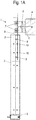
- a carrier 5 is provided on a ceiling 4 of a building, which is firmly fixed to the ceiling 4 via fastening bolts 6.
- the carrier 5 is angular or T-shaped and comprises a sword protruding from the ceiling 4 on which an insert 8 in the form of a steel profile is fixed.
- a post 2 can also be fixed to the carrier 5.
- an insert 8 is partially inserted into the post 2, the insert 8 being designed as a steel profile and being connected to the carrier 5 via fastening bolts 7.
- the insert 8 is connected to the post 2 via fastening means 9, for example fastening bolts.
- fastening means 10 are shown schematically on the insert 8, which connect a fire protection plate shown to the insert 8, wherein the fastening means 10 fix both the post 2 and the fire protection plate to the insert 8.
- the post 2 has, on the side facing away from the ceiling 4, two grooves 21 for inserting sealing profiles and a central screw groove 22 for fixing a pressure strip.
- the supporting structure 1 is shown in the area of the ceiling 4 in different sectional views.
- two fastening bolts 7 are shown, which pass through openings 70 in the form of elongated holes on the insert 8.
- the elongated holes extend parallel to the longitudinal direction of the insert 8 and thus enable a certain movement of the insert 8 in order to compensate for thermal stresses, but nevertheless ensure a secure fixation of the insert 8 on the carrier 5.
- the insert 8 is in a hollow chamber of the post 2 inserted and is connected there via fastening means to a fire protection plate which comprises an inner part 11 and an outer part 12.
- the outer part 12 that is to say the outer fire protection plate, is plate-shaped and can, for example, comprise sheet metal or glass and forms the outer visible surface of a facade.
- a part 11 of the fire protection plate is arranged on the inside, for example in the form of a steel cassette, which forms the inner closure of the fire protection plate.
- the outer part 12 is held on the insert 8 via an angle 15.
- the angle 15 is connected to the outer part 12, and a clasp holder is formed on the inwardly protruding web 13, that is to say a web which rests on a support bolt 14.
- the support bolt 14 is fixed on the insert 8.
- the outer part 12 of the fire protection panel is held on the posts 2 and bars 3, with cover and pressure strips 16 being provided on the outside which press the plate-shaped outer part 12 against seals on the posts 2 and bars 3. Should the mechanical If fixation via the cover and pressure strips 16 fails in the event of a fire, the outer part 12 can still not fall down and reveal the building opening, since it is fixed to the carrier via the fastening means with the clasp holder with the web 13, the support bolt 14 and the insert 8 5 is ensured, which is arranged on the ceiling 4.
- the fastening means and the carrier 5 are preferably made of steel which only melts at more than 1,500 ° C.
- the profiles of the post 2 and the bolt 3 can be made of a different material, for example aluminum.
- the inner part 11 of the fire protection plate can be designed as a steel cassette, for example filled with insulating material.
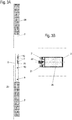
- each post 2 is shown which are connected to one another via the insert 8.
- the insert 8 protrudes over the lower post 2 and can therefore be inserted into a hollow chamber of the upper post 2 so that the two posts 2 are aligned in the assembled position.
- Shaped bodies made of cooling fire protection material 20 are inserted into each post 2, in particular a material that binds water in physical and / or chemical form, for example in the form of crystal water, so that it can cool and evaporate in the event of a fire.
- the fire protection material 20 is inserted into the post 2 in the area adjacent to the insert 8 in the longitudinal direction.
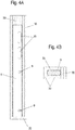
- the insert 8 is shown, which connects two posts 2, not shown, to one another.
- Shaped bodies 30 made of fire protection material can also be provided around the insert 8 in order to also cool the area around the insert 8 in the event of a fire.
- various fastening means are shown in order to fix a fire protection plate to the carrier 5 via the insert elements 8.
- the type of fastening means can be freely selected by the person skilled in the art, and the fastening means shown do not have to be used.
- Fastening bolts, hooks, angles, screws and other fastening elements can be used as fastening means, which are preferably made of steel and thus ensure that the fire protection panels are securely fixed for a long time in the event of fire.
Landscapes
- Engineering & Computer Science (AREA)
- Architecture (AREA)
- Physics & Mathematics (AREA)
- Electromagnetism (AREA)
- Civil Engineering (AREA)
- Structural Engineering (AREA)
- Building Environments (AREA)
- Special Wing (AREA)
- Load-Bearing And Curtain Walls (AREA)
Abstract
Description
- Die vorliegende Erfindung betrifft eine Tragkonstruktion in Brandschutzausführung bei Fenster, Türen und Fassaden, insbesondere Pfosten-Riegel-Konstruktionen wie auch Elementfassadenkonstruktionen, mit mindestens einem Pfosten, an dem mindestens ein Riegel fixiert ist, einem Einschiebling und einer Brandschutzplatte, wobei der mindestens eine Pfosten über einen Träger an einer Decke eines Gebäudes gehalten ist und der Einschiebling in einer Hohlkammer des Pfostens eingefügt ist.
- Die
DE 10 2016 006 683 offenbart ein Tragwerksystem als Pfosten-Riegel-Konstruktion, bei der Kühlmaterial in den Pfosten oder Riegeln angeordnet wird, um im Brandfall die Profile zu kühlen und somit die Standzeit zu erhöhen. Dieses Kühlmaterial kann über einen bestimmten Zeitraum Wasser abgeben und die Standzeit geringfügig erhöhen, allerdings kann nach dem Verdampfen des Wassers die Tragstruktur aus Pfosten und Riegeln, die meist aus Aluminium hergestellt ist, abschmelzen. Dies führt dazu, dass die Verkleidung sich von der Tragstruktur löst und herabfallen kann. Der Brand kann somit schneller in dem Gebäude durchdringen und zu hohen Schäden führen. - Die Einfügung von Brandschutzelementen ist zudem auch aus der
DE 100 03 953 A1 bekannt. - Es ist daher Aufgabe der vorliegenden Erfindung, eine Tragkonstruktion in Brandschutzausführung zu schaffen, die im Brandfall eine längere Fixierung von Brandschutzplatten gewährleistet.
- Diese Aufgabe wird mit einer Tragkonstruktion mit den Merkmalen des Anspruches 1 gelöst.
- Erfindungsgemäß ist an einem Pfosten der Tragkonstruktion ein Einschiebling in eine Hohlkammer eingefügt, wobei eine Brandschutzplatte über Befestigungsmittel an dem Einschiebling fixiert ist, die eine Öffnung in der Wand des Pfostens durchgreift. Dadurch kann eine mechanische Lastabtragung im Brandfall über den Einschiebling erfolgen, der aus einem anderen Material hergestellt ist als der Pfosten. Wenn der Pfosten im Brandfall weich wird und schmilzt, kann über den Einschiebling eine sichere Fixierung der Brandschutzplatte gewährleistet werden.
- Als Branschutzmaterialien für die Brandschutzplatte können Materialien eingesetzt werden, die nach der DIN 4102 / DIN EN 13501 in der aktuellen Fassung als nicht brennbar mit A1 oder A2 einklassifiziert sind.
- Vorzugsweise ist der Einschiebling an dem Träger gehalten, der an einer Decke eines Gebäudes fixiert ist. Der Träger kann beispielsweise als Stahlkonsole ausgebildet sein, der sowohl den Pfosten als auch den Einschiebling hält. Der Einschiebling kann mindestens eine Öffnung aufweisen, beispielsweise ein Langloch, das sich parallel zur Längsrichtung des Einschieblings erstreckt, die von mindestens einem Befestigungsbolzen durchgriffen ist, der an dem Träger fixiert ist. Dadurch kann eine sichere Fixierung des Einschieblings an dem Träger gewährleistet werden, wobei über eine Bewegbarkeit in Längsrichtung des Einschieblings Wärmespannungen ausgeglichen werden können.
- In einer bevorzugten Ausgestaltung fixieren die Befestigungsmittel die Brandschutzplatte gleichzeitig an dem Pfosten und dem Einschiebling. Dadurch kann die Anzahl der Befestigungsmittel reduziert werden.
- Die Befestigungsmittel können ferner eine Seitenwand des Pfostens durchgreifen und die Brandschutzplatte zwischen zwei Pfosten anordnen. Als Befestigungsmittel können Befestigungsbolzen, Schrauben, Haken und/oder eine Agraffenhalterung vorgesehen sein. Die Befestigungsmittel können dabei aus Stahl hergestellt sein, um auch im Brandfall eine sichere Fixierung der Brandschutzplatte zu gewährleisten.
- In einer bevorzugten Ausgestaltung ist der Einschiebling so angeordnet, dass er über einen Pfosten in Längsrichtung hervorsteht und der hervorstehende Teil des Einschieblings in einen zweiten Pfosten eingeschoben ist. Dadurch können zwei Pfosten fluchtend angeordnet werden und über den Einschiebling fixiert sein.
- Der Einschiebling ist vorzugsweise als Stahlprofil gebildet, wahlweise als Vollprofil oder Hohlprofil. Dabei muss der Einschiebling nicht eine Hohlkammer des Pfostens vollständig ausfüllen, sondern kann auch nur einen Teil der Hohlkammer belegen. Ein weiterer Teil der Hohlkammer kann wahlweise leer bleiben oder mit Brandschutzmaterial gefüllt sein, insbesondere Kühlmaterial, bei dem Wasser gebunden ist, das im Brandfall verdampft. Ein solches Kühlmaterial, beispielsweise Gipsplatten, kann sowohl in dem Pfosten als auch an der Außenseite angebracht sein.
- Die Erfindung wird nachfolgend anhand eines Ausführungsbeispiels mit Bezug auf die beigefügten Zeichnungen näher erläutert. Es zeigen:
- Figuren 1A und 1B
- zwei Ansichten einer erfindungsgemäßen Tragkonstruktion bei der Montage;
- Figuren 2A und 2C
- drei Ansichten der Tragkonstruktion der
Figur 1 nach der Montage und teilweise im Schnitt; - Figuren 3A und 3B
- zwei Ansichten von zwei Pfosten der Tragkonstruktion bei der Montage, und
- Figuren 4A und 4B
- zwei Ansichten eines Einschieblings mit Brandschutzmaterial.
- Eine Tragkonstruktion 1 umfasst eine Vielzahl von vertikalen Pfosten 2, an denen einer oder mehrere Riegel 3 fixiert sind, wobei die Pfosten 2 und Riegel 3 als Pfosten-Riegel-Konstruktion ausgebildet sein können, aber auch zu einem Rahmen einer Elementfassade zusammengesetzt werden können. Die Tragkonstruktion 1 kann auch für Fenster, Türen und Fassaden eingesetzt werden.
- Die Pfosten 2 und Riegel 3 bestehen vorzugsweise aus Leichtmetall, insbesondere Aluminium, und werden an einer Gebäudeöffnung fixiert. Hierfür ist an einer Decke 4 eines Gebäudes ein Träger 5 vorgesehen, der über Befestigungsbolzen 6 fest an der Decke 4 fixiert ist. Der Träger 5 ist dabei winkelförmig oder T-förmig ausgebildet und umfasst ein von der Decke 4 hervorstehendes Schwert, an dem ein Einschiebling 8 in Form eines Stahlprofils fixiert ist. Ferner kann an dem Träger 5 auch ein Pfosten 2 fixiert sein.
- In
Figur 1A ist in den Pfosten 2 ein Einschiebling 8 teilweise eingefügt, wobei der Einschiebling 8 als Stahlprofil ausgebildet ist und über Befestigungsbolzen 7 mit dem Träger 5 verbunden ist. Der Einschiebling 8 ist über Befestigungsmittel 9, beispielsweise Befestigungsbolzen, mit dem Pfosten 2 verbunden. Ferner sind an dem Einschiebling 8 schematisch dargestellte Befestigungsmittel 10 gezeigt, die eine dargestellte Brandschutzplatte mit dem Einschiebling 8 verbinden, wobei die Befestigungsmittel 10 sowohl den Pfosten 2 als auch die Brandschutzplatte an dem Einschiebling 8 fixieren. - Wie aus
Figur 1B ersichtlich ist, besitzt der Pfosten 2 auf der von der Decke 4 abgewandten Seite zwei Nuten 21 zum Einfügen von Dichtungsprofilen sowie eine mittige Schraubnut 22 zur Fixierung einer Andruckleiste. - In den
Figuren 2A bis 2C ist die Tragkonstruktion 1 im Bereich der Decke 4 in verschiedenen Schnittansichten gezeigt. An dem Schwert des Trägers 5 sind zwei Befestigungsbolzen 7 gezeigt, die Öffnungen 70 in Form von Langlöchern an dem Einschiebling 8 durchgreifen. Die Langlöcher erstrecken sich dabei parallel zur Längsrichtung des Einschieblings 8 und ermöglichen somit eine gewisse Bewegung des Einschieblings 8, um Wärmespannungen auszugleichen, aber sorgen dennoch für eine sichere Fixierung des Einschieblings 8 an dem Träger 5. Der Einschiebling 8 ist in eine Hohlkammer des Pfostens 2 eingeschoben und ist dort über Befestigungsmittel mit einer Brandschutzplatte verbunden, die einen inneren Teil 11 und einen äußeren Teil 12 umfasst. Der äußere Teil 12, also die äußere Brandschutzplatte, ist plattenförmig ausgebildet und kann beispielsweise Blech oder Glas umfassen und bildet die äußere sichtbare Oberfläche einer Fassade. Auf der Innenseite ist ein Teil 11 der Brandschutzplatte angeordnet, beispielsweise in Form einer Stahlkassette, die den inneren Abschluss der Brandschutzplatte bildet. - Der äußere Teil 12 ist über einen Winkel 15 an dem Einschiebling 8 gehalten. Hierfür ist der Winkel 15 mit dem äußeren Teil 12 verbunden, und an dem nach innen ragenden Steg 13 ist eine Agraffenhalterung ausgebildet, also ein Steg, der auf einem Tragbolzen 14 aufliegt. Der Tragbolzen 14 ist an dem Einschiebling 8 fixiert. Dadurch kann im Brandfall, wenn der Pfosten 2 und der Riegel 3 weich werden oder schmelzen, eine Fixierung des äußeren Teils 12 der Brandschutzplatte über den Winkel 15 erfolgen, der auf dem Tragbolzen 14 abgestützt ist, und der Tragbolzen 14 kann die Gewichtskräfte über den Einschiebling 8 auf den Träger 5 einleiten. Dadurch wird ein Herabfallen des äußeren Teils 12 und somit auch des inneren Teils 11 der Brandschutzplatte verhindert.
- Der äußere Teil 12 der Brandschutzplatte ist in der dargestellten Einbausituation an den Pfosten 2 und Riegeln 3 gehalten, wobei an der Außenseite Abdeck- und Andruckleisten 16 vorgesehen sind, die den plattenförmigen äußeren Teil 12 gegen Dichtungen an den Pfosten 2 und Riegeln 3 drücken. Sollte die mechanische Fixierung über die Abdeck- und Andruckleisten 16 im Brandfall versagen, so kann der äußere Teil 12 dennoch nicht herabfallen und die Gebäudeöffnung freigeben, da über die Befestigungsmittel mit der Agraffenhalterung mit dem Steg 13, dem Tragbolzen 14 und dem Einschiebling 8 eine Fixierung an dem Träger 5 gewährleistet wird, der an der Decke 4 angeordnet ist. Die Befestigungsmittel und der Träger 5 sind vorzugsweise aus Stahl hergestellt, der erst bei mehr als 1.500 °C schmilzt. Die Profile des Pfostens 2 und der Riegel 3 können aus einem anderen Material, beispielsweise aus Aluminium, dargestellt sein.
- Der innere Teil 11 der Brandschutzplatte kann als Stahlkassette ausgebildet sein, beispielsweise gefüllt mit Isoliermaterial.
- In den
Figuren 3A und 3B sind zwei Pfosten 2 gezeigt, die über den Einschiebling 8 miteinander verbunden werden. Der Einschiebling 8 steht über den unteren Pfosten 2 hervor und kann daher in eine Hohlkammer des oberen Pfostens 2 eingefügt werden, so dass die beiden Pfosten 2 in der montierten Position fluchtend angeordnet sind. In jedem Pfosten 2 sind Formkörper aus kühlendem Brandschutzmaterial 20 eingefügt, insbesondere ein Material, das Wasser in physikalischer und/oder chemischer Form bindet, beispielsweise in Form von Kristallwasser, damit dieses dann im Brandfall kühlen und verdampfen kann. Das Brandschutzmaterial 20 ist in dem Bereich benachbart zu dem Einschiebling 8 in Längsrichtung in den Pfosten 2 eingefügt. - In den
Figuren 4A und 4B ist der Einschiebling 8 gezeigt, der zwei nicht gezeigte Pfosten 2 miteinander verbindet. Auch um den Einschiebling 8 können Formkörper 30 aus Brandschutzmaterial vorgesehen werden, um auch den Bereich um den Einschiebling 8 im Brandfall zu kühlen. - In dem dargestellten Ausführungsbeispiel sind diverse Befestigungsmittel gezeigt, um eine Brandschutzplatte über die Einschieblinge 8 an dem Träger 5 zu fixieren. Die Art der Befestigungsmittel kann vom Fachmann frei gewählt werden, und es müssen nicht die dargestellten Befestigungsmittel eingesetzt werden. Als Befestigungsmittel können Befestigungsbolzen, Haken, Winkel, Schrauben und andere Befestigungselemente eingesetzt werden, die vorzugsweise aus Stahl hergestellt sind und somit im Brandfall lange Zeit eine sichere Fixierung der Brandschutzplatten gewährleisten.
-
- 1
- Tragkonstruktion
- 2
- Pfosten
- 3
- Riegel
- 4
- Decke
- 5
- Träger
- 6
- Befestigungsbolzen
- 7
- Befestigungsbolzen
- 8
- Einschiebling
- 9
- Befestigungsmittel
- 10
- Befestigungsmittel
- 11
- innerer Teil
- 12
- äußerer Teil
- 13
- Steg
- 14
- Tragbolzen
- 15
- Winkel
- 16
- Abdeck- und Andruckleiste
- 20
- Brandschutzmaterial
- 21
- Nut
- 22
- Schraubnut
- 30
- Formkörper
- 70
- Öffnung
Claims (11)
- Tragkonstruktion (1) in Brandschutzausführung, insbesondere Pfosten-Riegel-Konstruktion, mit mindestens einem Pfosten (2), an dem mindestens ein Riegel (3) fixiert ist, einem Einschiebling (8) und einer Brandschutzplatte (11, 12), wobei der mindestens eine Pfosten (2) über einen Träger (5) an einer Decke (4) eines Gebäudes gehalten ist und der Einschiebling (8) in einer Hohlkammer des Pfostens (2) eingefügt ist, dadurch gekennzeichnet, dass die Brandschutzplatte (11, 12) über Befestigungsmittel (10, 13, 14, 15) an dem Einschiebling (8) fixiert ist, die eine Öffnung in der Wand des Pfostens (2) durchgreifen.
- Tragkonstruktion nach Anspruch 1, dadurch gekennzeichnet, dass der Einschiebling (8) an dem Träger (5) gehalten ist.
- Tragkonstruktion nach Anspruch 2, dadurch gekennzeichnet, dass in dem Einschiebling (8) mindestens eine Öffnung (70) ausgebildet ist, die von einem an dem Träger (5) fixierten Befestigungsbolzen (7) durchgriffen ist.
- Tragkonstruktion nach einem der vorhergehenden Ansprüche, dadurch gekennzeichnet, dass die Befestigungsmittel (10, 13, 14, 15) die Brandschutzplatte (11, 12) gleichzeitig an dem Pfosten (2) und dem Einschiebling (8) fixieren.
- Tragkonstruktion nach einem der vorhergehenden Ansprüche, dadurch gekennzeichnet, dass die Befestigungsmittel (14) eine Seitenwand des Pfostens (2) durchgreifen und die Brandschutzplatte (11, 12) zwischen zwei Pfosten (2) und/oder vor der durch die zwei Pfosten (2) gebildeten Ebene angeordnet ist.
- Tragkonstruktion nach einem der vorhergehenden Ansprüche, dadurch gekennzeichnet, dass der Einschiebling (8) zwei fluchtend angeordnete Pfosten (2) miteinander verbindet.
- Tragkonstruktion nach einem der vorhergehenden Ansprüche, dadurch gekennzeichnet, dass der Einschiebling (8) als Stahlprofil ausgebildet ist.
- Tragkonstruktion nach einem der vorhergehenden Ansprüche, dadurch gekennzeichnet, dass der Träger (5) und die Befestigungsmittel (10, 13, 14, 15) aus Stahl hergestellt sind.
- Tragkonstruktion nach einem der vorhergehenden Ansprüche, dadurch gekennzeichnet, dass die Befestigungsmittel (10, 13, 14, 15) eine Agraffenhalterung umfassen.
- Tragkonstruktion nach einem der vorhergehenden Ansprüche, dadurch gekennzeichnet, dass der mindestens eine Pfosten (2) mit Brandschutzmaterial (20, 30) gefüllt und/oder ummantelt ist.
- Tragkonstruktion nach einem der vorhergehenden Ansprüche, dadurch gekennzeichnet, dass die Brandschutzplatte (11, 12) eine Stahlkassette umfasst, die zwischen zwei Pfosten (2) fixiert ist.
Priority Applications (1)
| Application Number | Priority Date | Filing Date | Title |
|---|---|---|---|
| HRP20240430TT HRP20240430T1 (hr) | 2019-11-29 | 2020-11-06 | Nosiva konstrukcija, u vatrootpornoj izvedbi |
Applications Claiming Priority (1)
| Application Number | Priority Date | Filing Date | Title |
|---|---|---|---|
| DE102019132519.6A DE102019132519A1 (de) | 2019-11-29 | 2019-11-29 | Tragkonstruktion in Brandschutzausführung |
Publications (2)
| Publication Number | Publication Date |
|---|---|
| EP3828356A1 true EP3828356A1 (de) | 2021-06-02 |
| EP3828356B1 EP3828356B1 (de) | 2024-01-10 |
Family
ID=73172487
Family Applications (1)
| Application Number | Title | Priority Date | Filing Date |
|---|---|---|---|
| EP20206102.4A Active EP3828356B1 (de) | 2019-11-29 | 2020-11-06 | Tragkonstruktion in brandschutzausführung |
Country Status (8)
| Country | Link |
|---|---|
| EP (1) | EP3828356B1 (de) |
| DE (1) | DE102019132519A1 (de) |
| DK (1) | DK3828356T3 (de) |
| ES (1) | ES2973645T3 (de) |
| FI (1) | FI3828356T3 (de) |
| HR (1) | HRP20240430T1 (de) |
| HU (1) | HUE066224T2 (de) |
| PL (1) | PL3828356T3 (de) |
Citations (6)
| Publication number | Priority date | Publication date | Assignee | Title |
|---|---|---|---|---|
| FR2754283A1 (fr) * | 1996-10-04 | 1998-04-10 | Verrieres Zenith | Element de paroi vitree |
| DE10003953A1 (de) | 2000-01-29 | 2001-08-09 | Wicona Bausysteme Gmbh | Fassade oder Glasdach in Brandschutzausführung mit einer aus vertikalen und horizontalen Profilen bestehenden Tragkonstruktion |
| JP2001311251A (ja) * | 2000-04-27 | 2001-11-09 | Shin Nikkei Co Ltd | カーテンウォール構造 |
| US20030033764A1 (en) * | 2001-08-20 | 2003-02-20 | Ting Raymond M.L. | Mullion splice joint design |
| DE102016006683A1 (de) | 2016-05-31 | 2017-11-30 | Lamilux Heinrich Strunz Gmbh | Brandschutzdach |
| CN206971500U (zh) * | 2017-07-05 | 2018-02-06 | 广州艾力克装饰工程有限公司 | 单元式防火隔热玻璃幕墙 |
-
2019
- 2019-11-29 DE DE102019132519.6A patent/DE102019132519A1/de active Pending
-
2020
- 2020-11-06 EP EP20206102.4A patent/EP3828356B1/de active Active
- 2020-11-06 HR HRP20240430TT patent/HRP20240430T1/hr unknown
- 2020-11-06 FI FIEP20206102.4T patent/FI3828356T3/fi not_active Application Discontinuation
- 2020-11-06 HU HUE20206102A patent/HUE066224T2/hu unknown
- 2020-11-06 DK DK20206102.4T patent/DK3828356T3/da active
- 2020-11-06 PL PL20206102.4T patent/PL3828356T3/pl unknown
- 2020-11-06 ES ES20206102T patent/ES2973645T3/es active Active
Patent Citations (6)
| Publication number | Priority date | Publication date | Assignee | Title |
|---|---|---|---|---|
| FR2754283A1 (fr) * | 1996-10-04 | 1998-04-10 | Verrieres Zenith | Element de paroi vitree |
| DE10003953A1 (de) | 2000-01-29 | 2001-08-09 | Wicona Bausysteme Gmbh | Fassade oder Glasdach in Brandschutzausführung mit einer aus vertikalen und horizontalen Profilen bestehenden Tragkonstruktion |
| JP2001311251A (ja) * | 2000-04-27 | 2001-11-09 | Shin Nikkei Co Ltd | カーテンウォール構造 |
| US20030033764A1 (en) * | 2001-08-20 | 2003-02-20 | Ting Raymond M.L. | Mullion splice joint design |
| DE102016006683A1 (de) | 2016-05-31 | 2017-11-30 | Lamilux Heinrich Strunz Gmbh | Brandschutzdach |
| CN206971500U (zh) * | 2017-07-05 | 2018-02-06 | 广州艾力克装饰工程有限公司 | 单元式防火隔热玻璃幕墙 |
Also Published As
| Publication number | Publication date |
|---|---|
| HUE066224T2 (hu) | 2024-07-28 |
| FI3828356T3 (fi) | 2024-03-28 |
| DE102019132519A1 (de) | 2021-06-02 |
| EP3828356B1 (de) | 2024-01-10 |
| ES2973645T3 (es) | 2024-06-21 |
| PL3828356T3 (pl) | 2024-05-20 |
| DK3828356T3 (da) | 2024-03-11 |
| HRP20240430T1 (hr) | 2024-06-21 |
Similar Documents
| Publication | Publication Date | Title |
|---|---|---|
| EP0933486B2 (de) | Fassade oder Glasdach in Brandschutzausführung | |
| EP0086976A1 (de) | Brandschutzelement | |
| DE102009023883B4 (de) | Fassadenelement | |
| EP3060725B1 (de) | Durchbruchhemmender verbund sowie ständerwand-, dach- oder deckenkonstruktion | |
| EP3828356B1 (de) | Tragkonstruktion in brandschutzausführung | |
| EP0100431A1 (de) | Schall- und wärmedämmende Wandverkleidung | |
| DE19704112C2 (de) | Wärmedämmende Fassadenverkleidung | |
| DE60223885T2 (de) | Feuerbeständige Rahmen/Paneel Struktur | |
| EP0415201B1 (de) | Vorrichtung zur Befestigung von plattenförmigen Fassadenelementen | |
| EP1944429B1 (de) | Revisionsabdeckung | |
| EP4353938A1 (de) | Plattenförmiges tragesystem zur leibungsauskragenden montage von bauelementen | |
| DE102020101582A1 (de) | Türflügel sowie tür mit einem blendrahmen und einem türflügel | |
| DE102010032947B4 (de) | Aufsatzkonstruktion für Pfosten-Riegelelemente mit verbesserter Wärmeisoliereigenschaft | |
| DE19805913A1 (de) | Fassadenelement zur Bekleidung von Außenwänden und deren Halterung sowie eine Fassadenbekleidung | |
| DE102006052648A1 (de) | Traganker zur Befestigung von Fassadenelementen an einer Gebäudewand | |
| EP2836662B1 (de) | Dichtsystem zwischen einem fensterrahmen und einer wand eines gebäudes | |
| EP3315679A1 (de) | Verbindungssystem | |
| DE202020000211U1 (de) | Distanzstück und System zum dauerhaften Befestigen eines Bauteils an wenigstens einem Befestigungspunkt | |
| DE102016102780B4 (de) | Anordnung mit mindestens einem Dach- oder Fassadenelement in Gestalt eines sandwichartig aufgebauten Dämmpaneels und mit einem benachbart zu dem Dach- oder Fassadenelement angeordneten Fensterelement | |
| EP2295698B1 (de) | Profilanordnung, insbesondere für ein Fenster oder eine Tür sowie Fenster oder Tür | |
| DE102008040296B4 (de) | Pfosten für eine Pfosten-Riegel- oder Elementkonstruktion, Verfahren zu dessen Herstellung und Pfosten-Riegel- oder Elementkonstruktion, die einen Pfosten aufweist | |
| DE3448392C2 (de) | Keramische Fassadenplatte | |
| EP1582643A2 (de) | Pfosten-Riegel-System mit geringer Ansichtsbreite | |
| EP1319790A2 (de) | Fenster- und Türanker | |
| DE102007053659A1 (de) | Gebäudefassade in Brandschutzausführung |
Legal Events
| Date | Code | Title | Description |
|---|---|---|---|
| PUAI | Public reference made under article 153(3) epc to a published international application that has entered the european phase |
Free format text: ORIGINAL CODE: 0009012 |
|
| STAA | Information on the status of an ep patent application or granted ep patent |
Free format text: STATUS: THE APPLICATION HAS BEEN PUBLISHED |
|
| AK | Designated contracting states |
Kind code of ref document: A1 Designated state(s): AL AT BE BG CH CY CZ DE DK EE ES FI FR GB GR HR HU IE IS IT LI LT LU LV MC MK MT NL NO PL PT RO RS SE SI SK SM TR |
|
| STAA | Information on the status of an ep patent application or granted ep patent |
Free format text: STATUS: REQUEST FOR EXAMINATION WAS MADE |
|
| 17P | Request for examination filed |
Effective date: 20211104 |
|
| RBV | Designated contracting states (corrected) |
Designated state(s): AL AT BE BG CH CY CZ DE DK EE ES FI FR GB GR HR HU IE IS IT LI LT LU LV MC MK MT NL NO PL PT RO RS SE SI SK SM TR |
|
| GRAP | Despatch of communication of intention to grant a patent |
Free format text: ORIGINAL CODE: EPIDOSNIGR1 |
|
| STAA | Information on the status of an ep patent application or granted ep patent |
Free format text: STATUS: GRANT OF PATENT IS INTENDED |
|
| GRAS | Grant fee paid |
Free format text: ORIGINAL CODE: EPIDOSNIGR3 |
|
| GRAA | (expected) grant |
Free format text: ORIGINAL CODE: 0009210 |
|
| STAA | Information on the status of an ep patent application or granted ep patent |
Free format text: STATUS: THE PATENT HAS BEEN GRANTED |
|
| RIC1 | Information provided on ipc code assigned before grant |
Ipc: E04B 1/94 20060101ALN20231108BHEP Ipc: E04B 2/96 20060101AFI20231108BHEP |
|
| INTG | Intention to grant announced |
Effective date: 20231121 |
|
| P01 | Opt-out of the competence of the unified patent court (upc) registered |
Effective date: 20231124 |
|
| AK | Designated contracting states |
Kind code of ref document: B1 Designated state(s): AL AT BE BG CH CY CZ DE DK EE ES FI FR GB GR HR HU IE IS IT LI LT LU LV MC MK MT NL NO PL PT RO RS SE SI SK SM TR |
|
| REG | Reference to a national code |
Ref country code: GB Ref legal event code: FG4D Free format text: NOT ENGLISH |
|
| REG | Reference to a national code |
Ref country code: CH Ref legal event code: EP |
|
| REG | Reference to a national code |
Ref country code: DE Ref legal event code: R096 Ref document number: 502020006673 Country of ref document: DE |
|
| REG | Reference to a national code |
Ref country code: IE Ref legal event code: FG4D Free format text: LANGUAGE OF EP DOCUMENT: GERMAN |
|
| REG | Reference to a national code |
Ref country code: NL Ref legal event code: FP |
|
| REG | Reference to a national code |
Ref country code: DK Ref legal event code: T3 Effective date: 20240308 |
|
| REG | Reference to a national code |
Ref country code: FI Ref legal event code: FGE |
|
| REG | Reference to a national code |
Ref country code: SE Ref legal event code: TRGR |
|
| REG | Reference to a national code |
Ref country code: LT Ref legal event code: MG9D |
|
| REG | Reference to a national code |
Ref country code: EE Ref legal event code: FG4A Ref document number: E024208 Country of ref document: EE Effective date: 20240322 |
|
| REG | Reference to a national code |
Ref country code: HR Ref legal event code: T1PR Ref document number: P20240430 Country of ref document: HR Ref country code: ES Ref legal event code: FG2A Ref document number: 2973645 Country of ref document: ES Kind code of ref document: T3 Effective date: 20240621 |
|
| PG25 | Lapsed in a contracting state [announced via postgrant information from national office to epo] |
Ref country code: IS Free format text: LAPSE BECAUSE OF FAILURE TO SUBMIT A TRANSLATION OF THE DESCRIPTION OR TO PAY THE FEE WITHIN THE PRESCRIBED TIME-LIMIT Effective date: 20240510 |
|
| PG25 | Lapsed in a contracting state [announced via postgrant information from national office to epo] |
Ref country code: LT Free format text: LAPSE BECAUSE OF FAILURE TO SUBMIT A TRANSLATION OF THE DESCRIPTION OR TO PAY THE FEE WITHIN THE PRESCRIBED TIME-LIMIT Effective date: 20240110 |
|
| PG25 | Lapsed in a contracting state [announced via postgrant information from national office to epo] |
Ref country code: GR Free format text: LAPSE BECAUSE OF FAILURE TO SUBMIT A TRANSLATION OF THE DESCRIPTION OR TO PAY THE FEE WITHIN THE PRESCRIBED TIME-LIMIT Effective date: 20240411 |
|
| PG25 | Lapsed in a contracting state [announced via postgrant information from national office to epo] |
Ref country code: RS Free format text: LAPSE BECAUSE OF FAILURE TO SUBMIT A TRANSLATION OF THE DESCRIPTION OR TO PAY THE FEE WITHIN THE PRESCRIBED TIME-LIMIT Effective date: 20240410 |
|
| REG | Reference to a national code |
Ref country code: HU Ref legal event code: AG4A Ref document number: E066224 Country of ref document: HU |
|
| PG25 | Lapsed in a contracting state [announced via postgrant information from national office to epo] |
Ref country code: RS Free format text: LAPSE BECAUSE OF FAILURE TO SUBMIT A TRANSLATION OF THE DESCRIPTION OR TO PAY THE FEE WITHIN THE PRESCRIBED TIME-LIMIT Effective date: 20240410 Ref country code: LT Free format text: LAPSE BECAUSE OF FAILURE TO SUBMIT A TRANSLATION OF THE DESCRIPTION OR TO PAY THE FEE WITHIN THE PRESCRIBED TIME-LIMIT Effective date: 20240110 Ref country code: IS Free format text: LAPSE BECAUSE OF FAILURE TO SUBMIT A TRANSLATION OF THE DESCRIPTION OR TO PAY THE FEE WITHIN THE PRESCRIBED TIME-LIMIT Effective date: 20240510 Ref country code: GR Free format text: LAPSE BECAUSE OF FAILURE TO SUBMIT A TRANSLATION OF THE DESCRIPTION OR TO PAY THE FEE WITHIN THE PRESCRIBED TIME-LIMIT Effective date: 20240411 Ref country code: BG Free format text: LAPSE BECAUSE OF FAILURE TO SUBMIT A TRANSLATION OF THE DESCRIPTION OR TO PAY THE FEE WITHIN THE PRESCRIBED TIME-LIMIT Effective date: 20240110 |
|
| PG25 | Lapsed in a contracting state [announced via postgrant information from national office to epo] |
Ref country code: PT Free format text: LAPSE BECAUSE OF FAILURE TO SUBMIT A TRANSLATION OF THE DESCRIPTION OR TO PAY THE FEE WITHIN THE PRESCRIBED TIME-LIMIT Effective date: 20240510 |
|
| PG25 | Lapsed in a contracting state [announced via postgrant information from national office to epo] |
Ref country code: PT Free format text: LAPSE BECAUSE OF FAILURE TO SUBMIT A TRANSLATION OF THE DESCRIPTION OR TO PAY THE FEE WITHIN THE PRESCRIBED TIME-LIMIT Effective date: 20240510 |
|
| REG | Reference to a national code |
Ref country code: DE Ref legal event code: R097 Ref document number: 502020006673 Country of ref document: DE |
|
| PG25 | Lapsed in a contracting state [announced via postgrant information from national office to epo] |
Ref country code: SM Free format text: LAPSE BECAUSE OF FAILURE TO SUBMIT A TRANSLATION OF THE DESCRIPTION OR TO PAY THE FEE WITHIN THE PRESCRIBED TIME-LIMIT Effective date: 20240110 |
|
| PG25 | Lapsed in a contracting state [announced via postgrant information from national office to epo] |
Ref country code: SK Free format text: LAPSE BECAUSE OF FAILURE TO SUBMIT A TRANSLATION OF THE DESCRIPTION OR TO PAY THE FEE WITHIN THE PRESCRIBED TIME-LIMIT Effective date: 20240110 |
|
| PG25 | Lapsed in a contracting state [announced via postgrant information from national office to epo] |
Ref country code: SM Free format text: LAPSE BECAUSE OF FAILURE TO SUBMIT A TRANSLATION OF THE DESCRIPTION OR TO PAY THE FEE WITHIN THE PRESCRIBED TIME-LIMIT Effective date: 20240110 Ref country code: SK Free format text: LAPSE BECAUSE OF FAILURE TO SUBMIT A TRANSLATION OF THE DESCRIPTION OR TO PAY THE FEE WITHIN THE PRESCRIBED TIME-LIMIT Effective date: 20240110 Ref country code: RO Free format text: LAPSE BECAUSE OF FAILURE TO SUBMIT A TRANSLATION OF THE DESCRIPTION OR TO PAY THE FEE WITHIN THE PRESCRIBED TIME-LIMIT Effective date: 20240110 |
|
| PLBE | No opposition filed within time limit |
Free format text: ORIGINAL CODE: 0009261 |
|
| STAA | Information on the status of an ep patent application or granted ep patent |
Free format text: STATUS: NO OPPOSITION FILED WITHIN TIME LIMIT |
|
| REG | Reference to a national code |
Ref country code: HR Ref legal event code: ODRP Ref document number: P20240430 Country of ref document: HR Payment date: 20241104 Year of fee payment: 5 |
|
| 26N | No opposition filed |
Effective date: 20241011 |
|
| PG25 | Lapsed in a contracting state [announced via postgrant information from national office to epo] |
Ref country code: SI Free format text: LAPSE BECAUSE OF FAILURE TO SUBMIT A TRANSLATION OF THE DESCRIPTION OR TO PAY THE FEE WITHIN THE PRESCRIBED TIME-LIMIT Effective date: 20240110 |
|
| PG25 | Lapsed in a contracting state [announced via postgrant information from national office to epo] |
Ref country code: MC Free format text: LAPSE BECAUSE OF FAILURE TO SUBMIT A TRANSLATION OF THE DESCRIPTION OR TO PAY THE FEE WITHIN THE PRESCRIBED TIME-LIMIT Effective date: 20240110 |
|
| REG | Reference to a national code |
Ref country code: HR Ref legal event code: ODRP Ref document number: P20240430 Country of ref document: HR Payment date: 20251029 Year of fee payment: 6 |
|
| REG | Reference to a national code |
Ref country code: CH Ref legal event code: U11 Free format text: ST27 STATUS EVENT CODE: U-0-0-U10-U11 (AS PROVIDED BY THE NATIONAL OFFICE) Effective date: 20251201 |
|
| PGFP | Annual fee paid to national office [announced via postgrant information from national office to epo] |
Ref country code: HU Payment date: 20251031 Year of fee payment: 6 |
|
| PGFP | Annual fee paid to national office [announced via postgrant information from national office to epo] |
Ref country code: NL Payment date: 20251104 Year of fee payment: 6 Ref country code: LU Payment date: 20251118 Year of fee payment: 6 |
|
| PGFP | Annual fee paid to national office [announced via postgrant information from national office to epo] |
Ref country code: DE Payment date: 20251020 Year of fee payment: 6 |
|
| PGFP | Annual fee paid to national office [announced via postgrant information from national office to epo] |
Ref country code: GB Payment date: 20251031 Year of fee payment: 6 |
|
| PGFP | Annual fee paid to national office [announced via postgrant information from national office to epo] |
Ref country code: NO Payment date: 20251020 Year of fee payment: 6 |
|
| PGFP | Annual fee paid to national office [announced via postgrant information from national office to epo] |
Ref country code: AT Payment date: 20251104 Year of fee payment: 6 |
|
| PGFP | Annual fee paid to national office [announced via postgrant information from national office to epo] |
Ref country code: IT Payment date: 20251128 Year of fee payment: 6 Ref country code: FI Payment date: 20251118 Year of fee payment: 6 Ref country code: DK Payment date: 20251031 Year of fee payment: 6 |
|
| PGFP | Annual fee paid to national office [announced via postgrant information from national office to epo] |
Ref country code: HR Payment date: 20251029 Year of fee payment: 6 Ref country code: FR Payment date: 20251031 Year of fee payment: 6 |
|
| PGFP | Annual fee paid to national office [announced via postgrant information from national office to epo] |
Ref country code: BE Payment date: 20251104 Year of fee payment: 6 Ref country code: TR Payment date: 20251103 Year of fee payment: 6 |
|
| PGFP | Annual fee paid to national office [announced via postgrant information from national office to epo] |
Ref country code: CH Payment date: 20251201 Year of fee payment: 6 Ref country code: SE Payment date: 20251104 Year of fee payment: 6 |
|
| PGFP | Annual fee paid to national office [announced via postgrant information from national office to epo] |
Ref country code: IE Payment date: 20251104 Year of fee payment: 6 Ref country code: CZ Payment date: 20251020 Year of fee payment: 6 |
|
| PGFP | Annual fee paid to national office [announced via postgrant information from national office to epo] |
Ref country code: LV Payment date: 20251125 Year of fee payment: 6 |
|
| PGFP | Annual fee paid to national office [announced via postgrant information from national office to epo] |
Ref country code: PL Payment date: 20251017 Year of fee payment: 6 |
|
| PGFP | Annual fee paid to national office [announced via postgrant information from national office to epo] |
Ref country code: EE Payment date: 20251120 Year of fee payment: 6 |
|
| PGFP | Annual fee paid to national office [announced via postgrant information from national office to epo] |
Ref country code: ES Payment date: 20251216 Year of fee payment: 6 |
|
| PG25 | Lapsed in a contracting state [announced via postgrant information from national office to epo] |
Ref country code: CY Free format text: LAPSE BECAUSE OF FAILURE TO SUBMIT A TRANSLATION OF THE DESCRIPTION OR TO PAY THE FEE WITHIN THE PRESCRIBED TIME-LIMIT; INVALID AB INITIO Effective date: 20201106 |