EP3822148B1 - Nutzfahrzeug - Google Patents
Nutzfahrzeug Download PDFInfo
- Publication number
- EP3822148B1 EP3822148B1 EP19835105.8A EP19835105A EP3822148B1 EP 3822148 B1 EP3822148 B1 EP 3822148B1 EP 19835105 A EP19835105 A EP 19835105A EP 3822148 B1 EP3822148 B1 EP 3822148B1
- Authority
- EP
- European Patent Office
- Prior art keywords
- steering
- working
- switch
- automatic steering
- vehicle body
- Prior art date
- Legal status (The legal status is an assumption and is not a legal conclusion. Google has not performed a legal analysis and makes no representation as to the accuracy of the status listed.)
- Active
Links
Images


Classifications
-
- A—HUMAN NECESSITIES
- A01—AGRICULTURE; FORESTRY; ANIMAL HUSBANDRY; HUNTING; TRAPPING; FISHING
- A01B—SOIL WORKING IN AGRICULTURE OR FORESTRY; PARTS, DETAILS, OR ACCESSORIES OF AGRICULTURAL MACHINES OR IMPLEMENTS, IN GENERAL
- A01B69/00—Steering of agricultural machines or implements; Guiding agricultural machines or implements on a desired track
- A01B69/007—Steering or guiding of agricultural vehicles, e.g. steering of the tractor to keep the plough in the furrow
- A01B69/008—Steering or guiding of agricultural vehicles, e.g. steering of the tractor to keep the plough in the furrow automatic
-
- A—HUMAN NECESSITIES
- A01—AGRICULTURE; FORESTRY; ANIMAL HUSBANDRY; HUNTING; TRAPPING; FISHING
- A01B—SOIL WORKING IN AGRICULTURE OR FORESTRY; PARTS, DETAILS, OR ACCESSORIES OF AGRICULTURAL MACHINES OR IMPLEMENTS, IN GENERAL
- A01B63/00—Lifting or adjusting devices or arrangements for agricultural machines or implements
- A01B63/02—Lifting or adjusting devices or arrangements for agricultural machines or implements for implements mounted on tractors
- A01B63/10—Lifting or adjusting devices or arrangements for agricultural machines or implements for implements mounted on tractors operated by hydraulic or pneumatic means
- A01B63/102—Lifting or adjusting devices or arrangements for agricultural machines or implements for implements mounted on tractors operated by hydraulic or pneumatic means characterised by the location of the mounting on the tractor, e.g. on the rear part
-
- A—HUMAN NECESSITIES
- A01—AGRICULTURE; FORESTRY; ANIMAL HUSBANDRY; HUNTING; TRAPPING; FISHING
- A01B—SOIL WORKING IN AGRICULTURE OR FORESTRY; PARTS, DETAILS, OR ACCESSORIES OF AGRICULTURAL MACHINES OR IMPLEMENTS, IN GENERAL
- A01B69/00—Steering of agricultural machines or implements; Guiding agricultural machines or implements on a desired track
- A01B69/003—Steering or guiding of machines or implements pushed or pulled by or mounted on agricultural vehicles such as tractors, e.g. by lateral shifting of the towing connection
- A01B69/004—Steering or guiding of machines or implements pushed or pulled by or mounted on agricultural vehicles such as tractors, e.g. by lateral shifting of the towing connection automatic
-
- B—PERFORMING OPERATIONS; TRANSPORTING
- B62—LAND VEHICLES FOR TRAVELLING OTHERWISE THAN ON RAILS
- B62D—MOTOR VEHICLES; TRAILERS
- B62D1/00—Steering controls, i.e. means for initiating a change of direction of the vehicle
- B62D1/02—Steering controls, i.e. means for initiating a change of direction of the vehicle vehicle-mounted
- B62D1/04—Hand wheels
- B62D1/046—Adaptations on rotatable parts of the steering wheel for accommodation of switches
-
- B—PERFORMING OPERATIONS; TRANSPORTING
- B62—LAND VEHICLES FOR TRAVELLING OTHERWISE THAN ON RAILS
- B62D—MOTOR VEHICLES; TRAILERS
- B62D15/00—Steering not otherwise provided for
- B62D15/02—Steering position indicators ; Steering position determination; Steering aids
- B62D15/025—Active steering aids, e.g. helping the driver by actively influencing the steering system after environment evaluation
-
- B—PERFORMING OPERATIONS; TRANSPORTING
- B62—LAND VEHICLES FOR TRAVELLING OTHERWISE THAN ON RAILS
- B62D—MOTOR VEHICLES; TRAILERS
- B62D5/00—Power-assisted or power-driven steering
- B62D5/06—Power-assisted or power-driven steering fluid, i.e. using a pressurised fluid for most or all the force required for steering a vehicle
- B62D5/07—Supply of pressurised fluid for steering also supplying other consumers ; control thereof
-
- B—PERFORMING OPERATIONS; TRANSPORTING
- B62—LAND VEHICLES FOR TRAVELLING OTHERWISE THAN ON RAILS
- B62D—MOTOR VEHICLES; TRAILERS
- B62D6/00—Arrangements for automatically controlling steering depending on driving conditions sensed and responded to, e.g. control circuits
-
- A—HUMAN NECESSITIES
- A01—AGRICULTURE; FORESTRY; ANIMAL HUSBANDRY; HUNTING; TRAPPING; FISHING
- A01B—SOIL WORKING IN AGRICULTURE OR FORESTRY; PARTS, DETAILS, OR ACCESSORIES OF AGRICULTURAL MACHINES OR IMPLEMENTS, IN GENERAL
- A01B59/00—Devices specially adapted for connection between animals or tractors and agricultural machines or implements
- A01B59/06—Devices specially adapted for connection between animals or tractors and agricultural machines or implements for machines mounted on tractors
- A01B59/066—Devices specially adapted for connection between animals or tractors and agricultural machines or implements for machines mounted on tractors of the type comprising at least two lower arms and one upper arm generally arranged in a triangle, e.g. three-point hitches
-
- A—HUMAN NECESSITIES
- A01—AGRICULTURE; FORESTRY; ANIMAL HUSBANDRY; HUNTING; TRAPPING; FISHING
- A01B—SOIL WORKING IN AGRICULTURE OR FORESTRY; PARTS, DETAILS, OR ACCESSORIES OF AGRICULTURAL MACHINES OR IMPLEMENTS, IN GENERAL
- A01B63/00—Lifting or adjusting devices or arrangements for agricultural machines or implements
- A01B63/02—Lifting or adjusting devices or arrangements for agricultural machines or implements for implements mounted on tractors
- A01B63/10—Lifting or adjusting devices or arrangements for agricultural machines or implements for implements mounted on tractors operated by hydraulic or pneumatic means
- A01B63/1006—Lifting or adjusting devices or arrangements for agricultural machines or implements for implements mounted on tractors operated by hydraulic or pneumatic means the hydraulic or pneumatic means structurally belonging to the tractor
-
- B—PERFORMING OPERATIONS; TRANSPORTING
- B60—VEHICLES IN GENERAL
- B60Y—INDEXING SCHEME RELATING TO ASPECTS CROSS-CUTTING VEHICLE TECHNOLOGY
- B60Y2200/00—Type of vehicle
- B60Y2200/20—Off-Road Vehicles
- B60Y2200/22—Agricultural vehicles
Definitions
- the automatic traveling can be easily performed by switching from the manual traveling to the automatic traveling with a changeover switch.
- the control of automatic traveling is not changed even when various types of working devices are attached to the agricultural machine, and the automatic traveling suitable for the types of the working devices.
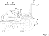
- the front side of an operator seated on an operator seat 10 of the tractor (working vehicle) 1 (a direction of an arrowed line A1 in FIG. 14 ) will be referred to as the front
- the rear side of the operator (a direction of an arrowed line A2 in FIG. 14 ) will be referred to as the rear
- the left side of the operator will be referred to as the left
- the right side of the operator will be referred to as the right.
- the horizontal direction which is a direction orthogonal to the front-to-back direction of the working vehicle 1, is referred to as a vehicle width direction.
- the tractor 1 is provided with a vehicle body 3, a prime mover 4, and a speed-shifter device 5.
- the vehicle body 3 has a traveling device 7, which allows the vehicle body 3 to travel.
- the traveling device 7 is a device having a front wheel 7F and a rear wheel 7R.
- the front wheels 7F may be tire-type or crawler-type.
- the rear wheels 7R also may be tire-type or crawler-type.
- the rear portion of the vehicle body 3 is provided with a coupler portion including a lifter device 8 and consisting of a three-point linkage mechanism or the like.
- a working device can be attached to and detached from the coupler portion 8. By connecting the working device to the coupler portion 8, the working device can be towed by the vehicle body 3.
- the working device includes a cultivator device for tilling, a fertilizer sprayer device for spraying fertilizer, a pesticide sprayer device for spraying pesticides, a harvester device for harvesting, a mower device for harvesting grasses and the like, a tedder device for diffusing grasses and the like, a raking device for collecting grasses and the like, and a baler device for molding grasses and the like.
- the speed-shifter device 5 is provided with a main shaft (propulsion shaft) 5a, a main speed-shifter portion 5b, a sub speed-shifter portion 5c, a shuttle portion 5d, a PTO power transmission 5e, and a front speed-shifter portion 5f.
- the propulsion shaft 5a is rotatably supported in a housing case (transmission case) of the speed-shifter device 5, and power from the crankshaft of the prime mover 4 is transmitted to the propulsion shaft 5a.
- the main speed-shifter portion 5b has a plurality of gears and a shifter for changing the engagement of the gears.
- the main speed-shifter portion 5b changes the rotation input from the propulsion shaft 5a and outputs (shifts the speed) by changing the connection (engagement) of the plurality of gears with the shifter accordingly.
- the sub speed-shifter portion 5c like the main speed-shifter portion 5b, has a plurality of gears and a shifter for changing the engagement of the gears. By changing the connection (engagement) of the plurality of gears with the shifter as appropriate, the sub speed-shifter portion 5c changes the rotation input from the main speed-shifter portion 5b and outputs the changed rotation (speed shifting).
- the shuttle portion 5d has a shuttle shaft 12 and a forward/backward switching portion 13.
- the power output from the sub speed-shifter portion 5c is transmitted to the shuttle shaft 12 via gears and other devices.
- the forward/backward switching portion 13 includes, for example, a hydraulic clutch or the like, and switches the direction of rotation of the shuttle shaft 12, that is, the forward movement and backward movement of the tractor 1, by engaging and disengaging the hydraulic clutch.
- the shuttle shaft 12 is connected to a rear wheel differential device 20R.
- the rear wheel differential device 20R rotatably supports the rear axle 21R on which the rear wheel 7R is mounted.
- the PTO power transmission 5e has a PTO propulsion shaft 14 and a PTO clutch 15.
- the PTO propulsion shaft 14 is rotatably supported, and the power from the propulsion shaft 5a can be transferred from the propulsion shaft 5a.
- the PTO propulsion shaft 14 is connected to the PTO shaft 16 via the gears and the like.
- the PTO clutch 15 includes, for example, a hydraulic clutch and the like, and is switched between a state where the power of the propulsion shaft 5a is transferred to the PTO propulsion shaft 14 and a state where the power of the propulsion shaft 5a is not transferred to the PTO propulsion shaft 14.
- the front speed-shifter device 5f has a first clutch 17 and a second clutch 18.
- the first clutch 17 and the second clutch are capable of transmitting power from the propulsion shaft 5a, for example, the power of the shuttle shaft 12 is transmitted via the gears and the transmission shaft.
- the power from the first clutch 17 and the second clutch 18 can be transmitted to the front axle 21F via the front transmission shaft 22.
- the front transmission shaft 22 is connected to a front wheel differential device 20F, which rotatably supports the front axle 21F on which the front wheels 7F are mounted.
- the first clutch 17 and the second clutch 18 include a hydraulic clutch or the like.
- a fluid line is connected to the first clutch 17, and the fluid line is connected to a first actuator valve 25, to which the hydraulic fluid discharged from the hydraulic pump is supplied.
- the first clutch 17 is switched between a engaged state and a disengaged state depending on the degree of opening of the first actuator valve 25.
- a fluid line is connected to the second clutch 18, and the fluid line is connected to a second actuator valve 26.
- the second clutch 18 is switched between an engaged state and a disengaged state depending on the degree of opening of the second actuator valve 26.
- the first and second actuation valves 25 and 26 are, for example, two-position switching valves with solenoid valves, which are switched to an engaged state or a disengaged state by magnetization or demagnetization of the solenoid valve solenoids.
- the lifter device 8 has a lift arm 8a, a lower link 8b, a top link 8c, a lift rod 8d, and a lift cylinder 8e.
- the front end of the lift arm 8a is pivotally supported upwardly or downwardly in the upper rear portion of the case (transmission case) housing the speed-shifter device 5.
- the lift arm 8a is pivoted (raised and lowered) by activating the lift cylinder 8e.
- the lift cylinder 8e includes a hydraulic cylinder.
- the lift cylinder 8e is connected to a hydraulic pump via a control valve 29.
- the control valve 29 is a solenoid valve or the like, which stretches and shortens the lift cylinder 8e.
- the front end portion of the lower link 8b is pivotally supported upwardly or downwardly on the rear bottom portion of the speed-shifter device 5.
- the front end portion of the top link 8c is pivotally supported upwardly or downwardly on the rear portion of the speed-shifter device 5 above the lower link 8b.
- a lift rod 8d connects the lift arm 8a to the lower link 8b.
- a working device 2 is connected to the rear portion of the lower link 8b and the rear portion of the top link 8c.
- the receiver device 41 has an antenna or the like and receives satellite signals transmitted from a positioning satellite, and is attached to the vehicle body 3 separately from the inertial measurement unit 42. In this embodiment, the receiver device 41 is attached to a ROPS provided to the vehicle body 3. The attachment location of the receiver device 41 is not limited to that of this embodiment.
- the inertial measurement device 42 has an acceleration sensor to detect acceleration, a gyroscope to detect angular velocity, and so forth.
- the vehicle body 3 for example, is installed below the operator seat 10, and the roll angle, pitch angle, yaw angle, and the like of the vehicle body 3 can be detected by the inertial measurement device 42.
- the tractor 1 is provided with a steering device 11.
- the steering device 11 is a device capable of performing manual steering to steer the body of the vehicle body 3 by the operator and automatic steering to steer the body of the vehicle body 3 automatically without the operator's operation.
- the steering device 11 has a steering handle (steering wheel) 30 and a steering shaft (rotating shaft) 31 that rotatably supports the steering handle 30.
- the steering device 11 also has an assist mechanism (power steering device) 32.
- the assist mechanism 32 assists the rotation of the steering shaft 31 (steering handle 30) by hydraulic or other means.
- the assist mechanism 32 includes a hydraulic pump 33, a control valve 34 to which the hydraulic fluid discharged from the hydraulic pump 33 is supplied, and a steering cylinder 35 operated by the control valve 34.
- the control valve 34 is, for example, a three-position switching valve that can be switched by movement of a spool or the like, and is switched in response to the steering direction (direction of rotation) of the steering shaft 31.
- the steering cylinder 35 is connected to an arm (knuckle arm) 36 that changes the direction of the front wheels 7F.
- the switching position and opening degree of the control valve 34 will be switched according to the direction of rotation of the steering wheel 30, and the steering cylinder 35 will stretch and shorten to the left or right according to the switching position and opening degree of the control valve 34.
- the direction of steering of the front wheels 7F can be changed by the steering wheel 30.
- the vehicle body 3 can change the direction of travel to the left or right by manual steering of the steering handle 30.
- a traveling reference line L1 is set before automatic steering is performed.
- the automatic steering can be performed by setting the scheduled traveling line L2, which is parallel to the traveling reference line L1.
- the automatic steering automatically steers the tractor 1 (vehicle body 3) in the direction of traveling so that the vehicle position measured by the positioning device 40 and the scheduled traveling line L2 coincide.
- the vehicle position measured by the positioning device 40 is set at the start point P10 of the traveling reference line L1 (step S3).
- the vehicle position measured by the positioning device 40 is set at the end point P11 of the traveling reference line L1 (step S6).
- a straight line connecting the start point P10 and the end point P11 is set as the traveling reference line L1.
- step S6 After setting the traveling reference line L1 (after step S6), for example, when the tractor 1 (vehicle body 3) is moved to a different location than where the traveling reference line L1 was set (step S7) and the operator operates the steering changeover switch 52 (step S8), the scheduled traveling line L2, which is a straight line parallel to the traveling reference line L1, is set (step S9).
- step S9 After the scheduled traveling line L2 is set, the automatic steering is started and the direction of traveling of the tractor 1 (vehicle body 3) is changed so that it follows the scheduled traveling line L2.
- the travel speed (vehicle speed) of the tractor 1 can be changed by the operator manually changing the amount of operation of the gas pedal members (accelerator pedal and gas pedal lever) provided in the tractor 1, or by changing the gear shift of the speed shifter (transmission).
- the automatic steering can be terminated when the operator operates the steering changeover switch 52 at any point. That is, the end point of the scheduled traveling line L2 can be set by the end of the automatic steering by operating the steering changeover switch 52. In other words, the length of the end point of the scheduled traveling line L2 can be set longer or shorter than the traveling reference line L1. In other words, the scheduled traveling line L2 is not associated with the length of the traveling reference line L1, and the scheduled traveling line L2 allows the vehicle to travel a longer distance than the length of the traveling reference line L1 under the automatic steering.
- the steering device 11 has an automatic steering mechanism 37.
- the automatic steering mechanism 37 is a mechanism for the automatic steering of the vehicle body 3 and automatically steers the vehicle body 3 based on the position of the vehicle body 3 (vehicle position) detected by the positioning device 40.
- the automatic steering mechanism 37 is provided with a steering motor 38 and a gear mechanism 39.
- the steering motor 38 is a motor whose rotational direction, rotational speed, rotational angle, and the like can be controlled based on the vehicle position.
- the gear mechanism 39 includes a gear provided on the steering shaft 31 and traveling in conjunction with the steering shaft 31, and a gear provided on the rotation shaft of the steering motor 38 and traveling in conjunction with the rotation shaft of the steering motor 38. When the rotation shaft of the steering motor 38 rotates, the steering shaft 31 automatically rotates (revolves) via the gear mechanism 39 to change the steering direction of the front wheels 7F so that the vehicle position coincides with the scheduled traveling line L2.
- the tractor 1 is provided with a display device 45.
- the display device 45 is capable of displaying various information about the tractor 1, at least the operation information of the tractor 1.
- the display device 45 is located in front of the operator seat 10.
- the tractor 1 is provided with a setter switch 51.
- the setter switch 51 is a switch that switches to a setting mode that is set at least prior to the start of the automatic steering.
- the setting mode is a mode for making various settings related to the automatic steering before starting the automatic steering, for example, setting a start and end point of the traveling reference line L1.
- the setter switch 51 is switchable to ON or OFF, and outputs a signal that the setting mode is enabled when it is ON, and outputs a signal that the setting mode is disabled when it is OFF.
- the setter switch 51 also outputs a signal to the display device 45 that the setting mode is enabled when it is ON, and outputs a signal to the display device 45 that the setting mode is disabled when it is OFF.
- the tractor 1 is provided with the steering changeover switch 52.
- the steering changeover switch 52 is a switch that switches the start or end of the automatic steering.
- the steering changeover switch 52 is switchable from the neutral position to up, down, forward, or backward, and issues a start of the automatic steering when switched downward from the neutral position with the setting mode enabled, and issues an end of the automatic steering when switched upward from the neutral position with the setting mode enabled.
- the steering changeover switch 52 also issues to set the current vehicle position to the start point P10 of the traveling reference line L1 when switched from the neutral position to the rear with the setting mode enabled, and the steering changeover switch 52 issues to set the current vehicle position to the end point P11 of the traveling reference line L1 when switched from the neutral position to the front with the setting mode enabled.
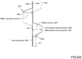
- the operator notices that the tractor 1 has shifted from the scheduled traveling line L2 and steers the second corrector portion 53B at position P21 to increase the right correction amount from zero.
- the right-hand correction is added to the calculated vehicle position W1, and the corrected vehicle position W3 can be made to be substantially the same as the actual position W2.
- the vehicle position of the positioning system 40 can be corrected by the second corrector portion 53B in the direction to eliminate the offset amount W4 that occurred in the vicinity of the position P20.
- the tractor 1 can be steered to the right to bring the actual position W2 of the tractor 1 in line with the scheduled traveling line L2.
- the panel cover 178 supports the display device 45.
- the upper panel portion 178a of the panel cover 178 is provided with a support portion 178e that supports the display device 45.
- the support portion 178e supports the display device 45 in front of the steering shaft 31 and below the steering handle 30.
- the upper plate portion 178a has an attachment surface 178f to which the setter switch 51 and the corrector switch 53 are attached.
- the attachment surface 178f is located behind the support portion 178e and below the steering handle 30.
- the support portion 178e and the attachment surface 178f are continuous, with the support portion 178e located in front of the upper plate portion 178a and the attachment surface 178f located at the rear portion of the upper plate portion 178a.
- the setter switch 51 and corrector switch 53 are mounted on the attachment surface 178f.
- the setter switch 51 and the corrector switch 53 are thereby arranged around the steering shaft 31.
- the setter switch 51 As shown in FIG. 6 , the setter switch 51, the steering changeover switch 52, and the corrector switch 53 are arranged around the steering shaft 31.
- the corrector switch 53 is located on the other side (right side) of the steering shaft 31. More specifically, the corrector switch 53 is disposed on the right side and rearward (diagonally right rearward) of the steering shaft 31. The corrector switch 53 is disposed to the right and rear (diagonally right rear) of the column cover 179 in relation to the column cover 179. The corrector switch 53 is disposed at the right rear portion of the attachment surface 178f in relation to the attachment surface 178f of the panel cover 178. The fact that the corrector switch 53 is disposed at the rear portion of the inclined attachment surface 178f allows for a longer distance between the corrector switch 53 and the steering wheel 30. This can more reliably prevent unintentional operation of the corrector switch 53 and steering wheel 30.
- the tractor 1 is provided with a plurality of controller devices 60.
- the plurality of controller devices 60 are devices that control the traveling system, control the working system, calculate the vehicle position, and the like in the tractor 1.
- the plurality of controller devices 60 are a first controller device 60A, a second controller device 60B, and a third controller device 60C.
- the first controller device 60A receives the satellite signal received by the receiver 41 (received information) and the measurement information (acceleration, angular velocity, and the like) measured by the inertial measurement device 42, and determines the vehicle body position based on the received information and the measurement information. For example, when the correction amount by the corrector switch 53 is zero, that is, the correction of the vehicle position by the corrector switch 53 is not commanded, the first controller device 60A does not correct the calculated vehicle position W1 calculated based on the received information and the measurement information, and determines the calculated vehicle position W1 as the vehicle position to be used for the automatic steering.
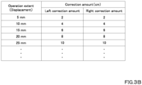
- the first controller device 60A sets the correction amount of the vehicle body position based on either the number of operations of the corrector switch 53 or the amount of operation of the corrector switch 53 (displacement amount), and then determines, as the vehicle position to be used for the automatic steering, the corrected vehicle position W3 obtained by correcting the calculated vehicle body position W1 with the correction amount.
- the first controller device 60A sets a control signal based on the vehicle position (calculated vehicle position W1, corrected body position W3) and the scheduled traveling line L2, and outputs the control signal to the second controller device 60B.
- the second controller device 60B has an automatic steering controller portion 200.
- the automatic steering controller portion 200 includes an electrical and electronic circuit in the second controller device 60B, a computer program stored in a CPU, and the like.
- the automatic steering controller portion 200 controls the steering motor 38 of the automatic steering mechanism 37 so that the vehicle body 3 travels along the scheduled traveling line L2 based on a control signal output from the first controller device 60A.
- the automatic steering controller portion 200 when the deviation between the vehicle position and the scheduled traveling line L2 is less than a threshold value, the automatic steering controller portion 200 maintains the rotation angle of the rotation axis of the steering motor 38.
- the deviation between the vehicle body position and the scheduled traveling line L2 position deviation
- the tractor 1 is located on the left side with respect to the scheduled traveling line L2
- the automatic steering controller portion 200 rotates the rotation axis of the steering motor 38 so that the steering direction of the tractor 1 is in the right direction. That is, the automatic steering controller portion 200 sets the steering angle in the right direction so that the position deviation is zero.
- the steering angle of the steering device 11 is changed based on the deviation between the vehicle body position and the scheduled traveling line L2.
- the orientation of the scheduled traveling line L2 differs from the orientation of the direction of the tractor 1 (vehicle body 3) in the direction of travel (traveling direction) (vehicle body orientation) F1, that is, the vehicle body orientation to the scheduled traveling line L2.
- the automatic steering controller portion 200 may set the steering angle so that the angle ⁇ g becomes zero (vehicle orientation F1 matches the orientation of the scheduled traveling line L2).
- the automatic steering controller portion 200 may also set a final steering angle in the automatic steering based on the steering angle obtained based on the deviation (position deviation) and the steering angle obtained based on the orientation (orientational deviation).
- the setting of the steering angle in the automatic steering in the above-described embodiments is an example and is not limited thereto.
- the controller device 60 changes the control of the automatic steering based on the working device 2 coupled to the vehicle body 3.
- the working device 2 coupled to the vehicle body 3 can be displayed and input by the display device 45.
- the display device 45 displays the registration screen M40 of the working device 2.
- the registration screen M40 displays an information input portion 198 for entering information about the working device 2 (device information).
- the work content of the working device 2 such as tillage, fertilizer splaying, pesticide splaying, harvesting, mowing, tedding, raking, baling and the like, can be inputted into the information input portion 168.
- the registration screen M40 displays a control input portion 199 for entering information about a control parameter (control information).
- the control information is information of a control parameter for obtaining a steering angle when the automatic steering is performed, for example, a value of a control gain G1 or a value corresponding to the control gain G1 can be entered as a control parameter.
- the input of the control gain to the control input portion 199 may be the value of the control gain itself, or instead of the control gain G1, the working load on the ground such as the work field in the working device 2 (a ground work load) may be input in numbers or the like, and then the input ground work load may be converted to the control gain G1.
- the ground work load is a numerical value of the load on the working device 2 when the work is performed on the ground by the working device 2.
- the device information entered into the registration screen M40 and the control information about the control parameters are associated and stored in the storage device 81 provided in the tractor 1, as shown in FIG. 9 . That is, the storage device 81 stores the control parameters entered into the display device 45 and the working device 2 in association with the control parameters entered into the display device 45.
- the automatic steering controller portion 200 has a parameter changer portion 200d, a steering angle calculator portion 200b, and a steering controller portion 200c.
- the parameter changer portion 200d, the steering angle calculator portion 200b, and the steering controller portion 200c include electrical and electronic components provided in the controller device 60, a program incorporated in the controller device 60, and the like.
- the parameter changer portion 200d changes the parameters applied in the automatic steering based on the working device 2. For example, when the work performed by the working device 2 is the chemical spraying, the chemical is often sprayed from above the work field, and when the working device 2 is a chemical sprayer device, the work load on the ground is small because the chemical sprayer device rarely comes into direct contact with the work field. In such a case, when the tractor 1 (vehicle body 3) is steered, the traveling direction of the tractor 1 can easily be changed according to the steering angle. Thus, the parameter changer portion 200d reduces the control gain when the working device 2 is a chemical sprayer device with a low ground work load.
- the parameter changer portion 200d increases the control gain when the working device 2 is a cultivator with a large ground work load.
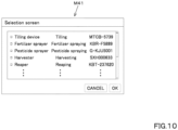
- the display device 45 displays a selection screen M41, as shown in FIG. 10 .
- the selection screen M41 displays a list of device information and control information stored in the storage device 81.
- the value of the control gain G1 corresponding to the selected device information or the value corresponding to the control gain G1 is determined.
- the parameter changer portion 200d sets the control gain G1 to be used during the automatic steering according to the control gain G1 determined on the selection screen M41 or the work load on the ground corresponding to the control gain G1.
- the parameter changer portion 200d changes the control parameter (control gain G1) based on the device information of the working device 2 stored in the storage device 81. For example, when the working device 2 is a tiller, the control gain G1 is set to 1.5, and when the working device 2 is a chemical sprayer device, the control gain G1 is set to 0.8.
- the steering angle calculator portion 200b calculates the steering angle of the steering device 11 to reduce the deviation based on the deviation between the scheduled line L2 and the vehicle body 3 (the position deviation and the orientational deviation) and the parameters.
- the steering angle in the automatic steering is determined based on the position deviation between the vehicle body position (calculated vehicle body position W1 and corrected vehicle position W3) and the scheduled travel line L2, and the control gain G1 determined by the parameter changer portion 200d.
- the steering angle calculator portion 200b determines the steering angle by, for example, multiplying the position deviation by the control gain G1.
- the steering angle calculator portion 200b may use the control gain G1 to determine the steering angle, and the method for calculating the steering angle is not limited thereto.
- the steering angle calculator portion 200b determines the steering angle in the automatic steering based on the orientational deviation between the vehicle orientation and the scheduled traveling line L2 and the control gain G1 determined by the parameter changer portion 200d.
- the steering angle calculator portion 200b obtains the steering angle by, for example, multiplying the orientational deviation by the control gain G1.
- the steering controller portion 200c controls the steering device 11 based on the steering angle (calculated steering angle) calculated by the steering angle calculator portion 200b. As described above, the steering controller portion 200c controls the steering motor 38 so that when the tractor 1 is located on the left side with respect to the scheduled traveling line L2, the steering angle of the tractor 1 in the right direction is the calculated steering angle. The steering controller portion 200c controls the steering motor 38 so that the steering angle of the tractor 1 in the left direction of the tractor 1 is the arithmetic steering angle when the tractor 1 is located on the right side with respect to the scheduled traveling line L2, as described above.
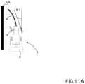
- the control gain G1 is changed by the parameter changer portion 200d, and the steering angle ⁇ 2 in the automatic steering is larger than the steering angle ⁇ 1 in FIG. 11A , as shown in FIG. 11B .
- the steering angle ⁇ 2 is set to a larger steering angle ⁇ 1 than ⁇ 2, it is easier to change the direction of travel of the tractor 1 and to make the travel trajectory K coincide with the planned travel line L2, even when the plowing device enters the ground to a large extent.
- the plowing device and the chemical sprayer device are described, but they are an example and not limited thereto.
- the control gain and other values are an example and are not limited as a matter of course.
- control parameters were changed by inputting and displaying the device and the control information on the display device 45, but instead, the device information and other information may be obtained from the working device 2 in wireless or by other means.
- FIG. 12 shows a block diagram of a modified example of a case where the device information is obtained from working device 2 in wireless or by other means.
- a first communicator device 400 is attached to the working device 2.
- the first communicator device 400 is a device that transmits the device information in wireless and communicates wirelessly by means of communication standards such as Wi-Fi (Wireless Fidelity, registered trademark), RFID tags, BLE (Bluetooth (registered trademark) Low Energy) of the IEEE 802.11 series.
- the first communicator device 400 has a storage portion 400a.
- the storage portion 400a includes, for example, a non-volatile memory or the like, and stores device information such as work content, type, model number, and the like.
- the first communicator device 400 transmits the device information stored in the storage portion 400a to the second communicator device 410 when, for example, there is a request or the like from the second communicator device 410 provided on the vehicle body 3 side.
- the second communicator device 410 is attached to the vehicle body 3.
- the second communicator device 410 is a device is capable of receiving the device information transmitted from the first communicator device 400, and is capable of receiving the device information transmitted from the first communicator device 400, and communicates wirelessly by means of communication standards such as the IEEE 802.11 series Wi-Fi (Wireless Fidelity, registered trademark), RFID tags, BLE (Bluetooth (registered trademark) Low Energy).
- the first communicator device 400 transmits the device information to the second communicator device 410.
- the second communicator device 410 obtains the device information
- the second communicator device 410 outputs the device information to the second controller device 60B.
- the parameter changer portion 200d of the second controller device 60B determines the control gain G1 based on the device information output from the second communicator device 410.
- the parameter changer portion 200d has in advance a control table relating the device information and the control gain G1, and the control gain G1 corresponding to the device information output by the second communicator device 410 is obtained from the control table. That is, the parameter changer portion 200d changes the control gain G1 based on the device information received by the second communicator device 410.
- control parameters were changed based on the device information, but instead, the control parameters may be changed based on the height of the lifter device 8, that is, the height of the lift arm 8a.
- the control parameters may be changed based on the height of the lifter device 8, that is, the height of the lift arm 8a.
- the height of the lift arm 8a tends to be lower, and when the working device 2 is a chemical sprayer device, the height of the lift arm 8a tends to be higher. In other words, it is possible to estimate the working device 2 by the height of the lift arm 8a. As shown in FIG.
- the parameter changer portion 200d has a conversion table showing the relationship between the height of the lift arm 8a and the control gain G1.
- the parameter changer portion 200d refers to the current height of the lift arm 8a and obtains the control gain G1 from the current height of the lift arm 8a and the conversion table.
- the parameter changer portion 200d refers to the current height of the lift arm 8a when switched to the start of the automatic steering by the steering changeover switch 52, and obtains the control gain G1 from the current height of the lift arm 8a and the conversion table.
- the working vehicle 1 is provided with the first communicator portion 400, which is installed in the working device 2 and transmits the device information of the working device 2 to the vehicle body 3, and the second communicator portion 410, which is installed in the vehicle body 3 and can receive the device information transmitted from the first communicator portion 400.
- the parameter changer portion 200d is capable of changing the device information received by the second communicator portion 410.
- the control parameters are changed based on the information. According to this configuration, the device information of the working device 2 connected to the vehicle body 3 can be automatically acquired by the vehicle body 3, and the control parameters corresponding to the working device 2 can be easily set based on the acquired device information.
- the working vehicle 1 has the lifter device 8 having the lift arm 8a to lift and lower the working device 2, and the parameter changer portion 200d changes a control parameter based on the lifting height of the lift arm 8a. According to this configuration, the control parameters can be easily changed by the height of the lift arm 8a.
- the parameter changer portion 200d changes the control gain for calculating the steering angle of the steering device 11 during the automatic steering as the control parameter. According to this configuration, the control gain, which is a control parameter, can easily be used to find the steering angle during the automatic steering.
- the working vehicle 1 is provided with the steering changeover switch 52 for switching either the start or end of automatic steering, and the controller device 60 (second controller device 60B) starts the automatic steering by the steering device 11 when the start of automatic steering is switched with the steering changeover switch 52.
- the controller device 60 second controller device 60B
- the automatic steering can be easily started or ended at the location where one wants to perform the automatic steering.
- the working vehicle 1 is provided with the positioning device 40 capable of detecting the position of the vehicle body 3, the reference line setting switch that sets the position of the vehicle body 3 detected by the positioning device 40 to the start and end positions of the traveling reference line L1.
- the automatic steering controller portion 200 sets the scheduled traveling line L2 based on the traveling reference line L1 at the start of the automatic steering with use of the steering changeover switch 52. According to this configuration, the setting of the traveling reference line L1 can be easily done, and the scheduled traveling line L2 can be easily set by the traveling reference line L1.
Landscapes
- Engineering & Computer Science (AREA)
- Life Sciences & Earth Sciences (AREA)
- Mechanical Engineering (AREA)
- Soil Sciences (AREA)
- Environmental Sciences (AREA)
- Chemical & Material Sciences (AREA)
- Combustion & Propulsion (AREA)
- Transportation (AREA)
- Guiding Agricultural Machines (AREA)
- Steering Control In Accordance With Driving Conditions (AREA)
- Power Steering Mechanism (AREA)
- Lifting Devices For Agricultural Implements (AREA)
Claims (7)
- Ein Arbeitsfahrzeug (1), aufweisend:- eine Lenkeinrichtung (11) zum Lenken eines Fahrzeugkörpers (3);- eine mit dem Fahrzeugkörper (3) verbundene Arbeitseinrichtung (2);- eine automatische Lenk-Steuereinheit (200) zum Durchführen automatischen Lenkens der Lenkeinrichtung (11) basierend auf einem Unterschied zwischen einer geplanten Reiselinie (L2) und einer Position des Fahrzeugkörpers (3);- einen Parameterveränderer (200d) zum Verändern eines Steuerparameters des automatischen Lenkens in Abhängigkeit von der Arbeitseinrichtung (2), welche mit dem Fahrzeugkörper (3) verbunden ist;- eine Hebeeinrichtung (8), mit einem Hebearm (8a) zum Heben der Arbeitseinrichtung (2),dadurch gekennzeichnet, dass, wenn automatisches Lenken durchgeführt wird und ein Lenkwinkel nicht ein Winkel ist, der einem Abbiegen entspricht, der Parameterveränderer (200d) eingerichtet ist, den Steuerparameter basierend auf einer Hebehöhe des Hebearms (8a) zu verändern, wobei der Steuerparameter ein Parameter zur Einholung des Lenkwinkels während des automatischen Lenkens ist.
- Das Arbeitsfahrzeug (1) nach Anspruch 1, aufweisend:- eine Anzeigeeinrichtung (45), in welche ein Verhältnis zwischen der Arbeitseinrichtung (2) und dem Steuerparameter des automatischen Lenkens eingegeben wird, wobei die Anzeigeeinrichtung (45) eingerichtet ist, das Verhältnis anzuzeigen; und- eine Speichereinrichtung (81) zum Speichern des Verhältnisses zwischen dem Steuerparameter und der Arbeitseinrichtung (2), das in die Anzeigeeinrichtung (45) eingegeben wird, wobei- der Parameterveränderer (200d) eingerichtet ist, den Steuerparameter basierend auf dem Verhältnis, welches in der Speichereinrichtung (81) gespeichert ist, zu verändern.
- Das Arbeitsfahrzeug (1) nach Anspruch 1 oder 2, aufweisend:- eine erste Kommunikationseinrichtung (400), welche auf der Arbeitseinrichtung (2) bereitgestellt und eingerichtet ist, Einrichtungsinformationen der Arbeitseinrichtung (2) zu dem Fahrzeugkörper (3) zu übermitteln; und- eine zweite Kommunikationseinrichtung (410), welche auf dem Fahrzeugkörper (3) bereitgestellt und eingerichtet ist, die von der ersten Kommunikationseinrichtung (400) übermittelten Einrichtungsinformationen zu empfangen, wobei- der Parameterveränderer (200d) eingerichtet ist, den Steuerparameter basierend auf den von der zweiten Kommunikationseinrichtung (410) empfangenen Einrichtungsinformationen zu verändern.
- Das Arbeitsfahrzeug (1) nach einem der Ansprüche 1 bis 3, wobei der Parameterveränderer (200d) eingerichtet ist, den Steuerparameter basierend auf einer Bodenarbeitslast zu verändern, welche durch den Arbeitsinhalt der Arbeitseinrichtung (2) ermittelt wird.
- Das Arbeitsfahrzeug (1) nach einem der Ansprüche 1 bis 4, wobei der Parameterveränderer (200d) eingerichtet ist, als Steuerparameter eine Steuerverstärkung zur Berechnung des Lenkwinkels der Lenkeinrichtung (11) bei dem automatischen Lenken zu verändern.
- Das Arbeitsfahrzeug (1) nach einem der Ansprüche 1 bis 5, aufweisend- einen Lenkschalter (52) zum Umschalten des automatischen Lenkens zwischen zu Starten und zu Beenden, wobei- die automatische Lenk-Steuereinheit (200) das automatische Lenken durch die Lenkeinrichtung (11) startet, wenn die Lenk-Steuereinheit (52) das automatische Lenken auf zu Starten umschaltet.
- Das Arbeitsfahrzeug (1) nach Anspruch 6, aufweisend:- eine Positionierungseinrichtung (40) zum Detektieren der Position des Fahrzeugkörpers (3); und- einen Referenzlinienfestlegungsschalter zum Festlegen der Position des Fahrzeugkörpers (3), welche von der Positionierungseinrichtung (40) detektiert wird, zu einer Startposition (P10) und einer Endposition (P11) einer Reisereferenzlinie (L1), wobei- die automatische Lenk-Steuereinheit (200) eingerichtet ist, die geplant Reiselinie (L2) basierend auf der Reisereferenzlinie (L1) festzulegen, wenn der Lenkschalter (52) das automatische Lenken startet.
Applications Claiming Priority (2)
| Application Number | Priority Date | Filing Date | Title |
|---|---|---|---|
| JP2018131239A JP7089965B2 (ja) | 2018-07-11 | 2018-07-11 | 作業車両 |
| PCT/JP2019/024909 WO2020012930A1 (ja) | 2018-07-11 | 2019-06-24 | 作業車両 |
Publications (3)
| Publication Number | Publication Date |
|---|---|
| EP3822148A1 EP3822148A1 (de) | 2021-05-19 |
| EP3822148A4 EP3822148A4 (de) | 2022-04-13 |
| EP3822148B1 true EP3822148B1 (de) | 2024-07-03 |
Family
ID=69142357
Family Applications (1)
| Application Number | Title | Priority Date | Filing Date |
|---|---|---|---|
| EP19835105.8A Active EP3822148B1 (de) | 2018-07-11 | 2019-06-24 | Nutzfahrzeug |
Country Status (6)
| Country | Link |
|---|---|
| US (1) | US11958553B2 (de) |
| EP (1) | EP3822148B1 (de) |
| JP (2) | JP7089965B2 (de) |
| KR (1) | KR102803512B1 (de) |
| CN (1) | CN112384432B (de) |
| WO (1) | WO2020012930A1 (de) |
Families Citing this family (12)
| Publication number | Priority date | Publication date | Assignee | Title |
|---|---|---|---|---|
| US10893642B2 (en) * | 2018-03-15 | 2021-01-19 | Solectrac, Inc. | Agricultural vehicle with bidirectional force exerting electric three-point hitch assemblies |
| JP7089965B2 (ja) * | 2018-07-11 | 2022-06-23 | 株式会社クボタ | 作業車両 |
| JP6766240B1 (ja) * | 2019-09-06 | 2020-10-07 | 株式会社クボタ | 作業車両 |
| JP7502174B2 (ja) | 2020-12-22 | 2024-06-18 | 株式会社クボタ | 農業機械、ならびに農業機械を制御するシステムおよび方法 |
| JP7567630B2 (ja) * | 2021-04-02 | 2024-10-16 | トヨタ自動車株式会社 | 作業車両の制御装置 |
| US12268110B2 (en) * | 2021-07-30 | 2025-04-08 | The Toro Company | Turf aerator |
| JP7600095B2 (ja) * | 2021-12-28 | 2024-12-16 | 株式会社クボタ | 農業機械、農作業支援システム |
| JP7631259B2 (ja) * | 2022-05-24 | 2025-02-18 | 株式会社クボタ | 作業車両の支援システム |
| JP7849257B2 (ja) * | 2022-09-12 | 2026-04-21 | ヤンマーホールディングス株式会社 | 走行制御方法、走行制御システム、及び走行制御プログラム |
| JP7790302B2 (ja) * | 2022-09-16 | 2025-12-23 | 井関農機株式会社 | 作業車両 |
| EP4461622A1 (de) * | 2023-05-09 | 2024-11-13 | Kubota Corporation | Steuerungssystem und steuerungsverfahren für ein arbeitsfahrzeug |
| KR102736560B1 (ko) * | 2023-12-13 | 2024-12-03 | 주식회사 긴트 | 작업차량의 부착기 편차 보정 방법 및 그 장치 |
Family Cites Families (27)
| Publication number | Priority date | Publication date | Assignee | Title |
|---|---|---|---|---|
| JPS5685514U (de) * | 1979-12-03 | 1981-07-09 | ||
| US5092422A (en) * | 1989-12-12 | 1992-03-03 | Clemson University | Multipurpose agricultural tractor |
| JPH0648226A (ja) * | 1991-10-23 | 1994-02-22 | Komatsu Ltd | 作業車両の制御装置 |
| US6711501B2 (en) * | 2000-12-08 | 2004-03-23 | Satloc, Llc | Vehicle navigation system and method for swathing applications |
| US7127340B2 (en) * | 2004-08-17 | 2006-10-24 | Deere & Company | Variable gain logic for a GPS based automatic steering system |
| JP2006232142A (ja) * | 2005-02-25 | 2006-09-07 | Iseki & Co Ltd | 作業車両の旋回制御装置 |
| US7860628B2 (en) * | 2005-06-09 | 2010-12-28 | Trimble Navigation Limited | System for guiding a farm implement between swaths |
| US20080195268A1 (en) * | 2007-02-09 | 2008-08-14 | Novariant, Inc. | Implement control system and method of using same |
| US8060299B2 (en) * | 2007-02-28 | 2011-11-15 | Caterpillar Inc. | Machine with automated steering system |
| US8401744B2 (en) * | 2008-07-22 | 2013-03-19 | Trimble Navigation Limited | System and method for configuring a guidance controller |
| JP2011155938A (ja) * | 2010-02-03 | 2011-08-18 | Daitsu:Kk | 遠隔操作式農業用トラクター |
| CN101833334B (zh) * | 2010-02-09 | 2011-09-21 | 北京农业信息技术研究中心 | 拖拉机自动导航控制系统及其方法 |
| CA2783807C (en) * | 2011-09-22 | 2015-03-31 | Philip J. Otto | Swather tractor with rear wheel active steering |
| EP2832568B1 (de) * | 2012-03-28 | 2019-11-27 | Kubota Corporation | Hybridnutzfahrzeug |
| JP2016021890A (ja) * | 2014-07-17 | 2016-02-08 | 株式会社クボタ | 植播系圃場作業機及びそれに用いられる自動操舵システム |
| EP3147180B1 (de) * | 2015-09-25 | 2020-02-19 | Siemens Mobility S.A.S. | Assistenzsystem und -verfahren zum lenken für fahrzeug |
| JP6576237B2 (ja) * | 2015-12-25 | 2019-09-18 | 株式会社クボタ | 作業車 |
| CN119631665A (zh) * | 2015-12-25 | 2025-03-18 | 株式会社久保田 | 作业车 |
| JP6643091B2 (ja) * | 2016-01-13 | 2020-02-12 | 株式会社クボタ | 農作業機 |
| US9702115B1 (en) * | 2016-01-08 | 2017-07-11 | Caterpillar Inc. | Autonomous method for detecting a pile |
| JP6525902B2 (ja) * | 2016-03-03 | 2019-06-05 | 株式会社クボタ | 圃場作業車両 |
| US10144453B2 (en) * | 2016-04-13 | 2018-12-04 | Cnh Industrial America Llc | System and method for controlling a vehicle |
| KR101854661B1 (ko) | 2016-04-29 | 2018-05-04 | 삼성중공업 주식회사 | 누설 검출 장치 |
| US10087603B2 (en) * | 2016-09-28 | 2018-10-02 | Caterpillar Inc. | Stability control system for machine in motion |
| US10377365B2 (en) * | 2017-11-13 | 2019-08-13 | Iseki & Co., Ltd. | Work vehicle |
| CN110843907B (zh) * | 2017-12-11 | 2021-03-23 | 中联农业机械股份有限公司 | 一种基于分块的作业区域路径规划方法及装置 |
| JP7089965B2 (ja) * | 2018-07-11 | 2022-06-23 | 株式会社クボタ | 作業車両 |
-
2018
- 2018-07-11 JP JP2018131239A patent/JP7089965B2/ja active Active
-
2019
- 2019-06-24 KR KR1020207031094A patent/KR102803512B1/ko active Active
- 2019-06-24 WO PCT/JP2019/024909 patent/WO2020012930A1/ja not_active Ceased
- 2019-06-24 EP EP19835105.8A patent/EP3822148B1/de active Active
- 2019-06-24 CN CN201980046376.7A patent/CN112384432B/zh active Active
-
2021
- 2021-01-05 US US17/141,266 patent/US11958553B2/en active Active
-
2022
- 2022-06-13 JP JP2022095195A patent/JP7358566B2/ja active Active
Also Published As
| Publication number | Publication date |
|---|---|
| KR102803512B1 (ko) | 2025-05-08 |
| US11958553B2 (en) | 2024-04-16 |
| CN112384432B (zh) | 2023-03-28 |
| JP7089965B2 (ja) | 2022-06-23 |
| EP3822148A1 (de) | 2021-05-19 |
| EP3822148A4 (de) | 2022-04-13 |
| WO2020012930A1 (ja) | 2020-01-16 |
| JP7358566B2 (ja) | 2023-10-10 |
| CN112384432A (zh) | 2021-02-19 |
| JP2022125058A (ja) | 2022-08-26 |
| JP2020005595A (ja) | 2020-01-16 |
| US20210146995A1 (en) | 2021-05-20 |
| KR20210030255A (ko) | 2021-03-17 |
Similar Documents
| Publication | Publication Date | Title |
|---|---|---|
| EP3822148B1 (de) | Nutzfahrzeug | |
| EP3811749B1 (de) | Nutzfahrzeug | |
| US11800828B2 (en) | Working vehicle | |
| US20210105929A1 (en) | Working vehicle | |
| EP4026416B1 (de) | Nutzfahrzeug | |
| US11917933B2 (en) | Working vehicle | |
| JP7106419B2 (ja) | 作業車両 | |
| JP2022164924A (ja) | 作業車両 | |
| US20220108566A1 (en) | Working vehicle | |
| JP7059123B2 (ja) | 作業車両 | |
| JP7132812B2 (ja) | 作業車両 | |
| JP7059122B2 (ja) | 作業車両 | |
| JP7163178B2 (ja) | 作業車両 | |
| JP7179565B2 (ja) | 作業車両 | |
| JP7125206B2 (ja) | 作業車両 |
Legal Events
| Date | Code | Title | Description |
|---|---|---|---|
| STAA | Information on the status of an ep patent application or granted ep patent |
Free format text: STATUS: THE INTERNATIONAL PUBLICATION HAS BEEN MADE |
|
| PUAI | Public reference made under article 153(3) epc to a published international application that has entered the european phase |
Free format text: ORIGINAL CODE: 0009012 |
|
| STAA | Information on the status of an ep patent application or granted ep patent |
Free format text: STATUS: REQUEST FOR EXAMINATION WAS MADE |
|
| 17P | Request for examination filed |
Effective date: 20201228 |
|
| AK | Designated contracting states |
Kind code of ref document: A1 Designated state(s): AL AT BE BG CH CY CZ DE DK EE ES FI FR GB GR HR HU IE IS IT LI LT LU LV MC MK MT NL NO PL PT RO RS SE SI SK SM TR |
|
| DAV | Request for validation of the european patent (deleted) | ||
| DAX | Request for extension of the european patent (deleted) | ||
| A4 | Supplementary search report drawn up and despatched |
Effective date: 20220314 |
|
| RIC1 | Information provided on ipc code assigned before grant |
Ipc: B62D 15/02 20060101ALN20220308BHEP Ipc: A01B 63/10 20060101ALN20220308BHEP Ipc: A01B 69/04 20060101ALI20220308BHEP Ipc: A01B 69/00 20060101AFI20220308BHEP |
|
| REG | Reference to a national code |
Ref country code: DE Ref legal event code: R079 Free format text: PREVIOUS MAIN CLASS: B62D0006000000 Ipc: A01B0069000000 Ref country code: DE Ref legal event code: R079 Ref document number: 602019054730 Country of ref document: DE Free format text: PREVIOUS MAIN CLASS: B62D0006000000 Ipc: A01B0069000000 |
|
| GRAP | Despatch of communication of intention to grant a patent |
Free format text: ORIGINAL CODE: EPIDOSNIGR1 |
|
| STAA | Information on the status of an ep patent application or granted ep patent |
Free format text: STATUS: GRANT OF PATENT IS INTENDED |
|
| RIC1 | Information provided on ipc code assigned before grant |
Ipc: B62D 15/02 20060101ALN20240206BHEP Ipc: A01B 63/10 20060101ALN20240206BHEP Ipc: A01B 69/04 20060101ALI20240206BHEP Ipc: A01B 69/00 20060101AFI20240206BHEP |
|
| RIC1 | Information provided on ipc code assigned before grant |
Ipc: B62D 15/02 20060101ALN20240209BHEP Ipc: A01B 63/10 20060101ALN20240209BHEP Ipc: A01B 69/04 20060101ALI20240209BHEP Ipc: A01B 69/00 20060101AFI20240209BHEP |
|
| INTG | Intention to grant announced |
Effective date: 20240305 |
|
| GRAS | Grant fee paid |
Free format text: ORIGINAL CODE: EPIDOSNIGR3 |
|
| GRAA | (expected) grant |
Free format text: ORIGINAL CODE: 0009210 |
|
| STAA | Information on the status of an ep patent application or granted ep patent |
Free format text: STATUS: THE PATENT HAS BEEN GRANTED |
|
| P01 | Opt-out of the competence of the unified patent court (upc) registered |
Effective date: 20240506 |
|
| AK | Designated contracting states |
Kind code of ref document: B1 Designated state(s): AL AT BE BG CH CY CZ DE DK EE ES FI FR GB GR HR HU IE IS IT LI LT LU LV MC MK MT NL NO PL PT RO RS SE SI SK SM TR |
|
| REG | Reference to a national code |
Ref country code: CH Ref legal event code: EP |
|
| REG | Reference to a national code |
Ref country code: DE Ref legal event code: R096 Ref document number: 602019054730 Country of ref document: DE |
|
| REG | Reference to a national code |
Ref country code: LT Ref legal event code: MG9D |
|
| REG | Reference to a national code |
Ref country code: NL Ref legal event code: MP Effective date: 20240703 |
|
| PG25 | Lapsed in a contracting state [announced via postgrant information from national office to epo] |
Ref country code: PT Free format text: LAPSE BECAUSE OF FAILURE TO SUBMIT A TRANSLATION OF THE DESCRIPTION OR TO PAY THE FEE WITHIN THE PRESCRIBED TIME-LIMIT Effective date: 20241104 |
|
| REG | Reference to a national code |
Ref country code: AT Ref legal event code: MK05 Ref document number: 1698788 Country of ref document: AT Kind code of ref document: T Effective date: 20240703 |
|
| PG25 | Lapsed in a contracting state [announced via postgrant information from national office to epo] |
Ref country code: NL Free format text: LAPSE BECAUSE OF FAILURE TO SUBMIT A TRANSLATION OF THE DESCRIPTION OR TO PAY THE FEE WITHIN THE PRESCRIBED TIME-LIMIT Effective date: 20240703 |
|
| PG25 | Lapsed in a contracting state [announced via postgrant information from national office to epo] |
Ref country code: PT Free format text: LAPSE BECAUSE OF FAILURE TO SUBMIT A TRANSLATION OF THE DESCRIPTION OR TO PAY THE FEE WITHIN THE PRESCRIBED TIME-LIMIT Effective date: 20241104 Ref country code: NL Free format text: LAPSE BECAUSE OF FAILURE TO SUBMIT A TRANSLATION OF THE DESCRIPTION OR TO PAY THE FEE WITHIN THE PRESCRIBED TIME-LIMIT Effective date: 20240703 |
|
| PG25 | Lapsed in a contracting state [announced via postgrant information from national office to epo] |
Ref country code: NO Free format text: LAPSE BECAUSE OF FAILURE TO SUBMIT A TRANSLATION OF THE DESCRIPTION OR TO PAY THE FEE WITHIN THE PRESCRIBED TIME-LIMIT Effective date: 20241003 |
|
| PG25 | Lapsed in a contracting state [announced via postgrant information from national office to epo] |
Ref country code: FI Free format text: LAPSE BECAUSE OF FAILURE TO SUBMIT A TRANSLATION OF THE DESCRIPTION OR TO PAY THE FEE WITHIN THE PRESCRIBED TIME-LIMIT Effective date: 20240703 Ref country code: PL Free format text: LAPSE BECAUSE OF FAILURE TO SUBMIT A TRANSLATION OF THE DESCRIPTION OR TO PAY THE FEE WITHIN THE PRESCRIBED TIME-LIMIT Effective date: 20240703 Ref country code: GR Free format text: LAPSE BECAUSE OF FAILURE TO SUBMIT A TRANSLATION OF THE DESCRIPTION OR TO PAY THE FEE WITHIN THE PRESCRIBED TIME-LIMIT Effective date: 20241004 |
|
| PG25 | Lapsed in a contracting state [announced via postgrant information from national office to epo] |
Ref country code: BG Free format text: LAPSE BECAUSE OF FAILURE TO SUBMIT A TRANSLATION OF THE DESCRIPTION OR TO PAY THE FEE WITHIN THE PRESCRIBED TIME-LIMIT Effective date: 20240703 |
|
| PG25 | Lapsed in a contracting state [announced via postgrant information from national office to epo] |
Ref country code: LV Free format text: LAPSE BECAUSE OF FAILURE TO SUBMIT A TRANSLATION OF THE DESCRIPTION OR TO PAY THE FEE WITHIN THE PRESCRIBED TIME-LIMIT Effective date: 20240703 |
|
| PG25 | Lapsed in a contracting state [announced via postgrant information from national office to epo] |
Ref country code: IS Free format text: LAPSE BECAUSE OF FAILURE TO SUBMIT A TRANSLATION OF THE DESCRIPTION OR TO PAY THE FEE WITHIN THE PRESCRIBED TIME-LIMIT Effective date: 20241103 Ref country code: AT Free format text: LAPSE BECAUSE OF FAILURE TO SUBMIT A TRANSLATION OF THE DESCRIPTION OR TO PAY THE FEE WITHIN THE PRESCRIBED TIME-LIMIT Effective date: 20240703 |
|
| PG25 | Lapsed in a contracting state [announced via postgrant information from national office to epo] |
Ref country code: CZ Free format text: LAPSE BECAUSE OF FAILURE TO SUBMIT A TRANSLATION OF THE DESCRIPTION OR TO PAY THE FEE WITHIN THE PRESCRIBED TIME-LIMIT Effective date: 20240703 Ref country code: HR Free format text: LAPSE BECAUSE OF FAILURE TO SUBMIT A TRANSLATION OF THE DESCRIPTION OR TO PAY THE FEE WITHIN THE PRESCRIBED TIME-LIMIT Effective date: 20240703 |
|
| PG25 | Lapsed in a contracting state [announced via postgrant information from national office to epo] |
Ref country code: RS Free format text: LAPSE BECAUSE OF FAILURE TO SUBMIT A TRANSLATION OF THE DESCRIPTION OR TO PAY THE FEE WITHIN THE PRESCRIBED TIME-LIMIT Effective date: 20241003 Ref country code: ES Free format text: LAPSE BECAUSE OF FAILURE TO SUBMIT A TRANSLATION OF THE DESCRIPTION OR TO PAY THE FEE WITHIN THE PRESCRIBED TIME-LIMIT Effective date: 20240703 |
|
| PG25 | Lapsed in a contracting state [announced via postgrant information from national office to epo] |
Ref country code: RS Free format text: LAPSE BECAUSE OF FAILURE TO SUBMIT A TRANSLATION OF THE DESCRIPTION OR TO PAY THE FEE WITHIN THE PRESCRIBED TIME-LIMIT Effective date: 20241003 Ref country code: PL Free format text: LAPSE BECAUSE OF FAILURE TO SUBMIT A TRANSLATION OF THE DESCRIPTION OR TO PAY THE FEE WITHIN THE PRESCRIBED TIME-LIMIT Effective date: 20240703 Ref country code: NO Free format text: LAPSE BECAUSE OF FAILURE TO SUBMIT A TRANSLATION OF THE DESCRIPTION OR TO PAY THE FEE WITHIN THE PRESCRIBED TIME-LIMIT Effective date: 20241003 Ref country code: LV Free format text: LAPSE BECAUSE OF FAILURE TO SUBMIT A TRANSLATION OF THE DESCRIPTION OR TO PAY THE FEE WITHIN THE PRESCRIBED TIME-LIMIT Effective date: 20240703 Ref country code: IS Free format text: LAPSE BECAUSE OF FAILURE TO SUBMIT A TRANSLATION OF THE DESCRIPTION OR TO PAY THE FEE WITHIN THE PRESCRIBED TIME-LIMIT Effective date: 20241103 Ref country code: HR Free format text: LAPSE BECAUSE OF FAILURE TO SUBMIT A TRANSLATION OF THE DESCRIPTION OR TO PAY THE FEE WITHIN THE PRESCRIBED TIME-LIMIT Effective date: 20240703 Ref country code: GR Free format text: LAPSE BECAUSE OF FAILURE TO SUBMIT A TRANSLATION OF THE DESCRIPTION OR TO PAY THE FEE WITHIN THE PRESCRIBED TIME-LIMIT Effective date: 20241004 Ref country code: FI Free format text: LAPSE BECAUSE OF FAILURE TO SUBMIT A TRANSLATION OF THE DESCRIPTION OR TO PAY THE FEE WITHIN THE PRESCRIBED TIME-LIMIT Effective date: 20240703 Ref country code: ES Free format text: LAPSE BECAUSE OF FAILURE TO SUBMIT A TRANSLATION OF THE DESCRIPTION OR TO PAY THE FEE WITHIN THE PRESCRIBED TIME-LIMIT Effective date: 20240703 Ref country code: CZ Free format text: LAPSE BECAUSE OF FAILURE TO SUBMIT A TRANSLATION OF THE DESCRIPTION OR TO PAY THE FEE WITHIN THE PRESCRIBED TIME-LIMIT Effective date: 20240703 Ref country code: BG Free format text: LAPSE BECAUSE OF FAILURE TO SUBMIT A TRANSLATION OF THE DESCRIPTION OR TO PAY THE FEE WITHIN THE PRESCRIBED TIME-LIMIT Effective date: 20240703 Ref country code: AT Free format text: LAPSE BECAUSE OF FAILURE TO SUBMIT A TRANSLATION OF THE DESCRIPTION OR TO PAY THE FEE WITHIN THE PRESCRIBED TIME-LIMIT Effective date: 20240703 |
|
| REG | Reference to a national code |
Ref country code: DE Ref legal event code: R097 Ref document number: 602019054730 Country of ref document: DE |
|
| PG25 | Lapsed in a contracting state [announced via postgrant information from national office to epo] |
Ref country code: RO Free format text: LAPSE BECAUSE OF FAILURE TO SUBMIT A TRANSLATION OF THE DESCRIPTION OR TO PAY THE FEE WITHIN THE PRESCRIBED TIME-LIMIT Effective date: 20240703 Ref country code: DK Free format text: LAPSE BECAUSE OF FAILURE TO SUBMIT A TRANSLATION OF THE DESCRIPTION OR TO PAY THE FEE WITHIN THE PRESCRIBED TIME-LIMIT Effective date: 20240703 Ref country code: SM Free format text: LAPSE BECAUSE OF FAILURE TO SUBMIT A TRANSLATION OF THE DESCRIPTION OR TO PAY THE FEE WITHIN THE PRESCRIBED TIME-LIMIT Effective date: 20240703 |
|
| PG25 | Lapsed in a contracting state [announced via postgrant information from national office to epo] |
Ref country code: EE Free format text: LAPSE BECAUSE OF FAILURE TO SUBMIT A TRANSLATION OF THE DESCRIPTION OR TO PAY THE FEE WITHIN THE PRESCRIBED TIME-LIMIT Effective date: 20240703 |
|
| PG25 | Lapsed in a contracting state [announced via postgrant information from national office to epo] |
Ref country code: IT Free format text: LAPSE BECAUSE OF FAILURE TO SUBMIT A TRANSLATION OF THE DESCRIPTION OR TO PAY THE FEE WITHIN THE PRESCRIBED TIME-LIMIT Effective date: 20240703 Ref country code: SK Free format text: LAPSE BECAUSE OF FAILURE TO SUBMIT A TRANSLATION OF THE DESCRIPTION OR TO PAY THE FEE WITHIN THE PRESCRIBED TIME-LIMIT Effective date: 20240703 |
|
| PLBE | No opposition filed within time limit |
Free format text: ORIGINAL CODE: 0009261 |
|
| STAA | Information on the status of an ep patent application or granted ep patent |
Free format text: STATUS: NO OPPOSITION FILED WITHIN TIME LIMIT |
|
| 26N | No opposition filed |
Effective date: 20250404 |
|
| PGFP | Annual fee paid to national office [announced via postgrant information from national office to epo] |
Ref country code: DE Payment date: 20250429 Year of fee payment: 7 |
|
| PGFP | Annual fee paid to national office [announced via postgrant information from national office to epo] |
Ref country code: FR Payment date: 20250508 Year of fee payment: 7 |
|
| PG25 | Lapsed in a contracting state [announced via postgrant information from national office to epo] |
Ref country code: SE Free format text: LAPSE BECAUSE OF FAILURE TO SUBMIT A TRANSLATION OF THE DESCRIPTION OR TO PAY THE FEE WITHIN THE PRESCRIBED TIME-LIMIT Effective date: 20240703 |
|
| REG | Reference to a national code |
Ref country code: CH Ref legal event code: H13 Free format text: ST27 STATUS EVENT CODE: U-0-0-H10-H13 (AS PROVIDED BY THE NATIONAL OFFICE) Effective date: 20260127 |
|
| PG25 | Lapsed in a contracting state [announced via postgrant information from national office to epo] |
Ref country code: MC Free format text: LAPSE BECAUSE OF FAILURE TO SUBMIT A TRANSLATION OF THE DESCRIPTION OR TO PAY THE FEE WITHIN THE PRESCRIBED TIME-LIMIT Effective date: 20240703 |
|
| PG25 | Lapsed in a contracting state [announced via postgrant information from national office to epo] |
Ref country code: LU Free format text: LAPSE BECAUSE OF NON-PAYMENT OF DUE FEES Effective date: 20250624 |
|
| GBPC | Gb: european patent ceased through non-payment of renewal fee |
Effective date: 20250624 |
|
| REG | Reference to a national code |
Ref country code: BE Ref legal event code: MM Effective date: 20250630 |
|
| PG25 | Lapsed in a contracting state [announced via postgrant information from national office to epo] |
Ref country code: GB Free format text: LAPSE BECAUSE OF NON-PAYMENT OF DUE FEES Effective date: 20250624 |
|
| PG25 | Lapsed in a contracting state [announced via postgrant information from national office to epo] |
Ref country code: IE Free format text: LAPSE BECAUSE OF NON-PAYMENT OF DUE FEES Effective date: 20250624 |
|
| PG25 | Lapsed in a contracting state [announced via postgrant information from national office to epo] |
Ref country code: BE Free format text: LAPSE BECAUSE OF NON-PAYMENT OF DUE FEES Effective date: 20250630 |