EP3822084A1 - Tintenstrahldrucker und tintenstrahldruckverfahren - Google Patents
Tintenstrahldrucker und tintenstrahldruckverfahren Download PDFInfo
- Publication number
- EP3822084A1 EP3822084A1 EP20206661.9A EP20206661A EP3822084A1 EP 3822084 A1 EP3822084 A1 EP 3822084A1 EP 20206661 A EP20206661 A EP 20206661A EP 3822084 A1 EP3822084 A1 EP 3822084A1
- Authority
- EP
- European Patent Office
- Prior art keywords
- ink
- air
- ink ejection
- transport path
- base material
- Prior art date
- Legal status (The legal status is an assumption and is not a legal conclusion. Google has not performed a legal analysis and makes no representation as to the accuracy of the status listed.)
- Granted
Links
- 238000000034 method Methods 0.000 title description 17
- 238000007641 inkjet printing Methods 0.000 title 1
- 239000000463 material Substances 0.000 claims abstract description 103
- 230000007723 transport mechanism Effects 0.000 claims abstract description 9
- 230000000149 penetrating effect Effects 0.000 claims abstract description 6
- 238000011144 upstream manufacturing Methods 0.000 claims description 31
- 239000000976 ink Substances 0.000 description 160
- 239000003595 mist Substances 0.000 description 36
- 230000008569 process Effects 0.000 description 13
- 238000007639 printing Methods 0.000 description 9
- 239000003566 sealing material Substances 0.000 description 9
- 239000011261 inert gas Substances 0.000 description 7
- 230000007246 mechanism Effects 0.000 description 7
- 230000003068 static effect Effects 0.000 description 5
- 230000015572 biosynthetic process Effects 0.000 description 3
- 238000007667 floating Methods 0.000 description 3
- 230000004048 modification Effects 0.000 description 3
- 238000012986 modification Methods 0.000 description 3
- 230000009467 reduction Effects 0.000 description 3
- 238000004804 winding Methods 0.000 description 3
- IJGRMHOSHXDMSA-UHFFFAOYSA-N Atomic nitrogen Chemical compound N#N IJGRMHOSHXDMSA-UHFFFAOYSA-N 0.000 description 2
- 230000008901 benefit Effects 0.000 description 2
- 238000004590 computer program Methods 0.000 description 2
- 239000000498 cooling water Substances 0.000 description 2
- 238000010586 diagram Methods 0.000 description 2
- 229910001873 dinitrogen Inorganic materials 0.000 description 2
- 230000005611 electricity Effects 0.000 description 2
- 230000008859 change Effects 0.000 description 1
- 238000004140 cleaning Methods 0.000 description 1
- 239000003086 colorant Substances 0.000 description 1
- 230000003247 decreasing effect Effects 0.000 description 1
- 238000005516 engineering process Methods 0.000 description 1
- 230000006870 function Effects 0.000 description 1
- 239000004615 ingredient Substances 0.000 description 1
- 239000003999 initiator Substances 0.000 description 1
- 230000001678 irradiating effect Effects 0.000 description 1
- 239000000203 mixture Substances 0.000 description 1
- 238000000746 purification Methods 0.000 description 1
- XLYOFNOQVPJJNP-UHFFFAOYSA-N water Substances O XLYOFNOQVPJJNP-UHFFFAOYSA-N 0.000 description 1
- 230000037303 wrinkles Effects 0.000 description 1
Images


Classifications
-
- B—PERFORMING OPERATIONS; TRANSPORTING
- B41—PRINTING; LINING MACHINES; TYPEWRITERS; STAMPS
- B41J—TYPEWRITERS; SELECTIVE PRINTING MECHANISMS, i.e. MECHANISMS PRINTING OTHERWISE THAN FROM A FORME; CORRECTION OF TYPOGRAPHICAL ERRORS
- B41J29/00—Details of, or accessories for, typewriters or selective printing mechanisms not otherwise provided for
- B41J29/377—Cooling or ventilating arrangements
-
- B—PERFORMING OPERATIONS; TRANSPORTING
- B41—PRINTING; LINING MACHINES; TYPEWRITERS; STAMPS
- B41J—TYPEWRITERS; SELECTIVE PRINTING MECHANISMS, i.e. MECHANISMS PRINTING OTHERWISE THAN FROM A FORME; CORRECTION OF TYPOGRAPHICAL ERRORS
- B41J2/00—Typewriters or selective printing mechanisms characterised by the printing or marking process for which they are designed
- B41J2/005—Typewriters or selective printing mechanisms characterised by the printing or marking process for which they are designed characterised by bringing liquid or particles selectively into contact with a printing material
- B41J2/01—Ink jet
- B41J2/135—Nozzles
- B41J2/165—Prevention or detection of nozzle clogging, e.g. cleaning, capping or moistening for nozzles
- B41J2/16517—Cleaning of print head nozzles
- B41J2/16552—Cleaning of print head nozzles using cleaning fluids
-
- B—PERFORMING OPERATIONS; TRANSPORTING
- B41—PRINTING; LINING MACHINES; TYPEWRITERS; STAMPS
- B41J—TYPEWRITERS; SELECTIVE PRINTING MECHANISMS, i.e. MECHANISMS PRINTING OTHERWISE THAN FROM A FORME; CORRECTION OF TYPOGRAPHICAL ERRORS
- B41J2/00—Typewriters or selective printing mechanisms characterised by the printing or marking process for which they are designed
- B41J2/005—Typewriters or selective printing mechanisms characterised by the printing or marking process for which they are designed characterised by bringing liquid or particles selectively into contact with a printing material
- B41J2/01—Ink jet
- B41J2/17—Ink jet characterised by ink handling
- B41J2/1714—Conditioning of the outside of ink supply systems, e.g. inkjet collector cleaning, ink mist removal
-
- B—PERFORMING OPERATIONS; TRANSPORTING
- B41—PRINTING; LINING MACHINES; TYPEWRITERS; STAMPS
- B41J—TYPEWRITERS; SELECTIVE PRINTING MECHANISMS, i.e. MECHANISMS PRINTING OTHERWISE THAN FROM A FORME; CORRECTION OF TYPOGRAPHICAL ERRORS
- B41J2/00—Typewriters or selective printing mechanisms characterised by the printing or marking process for which they are designed
- B41J2/005—Typewriters or selective printing mechanisms characterised by the printing or marking process for which they are designed characterised by bringing liquid or particles selectively into contact with a printing material
- B41J2/01—Ink jet
- B41J2/135—Nozzles
- B41J2/165—Prevention or detection of nozzle clogging, e.g. cleaning, capping or moistening for nozzles
- B41J2/16517—Cleaning of print head nozzles
- B41J2/16552—Cleaning of print head nozzles using cleaning fluids
- B41J2002/16555—Air or gas for cleaning
-
- B—PERFORMING OPERATIONS; TRANSPORTING
- B41—PRINTING; LINING MACHINES; TYPEWRITERS; STAMPS
- B41J—TYPEWRITERS; SELECTIVE PRINTING MECHANISMS, i.e. MECHANISMS PRINTING OTHERWISE THAN FROM A FORME; CORRECTION OF TYPOGRAPHICAL ERRORS
- B41J2202/00—Embodiments of or processes related to ink-jet or thermal heads
- B41J2202/01—Embodiments of or processes related to ink-jet heads
- B41J2202/20—Modules
Definitions
- the present invention relates to a technique for printing based on ink-jet technology.
- ink mist is generated in an ink-jet printer when minute ink droplets are ejected toward a base material. If the ink mist adheres to and accumulates on the interior of the printer, for example, around ink ejection ports, the ink mist can become large ink droplets which in turn fall on the base material. This can become a factor in reducing printing quality.
- Japanese Patent Application Laid-Open No. 2015-134496 discloses the provision of an ink mist collection unit in a location downstream of a recording head as seen in the transport direction of the base material.
- the ink mist collection unit includes a sucking port opposed to the base material to suck in air present above the base material together with the ink mist through the sucking port.
- an ink-jet printer comprises: a base material transport mechanism for transporting a base material along a transport path in a transport direction; at least one ink ejection head having a lower surface opposed to the transport path over the transport path, and an ink ejection port open toward the transport path in the lower surface and for ejecting ink toward the transport path; and a base plate having an opposite surface opposed to the transport path over the transport path, and at least one mounting hole open in the opposite surface, the ink ejection head being mounted in the mounting hole, the base plate including an air flow hole that is a though hole penetrating through the base plate, the air flow hole having at least one air outlet open in a location downstream of the ink ejection port in the opposite surface, wherein air passing through the air flow hole is ejected from the air outlet toward the transport path.
- Ink mist generated in the ink ejection port is caused to adhere to the base material by a downflow of air ejected from the air outlet downstream of the ink ejection port. This reduces the adhesion of the ink mist to the base plate. Also, the ink mist is removed by the provision of the air flow hole and the air outlet in the base plate to which the ink ejection head is mounted. This achieves the reduction in size of the printer, as compared with the provision of a mechanism for sucking in the ink mist.
- the air flow hole is formed by an outer surface of the ink ejection head disposed inside the mounting hole and an inner surface of the mounting hole.
- the ink-jet printer in which the air flow hole is formed by the outer surface of the ink ejection head and the inner surface of the mounting hole, allows the air outlet to be provided in a position immediately adjacent to a downstream portion of the ink ejection head. This reduces the ink mist adhering to the base plate supporting the ink ejection head after being generated in the ink ejection port of the ink ejection head.
- a distance between the opposite surface and the transport path in a location downstream of the air outlet is greater than a distance between the opposite surface or the lower surface and the transport path in a location upstream of the air outlet.
- An air flow directed downstream from the air outlet is easily formed because the distance between the opposite surface and the transport path in a location downstream of the air outlet is greater than the distance between the opposite surface or the lower surface and the transport path in a location upstream of the air outlet. This allows the ink mist to move downstream of the air outlet.
- the ink-j et printer further comprises an air supply unit provided at the upper side of the base plate and for supplying air directed toward the air outlet to the air flow hole.
- the supply of air directed toward the air outlet to the air flow hole from over the base plate allows the air to be ejected from the air outlet.
- the air supply unit supplies air to an outer surface of the ink ejection head.
- the supply of air to the outer surface of the ink ejection head allows the ink ejection head to cool.
- the at least one mounting hole in the base plate includes a plurality of mounting holes
- the at least one ink ejection head includes a plurality of ink ejection heads.
- the ink ejection heads are mounted in the respective mounting holes.
- the at least one air outlet includes a plurality of air outlets.
- the base plate includes the air outlets positioned downstream of the ink ejection ports of the respective ink ejection heads.
- the ink mist generated in the ink ejection heads are restrained from adhering to the base plate because the air outlets are provided downstream of the ink ejection heads.
- the amount of air ejected from a downstream one of the air outlets is less than the amount of air ejected from an upstream one of the air outlets.
- the amount of air ejected from the downstream air outlet is less than the amount of air ejected from the upstream air outlet, whereby a flow of air directed downstream is easily formed over the base material.
- the ink-jet printer further comprises an air-permeable filter member positioned in the air flow hole.
- the air-permeable filter member disposed in the air flow hole allows the adjustment of the amount of air ejected from the air outlet.
- a gap of the air flow hole in the transport direction is smaller than a distance between the opposite surface and the transport path in a location downstream of the air outlet.
- Fig. 1 is a diagram schematically showing a configuration of an ink-jet printer 1 according to a first preferred embodiment of the present invention.
- the ink-jet printer 1 is an apparatus for printing an image on a recording surface 9a of a strip-shaped base material 9 (e.g., printing paper) by ejecting ink droplets from a plurality of ink ejection heads 21 while transporting the base material 9.
- a strip-shaped base material 9 e.g., printing paper
- Ultraviolet curable inks which are cured when irradiated with ultraviolet rays that are electromagnetic waves are used in the ink-jet printer 1.
- the ultraviolet curable inks can contain a curing initiator for accelerating the curing as an ingredient.
- Inks e.g., water-based inks or oil-based inks
- an irradiator 70 described later may be ommited.
- the ink-jet printer 1 includes a base material transport mechanism 10, an image recording unit 20, a support unit 30, a process chamber 40, an inert gas supply unit 50, an irradiator 70, and a controller 80.
- the components (including the image recording unit 20 and the process chamber 40) other than the controller 80 are housed in a box-like casing 90.
- the base material transport mechanism 10 is a mechanism for transporting the base material 9 in a direction extending along the length of the base material 9.
- the base material transport mechanism 10 includes an unwinding unit 11, a plurality of transport rollers 12, a chill roller 13, and a winding unit 14.
- the transport rollers 12 include a direction switching roller 121 and nip rollers 122 to be described later.
- the base material 9 is unwound from the unwinding unit 11, and is transported along a transport path formed by the transport rollers 12.
- Each of the transport rollers 12 rotates about a horizontal axis to guide the base material 9 downstream in the direction of movement of the base material 9.
- the transported base material 9 is wound and collected on the winding unit 14. In this manner, the base material 9 is transported along a fixed transport path TR by being supported by the transport rollers 12, the chill roller 13, and the like which are disposed in fixed positions.
- the direction in which the base material 9 moves along the transport path TR is referred to simply as a "transport direction”.
- the term “downstream” as simply used herein refers to being downstream as seen in the direction of movement of the base material 9
- the term “upstream” as simply used herein refers to being upstream as seen in the direction of movement of the base material 9.
- a direction orthogonal to the direction of movement of the base material 9 and parallel to a surface of the base material 9 is referred to as a "width direction”.
- the base material 9 initially passes through a cleaner 15 after being unwound from the unwinding unit 11.
- the cleaner 15 includes a plurality of suction rolls 151 disposed vertically in proximity to each other.
- the suction rolls 151 rotate while contacting the recording surface 9a and a back surface 9b of the base material 9. Foreign materials adhering to the recording surface 9a and the back surface 9b are removed by suction by the suction rolls 151. This reduces the number of foreign materials adhering to the base material 9 before printing to accordingly reduce printing failures such as ink rejected or exuded by the foreign materials.
- the cleaner 15 may be of other types such as sucking mechanism as an example than the suction rolls 151.
- the base material 9 After passing through the cleaner 15, the base material 9 is moved substantially horizontally under the image recording unit 20 in a direction in which the ink ejection heads 21 are arranged. During this movement, the recording surface 9a of the base material 9 faces upwardly (toward the ink ejection heads 21).
- the direction switching roller 121, the chill roller 13, and the nip rollers 122 are disposed downstream of the image recording unit 20.
- a static eliminator mechanism may be disposed downstream of the cleaner 15 and upstream of the image recording unit 20.
- the static eliminator mechanism removes static electricity from the base material 9.
- the base material 9 from which foreign materials and static electricity are removed is supplied to the image recording unit 20 because the cleaner 15 and the static eliminator mechanism are disposed upstream of the image recording unit 20 in this manner.
- the nip rollers 122 rotate actively at a constant speed while grasping the base material 9 by contacting the recording surface 9a and the back surface 9b of the base material 9.
- the base material transport mechanism 10 adjusts the rotation speed of the unwinding unit 11 with respect to the rotation speed of the nip rollers 122. This applies tension to the base material 9. As a result, slack and wrinkles in the base material 9 are prevented during the transport.
- the image recording unit 20 is a mechanism for ejecting ultraviolet curable inks toward the base material 9 being transported by the base material transport mechanism 10.
- the image recording unit 20 includes four types of ink ejection heads 21 different in ink color for ejection.
- the ink ejection heads 21 are arranged in the direction of movement of the base material 9.
- ink droplets of four colors i.e. cyan (C), magenta (M), yellow (Y), and black (K), which are color components of a color image are ejected from the four types of ink ejection heads 21 toward the recording surface 9a of the base material 9. This forms a color image on the recording surface 9a of the base material 9.
- the step of ejecting the inks from the ink ejection heads 21 toward the base material 9 is an example of an ink ejection step.
- the ink-jet printer 1 may include an additional ink ejection head for ejecting another color ink (e.g., white ink).
- the support unit 30 includes a plurality of base plates 31 arranged along the transport path TR of the base material 9, and a pair of support frames 32, 32 (with reference to Fig. 3 ) for supporting opposite end portions of each of the base plates 31 as seen in the width direction.
- the two support frames 32, 32 extend substantially parallel to the transport path TR, and are arranged in spaced parallel relation in the width direction.
- the base plates 31 are arranged in spaced relation in the transport direction.
- the ink ejection heads 21 are mounted on the base plates 31. This supports the ink ejection heads 21 and fixes the mutual positional relationship between the ink ejection heads 21.
- Each of the base plates 31 includes through holes (mounting holes 311 to be described later) through which lower end portions of the respective ink ejection heads 21 is inserted.
- lower surfaces 212 of the ink ejection heads 21 mounted to the base plates 31 are opposed to the recording surface 9a of the base material 9 without being obstructed by the base plates 31. Further detailed structures of the image recording unit 20 and the support unit 30 will be described later in detail.
- the direction switching roller 121 is disposed downstream as viewed from the image recording unit 20.
- the direction switching roller 121 rotates about a horizontal axis extending in the width direction while contacting the back surface 9b of the base material 9. This causes the base material 9 to be bent in a direction opposite to the recording surface 9a.
- the direction of movement of the base material 9 is changed from a first direction (a substantially horizontal direction in the present preferred embodiment) to a second direction (a vertically downward direction in the present preferred embodiment).
- the direction switching roller 121 contacts the back surface 9b of the base material 9. For this reason, the surface of the direction switching roller 121 does not contact the inks in an uncured state. This suppresses the reduction in image quality on the base material 9 resulting from the contact with the direction switching roller 121. Also, there are no members for changing the direction of movement of the base material 9 on the recording surface 9a side of the base material 9.
- the chill roller 13 rotates about a horizontal axis extending in the width direction while contacting the back surface 9b of the base material 9.
- the chill roller 13 is disposed substantially vertically above the process chamber 40 and the irradiator 70.
- the chill roller 13 has an outer surface with a diameter greater than the diameters of the outer surfaces of the transport rollers 12 which are disposed upstream and downstream of the chill roller 13. Cooling water is stored inside the chill roller 13. The cooling water is circulated as appropriate by a circulator not shown. This cools the surface of the chill roller 13, so that the temperature thereof is maintained.
- the process chamber 40 is disposed downstream of the image recording unit 20.
- the process chamber 40 has a carrying-in port and a carrying-out port for passage of the base material 9 therethrough.
- the process chamber 40 is covered with an outer surface 13S of the chill roller 13 from above.
- the inert gas supply unit 50 supplies an inert gas (such as nitrogen gas) to the inside of the process chamber 40 to fill the inside of the process chamber 40 with a high concentration of inert gas. More specifically, the inert gas supply unit 50 supplies nitrogen gas that is an inert gas toward the recording surface 9a of the base material 9 present inside the process chamber 40.
- an inert gas such as nitrogen gas
- the irradiator 70 is disposed downstream of the inert gas supply unit 50 and substantially vertically below the chill roller 13. Also, the irradiator 70 is disposed immediately under the process chamber 40. The irradiator 70 performs an irradiation process for irradiating the base material 9 supported by the chill roller 13 with irradiation light.
- the irradiation light from the irradiator 70 includes ultraviolet light of a wavelength band effective in curing the inks, and has a sufficient amount of light.
- the controller 80 is formed by a computer including an arithmetic processor such as a CPU, a memory such as a RAM, and a storage part such as a hard disk drive.
- the controller 80 is electrically connected to the unwinding unit 11, the winding unit 14, the ink ejection heads 21, the irradiator 70, and the nip rollers 122, for example.
- the controller 80 temporarily reads a computer program stored in the storage part onto the memory.
- the arithmetic processor performs arithmetic processing based on the computer program, so that the controller 80 controls the operations of the aforementioned components. Such control causes the printing process in the ink-jet printer 1 to proceed.
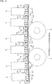
- Fig. 2 is a vertical sectional view of the image recording unit 20 and the support unit 30.
- Fig. 3 is a plan view of the image recording unit 20.
- Fig. 4 is a schematic front view of a base plate 31, the ink ejection heads 21, and fans 24.
- Fig. 5 is a perspective view of the base plate 31 and the ink ejection heads 21.
- Fig. 6 is a view showing the lower surfaces 212 of the ink ejection heads 21 and a lower surface 31b of the base plate 31.
- the ink ejection heads 21 are disposed over the transport path TR.
- the ink ejection heads 21 have the respective lower surfaces 212.
- the lower surfaces 212 of the ink ejection heads 21 are opposed to the transport path TR.
- the lower surfaces 212 of the ink ejection heads 21 each have a plurality of ink ejection ports 211 open toward the transport path TR and for ejecting ink droplets.
- the ink ejection ports 211 are arranged regularly in the width direction.
- the ink ejection heads 21 are fixed to the base plates 31, with lower end portions of the respective ink ejection heads 21 fitted in the mounting holes 311 provided in the base plates 31.
- the lower surfaces 212 of the ink ejection heads 21 are flat surfaces each provided with the plurality of ink ejection ports 211.
- the lower surfaces 212 are disposed substantially parallel to the recording surface 9a of the base material 9.
- the transport rollers 12 immediately under the image recording unit 20 are disposed in the form of an arch that is convex upward.
- the base material 9 immediately under the image recording unit 20 is transported while being curved in an upwardly convex shape (convex toward the recording surface 9a). That is, the transport path TR immediately under the image recording unit 20 is curved in an upwardly convex shape.
- the base plates 31 are arranged along the curved shape of the transport path TR. This causes the ink ejection heads 21 to be arranged in the form of an arch along the transport path TR.
- the base plate 31 is a plate-like member having a rectangular shape as seen in plan view.
- the base plate 31 has three mounting holes 311 penetrating therethrough in the thickness direction.
- the mounting holes 311 are open in a rectangular shape extending in the width direction in an upper surface 31a and the lower surface 31b (opposite surface) of the base plate 31.
- Two of the three mounting holes 311 are positioned upstream, and the remaining one is positioned downstream.
- the two upstream mounting holes 311 are spaced apart in the width direction, and the one downstream mounting hole 311 is disposed in the middle of the two upstream mounting holes 311 as seen in the width direction.
- the three mounting holes 311 are disposed so that the opposite end portions of the one downstream mounting hole 311 as seen in the width direction overlap the two upstream mounting holes 311 as seen in the transport direction.
- the lower end portions of the ink ejection heads 21 having a rectangular shape as seen in plan view are inserted in the three respective mounting holes 311 and fixed therein with fixtures such as screws.
- the width of the mounting holes 311 as seen in the transport direction is greater than the width of the ink ejection heads 21 as seen in the transport direction.
- a sealing material 313 is mounted in the through hole upstream of each of the ink ejection heads 21.
- the sealing material 313 is an elongated member extending in the width direction, and closes a gap between the upstream inner surface of a corresponding one of the mounting holes 311 and the upstream outer surface of each of the ink ejection heads 21. This suppresses the ejection of air from the upstream through hole to thereby suppress irregularities in trajectory of ink droplets ejected from each of the ink ejection heads 21.
- the upstream and downstream inner surfaces of the mounting holes 311 have inward protrusions in intermediate portions of the depth of the mounting holes 311, so that the width of the mounting holes 311 is smaller as seen in the transport direction in the intermediate portions.
- the sealing materials 313 are locked at the upper surfaces of the inward protrusions in the respective mounting holes 311. This restrains the sealing materials 313 from falling downwardly through the base plates 31.
- the through holes downstream of the ink ejection heads 21 are air flow holes 315.
- the air flow holes 315 have respective air outlets 317 open in the lower surface 31b (with reference to Fig. 6 ).
- the air outlets 317 eject air toward the base material 9 transported along the transport path.
- the air flow holes 315 form an air flow path directed from above the base plates 31 toward the air outlets 317.
- the image recording unit 20 includes the plurality of fans 24.
- the fans 24 are disposed, two above each of the base plates 31.
- the two fans 24 are disposed, one on one side and one on the other side of each of the base plates 31 as seen in the width direction.
- Each of the fans 24 blows air downwardly and inwardly as seen in the width direction.
- air from the fans 24 is supplied to the outer surfaces of the three ink ejection heads 21 mounted to the base plate 31.
- the air supplied from the fans 24 flows to the air flow holes 315 and is ejected from the air outlets 317.
- the plurality of fans 24 is an example of an air supply unit for supplying air directed toward the air outlets 317 to the air flow holes 315.
- Fig. 7 is a vertical sectional view showing surroundings of an air flow hole 315 and an air outlet 317 on an enlarged scale.
- ink mist M generated from ink droplets and the like ejected from the ink ejection ports 211 is moved downstream by the movement of the base material 9 while floating between the base material 9 and the lower surface 212 of the corresponding ink ejection head 21.
- the ejection of air from the air outlet 317 in this state allows the ink mist M floating over the base material 9 to adhere to the base material 9. This reduces the adhesion of the ink mist M to the lower surface 31b of the base plate 31 and the like.
- the ink mist M is in very minute amounts as compared with the ink droplets ejected from the ink ejection ports 211 for image formation. For this reason, if the ink mist M adheres to the base material 9, the reduction in printing quality is small. Also, the adhesion of the ink mist M to the lower surface 31b of the base plate 31 or other locations is reduced. This reduces the frequency of cleaning by a user.
- the air flow hole 315 is formed by the inner surface of the mounting hole 311 and the outer surface of the ink ejection head 21.
- the air outlet 317 is provided in a position immediately adjacent to a downstream portion of the ink ejection head 21. This reduces the ink mist M adhering to the base plate 31 supporting the ink ejection head 21 after being generated in the ink ejection ports 211 of the ink ejection head 21.
- a distance d1 between the lower surface 31b of the base plate 31 and the base material 9 is greater than a distance d2 between the lower surface 212 of the ink ejection head 21 and the base material 9.
- the lower surface 31b of the base plate 31 is positioned downstream of the air outlet 317, and the lower surface 212 of the ink ejection head 21 is positioned upstream of the air outlet 317.
- the pressure loss in the gap space between the lower surface 31b of the base plate 31 and the base material 9 in a location downstream of the air outlet 317 is less than the pressure loss in the gap space between the lower surface 212 of the ink ejection head 21 and the base material 9 in a location upstream of the air outlet 317.
- an air flow directed downstream of the air outlet 317 is easily formed by making the distance d1 downstream of the air outlet 317 greater than the distance d2 upstream of the air outlet 317. If air from the air outlet 317 is not guided downstream, a downstream air flow created over the base material 9 by the transport of the base material 9 and a downflow from the air outlet 317 mix with each other, which in turn can cause a turbulent flow. If such a turbulent flow is created, there is a likelihood that the floating ink mist M is swirled up to adhere to the base plate 31 or to the lower surface 212 of the ink ejection head 21. For this reason, the formation of the downstream air flow in the air outlet 317 as shown in Fig. 7 reduces the adhesion of the ink mist M to the base plate 31 and the like.
- the amount (flow rate) of air ejected from downstream ones of the air outlets 317 may be made less than the amount of air ejected from upstream ones of the air outlets 317.
- the amount of air ejected from the air outlets 317 may be decreased stepwise in the downstream direction.
- An air-permeable filter member 319 may be provided inside the air flow hole 315, for example, as shown in Fig. 7 for purposes of adjusting the amount of air ejected from the air outlet 317.
- the provision of the filter member 319 imposes a limit on the passage of air through the air flow hole 315 to thereby reduce the amount of air ejected from the air outlet 317.
- the provision of the filter member 319 allows the purification of air ejected from the air outlet 317.
- the amount of air supplied by the fans 24 may be controlled to change the amount of air supplied to the air flow hole 315, thereby adjusting the amount of air ejected from the air outlet 317.
- a sealing material 33 is provided between every pair of base plates 31 adjacent to each other in the transport direction.
- the sealing material 33 extends in the width direction, and closes a gap between adjacent ones of the base plates 31.
- the sealing materials 33 restrain the air supplied from the fans 24 from passing through the gaps between the base plates 31. This suppresses irregularities in air flow over the base material 9 between the base plates 31, and also allows a greater amount of air to be ejected from the air outlets 317.
- the lower surfaces of the sealing materials 33 are flush with (level with) the lower surfaces 31b of the base plates 31 positioned upstream and downstream thereof. This suppresses the creation of a turbulent flow and the like between the base plates 31 to thereby reduce the adhesion of the ink mist M to the base plates 31.
- the air outlets 317 extend in the width direction, and the length of the air outlets 317 as measured in the width direction is approximately equal to the length of the lower surfaces 212 of the ink ejection heads 21 as measured in the width direction.
- the air outlet 317 extends more outwardly in the width direction than the outermost ink ejection ports 211, 211 as seen in the width direction among the ink ejection ports 211 provided in the ink ejection head 21 adjacent to upstream of the air outlet 317.
- the downflow from the air outlets 317 allows the ink mist M to adhere to the base material 9. This reduces the adhesion of the ink mist M to the lower surface 31b of a base plate 31 on which the ink ejection heads 21 are provided or to the lower surface 31b of a base plate 31 positioned more downstream.
- the air outlets 317 are provided in positions downstream of and immediately adjacent to all of the ink ejection ports 211 provided in the ink ejection heads 21. This effectively reduces the adhesion of the ink mist M to the lower surfaces 31b of the base plates 31 on which the ink ejection heads 21 are provided.
- the image recording unit 20 includes a light irradiator 26 and a suction port 28.
- the light irradiator 26 includes a light source such as an LED, and irradiates the recording surface 9a of the base material 9 with light from the light source.
- the light irradiator 26 is disposed downstream of the most downstream one of the ink ejection heads 21, and semi-cures the inks ejected onto the base material 9.
- the suction port 28 has a slit-shaped suction opening opposed to the recording surface 9a of the base material 9 to suck in air through the suction opening.
- the suction port 28 sucks in air in a location downstream of the four base plates 31, whereby an air flow directed downstream is easily formed between each of the base plates 31 and the base material 9. This allows the ink mist M created in the ink ejection ports 211 to move downstream.
- the suction port 28 may be provided in a position close to the direction switching roller 121 and the like. It is not essential to provide the suction port 28 in a location downstream of the light irradiator 26. The suction port 28 may be provided upstream of the light irradiator 26.
- the lower surfaces 3 1b of the base plates 31 have no suction openings for sucking an atmosphere present over the base material 9.
- the air flow holes 315 and the air outlets 317 are provided in the base plates 31 in the present preferred embodiment to form a downflow in positions close to the ink ejection ports 211. Therefore, the adhesion of the ink mist M is reduced while an increase in size of the printer is prevented.
- Fig. 8 is a view showing the lower surfaces 212 of the ink ejection heads 21 and the lower surface 31b of the base plate 31 according to the second preferred embodiment of the present invention.
- the base plate 31 according to the present preferred embodiment includes air flow holes 321 positioned in downstream spaced apart relation to the respective mounting holes 311. Like the air flow holes 315, the air flow holes 321 are through holes penetrating through the base plate 31 in the thickness direction, and have respective air outlets 323 open in the lower surface 31b (opposite surface) of the base plate 31.
- the air outlets 323 are slit-shaped openings extending in the width direction, and are positioned so as to overlap all of the ink ejection ports 211 of the ink ejection heads 21 upstream adjacent thereto as seen in the transport direction. Gaps formed upstream and downstream of the ink ejection heads 21 inside the mounting holes 311 are closed by the respective sealing materials 313.
- the ejection of air from the air outlet 323 toward the base material 9 allows the ink mist M generated in the ink ejection ports 211 to adhere to the base material 9. This reduces the adhesion of the ink mist M to the base plate 31.
- the distance between the lower surface 31b of the base plate 31 and the base material 9 in a location downstream of the air flow holes 321 is greater than the distance between the lower surface 31b of the base plate 31 and the base material 9 in a location upstream of the air flow holes 321 when the base plate 31 of the present preferred embodiment is opposed to the transport path TR. This allows an air flow directed downstream from the air outlets 317 to be easily formed.
- gaps formed downstream of the ink ejection heads 21 inside the mounting holes 311 may be used as the air flow holes 315, as in the first preferred embodiment.
- Fig. 9 is a vertical sectional view showing surroundings of an air flow hole 315a and an air outlet 317a on an enlarged scale according to a third preferred embodiment of the present invention. Components identical with those described in Fig. 7 are designated by the same reference numerals and characters, and will not be described.
- the air flow hole 315a shown in Fig. 9 is a slit-shaped hole short in length in the transport direction and elongated in the width direction.
- a gap d3 in the air flow hole 315a in the transport direction is less than the distance d1 between the lower surface 31b of the base plate 31 and the base material 9 in a location downstream of the air outlet 317a.
- the pressure loss in the interior space of the air flow hole 315a is less than the pressure loss in the gap space between the lower surface 212 of the ink ejection head 21 and the base material 9 in a location downstream of the air outlet 317a.
- This downflow is ejected from the air outlet 317a toward the base material 9.
- the air outlets 317, 317a, and 323 in the aforementioned preferred embodiments are slit-shaped openings extending in the width direction.
- the air outlets may be a plurality of outlets disposed at a predetermined spacing in the width direction, for example,
- the air supply unit that forcedly supplies air to the air flow holes 315, such as the fans 24, is not essential.
- the base material transport mechanism 10 moves the base material 9 downstream while holding the base material 9 close to the lower surfaces 31b of the base plates 31, whereby an air flow directed downstream is generated over the base material 9.
- the generation of the air flow over the base material 9 causes the atmosphere in the air flow holes 315 to be discharged from the air outlets 317, whereby a downflow is formed.
- the downflow generated as the base material 9 moves may be used for the adhesion of the ink mist M to the base material 9.
Landscapes
- Ink Jet (AREA)
Applications Claiming Priority (1)
| Application Number | Priority Date | Filing Date | Title |
|---|---|---|---|
| JP2019204494A JP7324123B2 (ja) | 2019-11-12 | 2019-11-12 | インクジェット印刷装置およびインクジェット印刷方法 |
Publications (2)
| Publication Number | Publication Date |
|---|---|
| EP3822084A1 true EP3822084A1 (de) | 2021-05-19 |
| EP3822084B1 EP3822084B1 (de) | 2023-08-23 |
Family
ID=73288440
Family Applications (1)
| Application Number | Title | Priority Date | Filing Date |
|---|---|---|---|
| EP20206661.9A Active EP3822084B1 (de) | 2019-11-12 | 2020-11-10 | Tintenstrahldrucker |
Country Status (3)
| Country | Link |
|---|---|
| US (1) | US11673395B2 (de) |
| EP (1) | EP3822084B1 (de) |
| JP (1) | JP7324123B2 (de) |
Families Citing this family (2)
| Publication number | Priority date | Publication date | Assignee | Title |
|---|---|---|---|---|
| JP2023069884A (ja) * | 2021-11-08 | 2023-05-18 | 株式会社Screenホールディングス | インク吐出ヘッドおよびインクジェット印刷装置 |
| JP2024049017A (ja) * | 2022-09-28 | 2024-04-09 | 株式会社リコー | 液体吐出装置 |
Citations (8)
| Publication number | Priority date | Publication date | Assignee | Title |
|---|---|---|---|---|
| US20120281041A1 (en) * | 2010-01-25 | 2012-11-08 | Leoni Napoleon J | Hard imaging devices and hard imaging device operational methods |
| US20150165771A1 (en) * | 2013-12-13 | 2015-06-18 | SCREEN Holdings Co., Ltd. | Inkjet apparatus and method of collecting mist |
| JP2015134496A (ja) | 2013-12-17 | 2015-07-27 | キヤノン株式会社 | インクミスト回収装置、インクジェット記録装置、およびインクミスト回収方法 |
| US20150273835A1 (en) * | 2014-03-25 | 2015-10-01 | Canon Kabushiki Kaisha | Liquid ejection apparatus and liquid ejection method |
| US20160107455A1 (en) * | 2008-10-24 | 2016-04-21 | Miyakoshi Printing Machinery Co., Ltd. | Ink jet recording apparatus |
| US20160214383A1 (en) * | 2015-01-26 | 2016-07-28 | Seiko Epson Corporation | Head unit and recording apparatus |
| JP2016137672A (ja) * | 2015-01-29 | 2016-08-04 | 理想科学工業株式会社 | インクジェット印刷装置 |
| US20190173010A1 (en) * | 2017-12-06 | 2019-06-06 | Samsung Display Co., Ltd. | Inkjet printing apparatus and printing method using the same |
Family Cites Families (6)
| Publication number | Priority date | Publication date | Assignee | Title |
|---|---|---|---|---|
| JP4551357B2 (ja) * | 2006-05-15 | 2010-09-29 | ブラザー工業株式会社 | インクジェット記録装置 |
| JP5371878B2 (ja) * | 2010-05-06 | 2013-12-18 | キヤノン株式会社 | 記録装置 |
| JP2012051127A (ja) * | 2010-08-31 | 2012-03-15 | Riso Kagaku Corp | インクジェット印刷装置 |
| JP2017136695A (ja) * | 2016-02-01 | 2017-08-10 | キヤノン株式会社 | ミスト回収装置および液体吐出装置 |
| JP6705193B2 (ja) * | 2016-02-08 | 2020-06-03 | 富士ゼロックス株式会社 | 液滴吐出装置 |
| JP2018158545A (ja) * | 2017-03-23 | 2018-10-11 | 富士ゼロックス株式会社 | 液滴吐出装置 |
-
2019
- 2019-11-12 JP JP2019204494A patent/JP7324123B2/ja active Active
-
2020
- 2020-11-10 US US17/093,688 patent/US11673395B2/en active Active
- 2020-11-10 EP EP20206661.9A patent/EP3822084B1/de active Active
Patent Citations (8)
| Publication number | Priority date | Publication date | Assignee | Title |
|---|---|---|---|---|
| US20160107455A1 (en) * | 2008-10-24 | 2016-04-21 | Miyakoshi Printing Machinery Co., Ltd. | Ink jet recording apparatus |
| US20120281041A1 (en) * | 2010-01-25 | 2012-11-08 | Leoni Napoleon J | Hard imaging devices and hard imaging device operational methods |
| US20150165771A1 (en) * | 2013-12-13 | 2015-06-18 | SCREEN Holdings Co., Ltd. | Inkjet apparatus and method of collecting mist |
| JP2015134496A (ja) | 2013-12-17 | 2015-07-27 | キヤノン株式会社 | インクミスト回収装置、インクジェット記録装置、およびインクミスト回収方法 |
| US20150273835A1 (en) * | 2014-03-25 | 2015-10-01 | Canon Kabushiki Kaisha | Liquid ejection apparatus and liquid ejection method |
| US20160214383A1 (en) * | 2015-01-26 | 2016-07-28 | Seiko Epson Corporation | Head unit and recording apparatus |
| JP2016137672A (ja) * | 2015-01-29 | 2016-08-04 | 理想科学工業株式会社 | インクジェット印刷装置 |
| US20190173010A1 (en) * | 2017-12-06 | 2019-06-06 | Samsung Display Co., Ltd. | Inkjet printing apparatus and printing method using the same |
Also Published As
| Publication number | Publication date |
|---|---|
| JP7324123B2 (ja) | 2023-08-09 |
| US11673395B2 (en) | 2023-06-13 |
| EP3822084B1 (de) | 2023-08-23 |
| JP2021074998A (ja) | 2021-05-20 |
| US20210138791A1 (en) | 2021-05-13 |
Similar Documents
| Publication | Publication Date | Title |
|---|---|---|
| KR101541802B1 (ko) | 잉크젯 프린터 | |
| EP3822084A1 (de) | Tintenstrahldrucker und tintenstrahldruckverfahren | |
| JP5957967B2 (ja) | 液体吐出装置 | |
| JP2007076175A (ja) | 画像記録装置 | |
| EP2883702B1 (de) | Tintenstrahlvorrichtung und Verfahren zum Sammeln von Nebel | |
| JP6602627B2 (ja) | インクジェット印刷装置およびインクジェット印刷方法 | |
| WO2015087862A1 (ja) | インクジェット記録装置 | |
| US20120113179A1 (en) | Recording apparatus | |
| JP2017132192A (ja) | インクジェット記録装置及びインクジェット記録方法 | |
| JP2015003489A (ja) | シート材搬送装置及びこれを備えた画像形成装置 | |
| JP2005212323A (ja) | 記録装置 | |
| JP7237752B2 (ja) | インクジェット印刷装置およびインクジェット印刷方法 | |
| JP2011218712A (ja) | インクジェット印刷装置 | |
| WO2023080096A1 (ja) | インク吐出ヘッドおよびインクジェット印刷装置 | |
| JP6330386B2 (ja) | 液体吐出装置 | |
| JP5593281B2 (ja) | インクジェット記録装置 | |
| EP3798008B1 (de) | Tintenstrahldruckvorrichtung und tintenstrahldruckverfahren | |
| JP5644140B2 (ja) | インクジェット記録装置 | |
| JP2006240185A (ja) | 画像記録装置 | |
| JP2011218711A (ja) | インクジェット印刷装置 | |
| JP2004025655A (ja) | 画像形成装置 | |
| JP2016198892A (ja) | 印刷装置 | |
| JP2021070177A (ja) | インクジェット印刷装置 | |
| JP2020157581A (ja) | インクジェット印刷装置 | |
| JP2013022898A (ja) | 液体吐出装置、及び、液体吐出方法 |
Legal Events
| Date | Code | Title | Description |
|---|---|---|---|
| PUAI | Public reference made under article 153(3) epc to a published international application that has entered the european phase |
Free format text: ORIGINAL CODE: 0009012 |
|
| STAA | Information on the status of an ep patent application or granted ep patent |
Free format text: STATUS: THE APPLICATION HAS BEEN PUBLISHED |
|
| AK | Designated contracting states |
Kind code of ref document: A1 Designated state(s): AL AT BE BG CH CY CZ DE DK EE ES FI FR GB GR HR HU IE IS IT LI LT LU LV MC MK MT NL NO PL PT RO RS SE SI SK SM TR |
|
| STAA | Information on the status of an ep patent application or granted ep patent |
Free format text: STATUS: REQUEST FOR EXAMINATION WAS MADE |
|
| 17P | Request for examination filed |
Effective date: 20211119 |
|
| RBV | Designated contracting states (corrected) |
Designated state(s): AL AT BE BG CH CY CZ DE DK EE ES FI FR GB GR HR HU IE IS IT LI LT LU LV MC MK MT NL NO PL PT RO RS SE SI SK SM TR |
|
| REG | Reference to a national code |
Ref document number: 602020016153 Country of ref document: DE Ref country code: DE Ref legal event code: R079 Free format text: PREVIOUS MAIN CLASS: B41J0002170000 Ipc: B41J0029377000 |
|
| GRAP | Despatch of communication of intention to grant a patent |
Free format text: ORIGINAL CODE: EPIDOSNIGR1 |
|
| RIC1 | Information provided on ipc code assigned before grant |
Ipc: B41J 2/17 20060101ALI20230131BHEP Ipc: B41J 29/377 20060101AFI20230131BHEP |
|
| STAA | Information on the status of an ep patent application or granted ep patent |
Free format text: STATUS: GRANT OF PATENT IS INTENDED |
|
| INTG | Intention to grant announced |
Effective date: 20230309 |
|
| GRAS | Grant fee paid |
Free format text: ORIGINAL CODE: EPIDOSNIGR3 |
|
| GRAA | (expected) grant |
Free format text: ORIGINAL CODE: 0009210 |
|
| STAA | Information on the status of an ep patent application or granted ep patent |
Free format text: STATUS: THE PATENT HAS BEEN GRANTED |
|
| P01 | Opt-out of the competence of the unified patent court (upc) registered |
Effective date: 20230629 |
|
| AK | Designated contracting states |
Kind code of ref document: B1 Designated state(s): AL AT BE BG CH CY CZ DE DK EE ES FI FR GB GR HR HU IE IS IT LI LT LU LV MC MK MT NL NO PL PT RO RS SE SI SK SM TR |
|
| REG | Reference to a national code |
Ref country code: GB Ref legal event code: FG4D |
|
| REG | Reference to a national code |
Ref country code: CH Ref legal event code: EP |
|
| REG | Reference to a national code |
Ref country code: IE Ref legal event code: FG4D |
|
| REG | Reference to a national code |
Ref country code: DE Ref legal event code: R096 Ref document number: 602020016153 Country of ref document: DE |
|
| REG | Reference to a national code |
Ref country code: LT Ref legal event code: MG9D |
|
| REG | Reference to a national code |
Ref country code: NL Ref legal event code: MP Effective date: 20230823 |
|
| REG | Reference to a national code |
Ref country code: AT Ref legal event code: MK05 Ref document number: 1602149 Country of ref document: AT Kind code of ref document: T Effective date: 20230823 |
|
| PG25 | Lapsed in a contracting state [announced via postgrant information from national office to epo] |
Ref country code: GR Free format text: LAPSE BECAUSE OF FAILURE TO SUBMIT A TRANSLATION OF THE DESCRIPTION OR TO PAY THE FEE WITHIN THE PRESCRIBED TIME-LIMIT Effective date: 20231124 |
|
| PG25 | Lapsed in a contracting state [announced via postgrant information from national office to epo] |
Ref country code: IS Free format text: LAPSE BECAUSE OF FAILURE TO SUBMIT A TRANSLATION OF THE DESCRIPTION OR TO PAY THE FEE WITHIN THE PRESCRIBED TIME-LIMIT Effective date: 20231223 |
|
| PG25 | Lapsed in a contracting state [announced via postgrant information from national office to epo] |
Ref country code: SE Free format text: LAPSE BECAUSE OF FAILURE TO SUBMIT A TRANSLATION OF THE DESCRIPTION OR TO PAY THE FEE WITHIN THE PRESCRIBED TIME-LIMIT Effective date: 20230823 Ref country code: RS Free format text: LAPSE BECAUSE OF FAILURE TO SUBMIT A TRANSLATION OF THE DESCRIPTION OR TO PAY THE FEE WITHIN THE PRESCRIBED TIME-LIMIT Effective date: 20230823 Ref country code: PT Free format text: LAPSE BECAUSE OF FAILURE TO SUBMIT A TRANSLATION OF THE DESCRIPTION OR TO PAY THE FEE WITHIN THE PRESCRIBED TIME-LIMIT Effective date: 20231226 Ref country code: NO Free format text: LAPSE BECAUSE OF FAILURE TO SUBMIT A TRANSLATION OF THE DESCRIPTION OR TO PAY THE FEE WITHIN THE PRESCRIBED TIME-LIMIT Effective date: 20231123 Ref country code: NL Free format text: LAPSE BECAUSE OF FAILURE TO SUBMIT A TRANSLATION OF THE DESCRIPTION OR TO PAY THE FEE WITHIN THE PRESCRIBED TIME-LIMIT Effective date: 20230823 Ref country code: LV Free format text: LAPSE BECAUSE OF FAILURE TO SUBMIT A TRANSLATION OF THE DESCRIPTION OR TO PAY THE FEE WITHIN THE PRESCRIBED TIME-LIMIT Effective date: 20230823 Ref country code: LT Free format text: LAPSE BECAUSE OF FAILURE TO SUBMIT A TRANSLATION OF THE DESCRIPTION OR TO PAY THE FEE WITHIN THE PRESCRIBED TIME-LIMIT Effective date: 20230823 Ref country code: IS Free format text: LAPSE BECAUSE OF FAILURE TO SUBMIT A TRANSLATION OF THE DESCRIPTION OR TO PAY THE FEE WITHIN THE PRESCRIBED TIME-LIMIT Effective date: 20231223 Ref country code: HR Free format text: LAPSE BECAUSE OF FAILURE TO SUBMIT A TRANSLATION OF THE DESCRIPTION OR TO PAY THE FEE WITHIN THE PRESCRIBED TIME-LIMIT Effective date: 20230823 Ref country code: GR Free format text: LAPSE BECAUSE OF FAILURE TO SUBMIT A TRANSLATION OF THE DESCRIPTION OR TO PAY THE FEE WITHIN THE PRESCRIBED TIME-LIMIT Effective date: 20231124 Ref country code: FI Free format text: LAPSE BECAUSE OF FAILURE TO SUBMIT A TRANSLATION OF THE DESCRIPTION OR TO PAY THE FEE WITHIN THE PRESCRIBED TIME-LIMIT Effective date: 20230823 Ref country code: AT Free format text: LAPSE BECAUSE OF FAILURE TO SUBMIT A TRANSLATION OF THE DESCRIPTION OR TO PAY THE FEE WITHIN THE PRESCRIBED TIME-LIMIT Effective date: 20230823 |
|
| PGFP | Annual fee paid to national office [announced via postgrant information from national office to epo] |
Ref country code: FR Payment date: 20231121 Year of fee payment: 4 Ref country code: DE Payment date: 20231128 Year of fee payment: 4 |
|
| PG25 | Lapsed in a contracting state [announced via postgrant information from national office to epo] |
Ref country code: PL Free format text: LAPSE BECAUSE OF FAILURE TO SUBMIT A TRANSLATION OF THE DESCRIPTION OR TO PAY THE FEE WITHIN THE PRESCRIBED TIME-LIMIT Effective date: 20230823 |
|
| PG25 | Lapsed in a contracting state [announced via postgrant information from national office to epo] |
Ref country code: ES Free format text: LAPSE BECAUSE OF FAILURE TO SUBMIT A TRANSLATION OF THE DESCRIPTION OR TO PAY THE FEE WITHIN THE PRESCRIBED TIME-LIMIT Effective date: 20230823 |
|
| PG25 | Lapsed in a contracting state [announced via postgrant information from national office to epo] |
Ref country code: SM Free format text: LAPSE BECAUSE OF FAILURE TO SUBMIT A TRANSLATION OF THE DESCRIPTION OR TO PAY THE FEE WITHIN THE PRESCRIBED TIME-LIMIT Effective date: 20230823 Ref country code: RO Free format text: LAPSE BECAUSE OF FAILURE TO SUBMIT A TRANSLATION OF THE DESCRIPTION OR TO PAY THE FEE WITHIN THE PRESCRIBED TIME-LIMIT Effective date: 20230823 Ref country code: ES Free format text: LAPSE BECAUSE OF FAILURE TO SUBMIT A TRANSLATION OF THE DESCRIPTION OR TO PAY THE FEE WITHIN THE PRESCRIBED TIME-LIMIT Effective date: 20230823 Ref country code: EE Free format text: LAPSE BECAUSE OF FAILURE TO SUBMIT A TRANSLATION OF THE DESCRIPTION OR TO PAY THE FEE WITHIN THE PRESCRIBED TIME-LIMIT Effective date: 20230823 Ref country code: DK Free format text: LAPSE BECAUSE OF FAILURE TO SUBMIT A TRANSLATION OF THE DESCRIPTION OR TO PAY THE FEE WITHIN THE PRESCRIBED TIME-LIMIT Effective date: 20230823 Ref country code: CZ Free format text: LAPSE BECAUSE OF FAILURE TO SUBMIT A TRANSLATION OF THE DESCRIPTION OR TO PAY THE FEE WITHIN THE PRESCRIBED TIME-LIMIT Effective date: 20230823 Ref country code: SK Free format text: LAPSE BECAUSE OF FAILURE TO SUBMIT A TRANSLATION OF THE DESCRIPTION OR TO PAY THE FEE WITHIN THE PRESCRIBED TIME-LIMIT Effective date: 20230823 |