EP3812601A1 - Formteil, verstellsicherung mit dem formteil, landwirtschaftliche arbeitsmaschine mit der verstellsicherung und verfahren zum montieren der verstellsicherung - Google Patents
Formteil, verstellsicherung mit dem formteil, landwirtschaftliche arbeitsmaschine mit der verstellsicherung und verfahren zum montieren der verstellsicherung Download PDFInfo
- Publication number
- EP3812601A1 EP3812601A1 EP20203002.9A EP20203002A EP3812601A1 EP 3812601 A1 EP3812601 A1 EP 3812601A1 EP 20203002 A EP20203002 A EP 20203002A EP 3812601 A1 EP3812601 A1 EP 3812601A1
- Authority
- EP
- European Patent Office
- Prior art keywords
- bolt
- molded part
- lug
- securing
- frame component
- Prior art date
- Legal status (The legal status is an assumption and is not a legal conclusion. Google has not performed a legal analysis and makes no representation as to the accuracy of the status listed.)
- Granted
Links
Images



Classifications
-
- F—MECHANICAL ENGINEERING; LIGHTING; HEATING; WEAPONS; BLASTING
- F16—ENGINEERING ELEMENTS AND UNITS; GENERAL MEASURES FOR PRODUCING AND MAINTAINING EFFECTIVE FUNCTIONING OF MACHINES OR INSTALLATIONS; THERMAL INSULATION IN GENERAL
- F16B—DEVICES FOR FASTENING OR SECURING CONSTRUCTIONAL ELEMENTS OR MACHINE PARTS TOGETHER, e.g. NAILS, BOLTS, CIRCLIPS, CLAMPS, CLIPS OR WEDGES; JOINTS OR JOINTING
- F16B43/00—Washers or equivalent devices; Other devices for supporting bolt-heads or nuts
- F16B43/02—Washers or equivalent devices; Other devices for supporting bolt-heads or nuts with special provisions for engaging surfaces which are not perpendicular to a bolt axis or do not surround the bolt
-
- F—MECHANICAL ENGINEERING; LIGHTING; HEATING; WEAPONS; BLASTING
- F16—ENGINEERING ELEMENTS AND UNITS; GENERAL MEASURES FOR PRODUCING AND MAINTAINING EFFECTIVE FUNCTIONING OF MACHINES OR INSTALLATIONS; THERMAL INSULATION IN GENERAL
- F16B—DEVICES FOR FASTENING OR SECURING CONSTRUCTIONAL ELEMENTS OR MACHINE PARTS TOGETHER, e.g. NAILS, BOLTS, CIRCLIPS, CLAMPS, CLIPS OR WEDGES; JOINTS OR JOINTING
- F16B21/00—Means for preventing relative axial movement of a pin, spigot, shaft or the like and a member surrounding it; Stud-and-socket releasable fastenings
- F16B21/10—Means for preventing relative axial movement of a pin, spigot, shaft or the like and a member surrounding it; Stud-and-socket releasable fastenings by separate parts
- F16B21/12—Means for preventing relative axial movement of a pin, spigot, shaft or the like and a member surrounding it; Stud-and-socket releasable fastenings by separate parts with locking-pins or split-pins thrust into holes
- F16B21/14—Details of locking-pins or split-pins
-
- F—MECHANICAL ENGINEERING; LIGHTING; HEATING; WEAPONS; BLASTING
- F16—ENGINEERING ELEMENTS AND UNITS; GENERAL MEASURES FOR PRODUCING AND MAINTAINING EFFECTIVE FUNCTIONING OF MACHINES OR INSTALLATIONS; THERMAL INSULATION IN GENERAL
- F16C—SHAFTS; FLEXIBLE SHAFTS; ELEMENTS OR CRANKSHAFT MECHANISMS; ROTARY BODIES OTHER THAN GEARING ELEMENTS; BEARINGS
- F16C11/00—Pivots; Pivotal connections
- F16C11/02—Trunnions; Crank-pins
-
- F—MECHANICAL ENGINEERING; LIGHTING; HEATING; WEAPONS; BLASTING
- F16—ENGINEERING ELEMENTS AND UNITS; GENERAL MEASURES FOR PRODUCING AND MAINTAINING EFFECTIVE FUNCTIONING OF MACHINES OR INSTALLATIONS; THERMAL INSULATION IN GENERAL
- F16C—SHAFTS; FLEXIBLE SHAFTS; ELEMENTS OR CRANKSHAFT MECHANISMS; ROTARY BODIES OTHER THAN GEARING ELEMENTS; BEARINGS
- F16C11/00—Pivots; Pivotal connections
- F16C11/04—Pivotal connections
- F16C11/045—Pivotal connections with at least a pair of arms pivoting relatively to at least one other arm, all arms being mounted on one pin
-
- F—MECHANICAL ENGINEERING; LIGHTING; HEATING; WEAPONS; BLASTING
- F16—ENGINEERING ELEMENTS AND UNITS; GENERAL MEASURES FOR PRODUCING AND MAINTAINING EFFECTIVE FUNCTIONING OF MACHINES OR INSTALLATIONS; THERMAL INSULATION IN GENERAL
- F16B—DEVICES FOR FASTENING OR SECURING CONSTRUCTIONAL ELEMENTS OR MACHINE PARTS TOGETHER, e.g. NAILS, BOLTS, CIRCLIPS, CLAMPS, CLIPS OR WEDGES; JOINTS OR JOINTING
- F16B19/00—Bolts without screw-thread; Pins, including deformable elements; Rivets
- F16B19/02—Bolts or sleeves for positioning of machine parts, e.g. notched taper pins, fitting pins, sleeves, eccentric positioning rings
-
- F—MECHANICAL ENGINEERING; LIGHTING; HEATING; WEAPONS; BLASTING
- F16—ENGINEERING ELEMENTS AND UNITS; GENERAL MEASURES FOR PRODUCING AND MAINTAINING EFFECTIVE FUNCTIONING OF MACHINES OR INSTALLATIONS; THERMAL INSULATION IN GENERAL
- F16B—DEVICES FOR FASTENING OR SECURING CONSTRUCTIONAL ELEMENTS OR MACHINE PARTS TOGETHER, e.g. NAILS, BOLTS, CIRCLIPS, CLAMPS, CLIPS OR WEDGES; JOINTS OR JOINTING
- F16B39/00—Locking of screws, bolts or nuts
- F16B39/02—Locking of screws, bolts or nuts in which the locking takes place after screwing down
- F16B39/04—Locking of screws, bolts or nuts in which the locking takes place after screwing down with a member penetrating the screw-threaded surface of at least one part, e.g. a pin, a wedge, cotter-pin, screw
-
- F—MECHANICAL ENGINEERING; LIGHTING; HEATING; WEAPONS; BLASTING
- F16—ENGINEERING ELEMENTS AND UNITS; GENERAL MEASURES FOR PRODUCING AND MAINTAINING EFFECTIVE FUNCTIONING OF MACHINES OR INSTALLATIONS; THERMAL INSULATION IN GENERAL
- F16C—SHAFTS; FLEXIBLE SHAFTS; ELEMENTS OR CRANKSHAFT MECHANISMS; ROTARY BODIES OTHER THAN GEARING ELEMENTS; BEARINGS
- F16C2310/00—Agricultural machines
Definitions
- the present invention relates to a molded part for securing a bolt against both rotation and axial displacement, an adjustment lock with such a molded part, an agricultural machine with such an adjustment lock, and a method for assembling the adjustment lock.
- An axial displacement of a bolt penetrating a frame component is prevented, for example, by means of a pin penetrating the bolt.
- the pin serves as a stop and prevents the bolt from moving in a longitudinal direction of the bolt.
- such a securing does not prevent the bolt from rotating in the tangential direction about a longitudinal axis of the bolt.
- the pamphlet DE 100 50 143 A1 discloses a bolt safety device with which a bolt passing through a frame component is secured against axial displacement and / or rotation.
- the bolt securing device comprises a securing element which comprises an elongated hole tapering towards one side. A groove-like recess is provided in the bolt.
- the bolt can be pushed into the elongated hole so that it passes through it, and can then be displaced in the elongated hole so that an edge of the elongated hole engages in the groove-like depression.
- the bolt which penetrates the securing element in this way is secured against axial displacement and / or rotation by screwing the securing element to the frame component.
- the object of the present invention is to create an alternative adjustment lock for a bolt, in particular an agricultural work machine, which not only prevents the bolt from being displaced in one spatial direction, but also also secures against tangential rotation about its longitudinal axis, which enables the use of already manufactured bolts, and which can be assembled quickly and easily, in particular without tools, and can be manufactured inexpensively.
- a molded part is created for this.
- the molded part is intended to secure a bolt against twisting. It is also intended to secure the bolt against axial displacement.
- a bolt within the meaning of the invention has a cylindrical shape with a circular cross section and extends around a longitudinal axis in and against a longitudinal direction.
- the molded part has a base body in which a bolt receptacle for receiving the bolt is arranged.
- the bolt receptacle preferably has a contour that is adapted to the cross section of the bolt in terms of its shape and its diameter in such a way that the bolt can be inserted into the bolt receptacle in or against the longitudinal direction. The inserted bolt can then be rotated about the longitudinal axis in the bolt receptacle and displaced in and against the longitudinal axis.
- the molded part has a retaining lug which extends from the base body to a free end. With the retaining lug, the bolt can be secured against shifting in or against the longitudinal direction.
- the molded part has a securing lug, which extends from the base body to a free end.
- the bolt can be secured against twisting in and against a tangential direction about the longitudinal axis with the locking lug.
- the molded part therefore enables the bolt to be secured both against axial displacement in or against the longitudinal direction and against rotation in and against the tangential direction about the longitudinal axis of the bolt.
- the retaining lug preferably has a passage for receiving a pin.
- the implementation enables the molded part to be fastened at a defined position of the bolt by means of the pin.
- the pin can serve as a stop and limit displacement of the bolt in or against the longitudinal direction.
- the molded part is made in one piece.
- the molded part is made from a stamped component. It is preferably made from a flat strip material, particularly preferably from an endless flat strip material, for example from a sheet metal. It preferably has a constant thickness. In this embodiment it can be produced particularly inexpensively and quickly. However, it can also have reinforcements, in particular in the area of connections of the retaining lug and / or the securing lug to the base body.
- the molded part is preferably first punched from the flat strip material.
- the securing lug and / or the retaining lug of the punched component stamped from the flat strip material extend in the same plane as the base body.
- the securing lug and / or the retaining lug are then preferably bent out of the stamped component.
- Both the securing lug and the retaining lug are preferably bent out of the base body.
- the securing lug and / or the holding lug of the molded part extends at a substantially right angle to a plane formed by the base body.
- the securing lug and / or the retaining lug can in principle also extend at a different angle to the base body.
- the molded part can also be formed in several pieces, and the securing lug and / or the retaining lug can be fastened to the base body, for example by welding, screwing or similar.
- a one-piece production of the molded part is, in comparison, more stable, less complex and more cost-effective.
- the molded part is designed to be mirror-symmetrical about at least one plane of symmetry.
- the symmetry simplifies the assembly of the molded part.
- the retaining lug and the securing lug can extend in the same spatial plane, in spatial planes parallel to one another or in spatial planes arranged transversely to one another.
- the securing lug and / or the retaining lug are preferably arranged adjacent to the bolt receptacle.
- the securing lug and / or the holding lug of the punched-out stamped component can each extend from the base body into the bolt receptacle.
- the molded part is produced from the base body by bending the securing lug and the retaining lug. As a result, the bolt receptacle of the molded part is enlarged around the securing lug and the retaining lug in a region of the securing nose bent out of the base body and in a region of the holding nose bent out of the base body.
- the dimensions of the bolt receptacle can be dimensioned in such a way that the bolt can only then be pushed into the bolt receptacle.
- the bolt receptacle of this embodiment preferably has a circular cross section, at least in some areas, in particular between the securing lug and the retaining lug.
- the bolt receptacle has the same or only an insignificantly larger diameter than the bolt in the areas with a circular cross section.
- the securing lug and / or the retaining lug are spaced apart from the bolt receptacle.
- the securing lug and / or the retaining lug can also be designed as a bulge or molded-on part of the base body. Furthermore, they can be positioned on an edge, in particular on one end, of the base body. In a preferred embodiment, the securing lug and the retaining lug are arranged at opposite ends of the base body.
- the retaining lug and the securing lug are preferably arranged on opposite sides of the bolt receptacle.
- a distance between the securing lug and the retaining lug is then as large as possible.
- they can be arranged offset to one another in a tangential direction around the bolt receptacle at an angle, in particular at a right angle.
- the molded part has more than one retaining lug and / or more than one securing lug. It is particularly preferred that the molded part has two retaining lugs that are arranged on opposite sides of the bolt receptacle, and / or that it has two securing lugs that are arranged on opposite sides of the bolt receptacle.
- the molded part can be designed to be essentially ring-shaped.
- the base body extends essentially along a plane.
- the securing lug and the retaining lug can be arranged on the same side of the base body or on opposite sides of the base body.
- the molded part is essentially U-shaped.
- the securing lug and / or the retaining lug can form a free leg of the molded part, or can be arranged in or on a leg of the molded part.
- the bolt receptacle is preferably arranged in a strut connecting the legs.
- the securing nose and the retaining nose can also in this embodiment in the tangential direction around the bolt receptacle be arranged offset from one another by an angle. Furthermore, they can be bent out of the strut connecting the legs.
- an adjustment lock which comprises a bolt, such a molded part, a pin and a frame component.
- this adjustment lock additionally has the molded part.
- the bolt is also secured against tangential rotation about the longitudinal axis by means of the molded part.
- the adjustment lock has a shift lock which interacts positively and / or non-positively with the bolt.
- the shift lock comprises a retaining lug that extends from the base body to a free end.
- a bushing is provided in the retaining lug. It also includes a pen.
- the pin penetrates the retaining lug and a through-hole through the bolt. As a result, the bolt is secured against twisting in and against a tangential direction about the longitudinal axis.
- the adjustment lock has an anti-rotation lock.
- the anti-rotation device interacts positively and / or non-positively with a frame component which is provided for mounting the bolt.
- a frame component which is provided for mounting the bolt.
- it has a securing lug that extends from the base body to a free end.
- it has a recess which is arranged on the frame component. In the assembled state, the locking lug engages in the recess.
- the anti-twist device is provided to secure the bolt against twisting in and against a tangential direction about the longitudinal axis.
- the molded part enables the use of conventional components, in particular conventional bolts and pins. Since the adjustment lock only requires the additional molded part compared to the conventional shift lock, it can be retrofitted. When retrofitting, the frame component must be provided with a recess designed to correspond to the securing lug.
- a through hole for receiving the pin is preferably arranged in the bolt. Also preferably, in the assembled state of the adjustment lock, the pin passes through both the through-hole of the bolt and the passage for receiving the pin in the retaining lug of the molded part. As a result, the through-hole enables the molded part to be fastened to the bolt by means of the pin.
- a receptacle for the bolt and a recess for the securing lug are also preferably provided in the frame component.
- the securing lug can particularly preferably be inserted into the recess.
- the recess and the securing lug are designed to correspond to one another, in particular with regard to their shape and dimensions.
- the receptacle provided for the bolt can be arranged in the frame component adjacent to the recess.
- the recess can also be arranged at a distance from the receptacle.
- the adjustment lock provides that the bolt is guided through the receptacle of the frame component so that the through-hole for the pin is arranged on a side of the frame component having the recess, the molded part on the side of the frame component having the recess is pushed onto the bolt, so that the securing lug engages in the recess, and the through-hole is arranged on the side of the molded part facing away from the frame component, the pin being inserted into the passage of the retaining lug and into the through-hole so that it has both the retaining lug as well as the through hole.
- the molded part can no longer be rotated about the longitudinal axis. Since the pin continues to penetrate both the retaining lug and the bolt, the molded part is attached to the bolt. This means that the bolt can no longer be rotated either.
- the molded part acts as a stop for the bolt, so that it can no longer be displaced in or against the longitudinal direction.
- an additional shift lock for example by means of a further adjustment lock or just a further pin, can be provided on a side of the frame component facing away from the adjustment lock.
- a bolt with a widened end acting as a stop can be used.
- the object is also achieved with an agricultural work machine with such an adjustment lock.
- the adjustment lock is preferably used for bolts that are used to store rotatable components. Such components are regularly mounted on the bolt by means of pivot bearings such as ball bearings, roller bearings or roller bearings. If the pivot bearing is stiff, wear can be caused by twisting the bolt.
- the adjustment lock reduces or prevents such wear on the bolt.
- the invention is applicable to any agricultural work machine. It is preferably used in haymaking machines, especially in a tedder or rotary swather.
- the assembly can be carried out very quickly and easily, in particular without tools.
- the adjustment lock can also be removed very quickly and easily by removing the pin.
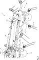
- Fig. 1 shows a detail from an agricultural working machine 7, here a haymaking machine, namely a tedder.
- an agricultural working machine 7, haymaking machine and tedder are used synonymously.
- the tedder 7 has tedders 70 for turning agricultural crops, which are rotatably arranged on a boom 73 about an axis of rotation (not shown).
- the rotary tedders 70 each have a rotary disk 75, on which arms 71 are arranged in a uniformly distributed manner, which extend approximately radially from the axis of rotation.
- the number of arms 71 is six here. However, more or fewer arms 71 can be provided.
- Tines 72 are arranged on the arms 71, with which the crop lying on the ground (not shown) can be lifted and thrown off.
- the gyro plates 75 are provided to be rotatable about an axis (not shown) extending transversely to the ground.
- each of the rotary disc 75 is a wheel (not designated) is attached with which the tedder 70 is guided over the ground.
- the boom 73 comprises a first, externally arranged boom part 731, which carries a tedder 70 and can be pivoted with respect to a second boom part 732, which also carries a tedder 70, by means of a hydraulic cylinder 74.
- the first boom part 731 can be adjusted from an operating position (not designated) into a transport position (not shown) and back. In the transport position, the first boom part 731 is arranged pivoted by an angle (not shown), in particular approximately at right angles, with respect to the second boom part 732.
- a first end 741 of the hydraulic cylinder 74 is attached to the first boom part 731 for this purpose.
- a second end 742 of the hydraulic cylinder 74 is attached to the second boom part 732 of the boom 73 for this purpose.
- Both ends 741, 742 of the hydraulic cylinder 74 are each hinged to their boom part 731, 732 so as to be rotatable.
- two frame components 4 are attached to the boom part 731, 732 at both ends 741, 742, here welded, between which a bolt 3 extends, which is mounted non-rotatably between the frame components 4.
- the bolts 3 each serve as a bearing for a rotary bearing of the hydraulic cylinder 74.
- the bolt 3 at the first end 741 of the hydraulic cylinder 74 is secured in a conventional manner against twisting and displacement with respect to the frame components 4 with which it is attached to the boom.
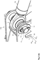
- an adjustment lock 6 (see Fig. Fig. 3 (b) ) intended to secure the bolt against twisting and shifting. Therefore, the second end 742 of the hydraulic cylinder 74 is in the Fig. 3 (a) and (b) shown enlarged.
- the adjustment lock comprises a molded part according to the invention, which is initially based on the Fig. 2 (a) and (b) is described.
- Fig. 2 shows in (a) the molded part 1 according to the invention for the adjustment lock 6.
- Fig. 2 (b) a stamped component 1 'is shown, from which the molded part 1 of Fig. 2 (a) is made.
- the molded part 1 has a base body 15 in which a bolt receptacle 10 for receiving a bolt 3 (see Fig. Fig. 3 ) is arranged.
- the base body 15 extends in a plane E, here transversely to a longitudinal direction 52.
- the plane E is spanned by lines (not designated) along an insertion direction 51 and along an extension direction 53.
- the base body 15 has a greater length I than width b.
- the base body 15 here has a constant thickness d.
- reinforcements can also be provided on the base body 15, so that the base body 15 is made thicker in areas than other areas of the base body 15.
- the bolt receptacle 10 is arranged approximately in the center of the base body 15.
- the molded part 1 is therefore approximately annular.
- the bolt receptacle 10 is designed to correspond to the bolt 3 onto which it is slipped. It is suitable for receiving a cylindrically shaped bolt 3 with a circular cross section (not designated). For this purpose, it is designed to be circular in some areas and has a diameter D A which is slightly larger than the bolt diameter D B. In the areas in which the bolt receptacle 10 is not circular, it has at least the same diameter D A or is made larger.
- the bolt 3 can therefore be inserted into the bolt receptacle 10 in such a way that it penetrates it.
- the bolt 3 inserted into the bolt receptacle 10 extends in its longitudinal direction 52 transversely to the plane E.
- the molded part 1 has a securing lug 11 and a retaining lug 12.
- the securing lug 11 is provided for securing the bolt 3 against displacement here against the longitudinal direction 52.
- the retaining lug 12 is provided for securing the bolt 3 against rotation in and against a tangential direction 50 about the longitudinal axis 52.
- the securing nose 11 is bent out of the base body 15 along a first, linear connection 111, and the retaining nose 12 is bent out along a second, linear connection 121. As a result, the retaining lug 12 and the securing lug 11 extend at an approximately right angle ⁇ to the base body 15.
- the retaining lug 12 here extends from the main body 15 in the longitudinal direction 52, the securing lug 11 here extending from the main body 15 against the longitudinal direction 52.
- the securing lug 11 and the retaining lug 12 are therefore arranged on opposite sides 151, 152 of the base body 15.
- the retaining lug 12 and the securing lug 11 are on opposite sides (not designated) of the bolt receptacle 10 arranged. They are designed with mirror symmetry.
- the molded part 1 is overall mirror-symmetrical with respect to a mirror surface S1 centrally penetrating the retaining lug 12 and the securing lug 11.
- a passage 13 is also arranged in the retaining lug 12.
- the bushing 13 penetrates the retaining lug 12 so that a pin 2 (see Fig. Fig. 2 ) can be pushed into the implementation 13.
- the molded part 1 is made in one piece from a stamped component 1 '(see Fig. Fig. 2 (b) ), which is punched out of a flat strip material.
- the punched component 1 ' has a base body 15', a securing lug 11 'and a retaining lug 12'.
- the securing lug 11 'and the retaining lug 12' of the punched component 1 ' extend in the plane E transversely to the longitudinal axis 52.
- the incisions 14 ′ are shaped such that a contour (not designated) of the securing lug 11 ′ and the retaining lug 12 ′ of the punched component 1 ′ corresponds to a contour (not designated) of the securing lug 11 and the retaining lug 12 of the molded part 1.
- the punched component 1 ′ has a bolt receptacle 10 ′, the contour (not designated) of which in the circular areas corresponds to a contour (not designated) of the bolt receptacle 10 of the molded part 1.
- the securing lug 11 'and the retaining lug 12' are bent along the connections 111, 121 to produce the molded part 1.
- the securing lug 11 ' is bent out of the base body 15' along the first of the two connections 11 and the retaining lug 12 'along the second of the two connections 121 in opposite longitudinal directions 52, so that the retaining lug 12' extends in the longitudinal direction 52 and the Securing lug 11 ′ extends against the longitudinal direction 52.
- the bolt receptacle 10 ' is enlarged by the bent-out securing lug 11' and the bent-out retaining lug 12 '.
- the bolt receptacle 10 is therefore not circular in the area of the securing lug 11 and the retaining lug 12 and is enlarged up to the connection 111 of the securing lug 11 and up to the connection 121 of the retaining lug 12.
- the molded part 1 can be pushed onto the bolt 3 against the longitudinal direction 52. This shows Fig. 3 (a) .
- Fig. 3 shows in (a) and (b) in each case the section A of Fig. 1 .
- An adjustment lock 6 is shown in an exploded view in (a) and in FIG Fig. 3 (b) the mounted adjustment lock 6.
- the adjustment lock 6 has the bolt 3, the molded part 1, a pin 2 and a frame component 4.
- the bolt 3 extends at the second end 742 of the hydraulic cylinder 74 between the frame component 4 and a second frame component 4.
- the frame components 4 are arranged approximately parallel to one another and attached to the extension arm 73.
- the bolt 3 is supported between them. It is used to support a pivot bearing (not shown) of the hydraulic cylinder 74.
- the adjustment lock 6 is intended to reduce or even prevent wear on the bolt 3, which can occur, for example, in the case of a stiff pivot bearing on the bolt 3 and / or a receptacle 40 in the frame component 4 through which the bolt 3 passes. For this purpose, it secures the bolt 3 not only against displacement but also against rotation.
- the frame component 4 of the adjustment lock 6 has the receptacle 40 for the bolt 3 which completely penetrates the frame component 4.
- the frame component 4 has a recess 41 for the securing component 11.
- the recess 41 here directly adjoins the receptacle 40.
- the recess 41 also completely penetrates the frame component 4.
- a recess 41 that does not completely penetrate it is also sufficient.
- the bolt 3 is cylindrical so that it is circular in cross section. It extends from a first end 31 to a second end 32.
- the bolt 3 is inserted in the longitudinal direction 52 through the receptacle 40 of the frame component 4.
- At the first end 31 of the bolt 3 there is a through hole 33 which is provided for receiving the pin 2.
- the pin 2 can be inserted into the through-hole 33 in an insertion direction 51 which extends transversely to the longitudinal direction 52.
- the anti-rotation device 6 is installed by first guiding the bolt 3 in or against the longitudinal direction 52 through the receptacle 40 of the frame component 4, so that a through-hole 33 provided in the bolt 3 is arranged on the side of the frame component 4 having the recess 41.
- the molded part 1 is then pushed onto the bolt 3 against the longitudinal direction 52 until it rests on the frame component 4. In this state, the securing lug 11 of the molded part 1 engages in the recess 41 of the frame component 4.
- the through-hole 33 is arranged in the bolt 3 on the side (151) of the molded part 1 facing away from the frame component 4.
- the bolt 3 can then be rotated in such a way that the through-hole 33 and the passage 13 in the retaining lug 12 of the molded part 1 are aligned with one another.
- the molded part 1 is then fastened in that the pin 2 is passed through the passage 13 in the retaining lug 12 of the molded part 1 and the through-hole 33 in the bolt 3 until it penetrates both.
- Such an adjustment lock 6 can likewise be arranged on the second frame component 4, which is parallel to the frame component 4 of the adjustment lock 6.
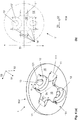
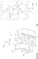
- FIGS 4-6 each show further embodiments of the molded part 1, wherein in (a) the molded part 1 is shown in a perspective view, and in (b) a stamped component 1 'for producing the molded part 1 is shown.
- Fig. 4 Compared to the embodiment of Fig. 2 has the molded part 1 of the Fig. 4 a circular contour.
- the bolt receptacle 10 is arranged in the middle.
- the molded part 1 has Fig. 4 two retaining lugs 12 and two securing lugs 11, which are arranged adjacent to the bolt receptacle 10.
- the securing lugs 11 and the retaining lugs 12 are bent out of the base body 15 so that they extend at an approximately right angle ⁇ to the base body 15. Both the securing lugs 11 and the retaining lugs 12 are arranged on opposite sides of the bolt receptacle 10. A securing lug 11 therefore always alternates with a retaining lug 12.
- the adjacent securing lugs 11 and retaining lugs 12 are each offset from one another by a right angle (not shown) in the tangential direction 101 about the bolt receptacle 10.
- the molded part 1 is therefore designed mirror-symmetrically to a mirror plane bisecting the securing lugs 11 (not shown) and to a mirror plane bisecting the retaining lugs 12 (not shown).
- the retaining lugs 12 and the securing lugs 11 also extend here in opposite longitudinal directions 52.
- molded part 1 of Fig. 5 and 6th In contrast, they are U-shaped. They therefore each have two free legs 161, 162 which are connected to one another by a strut 163.
- the molded parts 1 are made in one piece from a stamped component 1 '.
- the free legs 161, 162 are bent by an essentially right angle ⁇ with respect to the strut 163.
- the bolt receptacle 10 is arranged in the middle of the strut 163 in both embodiments. In the area of the strut 163, the bolt receptacle 10 has a circular cross section. In addition, both embodiments each have two retaining lugs 12, which are arranged adjacent to the bolt receptacle 10 and on opposite sides of the bolt receptacle 10.
- the retaining lugs 12 are each connected to one of the free legs 161, 162. They are therefore adjusted by the right angle ⁇ when the free legs 161, 162 are bent relative to the strut 163. They therefore have the right angle ⁇ with respect to a plane E formed by the strut 163.
- a securing lug 11 is arranged on the edge 17 of the two free legs 161, 162.
- the securing lugs 11 are each arranged in alignment with the retaining lug 12.
- the securing lugs 11 are therefore also adjusted by the right angle ⁇ when the free legs 161, 162 are bent relative to the strut 163. They therefore also have the right angle ⁇ with respect to the plane E formed by the strut 163.
- the embodiment of the Fig. 6 differs from that of the Fig. 5 in that a securing lug 11 is arranged on the edge 17 of each leg 161, 162 at each end.
- This molded part 1 therefore has four securing lugs 11.
- Both embodiments are designed to be mirror-symmetrical with respect to a first mirror plane S1 running centrally between the free legs 161, 162 and a second mirror plane S2 bisecting the retaining lugs 12.
Landscapes
- Engineering & Computer Science (AREA)
- General Engineering & Computer Science (AREA)
- Mechanical Engineering (AREA)
- Mutual Connection Of Rods And Tubes (AREA)
Abstract
Description
- Die vorliegende Erfindung betrifft ein Formteil zum Sichern eines Bolzens sowohl gegen ein Verdrehen als auch gegen ein axiales Verschieben, eine Verstellsicherung mit einem solchen Formteil, eine landwirtschaftliche Arbeitsmaschine mit einer solchen Verstellsicherung sowie ein Verfahren zum Montieren der Verstellsicherung.
- Ein axiales Verschieben eines ein Rahmenbauteil durchsetzenden Bolzens wird beispielsweise mittels eines den Bolzen durchsetzenden Stiftes verhindert. Der Stift dient als Anschlag und verhindert das Verschieben des Bolzens in eine Längsrichtung des Bolzens. Eine solche Sicherung verhindert aber nicht das Verdrehen des Bolzens in tangentialer Richtung um eine Längsachse des Bolzens.
- Um einen Bolzen gegen ein solches Verdrehen zu sichern, wird dieser beispielsweise am Rahmenbauteil angeschweißt.
- Die Druckschrift
DE 100 50 143 A1 offenbart eine Bolzensicherung, mit der ein Bolzen, der ein Rahmenbauteil durchsetzt, gegen ein axiales Verschieben und/oder Verdrehen gesichert wird. Die Bolzensicherung umfasst ein Sicherungselement, das ein sich zu einer Seite hin verjüngendes Langloch umfasst. Im Bolzen ist eine nutartige Vertiefung vorgesehen. Der Bolzen ist in das Langloch einschiebbar, so dass er dieses durchsetzt, und dann im Langloch verschiebbar, so dass eine Kante des Langlochs in die nutartige Vertiefung eingreift. Der das Sicherungselement so durchsetzende Bolzen wird durch Verschrauben des Sicherungselementes am Rahmenbauteil gegen das axiale Verschieben und/oder Verdrehen gesichert. - Aufgabe der vorliegenden Erfindung ist es, eine alternative Verstellsicherung für einen Bolzen, insbesondere einer landwirtschaftlichen Arbeitsmaschine, zu schaffen, die den Bolzen nicht nur gegen das Verschieben in eine Raumrichtung, sondern zudem gegen das tangentiale Verdrehen um seine Längsachse sichert, die die Nutzung bereits gefertigter Bolzen ermöglicht, und die schnell und einfach, insbesondere werkzeuglos, montierbar und kostengünstig herstellbar ist.
- Die Aufgabe wird gelöst mit einem Formteil mit den Merkmalen des unabhängigen Anspruchs 1, einer Verstellsicherung mit den Merkmalen des unabhängigen Anspruchs 10, einer landwirtschaftlichen Arbeitsmaschine mit den Merkmalen des unabhängigen Anspruchs 14 sowie einem Verfahren zum Montieren der Verstellsicherung mit den Merkmalen des unabhängigen Anspruchs 15. Vorteilhafte Ausführungsformen sind den abhängigen Ansprüchen entnehmbar.
- Dafür wird ein Formteil geschaffen. Das Formteil ist zum Sichern eines Bolzens gegen ein Verdrehen vorgesehen. Zudem ist es zum Sichern des Bolzens gegen ein axiales Verschieben vorgesehen.
- Ein Bolzen im Sinne der Erfindung weist eine zylindrische Form mit kreisrundem Querschnitt auf und erstreckt sich um eine Längsachse in und gegen eine Längsrichtung.
- Das Formteil weist zum Sichern des Bolzens gegen ein Verdrehen und/oder axiales Verschieben einen Grundkörper auf, in dem eine Bolzenaufnahme zur Aufnahme des Bolzens angeordnet ist. Die Bolzenaufnahme weist bevorzugt eine bezüglich ihrer Form und ihrem Durchmesser so dem Querschnitt des Bolzens angepasste Kontur auf, dass der Bolzen in oder gegen die Längsrichtung in die Bolzenaufnahme einsteckbar ist. Der eingesteckte Bolzen ist dann in der Bolzenaufnahme um die Längsachse verdrehbar und in und gegen die Längsachse verschiebbar.
- Das Formteil weist eine Haltenase auf, die sich vom Grundkörper ausgehend zu einem freien Ende hin erstreckt. Mit der Haltenase kann der Bolzen gegen ein Verschieben in oder gegen die Längsrichtung gesichert werden.
- Weiterhin weist das Formteil eine Sicherungsnase auf, die sich vom Grundkörper ausgehend zu einem freien Ende hin erstreckt. Mit der Sicherungsnase kann der Bolzen gegen ein Verdrehen in und gegen eine tangentiale Richtung um die Längsachse gesichert werden.
- Das Formteil ermöglicht daher das Sichern des Bolzens sowohl gegen das axiale Verschieben in oder gegen die Längsrichtung als auch gegen das Verdrehen in und gegen die tangentiale Richtung um die Längsachse des Bolzens.
- Bevorzugt weist die Haltenase dafür eine Durchführung zur Aufnahme eines Stiftes auf. Die Durchführung ermöglicht das Befestigen des Formteils an einer definierten Position des Bolzens mittels des Stifts. Dabei kann der Stift als Anschlag dienen und ein Verschieben des Bolzens in oder gegen die Längsrichtung begrenzen.
- In einer bevorzugten Ausführungsform ist das Formteil einstückig gefertigt. Dafür ist es bevorzugt, dass das Formteil aus einem Stanzbauteil gefertigt ist. Vorzugsweise ist es aus einem Flachbandmaterial, besonders bevorzugt aus einem Endlos-Flachbandmaterial, beispielsweise aus einem Blech, gefertigt. Dabei weist es bevorzugt eine konstante Dicke auf. In dieser Ausführungsform ist es besonders kostengünstig und schnell herstellbar. Es kann aber auch Verstärkungen, insbesondere im Bereich von Anbindungen der Haltenase und/oder der Sicherungsnase an den Grundkörper, aufweisen.
- Dafür wird das Formteil bevorzugt zunächst aus dem Flachbandmaterial gestanzt. Die Sicherungsnase und/oder die Haltenase des aus dem Flachbandmaterial gestanzten Stanzbauteils erstrecken sich in derselben Ebene wie der Grundkörper. Anschließend werden die Sicherungsnase und/oder die Haltenase bevorzugt aus dem Stanzbauteil herausgebogen. Bevorzugt sind sowohl die Sicherungsnase als auch die Haltenase aus dem Grundkörper herausgebogen. Besonders bevorzugt erstreckt sich die Sicherungsnase und/oder die Haltenase des Formteils in einem im Wesentlichen rechten Winkel zu einer durch den Grundkörper gebildeten Ebene. Die Sicherungsnase und/oder die Haltenase können sich aber prinzipiell auch in einem anderen Winkel zum Grundkörper erstrecken.
- Weiterhin kann das Formteil auch mehrstückig gebildet sein, und die Sicherungsnase und/oder die Haltenase beispielsweise durch ein Verschweißen, Verschrauben oder ähnlich am Grundkörper befestigt sein. Eine einstückige Herstellung des Formteils ist aber im Vergleich dazu stabiler, weniger aufwändig und kostengünstiger.
- Dabei ist es bevorzugt, dass das Formteil zu mindestens einer Symmetrieebene spiegelsymmetrisch ausgebildet ist. Die Symmetrie vereinfacht die Montage des Formteils. Dafür können sich die Haltenase und die Sicherungsnase in derselben Raumebene, in zueinander parallelen Raumebenen oder in quer zueinander angeordneten Raumebenen erstrecken.
- Vorzugsweise sind die Sicherungsnase und/oder die Haltenase an die Bolzenaufnahme angrenzend angeordnet. Dabei kann sich die Sicherungsnase und/oder die Haltenase des ausgestanzten Stanzbauteils jeweils von dem Grundkörper ausgehend in die Bolzenaufnahme hinein erstrecken. Das Formteil wird durch Biegen der Sicherungsnase und der Haltenase aus dem Grundkörper hergestellt. Dadurch ist die Bolzenaufnahme des Formteils in einem Bereich der aus dem Grundkörper herausgebogenen Sicherungsnase und in einem Bereich der aus dem Grundkörper herausgebogenen Haltenase um die Sicherungsnase und die Haltenase vergrößert. Die Ausmaße der Bolzenaufnahme können dabei so bemessen sein, dass der Bolzen erst dadurch in die Bolzenaufnahme einschiebbar ist. Vorzugsweise weist die Bolzenaufnahme dieser Ausführungsform zumindest bereichsweise, insbesondere jeweils zwischen der Sicherungsnase und der Haltenase, einen kreisrunden Querschnitt auf. Zudem ist es bevorzugt, dass die Bolzenaufnahme in den Bereichen mit kreisrundem Querschnitt denselben oder einen nur unwesentlich größeren Durchmesser als der Bolzen aufweist. Dadurch ist das Formteil trotz der aufgrund der Haltenase und der Sicherungsnase vergrößerten Bereiche spielfrei am Bolzen anordbar.
- Es ist ebenfalls eine Ausführungsform bevorzugt, bei der die Sicherungsnase und/oder die Haltenase von der Bolzenaufnahme beabstandet sind. Dabei können die Sicherungsnase und/oder die Haltenase auch als Ausbuchtung oder Anformung des Grundkörpers ausgebildet sein. Weiterhin können sie an einem Rand, insbesondere an einem Ende, des Grundkörpers positioniert sein. In einer bevorzugten Ausführungsform sind die Sicherungsnase und die Haltenase an gegenüberliegenden Enden des Grundkörpers angeordnet.
- Weiterhin bevorzugt sind die Haltenase und die Sicherungsnase an gegenüberliegenden Seiten der Bolzenaufnahme angeordnet. Ein Abstand zwischen der Sicherungsnase und der Haltenase ist dann möglichst groß. Alternativ können sie in einer tangentialen Richtung um die Bolzenaufnahme in einem Winkel, insbesondere in einem rechten Winkel, zueinander versetzt angeordnet sein. Es ist aber ebenfalls bevorzugt, dass das Formteil mehr als eine Haltenase und/oder mehr als eine Sicherungsnase aufweist. Dabei ist es besonders bevorzugt, dass das Formteil zwei Haltenasen aufweist, die an gegenüberliegenden Seiten der Bolzenaufnahme angeordnet sind, und/oder dass es zwei Sicherungsnasen aufweist, die an gegenüberliegenden Seiten der Bolzenaufnahme angeordnet sind.
- Dafür kann das Formteil in einer ersten bevorzugten Ausführungsform im Wesentlichen ringförmig ausgebildet sein. In dieser Ausführungsform erstreckt sich der Grundkörper im Wesentlichen entlang einer Ebene. Dabei können die Sicherungsnase und die Haltenase an derselben Seite des Grundkörpers oder an gegenüberliegenden Seiten des Grundkörpers angeordnet sein.
- In einer zweiten bevorzugten Ausführungsform ist das Formteil im Wesentlichen u-förmig ausgebildet. Dabei können die Sicherungsnase und/oder die Haltenase einen freien Schenkel des Formteils bilden, oder in oder an einem Schenkel des Formteils angeordnet sein. Die Bolzenaufnahme ist bevorzugt in einer die Schenkel verbindenden Strebe angeordnet. Die Sicherungsnase und die Haltenase können auch bei dieser Ausführungsform in tangentialer Richtung um die Bolzenaufnahme um einen Winkel zueinander versetzt angeordnet sein. Weiterhin können sie aus der die Schenkel verbindenden Strebe herausgebogen sein.
- Die Aufgabe wird weiterhin gelöst mit einer Verstellsicherung, die einen Bolzen, ein solches Formteil, einen Stift und ein Rahmenbauteil umfasst. Gegenüber einer herkömmlichen Verschiebesicherung, die den das Rahmenbauteil durchsetzenden Bolzen mittels des Stiftes nur gegen das Verschieben in oder gegen die Längsrichtung sichert, weist diese Verstellsicherung zusätzlich das Formteil auf. Mittels des Formteils wird der Bolzen auch gegen ein tangentiales Verdrehen um die Längsachse gesichert.
- Die Verstellsicherung weist eine Verschiebesicherung auf, die form- und/oder kraftschlüssig mit dem Bolzen zusammenwirkt. Die Verschiebesicherung umfasst eine Haltenase, die sich vom Grundkörper ausgehend zu einem freien Ende hin erstreckt. In der Haltenase ist eine Durchführung vorgesehen. Zudem umfasst sie einen Stift. Im montierten Zustand durchsetzt der Stift die Haltenase sowie eine Durchgangsbohrung durch den Bolzen. Dadurch ist der Bolzen gegen ein Verdrehen in und gegen eine tangentiale Richtung um die Längsachse gesichert.
- Weiterhin weist die Verstellsicherung eine Verdrehsicherung auf. Die Verdrehsicherung wirkt form- und/oder kraftschlüssig mit einem Rahmenbauteil zusammen, welches zum Lagern des Bolzens vorgesehen ist. Dafür weist sie eine Sicherungsnase auf, die sich vom Grundkörper ausgehend zu einem freien Ende hin erstreckt. Zudem weist sie eine Aussparung auf, die am Rahmenbauteil angeordnet ist. Im montierten Zustand greift die Sicherungsnase in die Aussparung ein. Die Verdrehsicherung ist dafür vorgesehen, den Bolzen gegen ein Verdrehen in und gegen eine tangentiale Richtung um die Längsachse zu sichern.
- Das Formteil ermöglicht die Nutzung herkömmlicher Bauteile, insbesondere herkömmlicher Bolzen und Stifte. Da die Verstellsicherung gegenüber der herkömmlichen Verschiebesicherung nur das zusätzliche Formteil erfordert, kann sie nachgerüstet werden. Beim Nachrüsten muss das Rahmenbauteil mit einer zur Sicherungsnase korrespondierend ausgebildeten Aussparung versehen werden.
- Vorzugsweise ist dafür im Bolzen eine Durchgangsbohrung zur Aufnahme des Stifts angeordnet. Ebenfalls bevorzugt durchsetzt der Stift im montierten Zustand der Verstellsicherung sowohl die Durchgangsbohrung des Bolzens als auch die Durchführung zur Aufnahme des Stiftes in der Haltenase des Formteils. Dadurch ermöglicht die Durchgangsbohrung das Befestigen des Formteils am Bolzen mittels des Stiftes.
- Weiterhin bevorzugt sind im Rahmenbauteil eine Aufnahme für den Bolzen sowie eine Aussparung für die Sicherungsnase vorgesehen. Besonders bevorzugt ist die Sicherungsnase in die Aussparung einfügbar. Dafür ist es weiterhin bevorzugt, dass die Aussparung und die Sicherungsnase, insbesondere in Bezug auf ihre Form und Ausmaße, korrespondierend zueinander ausgebildet sind. Bei in die Aussparung eingreifender Sicherungsnase ist das Formteil nicht mehr gegenüber dem Rahmenbauteil verdrehbar.
- In einer bevorzugten Ausführungsform kann die für den Bolzen vorgesehene Aufnahme im Rahmenbauteil an die Aussparung angrenzt angeordnet sein. In Abhängigkeit von der Positionierung der Sicherungsnase des Formteils kann die Aussparung aber auch von der Aufnahme beabstandet angeordnet sein.
- Die Verstellsicherung sieht in einer besonders bevorzugten Ausführungsform vor, dass der Bolzen durch die Aufnahme des Rahmenbauteils geführt ist, so dass die Durchgangsbohrung für den Stift an einer die Aussparung aufweisenden Seite des Rahmenbauteils angeordnet ist, wobei das Formteil an der die Aussparung aufweisenden Seite des Rahmenbauteils auf den Bolzen aufgeschoben ist, so dass die Sicherungsnase in die Aussparung eingreift, und die Durchgangsbohrung an der dem Rahmenbauteil abgewandten Seite des Formteils angeordnet ist, wobei der Stift in die Durchführung der Haltenase sowie in die Durchgangsbohrung eingeführt ist, so dass er sowohl die Haltenase als auch die Durchgangsbohrung durchsetzt.
- Da die Sicherungsnase in die Aussparung des Rahmenbauteils eingreift, ist das Formteil nicht mehr um die Längsachse verdrehbar. Da weiterhin der Stift sowohl die Haltenase als auch den Bolzen durchsetzt, ist das Formteil am Bolzen befestigt. Somit ist auch der Bolzen nicht mehr verdrehbar.
- Zudem wirkt das Formteil als Anschlag für den Bolzen, so dass dieser nicht mehr in oder gegen die Längsrichtung verschiebbar ist. Um den Bolzen auch gegen ein Verschieben in die entgegen gesetzte Längsrichtung zu sichern, kann eine zusätzliche Verschiebesicherung, beispielsweise mittels einer weiteren Verstellsicherung oder nur eines weiteren Stiftes, an einer der Verstellsicherung abgewandten Seite des Rahmenbauteils vorgesehen sein. Alternativ kann ein Bolzen mit einem als Anschlag wirkenden verbreiterten Ende genutzt werden.
- Die Aufgabe wird ebenfalls gelöst mit einer landwirtschaftlichen Arbeitsmaschine mit einer solchen Verstellsicherung. Die Verstellsicherung wird bevorzugt für Bolzen genutzt, die zum Lagern von verdrehbaren Bauteilen dienen. Solche Bauteile sind regelmäßig mittels Drehlager wie beispielsweise Kugellager, Rollenlager oder Wälzlager am Bolzen gelagert. Bei schwergängigem Drehlager kann Verschleiß durch Verdrehen des Bolzens verursacht sein. Die Verstellsicherung vermindert oder verhindert einen solchen Verschleiß am Bolzen.
- Die Erfindung ist bei jeder landwirtschaftlichen Arbeitsmaschine anwendbar. Bevorzugt wird sie bei Heuwerbungsmaschinen, insbesondere bei einem Zettwender oder Kreiselschwader, genutzt.
- Die Aufgabe wird ebenfalls gelöst mit einem Verfahren zum Montieren einer solchen Verstellsicherung, mit den Schritten:
- a) Einschieben eines Bolzens in oder gegen eine Längsrichtung durch eine Aufnahme eines Rahmenbauteils, so dass eine Durchgangsbohrung im Bolzen an einer eine Aussparung aufweisenden Seite des Rahmenbauteils angeordnet ist;
- b) Aufschieben eines Formteils gegen die Längsrichtung auf den Bolzen, so dass dieses am Rahmenbauteil anliegt, eine Sicherungsnase des Formteils in die Aussparung des Rahmenbauteils eingreift, und eine Durchgangsbohrung im Bolzen an der dem Rahmenbauteil abgewandten Seite des Formteils angeordnet ist; und
- c) Einführen eines Stiftes durch eine Durchführung in einer Haltenase des Formteils und die Durchgangsbohrung des Bolzens, so dass der Stift die Durchführung sowie die Durchgangsbohrung durchsetzt.
- Die Montage ist sehr schnell und einfach, insbesondere werkzeugfrei, durchführbar. Zudem ist die Verstellsicherung durch Entnahme des Stiftes auch sehr schnell und einfach wieder demontierbar.
- Im Folgenden wird die Erfindung anhand von Figuren beschrieben. Die Figuren sind lediglich beispielhaft und schränken den allgemeinen Erfindungsgedanken nicht ein. Es zeigen
- Fig. 1
- einen Ausschnitt aus einer landwirtschaftlichen Arbeitsmaschine mit einer Verstellsicherung, die einen Bolzen und ein erfindungsgemäßes Formteil umfasst;
- Fig. 2
- in (a) ein erfindungsgemäßes Formteil für die Verstellsicherung aus
Fig. 1 in einer perspektivischen Ansicht, und in (b) ein Stanzbiegebauteil zur Herstellung des Formteils; - Fig. 3
- einen vergrößerten Ausschnitt aus der landwirtschaftlichen Arbeitsmaschine der
Fig. 1 mit der Verstellsicherung, wobei in (a) die Verstellsicherung in einer unmontierten explosionsartigen Darstellung, und in (b) die montierte Verstellsicherung gezeigt sind; und - Fig. 4 - 6
- jeweils eine weitere Ausführungsform eines erfindungsgemäßen Formteils, wobei jeweils in (a) das Formteil in einer perspektivischen Ansicht, und in (b) ein Stanzbauteil zur Herstellung des Formteils gezeigt sind.
-
Fig. 1 zeigt einen Ausschnitt aus einer landwirtschaftlichen Arbeitsmaschine 7, hier einer Heuwerbungsmaschine, nämlich einem Zettwender. Im Folgenden werden die Begriffe landwirtschaftliche Arbeitsmaschine 7, Heuwerbungsmaschine und Zettwender synonym verwendet. - Der Zettwender 7 weist Zettkreisel 70 zum Wenden von landwirtschaftlichem Erntegut auf, die an einem Ausleger 73 um eine Drehachse (nicht gezeigt) drehbar angeordnet sind. Zum Wenden des Ernteguts weisen die Zettkreisel 70 jeweils einen Kreiselteller 75 auf, an dem Arme 71 gleichmäßig verteilt angeordnet sind, welche sich etwa strahlenförmig von der Drehachse ausgehend erstrecken. Die Anzahl der Arme 71 beträgt hier sechs. Es können aber mehr oder weniger Arme 71 vorgesehen sein. An den Armen 71 sind Zinken 72 angeordnet, mit denen das auf dem Boden (nicht gezeigt) liegende Erntegut angehoben und abgeworfen werden kann. Die Kreiselteller 75 sind dafür um eine sich quer zum Boden erstreckende Achse (nicht gezeigt) drehbar vorgesehen.
- Mittig jedes der Kreiselteller 75 ist jeweils ein Rad (nicht bezeichnet) befestigt, mit dem der Zettkreisel 70 über den Boden geführt ist.
- Der Ausleger 73 umfasst einen ersten, außen angeordneten Auslegerteil 731, der einen Zettkreisel 70 trägt und gegenüber einem zweiten Auslegerteil 732, der ebenfalls einen Zettkreisel 70 trägt, mittels eines Hydraulikzylinders 74 verschwenkbar ist. Dadurch ist der erste Auslegerteil 731 von einer Betriebsposition (nicht bezeichnet) in eine Transportposition (nicht gezeigt) und zurück verstellbar. In der Transportposition ist der erste Auslegerteil 731 um einen Winkel (nicht gezeigt), insbesondere etwa rechten Winkel, gegenüber dem zweiten Auslegerteil 732 verschwenkt angeordnet.
- Ein erstes Ende 741 des Hydraulikzylinders 74 ist dafür am ersten Auslegerteil 731 befestigt. Ein zweites Ende 742 des Hydraulikzylinders 74 ist dafür am zweiten Auslegerteil 732 des Auslegers 73 befestigt. Beide Enden 741, 742 des Hydraulikzylinders 74 sind jeweils drehbar an ihrem Auslegerteil 731, 732 angelenkt.
- Zum Befestigen des Hydraulikzylinders 74 sind an beiden Enden 741, 742 jeweils zwei Rahmenbauteile 4 am Auslegerteil 731, 732 festgelegt, hier angeschweißt, zwischen denen sich ein Bolzen 3 erstreckt, der drehfest zwischen den Rahmenbauteilen 4 gelagert ist. Die Bolzen 3 dienen jeweils als Lager für ein Drehlager des Hydraulikzylinders 74.
- Der Bolzen 3 am ersten Ende 741 des Hydraulikzylinders 74 ist in herkömmlicher Weise gegen ein Verdrehen und Verschieben gegenüber den Rahmenbauteilen 4 gesichert, mit denen er am Ausleger befestigt ist. Am zweiten Ende 742 ist hingegen eine Verstellsicherung 6 (s.
Fig. 3 (b) ) zum Sichern des Bolzens gegen Verdrehen und Verschieben vorgesehen. Daher ist das zweite Ende 742 des Hydraulikzylinders 74 in denFig. 3 (a) und(b) vergrößert dargestellt. - Die Verstellsicherung umfasst ein erfindungsgemäßes Formteil, das im Folgenden zunächst anhand der
Fig. 2 (a) und (b) beschrieben wird. -
Fig. 2 zeigt in (a) das erfindungsgemäße Formteil 1 für die Verstellsicherung 6. InFig. 2 (b) ist ein Stanzbauteil 1' dargestellt, aus dem das Formteil 1 derFig. 2 (a) hergestellt ist. - Das Formteil 1 weist einen Grundkörper 15 auf, in dem eine Bolzenaufnahme 10 zur Aufnahme eines Bolzens 3 (s.
Fig. 3 ) angeordnet ist. Der Grundkörper 15 erstreckt sich in einer Ebene E, hier quer zu einer Längsrichtung 52. Die Ebene E ist durch Linien (nicht bezeichnet) entlang einer Einsteckrichtung 51 und entlang einer Erstreckungsrichtung 53 aufgespannt. Dabei weist der Grundkörper 15 im hier gezeigten Ausführungsbeispiel eine größere Länge I als Breite b auf. Es ist aber auch eine andere Form möglich. Zudem weist der Grundkörper 15 hier eine konstante Dicke d auf. Es können aber auch Verstärkungen (nicht gezeigt) am Grundkörper 15 vorgesehen sein, so dass der Grundkörper 15 bereichsweise dicker gegenüber anderen Bereichen des Grundkörpers 15 ausgebildet ist. - Die Bolzenaufnahme 10 ist etwa mittig des Grundkörpers 15 angeordnet. Das Formteil 1 ist daher etwa ringförmig ausgebildet. Die Bolzenaufnahme 10 ist korrespondierend zu dem Bolzen 3 ausgebildet, auf den sie aufgesteckt wird. Sie eignet sich zur Aufnahme eines zylindrisch geformten Bolzens 3 mit kreisrundem Querschnitt (nicht bezeichnet). Dafür ist sie bereichsweise kreisrund ausgebildet und weist einen Durchmesser DA auf, der geringfügig größer als der Bolzendurchmesser DB ist. In den Bereichen, in denen die Bolzenaufnahme 10 nicht kreisrund ausgebildet ist, weist sie zumindest denselben Durchmesser DA auf oder ist größer ausgebildet. Daher ist der Bolzen 3 so in die Bolzenaufnahme 10 einsteckbar, dass er diese durchsetzt. Der in die Bolzenaufnahme 10 eingesteckte Bolzen 3 erstreckt sich in seine Längsrichtung 52 quer zur Ebene E.
- Zudem weist das Formteil 1 eine Sicherungsnase 11 und eine Haltenase 12 auf. Die Sicherungsnase 11 ist zum Sichern des Bolzens 3 gegen ein Verschieben hier gegen die Längsrichtung 52 vorgesehen. Die Haltenase 12 ist zum Sichern des Bolzens 3 gegen ein Verdrehen in und gegen eine tangentiale Richtung 50 um die Längsachse 52 vorgesehen. Die Sicherungsnase 11 ist entlang einer ersten, linienförmigen Anbindung 111, und die Haltenase 12 entlang einer zweiten, linienförmigen Anbindung 121 aus dem Grundkörper 15 herausgebogen. Dadurch erstrecken sich die Haltenase 12 und die Sicherungsnase 11 in einem etwa rechten Winkel α zum Grundkörper 15.
- Die Haltenase 12 erstreckt sich hier vom Grundkörper 15 ausgehend in die Längsrichtung 52, wobei sich die Sicherungsnase 11 hier vom Grundkörper 15 ausgehend gegen die Längsrichtung 52 erstreckt. Die Sicherungsnase 11 und die Haltenase 12 sind daher an gegenüberliegenden Seiten 151, 152 des Grundkörpers 15 angeordnet. Zudem sind die Haltenase 12 und die Sicherungsnase 11 an einander gegenüberliegenden Seiten (nicht bezeichnet) der Bolzenaufnahme 10 angeordnet. Sie sind spiegelsymmetrisch ausgebildet. Dadurch ist das Formteil 1 insgesamt spiegelsymmetrisch zu einer die Haltenase 12 und die Sicherungsnase 11 mittig durchsetzenden Spiegelfläche S1 ausgebildet.
- In der Haltenase 12 ist weiterhin eine Durchführung 13 angeordnet. Die Durchführung 13 durchsetzt die Haltenase 12, so dass ein Stift 2 (s.
Fig. 2 ) in die Durchführung 13 einschiebbar ist. - Das Formteil 1 ist einstückig aus einem Stanzbauteil 1' (s.
Fig. 2 (b) ) gefertigt, das aus einem Flachbandmaterial ausgestanzt ist. - Das Stanzbauteil 1' weist einen Grundkörper 15', eine Sicherungsnase 11' sowie eine Haltenase 12' auf. Dabei erstrecken sich die Sicherungsnase 11' und die Haltenase 12' des Stanzbauteils 1' in der Ebene E quer zur Längsachse 52. Zwischen dem Grundkörper 15' und der Sicherungsnase 11' sowie zwischen dem Grundkörper 15' und der Haltenase 12' sind jeweils Einschnitte 14' vorgesehen. Die Einschnitte 14' sind so geformt, dass eine Kontur (nicht bezeichnet) der Sicherungsnase 11' und der Haltenase 12' des Stanzbauteils 1' einer Kontur (nicht bezeichnet) der Sicherungsnase 11 und der Haltenase 12 des Formteils 1 entspricht. Zudem weist das Stanzbauteil 1' eine Bolzenaufnahme 10' auf, deren Kontur (nicht bezeichnet) in den kreisrund ausgebildeten Bereichen einer Kontur (nicht bezeichnet) der Bolzenaufnahme 10 des Formteils 1 entspricht.
- Die Sicherungsnase 11' und die Haltenase 12' werden zur Herstellung des Formteils 1 entlang der Anbindungen 111, 121 gebogen. Dabei wird die Sicherungsnase 11' entlang der ersten der beiden Anbindungen 11 und die Haltenase 12' entlang der zweiten der beiden Anbindungen 121 in entgegen gesetzte Längsrichtungen 52 aus dem Grundkörper 15' herausgebogen, so dass sich die Haltenase 12' in die Längsrichtung 52 und die Sicherungsnase 11' gegen die Längsrichtung 52 erstreckt. Dabei wird die Bolzenaufnahme 10' um die herausgebogene Sicherungsnase 11' und die herausgebogene Haltenase 12' vergrößert.
- Bei dem Formteil 1 ist die Bolzenaufnahme 10 im Bereich der Sicherungsnase 11 und der Haltenase 12 daher nicht kreisrund ausgebildet und bis zur Anbindung 111 der Sicherungsnase 11 und bis zur Anbindung 121 der Haltenase 12 vergrößert.
- Das Formteil 1 ist gegen die Längsrichtung 52 auf den Bolzen 3 aufschiebbar. Dies zeigt
Fig. 3 (a) .Fig. 3 zeigt in (a) und (b) jeweils den Ausschnitt A derFig. 1 . - Dargestellt ist in (a) eine Verstellsicherung 6 in einer explosionsartigen Darstellung und in
Fig. 3 (b) die montierte Verstellsicherung 6. Die Verstellsicherung 6 weist den Bolzen 3, das Formteil 1, einen Stift 2 und ein Rahmenbauteil 4 auf. In dem hier gezeigten Ausführungsbeispiel erstreckt sich der Bolzen 3 an dem zweiten Ende 742 des Hydraulikzylinders 74 zwischen dem Rahmenbauteil 4 und einem zweiten Rahmenbauteil 4. Die Rahmenbauteile 4 sind etwa parallel zueinander angeordnet und am Auslegearm 73 befestigt. - Der Bolzen 3 ist zwischen ihnen gelagert. Er wird zum Lagern eine Drehlagers (nicht gezeigt) des Hydraulikzylinders 74 genutzt. Die Verstellsicherung 6 soll einen Verschleiß am Bolzen 3 vermindern oder sogar verhindern, der beispielsweise bei schwergängigem Drehlager am Bolzen 3 und/oder einer Aufnahme 40 im Rahmenbauteil 4, die der Bolzen 3 durchsetzt, entstehen kann. Dafür sichert sie den Bolzen 3 nicht nur gegen ein Verschieben sondern auch gegen ein Verdrehen.
- Das Rahmenbauteil 4 der Verstellsicherung 6 weist die Aufnahme 40 für den Bolzen 3 auf, die das Rahmenbauteil 4 vollständig durchsetzt. Zudem weist das Rahmenbauteil 4 eine Aussparung 41 für das Sicherungsbauteil 11 auf. Die Aussparung 41 grenzt hier unmittelbar an die Aufnahme 40 an. In diesem Ausführungsbeispiel durchsetzt auch die Aussparung 41 das Rahmenbauteil 4 vollständig. In Abhängigkeit von der Stärke des Rahmenbauteils 4 ist aber auch eine dieses nicht vollständig durchsetzende Aussparung 41 ausreichend.
- Der Bolzen 3 ist zylindrisch ausgebildet, so dass er im Querschnitt kreisrund ist. Er erstreckt sich von einem ersten Ende 31 bis zu einem zweiten Ende 32. Der Bolzen 3 ist in Längsrichtung 52 durch die Aufnahme 40 des Rahmenbauteils 4 gesteckt. Am ersten Ende 31 des Bolzens 3 ist eine Durchgangsbohrung 33 angeordnet, die zur Aufnahme des Stiftes 2 vorgesehen ist. Der Stift 2 ist in eine Einsteckrichtung 51, die sich quer zur Längsrichtung 52 erstreckt, in die Durchgangsbohrung 33 einsteckbar.
- Die Verdrehsicherung 6 wird montiert, indem der Bolzen 3 zunächst in oder gegen die Längsrichtung 52 durch die Aufnahme 40 des Rahmenbauteils 4 geführt wird, so dass eine im Bolzen 3 vorgesehene Durchgangsbohrung 33 an der die Aussparung 41 aufweisenden Seite des Rahmenbauteils 4 angeordnet ist.
- Dann wird das Formteil 1 gegen die Längsrichtung 52 auf den Bolzen 3 aufgeschoben, bis es am Rahmenbauteil 4 anliegt. In diesem Zustand greift die Sicherungsnase 11 des Formteils 1 in die Aussparung 41 des Rahmenbauteils 4 ein. Dabei ist die Durchgangsbohrung 33 im Bolzen 3 an der dem Rahmenbauteil 4 abgewandten Seite (151) des Formteils 1 angeordnet.
- Der Bolzen 3 kann dann so gedreht werden, dass die Durchgangsbohrung 33 und die Durchführung 13 in der Haltenase 12 des Formteils 1 fluchtend zueinander angeordnet sind. Danach wird das Formteil 1 befestigt, indem der Stift 2 durch die Durchführung 13 in der Haltenase 12 des Formteils 1 und die Durchgangsbohrung 33 im Bolzens 3 hindurchgeführt wird, bis er beide durchsetzt.
- Die mittels des Stiftes 2 bewirkte formschlüssige Verbindung zwischen dem Formteil 1 und dem Bolzen 3 sowie die mittels des Eingriffs der Sicherungsnase 11 in die Aussparung 41 bewirkte formschlüssige Verbindung zwischen dem Rahmenbauteil 4 und dem Formteil 1 sichern den Bolzen 3 gegen ein Verdrehen. Auch bei schwergängigem Drehlager kann sich der Bolzen 3 daher nicht drehen, so dass ein Verschleiß, insbesondere im Bereich der Aufnahmen 40 der Rahmenbauteile 4, vermieden wird.
- An dem zum Rahmenbauteil 4 der Verstellsicherung 6 parallelen zweiten Rahmenbauteil 4 kann ebenfalls einen solche Verstellsicherung 6 angeordnet sein.
- Da die beschriebene Verstellsicherung 6 den Bolzen 3 bereits gegen ein Verdrehen sichert, reicht am zweiten Rahmenbauteil 4, insbesondere am zweiten Ende 32 des Bolzens 3, aber auch ein Stift 2 oder ein anderer Anschlag, der den Bolzen 3 lediglich gegen ein Verschieben in Längsrichtung 52 sichert.
- Die
Fig. 4 - 6 zeigen jeweils weitere Ausführungsformen des Formteils 1, wobei jeweils in (a) das Formteil 1 in einer perspektivischen Ansicht, und in (b) ein Stanzbauteil 1' zur Herstellung des Formteils 1 gezeigt ist. - Gegenüber der Ausführungsform der
Fig. 2 weist das Formteil 1 derFig. 4 eine kreisrunde Kontur auf. Die Bolzenaufnahme 10 ist mittig angeordnet. Zudem weist das Formteil 1 derFig. 4 zwei Haltenasen 12 und zwei Sicherungsnasen 11 auf, die an die Bolzenaufnahme 10 angrenzend angeordnet sind. - Die Sicherungsnasen 11 und die Haltenasen 12 sind aus dem Grundkörper 15 herausgebogen, so dass sie sich in einem etwa rechten Winkel α zum Grundkörper 15 erstrecken. Dabei sind sowohl die Sicherungsnasen 11 als auch die Haltenasen 12 an gegenüberliegenden Seiten der Bolzenaufnahme 10 angeordnet. Es wechseln sich daher immer eine Sicherungsnase 11 mit einer Haltenase 12 ab. Dabei sind die einander benachbarten Sicherungsnasen 11 und Haltenase 12 jeweils um eine rechten Winkel (nicht gezeigt) in tangentialer Richtung 101 um die Bolzenaufnahme 10 zueinander versetzt.
- Das Formteil 1 ist daher zu einer die Sicherungsnasen 11 halbierenden Spiegelebene (nicht gezeigt) und zu einer die Haltenasen 12 halbierenden Spiegelebene (nicht gezeigt) spiegelsymmetrisch ausgebildet.
- Dabei erstrecken sich die Haltenasen 12 und die Sicherungsnasen 11 auch hier in entgegen gesetzte Längsrichtungen 52.
- Die Ausführungsformen des Formteils 1 der
Fig. 5 und6 sind demgegenüber u-förmig ausgebildet. Daher weisen sie jeweils zwei freie Schenkel 161, 162 auf, die durch eine Strebe 163 miteinander verbunden sind. - Bei beiden Ausführungsformen sind die Formteile 1 einstückig aus einem Stanzbauteil 1' hergestellt. Die freien Schenkel 161, 162 sind dafür gegenüber der Strebe 163 um einen im Wesentlichen rechten Winkel α gebogen.
- Die Bolzenaufnahme 10 ist bei beiden Ausführungsformen mittig der Strebe 163 angeordnet. Im Bereich der Strebe 163 weist die Bolzenaufnahme 10 einen kreisrunden Querschnitt auf. Zudem weisen beide Ausführungsformen jeweils zwei Haltenasen 12 auf, die an die Bolzenaufnahme 10 angrenzend und an gegenüberliegenden Seiten der Bolzenaufnahme 10 angeordnet sind.
- Die Haltenasen 12 sind jeweils an einem der freien Schenkel 161, 162 angebunden. Sie werden daher beim Biegen der freien Schenkel 161, 162 gegenüber der Strebe 163 um den rechten Winkel α verstellt. Daher weisen sie gegenüber einer durch die Strebe 163 gebildeten Ebene E den rechten Winkel α auf.
- Bei der Ausführungsform der
Fig. 5 ist jeweils eine Sicherungsnase 11 am Rand 17 der beiden freien Schenkel 161, 162 angeordnet. Die Sicherungsnasen 11 sind jeweils fluchtend zur Haltenase 12 angeordnet. Auch die Sicherungsnasen 11 werden daher beim Biegen der freien Schenkel 161, 162 gegenüber der Strebe 163 um den rechten Winkel α verstellt. Daher weisen auch sie gegenüber der durch die Strebe 163 gebildeten Ebene E den rechten Winkel α auf. - Die Ausführungsform der
Fig. 6 unterscheidet sich von der derFig. 5 darin, dass am Rand 17 jedes Schenkels 161, 162 jeweils endseitig eine Sicherungsnase 11 angeordnet ist. Dieses Formteil 1 weist daher vier Sicherungsnasen 11 auf. - Beide Ausführungsformen sind zu einer ersten, mittig zwischen den freien Schenkeln 161, 162 verlaufenden Spiegelebene S1 und einer zweiten, die Haltenasen 12 halbierenden Spiegelebene S2 spiegelsymmetrisch ausgebildet.
Claims (15)
- Formteil (1) zum Sichern eines Bolzens (3) sowohl gegen ein Verdrehen als auch gegen ein axiales Verschieben, das einen Grundkörper (15) aufweist, in dem eine Bolzenaufnahme (10) zur Aufnahme des Bolzens (3) angeordnet ist, dadurch gekennzeichnet, dass das Formteil (1) zudem eine Haltenase (12) und eine Sicherungsnase (11) aufweist, die sich jeweils vom Grundkörper (15) ausgehend zu einem freien Ende hin erstrecken.
- Formteil (1) nach Anspruch 1, dadurch gekennzeichnet, dass in der Haltenase (12) eine Durchführung (13) zur Aufnahme eines Stifts (2) angeordnet ist.
- Formteil (1) nach einem der vorherigen Ansprüche, dadurch gekennzeichnet, dass sich die Sicherungsnase (11) und/oder die Haltenase (12) in einem im Wesentlichen rechten Winkel (a) zu einer durch den Grundkörper (15) gebildeten Ebene (E) erstreckt.
- Formteil (1) nach einem der vorherigen Ansprüche, dadurch gekennzeichnet, dass die Sicherungsnase (11) und/oder die Haltenase (12) aus dem Grundkörper (15) herausgebogen sind.
- Formteil (1) nach einem der vorherigen Ansprüche, dadurch gekennzeichnet, dass es zu mindestens einer Symmetrieebene (S1, S2) spiegelsymmetrisch ausgebildet ist.
- Formteil (1) nach einem der vorherigen Ansprüche, dadurch gekennzeichnet, dass die Sicherungsnase (11) und/oder die Haltenase (12) an die Bolzenaufnahme (10) angrenzend angeordnet sind.
- Formteil (1) nach einem der vorherigen Ansprüche, dadurch gekennzeichnet, dass die Haltenase (12) und die Sicherungsnase (11) an gegenüberliegenden Seiten der Bolzenaufnahme (10) angeordnet sind, oder in einer tangentialen Richtung (101) um die Bolzenaufnahme (10) in einem Winkel, insbesondere in einem rechten Winkel, zueinander versetzt angeordnet sind.
- Formteil (1) nach einem der vorherigen Ansprüche, dadurch gekennzeichnet, dass es zwei Haltenasen (12) aufweist, die an gegenüberliegenden Seiten der Bolzenaufnahme (10) angeordnet sind, und/oder dass es zwei Sicherungsnasen (11) aufweist, die an gegenüberliegenden Seiten der Bolzenaufnahme (10) angeordnet sind.
- Formteil (1) nach einem der vorherigen Ansprüche, dadurch gekennzeichnet, dass es als Stanzbiegebauteil, insbesondere aus einem Flachbandmaterial, gefertigt ist.
- Verstellsicherung (6) umfassend einen Bolzen (3), ein Formteil (1) nach einem der vorherigen Ansprüche, einen Stift (2) und ein Rahmenbauteil (4).
- Verstellsicherung (6) nach Anspruch 10, dadurch gekennzeichnet, dass im Bolzen (3) eine Durchgangsbohrung (33) zur Aufnahme des Stifts (2) angeordnet ist, wobei im Rahmenbauteil (4) eine Aufnahme (40) für den Bolzen (3) sowie eine Aussparung (41) für die Sicherungsnase (11) vorgesehen sind.
- Verstellsicherung (6) nach einem der Ansprüche 10 - 11, dadurch gekennzeichnet, dass der Bolzen (3) durch die Aufnahme (40) des Rahmenbauteils (4) geführt ist, so dass die Durchgangsbohrung (33) für den Stift (2) an der die Aussparung (41) aufweisenden Seite des Rahmenbauteils (4) angeordnet ist, wobei das Formteil (1) an der die Aussparung (41) aufweisenden Seite des Rahmenbauteils (4) auf den Bolzen (3) aufgeschoben ist, so dass die Sicherungsnase (11) in die Aussparung (41) eingreift, und die Durchgangsbohrung (33) an der dem Rahmenbauteil (4) abgewandten Seite (151) des Formteils (1) angeordnet ist, wobei der Stift (2) in die Durchführung (13) der Haltenase (12) sowie in die Durchgangsbohrung (33) eingeführt ist, so dass er sowohl die Haltenase (12) als auch die Durchgangsbohrung (33) durchsetzt.
- Verstellsicherung (6) nach einem der Ansprüche 10 - 12, dadurch gekennzeichnet, dass sie an einem Ende (31, 32) des Bolzens (3) angeordnet ist.
- Landwirtschaftliche Arbeitsmaschine (7), insbesondere Heuwerbungsmaschine, mit einer Verstellsicherung (6) nach einem der Ansprüche 10 - 13.
- Verfahren zum Montieren einer Verstellsicherung (6) nach einem der Ansprüche 10 - 13, mit den Schritten:a) Einschieben eines Bolzens (3) in oder gegen eine Längsrichtung (52) durch eine Aufnahme (40) eines Rahmenbauteils (4), so dass eine Durchgangsbohrung (33) im Bolzen (3) an einer eine Aussparung (41) aufweisenden Seite des Rahmenbauteils (4) angeordnet ist;b) Aufschieben eines Formteils (1) in oder gegen die Längsrichtung (52) auf den Bolzen (3), so dass dieses am Rahmenbauteil (4) anliegt, eine Sicherungsnase (11) des Formteils (1) in die Aussparung (41) des Rahmenbauteils (4) eingreift, und eine Durchgangsbohrung (33) im Bolzen (3) an der dem Rahmenbauteil (4) abgewandten Seite (151) des Formteils (1) angeordnet ist; undc) Einführen eines Stiftes (2) durch eine Durchführung (13) in einer Haltenase (12) des Formteils (1) und die Durchgangsbohrung (33) des Bolzens (3), so dass der Stift (2) das Formteil (1) sowie den Bolzen (3) durchsetzt.
Applications Claiming Priority (1)
| Application Number | Priority Date | Filing Date | Title |
|---|---|---|---|
| DE102019007332.0A DE102019007332A1 (de) | 2019-10-22 | 2019-10-22 | Formteil,Verstellsicherung mit dem Formteil,lanwirtschaftliche Arbeitsmaschine mit der Verstellsicherung und Verfahren zum Montieren der Verstellsicherung |
Publications (2)
| Publication Number | Publication Date |
|---|---|
| EP3812601A1 true EP3812601A1 (de) | 2021-04-28 |
| EP3812601B1 EP3812601B1 (de) | 2023-09-20 |
Family
ID=73059381
Family Applications (1)
| Application Number | Title | Priority Date | Filing Date |
|---|---|---|---|
| EP20203002.9A Active EP3812601B1 (de) | 2019-10-22 | 2020-10-21 | Formteil, verstellsicherung mit dem formteil, landwirtschaftliche arbeitsmaschine mit der verstellsicherung und verfahren zum montieren der verstellsicherung |
Country Status (2)
| Country | Link |
|---|---|
| EP (1) | EP3812601B1 (de) |
| DE (1) | DE102019007332A1 (de) |
Citations (8)
| Publication number | Priority date | Publication date | Assignee | Title |
|---|---|---|---|---|
| US806404A (en) * | 1903-10-12 | 1905-12-05 | Henry G Elfborg | Lock-nut. |
| US2874439A (en) * | 1954-04-29 | 1959-02-24 | Malleable Iron Fittings Co | Hook connector device |
| US4232978A (en) * | 1978-08-03 | 1980-11-11 | Grumman Aerospace Corporation | Double locking device |
| DE10050143A1 (de) | 2000-10-11 | 2002-04-18 | Deere & Co | Bolzensicherung |
| DE20306379U1 (de) * | 2003-04-24 | 2003-06-18 | FESTO AG & Co., 73734 Esslingen | Befestigungselement und darauf abgestimmter Zylinderdeckel eines fluidbetätigten Arbeitszylinders |
| EP2798232A1 (de) * | 2011-12-28 | 2014-11-05 | Airbus SAS | Drehsichere vorrichtung für drehzapfen und scharniervorrichtung mit der drehsicheren vorrichtung |
| US9523379B2 (en) * | 2011-10-31 | 2016-12-20 | Rack Studs Limited | Fasteners |
| EP3176448A1 (de) * | 2015-12-02 | 2017-06-07 | Friedrich Ossenberg-Schule GmbH + Co. KG | Verbindungselement |
Family Cites Families (1)
| Publication number | Priority date | Publication date | Assignee | Title |
|---|---|---|---|---|
| DE856248C (de) * | 1951-01-30 | 1952-11-20 | Johannes Karsten | Sicherung fuer die Keile oder Splinte von durch solche gehaltenen Bolzen |
-
2019
- 2019-10-22 DE DE102019007332.0A patent/DE102019007332A1/de not_active Withdrawn
-
2020
- 2020-10-21 EP EP20203002.9A patent/EP3812601B1/de active Active
Patent Citations (8)
| Publication number | Priority date | Publication date | Assignee | Title |
|---|---|---|---|---|
| US806404A (en) * | 1903-10-12 | 1905-12-05 | Henry G Elfborg | Lock-nut. |
| US2874439A (en) * | 1954-04-29 | 1959-02-24 | Malleable Iron Fittings Co | Hook connector device |
| US4232978A (en) * | 1978-08-03 | 1980-11-11 | Grumman Aerospace Corporation | Double locking device |
| DE10050143A1 (de) | 2000-10-11 | 2002-04-18 | Deere & Co | Bolzensicherung |
| DE20306379U1 (de) * | 2003-04-24 | 2003-06-18 | FESTO AG & Co., 73734 Esslingen | Befestigungselement und darauf abgestimmter Zylinderdeckel eines fluidbetätigten Arbeitszylinders |
| US9523379B2 (en) * | 2011-10-31 | 2016-12-20 | Rack Studs Limited | Fasteners |
| EP2798232A1 (de) * | 2011-12-28 | 2014-11-05 | Airbus SAS | Drehsichere vorrichtung für drehzapfen und scharniervorrichtung mit der drehsicheren vorrichtung |
| EP3176448A1 (de) * | 2015-12-02 | 2017-06-07 | Friedrich Ossenberg-Schule GmbH + Co. KG | Verbindungselement |
Also Published As
| Publication number | Publication date |
|---|---|
| EP3812601B1 (de) | 2023-09-20 |
| DE102019007332A1 (de) | 2021-04-22 |
Similar Documents
| Publication | Publication Date | Title |
|---|---|---|
| DE1525103C3 (de) | Drehbewegliche Verbindung für zwei Gestängeteile | |
| EP3423744B1 (de) | Vorpositionierer für eine profilschelle und verbindungsanordnung mit einem derartigen vorpositionierer | |
| DE3153605C2 (de) | ||
| DE3738924A1 (de) | Getriebeteil fuer eine wischanlage von kraftfahrzeugen und verfahren zu dessen herstellen | |
| DE10131239A1 (de) | Rotor | |
| DE4112133B4 (de) | Hebelwerk | |
| DE69001630T2 (de) | Haltungssystem für verstellbare Leitschaufeln. | |
| DE3410389C2 (de) | ||
| DE2331324B2 (de) | Scheibenwischer fuer fahrzeuge, insbesondere kraftfahrzeuge | |
| DE102009046227A1 (de) | Bolzenlageranordnung | |
| EP3812601B1 (de) | Formteil, verstellsicherung mit dem formteil, landwirtschaftliche arbeitsmaschine mit der verstellsicherung und verfahren zum montieren der verstellsicherung | |
| DE102017108647A1 (de) | Aufnahmevorrichtung für Erntegut | |
| EP3799709B1 (de) | Formteil für eine komponente, komponente mit dem formteil und landwirtschaftliche arbeitsmaschine mit der komponente | |
| DE102006029164B3 (de) | Kotflügelanordnung zur Abdeckung eines Fahrzeugrades | |
| DE19620251B4 (de) | Anordnung zur Befestigung von Doppelfederzinken an den Tragarmen von Heuerntemaschinen | |
| DE69618299T2 (de) | Landwirtschaftliche Maschine zur Bearbeitung am Boden liegender Erntegüter | |
| DE102021103724A1 (de) | Aufnahmevorrichtung für eine Erntemaschine mit einer Rastverbindung zur Befestigung der Zinkensegmente | |
| DE2507522C2 (de) | Sicherungsring | |
| DE102020117305A1 (de) | Verstellbares Ringelement und Verwendung als Springformring | |
| EP3047901B1 (de) | Mischereinrichtung | |
| EP0846410B1 (de) | Kreiselrechen für eine Heuwerbungsmaschine | |
| WO2003038240A1 (de) | Sicherungsvorrichtung für laufschaufeln axial durchströmter turbomaschinen | |
| EP0098635A2 (de) | Vorrichtung zum Bearbeiten am Boden liegenden Ernteguts | |
| DE2410056C2 (de) | Schaufel, insbesondere Schneeschieber | |
| DE20209784U1 (de) | Rohrschelle |
Legal Events
| Date | Code | Title | Description |
|---|---|---|---|
| PUAI | Public reference made under article 153(3) epc to a published international application that has entered the european phase |
Free format text: ORIGINAL CODE: 0009012 |
|
| STAA | Information on the status of an ep patent application or granted ep patent |
Free format text: STATUS: THE APPLICATION HAS BEEN PUBLISHED |
|
| AK | Designated contracting states |
Kind code of ref document: A1 Designated state(s): AL AT BE BG CH CY CZ DE DK EE ES FI FR GB GR HR HU IE IS IT LI LT LU LV MC MK MT NL NO PL PT RO RS SE SI SK SM TR |
|
| AX | Request for extension of the european patent |
Extension state: BA ME |
|
| STAA | Information on the status of an ep patent application or granted ep patent |
Free format text: STATUS: REQUEST FOR EXAMINATION WAS MADE |
|
| 17P | Request for examination filed |
Effective date: 20211011 |
|
| RBV | Designated contracting states (corrected) |
Designated state(s): AL AT BE BG CH CY CZ DE DK EE ES FI FR GB GR HR HU IE IS IT LI LT LU LV MC MK MT NL NO PL PT RO RS SE SI SK SM TR |
|
| GRAP | Despatch of communication of intention to grant a patent |
Free format text: ORIGINAL CODE: EPIDOSNIGR1 |
|
| STAA | Information on the status of an ep patent application or granted ep patent |
Free format text: STATUS: GRANT OF PATENT IS INTENDED |
|
| RIC1 | Information provided on ipc code assigned before grant |
Ipc: F16B 39/04 20060101ALN20230420BHEP Ipc: F16B 19/02 20060101ALN20230420BHEP Ipc: F16B 21/14 20060101ALN20230420BHEP Ipc: F16C 11/04 20060101ALI20230420BHEP Ipc: F16B 43/02 20060101AFI20230420BHEP |
|
| INTG | Intention to grant announced |
Effective date: 20230511 |
|
| P01 | Opt-out of the competence of the unified patent court (upc) registered |
Effective date: 20230517 |
|
| GRAS | Grant fee paid |
Free format text: ORIGINAL CODE: EPIDOSNIGR3 |
|
| GRAA | (expected) grant |
Free format text: ORIGINAL CODE: 0009210 |
|
| STAA | Information on the status of an ep patent application or granted ep patent |
Free format text: STATUS: THE PATENT HAS BEEN GRANTED |
|
| AK | Designated contracting states |
Kind code of ref document: B1 Designated state(s): AL AT BE BG CH CY CZ DE DK EE ES FI FR GB GR HR HU IE IS IT LI LT LU LV MC MK MT NL NO PL PT RO RS SE SI SK SM TR |
|
| REG | Reference to a national code |
Ref country code: GB Ref legal event code: FG4D Free format text: NOT ENGLISH |
|
| REG | Reference to a national code |
Ref country code: CH Ref legal event code: EP |
|
| REG | Reference to a national code |
Ref country code: IE Ref legal event code: FG4D Free format text: LANGUAGE OF EP DOCUMENT: GERMAN |
|
| REG | Reference to a national code |
Ref country code: DE Ref legal event code: R096 Ref document number: 502020005303 Country of ref document: DE |
|
| REG | Reference to a national code |
Ref country code: LT Ref legal event code: MG9D |
|
| PG25 | Lapsed in a contracting state [announced via postgrant information from national office to epo] |
Ref country code: GR Free format text: LAPSE BECAUSE OF FAILURE TO SUBMIT A TRANSLATION OF THE DESCRIPTION OR TO PAY THE FEE WITHIN THE PRESCRIBED TIME-LIMIT Effective date: 20231221 |
|
| REG | Reference to a national code |
Ref country code: NL Ref legal event code: MP Effective date: 20230920 |
|
| PG25 | Lapsed in a contracting state [announced via postgrant information from national office to epo] |
Ref country code: SE Free format text: LAPSE BECAUSE OF FAILURE TO SUBMIT A TRANSLATION OF THE DESCRIPTION OR TO PAY THE FEE WITHIN THE PRESCRIBED TIME-LIMIT Effective date: 20230920 Ref country code: RS Free format text: LAPSE BECAUSE OF FAILURE TO SUBMIT A TRANSLATION OF THE DESCRIPTION OR TO PAY THE FEE WITHIN THE PRESCRIBED TIME-LIMIT Effective date: 20230920 Ref country code: NO Free format text: LAPSE BECAUSE OF FAILURE TO SUBMIT A TRANSLATION OF THE DESCRIPTION OR TO PAY THE FEE WITHIN THE PRESCRIBED TIME-LIMIT Effective date: 20231220 Ref country code: LV Free format text: LAPSE BECAUSE OF FAILURE TO SUBMIT A TRANSLATION OF THE DESCRIPTION OR TO PAY THE FEE WITHIN THE PRESCRIBED TIME-LIMIT Effective date: 20230920 Ref country code: LT Free format text: LAPSE BECAUSE OF FAILURE TO SUBMIT A TRANSLATION OF THE DESCRIPTION OR TO PAY THE FEE WITHIN THE PRESCRIBED TIME-LIMIT Effective date: 20230920 Ref country code: HR Free format text: LAPSE BECAUSE OF FAILURE TO SUBMIT A TRANSLATION OF THE DESCRIPTION OR TO PAY THE FEE WITHIN THE PRESCRIBED TIME-LIMIT Effective date: 20230920 Ref country code: GR Free format text: LAPSE BECAUSE OF FAILURE TO SUBMIT A TRANSLATION OF THE DESCRIPTION OR TO PAY THE FEE WITHIN THE PRESCRIBED TIME-LIMIT Effective date: 20231221 Ref country code: FI Free format text: LAPSE BECAUSE OF FAILURE TO SUBMIT A TRANSLATION OF THE DESCRIPTION OR TO PAY THE FEE WITHIN THE PRESCRIBED TIME-LIMIT Effective date: 20230920 |
|
| PG25 | Lapsed in a contracting state [announced via postgrant information from national office to epo] |
Ref country code: NL Free format text: LAPSE BECAUSE OF FAILURE TO SUBMIT A TRANSLATION OF THE DESCRIPTION OR TO PAY THE FEE WITHIN THE PRESCRIBED TIME-LIMIT Effective date: 20230920 |
|
| PG25 | Lapsed in a contracting state [announced via postgrant information from national office to epo] |
Ref country code: IS Free format text: LAPSE BECAUSE OF FAILURE TO SUBMIT A TRANSLATION OF THE DESCRIPTION OR TO PAY THE FEE WITHIN THE PRESCRIBED TIME-LIMIT Effective date: 20240120 |
|
| PG25 | Lapsed in a contracting state [announced via postgrant information from national office to epo] |
Ref country code: ES Free format text: LAPSE BECAUSE OF FAILURE TO SUBMIT A TRANSLATION OF THE DESCRIPTION OR TO PAY THE FEE WITHIN THE PRESCRIBED TIME-LIMIT Effective date: 20230920 |
|
| PG25 | Lapsed in a contracting state [announced via postgrant information from national office to epo] |
Ref country code: SM Free format text: LAPSE BECAUSE OF FAILURE TO SUBMIT A TRANSLATION OF THE DESCRIPTION OR TO PAY THE FEE WITHIN THE PRESCRIBED TIME-LIMIT Effective date: 20230920 Ref country code: RO Free format text: LAPSE BECAUSE OF FAILURE TO SUBMIT A TRANSLATION OF THE DESCRIPTION OR TO PAY THE FEE WITHIN THE PRESCRIBED TIME-LIMIT Effective date: 20230920 Ref country code: IS Free format text: LAPSE BECAUSE OF FAILURE TO SUBMIT A TRANSLATION OF THE DESCRIPTION OR TO PAY THE FEE WITHIN THE PRESCRIBED TIME-LIMIT Effective date: 20240120 Ref country code: ES Free format text: LAPSE BECAUSE OF FAILURE TO SUBMIT A TRANSLATION OF THE DESCRIPTION OR TO PAY THE FEE WITHIN THE PRESCRIBED TIME-LIMIT Effective date: 20230920 Ref country code: EE Free format text: LAPSE BECAUSE OF FAILURE TO SUBMIT A TRANSLATION OF THE DESCRIPTION OR TO PAY THE FEE WITHIN THE PRESCRIBED TIME-LIMIT Effective date: 20230920 Ref country code: CZ Free format text: LAPSE BECAUSE OF FAILURE TO SUBMIT A TRANSLATION OF THE DESCRIPTION OR TO PAY THE FEE WITHIN THE PRESCRIBED TIME-LIMIT Effective date: 20230920 Ref country code: SK Free format text: LAPSE BECAUSE OF FAILURE TO SUBMIT A TRANSLATION OF THE DESCRIPTION OR TO PAY THE FEE WITHIN THE PRESCRIBED TIME-LIMIT Effective date: 20230920 Ref country code: PT Free format text: LAPSE BECAUSE OF FAILURE TO SUBMIT A TRANSLATION OF THE DESCRIPTION OR TO PAY THE FEE WITHIN THE PRESCRIBED TIME-LIMIT Effective date: 20240122 |
|
| PG25 | Lapsed in a contracting state [announced via postgrant information from national office to epo] |
Ref country code: PL Free format text: LAPSE BECAUSE OF FAILURE TO SUBMIT A TRANSLATION OF THE DESCRIPTION OR TO PAY THE FEE WITHIN THE PRESCRIBED TIME-LIMIT Effective date: 20230920 Ref country code: IT Free format text: LAPSE BECAUSE OF FAILURE TO SUBMIT A TRANSLATION OF THE DESCRIPTION OR TO PAY THE FEE WITHIN THE PRESCRIBED TIME-LIMIT Effective date: 20230920 |
|
| REG | Reference to a national code |
Ref country code: CH Ref legal event code: PL |
|
| REG | Reference to a national code |
Ref country code: BE Ref legal event code: MM Effective date: 20231031 |
|
| PG25 | Lapsed in a contracting state [announced via postgrant information from national office to epo] |
Ref country code: LU Free format text: LAPSE BECAUSE OF NON-PAYMENT OF DUE FEES Effective date: 20231021 |
|
| REG | Reference to a national code |
Ref country code: DE Ref legal event code: R097 Ref document number: 502020005303 Country of ref document: DE |
|
| PG25 | Lapsed in a contracting state [announced via postgrant information from national office to epo] |
Ref country code: LU Free format text: LAPSE BECAUSE OF NON-PAYMENT OF DUE FEES Effective date: 20231021 |
|
| PG25 | Lapsed in a contracting state [announced via postgrant information from national office to epo] |
Ref country code: MC Free format text: LAPSE BECAUSE OF FAILURE TO SUBMIT A TRANSLATION OF THE DESCRIPTION OR TO PAY THE FEE WITHIN THE PRESCRIBED TIME-LIMIT Effective date: 20230920 |
|
| PG25 | Lapsed in a contracting state [announced via postgrant information from national office to epo] |
Ref country code: DK Free format text: LAPSE BECAUSE OF FAILURE TO SUBMIT A TRANSLATION OF THE DESCRIPTION OR TO PAY THE FEE WITHIN THE PRESCRIBED TIME-LIMIT Effective date: 20230920 |
|
| PG25 | Lapsed in a contracting state [announced via postgrant information from national office to epo] |
Ref country code: CH Free format text: LAPSE BECAUSE OF NON-PAYMENT OF DUE FEES Effective date: 20231031 |
|
| PLBE | No opposition filed within time limit |
Free format text: ORIGINAL CODE: 0009261 |
|
| STAA | Information on the status of an ep patent application or granted ep patent |
Free format text: STATUS: NO OPPOSITION FILED WITHIN TIME LIMIT |
|
| PG25 | Lapsed in a contracting state [announced via postgrant information from national office to epo] |
Ref country code: MC Free format text: LAPSE BECAUSE OF FAILURE TO SUBMIT A TRANSLATION OF THE DESCRIPTION OR TO PAY THE FEE WITHIN THE PRESCRIBED TIME-LIMIT Effective date: 20230920 Ref country code: DK Free format text: LAPSE BECAUSE OF FAILURE TO SUBMIT A TRANSLATION OF THE DESCRIPTION OR TO PAY THE FEE WITHIN THE PRESCRIBED TIME-LIMIT Effective date: 20230920 Ref country code: CH Free format text: LAPSE BECAUSE OF NON-PAYMENT OF DUE FEES Effective date: 20231031 |
|
| 26N | No opposition filed |
Effective date: 20240621 |
|
| PG25 | Lapsed in a contracting state [announced via postgrant information from national office to epo] |
Ref country code: BE Free format text: LAPSE BECAUSE OF NON-PAYMENT OF DUE FEES Effective date: 20231031 |
|
| PG25 | Lapsed in a contracting state [announced via postgrant information from national office to epo] |
Ref country code: IE Free format text: LAPSE BECAUSE OF NON-PAYMENT OF DUE FEES Effective date: 20231021 |
|
| PG25 | Lapsed in a contracting state [announced via postgrant information from national office to epo] |
Ref country code: SI Free format text: LAPSE BECAUSE OF FAILURE TO SUBMIT A TRANSLATION OF THE DESCRIPTION OR TO PAY THE FEE WITHIN THE PRESCRIBED TIME-LIMIT Effective date: 20230920 |
|
| PG25 | Lapsed in a contracting state [announced via postgrant information from national office to epo] |
Ref country code: SI Free format text: LAPSE BECAUSE OF FAILURE TO SUBMIT A TRANSLATION OF THE DESCRIPTION OR TO PAY THE FEE WITHIN THE PRESCRIBED TIME-LIMIT Effective date: 20230920 Ref country code: IE Free format text: LAPSE BECAUSE OF NON-PAYMENT OF DUE FEES Effective date: 20231021 |
|
| PG25 | Lapsed in a contracting state [announced via postgrant information from national office to epo] |
Ref country code: BG Free format text: LAPSE BECAUSE OF FAILURE TO SUBMIT A TRANSLATION OF THE DESCRIPTION OR TO PAY THE FEE WITHIN THE PRESCRIBED TIME-LIMIT Effective date: 20230920 |
|
| PG25 | Lapsed in a contracting state [announced via postgrant information from national office to epo] |
Ref country code: BG Free format text: LAPSE BECAUSE OF FAILURE TO SUBMIT A TRANSLATION OF THE DESCRIPTION OR TO PAY THE FEE WITHIN THE PRESCRIBED TIME-LIMIT Effective date: 20230920 |
|
| GBPC | Gb: european patent ceased through non-payment of renewal fee |
Effective date: 20241021 |
|
| PG25 | Lapsed in a contracting state [announced via postgrant information from national office to epo] |
Ref country code: GB Free format text: LAPSE BECAUSE OF NON-PAYMENT OF DUE FEES Effective date: 20241021 |
|
| PG25 | Lapsed in a contracting state [announced via postgrant information from national office to epo] |
Ref country code: CY Free format text: LAPSE BECAUSE OF FAILURE TO SUBMIT A TRANSLATION OF THE DESCRIPTION OR TO PAY THE FEE WITHIN THE PRESCRIBED TIME-LIMIT; INVALID AB INITIO Effective date: 20201021 |
|
| PG25 | Lapsed in a contracting state [announced via postgrant information from national office to epo] |
Ref country code: HU Free format text: LAPSE BECAUSE OF FAILURE TO SUBMIT A TRANSLATION OF THE DESCRIPTION OR TO PAY THE FEE WITHIN THE PRESCRIBED TIME-LIMIT; INVALID AB INITIO Effective date: 20201021 |
|
| PG25 | Lapsed in a contracting state [announced via postgrant information from national office to epo] |
Ref country code: TR Free format text: LAPSE BECAUSE OF FAILURE TO SUBMIT A TRANSLATION OF THE DESCRIPTION OR TO PAY THE FEE WITHIN THE PRESCRIBED TIME-LIMIT Effective date: 20230920 |
|
| PGFP | Annual fee paid to national office [announced via postgrant information from national office to epo] |
Ref country code: DE Payment date: 20251020 Year of fee payment: 6 |
|
| PGFP | Annual fee paid to national office [announced via postgrant information from national office to epo] |
Ref country code: AT Payment date: 20251021 Year of fee payment: 6 |
|
| PGFP | Annual fee paid to national office [announced via postgrant information from national office to epo] |
Ref country code: FR Payment date: 20251024 Year of fee payment: 6 |