EP3812095A1 - Strahlmitteldüsenvorrichtung mit beleuchtungseinheit - Google Patents
Strahlmitteldüsenvorrichtung mit beleuchtungseinheit Download PDFInfo
- Publication number
- EP3812095A1 EP3812095A1 EP20203589.5A EP20203589A EP3812095A1 EP 3812095 A1 EP3812095 A1 EP 3812095A1 EP 20203589 A EP20203589 A EP 20203589A EP 3812095 A1 EP3812095 A1 EP 3812095A1
- Authority
- EP
- European Patent Office
- Prior art keywords
- blasting agent
- nozzle device
- agent nozzle
- blasting
- metering valve
- Prior art date
- Legal status (The legal status is an assumption and is not a legal conclusion. Google has not performed a legal analysis and makes no representation as to the accuracy of the status listed.)
- Granted
Links
Images


Classifications
-
- B—PERFORMING OPERATIONS; TRANSPORTING
- B24—GRINDING; POLISHING
- B24C—ABRASIVE OR RELATED BLASTING WITH PARTICULATE MATERIAL
- B24C5/00—Devices or accessories for generating abrasive blasts
- B24C5/02—Blast guns, e.g. for generating high velocity abrasive fluid jets for cutting materials
-
- B—PERFORMING OPERATIONS; TRANSPORTING
- B24—GRINDING; POLISHING
- B24C—ABRASIVE OR RELATED BLASTING WITH PARTICULATE MATERIAL
- B24C7/00—Equipment for feeding abrasive material; Controlling the flowability, constitution, or other physical characteristics of abrasive blasts
- B24C7/0046—Equipment for feeding abrasive material; Controlling the flowability, constitution, or other physical characteristics of abrasive blasts the abrasive material being fed in a gaseous carrier
-
- B—PERFORMING OPERATIONS; TRANSPORTING
- B24—GRINDING; POLISHING
- B24C—ABRASIVE OR RELATED BLASTING WITH PARTICULATE MATERIAL
- B24C9/00—Appurtenances of abrasive blasting machines or devices, e.g. working chambers, arrangements for handling used abrasive material
-
- B—PERFORMING OPERATIONS; TRANSPORTING
- B23—MACHINE TOOLS; METAL-WORKING NOT OTHERWISE PROVIDED FOR
- B23Q—DETAILS, COMPONENTS, OR ACCESSORIES FOR MACHINE TOOLS, e.g. ARRANGEMENTS FOR COPYING OR CONTROLLING; MACHINE TOOLS IN GENERAL CHARACTERISED BY THE CONSTRUCTION OF PARTICULAR DETAILS OR COMPONENTS; COMBINATIONS OR ASSOCIATIONS OF METAL-WORKING MACHINES, NOT DIRECTED TO A PARTICULAR RESULT
- B23Q17/00—Arrangements for observing, indicating or measuring on machine tools
- B23Q17/24—Arrangements for observing, indicating or measuring on machine tools using optics or electromagnetic waves
- B23Q17/2404—Arrangements for improving direct observation of the working space, e.g. using mirrors or lamps
-
- B—PERFORMING OPERATIONS; TRANSPORTING
- B24—GRINDING; POLISHING
- B24C—ABRASIVE OR RELATED BLASTING WITH PARTICULATE MATERIAL
- B24C7/00—Equipment for feeding abrasive material; Controlling the flowability, constitution, or other physical characteristics of abrasive blasts
- B24C7/0007—Equipment for feeding abrasive material; Controlling the flowability, constitution, or other physical characteristics of abrasive blasts the abrasive material being fed in a liquid carrier
-
- F—MECHANICAL ENGINEERING; LIGHTING; HEATING; WEAPONS; BLASTING
- F21—LIGHTING
- F21V—FUNCTIONAL FEATURES OR DETAILS OF LIGHTING DEVICES OR SYSTEMS THEREOF; STRUCTURAL COMBINATIONS OF LIGHTING DEVICES WITH OTHER ARTICLES, NOT OTHERWISE PROVIDED FOR
- F21V33/00—Structural combinations of lighting devices with other articles, not otherwise provided for
Definitions
- the invention relates to a blasting agent nozzle device with a lighting unit for the targeted illumination of a workpiece during surface treatment by means of an abrasive blasting agent. It is suitable for abrasive blasting of poorly visible, especially shadowed, workpiece areas.
- Abrasive blasting with illuminated blasting agent nozzles is known from among others U.S. 4,901,928 A .
- the targeted illumination of the workpiece to be blasted is accordingly carried out by means of a high-energy light source which is mounted on the side of the handle of the blasting agent nozzle.
- Similar lighting units attached to one side of the blasting agent nozzle are shown in DE 203 14 305 U1 and in DE 20 2010 007 491 U1 disclosed.
- No system is known from the prior art which allows the person operating the sandblaster to dose the blasting medium away from the blasting medium container (called a pressure blasting vessel).
- the particular disadvantage here is that an unnecessarily large amount of blasting media is used and the quality of the blasting results is different.
- valuable working time is lost if the sandblaster has too much or too little abrasive available at the nozzle outlet for sandblasting due to blockages or an incorrectly set metering valve in advance and has to readjust it by hand in a laborious and frustrated manner.
- the object of the invention is therefore to provide a blasting agent nozzle device which allows the blasting agent flow to be controlled independently of the air flow and / or the air flow to be switched on and off independently of the blasting agent flow, with the areas of the workpiece to be radiated should be able to be illuminated without shading.
- the blasting agent nozzle device comprises a blasting agent nozzle and a lighting unit for targeted illumination of the workpiece, the lighting unit having a plurality of evenly distributed illuminants on a circumferential line concentric to the blasting agent nozzle, i. That is, the lighting means are located at positions on a plane formed radially to the nozzle axis of the blasting agent nozzle, they are all at the same distance from the nozzle axis and are each equally spaced from one another.
- the blasting agent nozzle device has a remote blasting agent metering system which comprises a blasting agent metering valve with an electrical and / or mechanical drive and evaluation and control electronics connected to the same.
- the blasting agent metering valve can also be controlled and closed manually at any time. This is important if an electrical component fails.
- the remote blasting agent metering system can advantageously be switched on and off at any time directly on the blasting agent nozzle device. After switching off, the last dosing amount can be saved so that it is available again after switching on again. The operation takes place completely on the blasting agent nozzle device, i. In other words, the sandblaster is allowed to control or dose the abrasive away from the abrasive container, the so-called pressure blasting vessel.
- Directed light sources are used as illuminants, the light of which emits in a conical shape, ie expands in the beam path.
- the radiation direction represents the radiation direction of the highest light intensity of the light cone.
- the radiation angle of the illuminant is preferably in the range from 5 ° to 55 °.
- Light-emitting diodes (LEDs) are particularly suitable as lighting means.
- the direction of radiation of each of the illuminants is parallel to the abrasive nozzle, i. H. aligned with its nozzle axis.
- the proposed blasting agent nozzle device is characterized in that the lighting unit emits a bundle of directed light cones which is arranged coaxially to the blasting agent nozzle. Due to the ring-shaped overlapping of the widening, individual illuminant light cones, the area on the workpiece surface that is to be exposed to abrasion is illuminated without shadowing. This ensures that the workpiece areas to be abrasively blasted can be easily identified by the operating personnel - continuously during the entire duration of the processing.
- Preferably four to twelve illuminants are evenly distributed around the circumference of the blasting agent nozzle.
- the lighting means can be fixed, for example, on a ring-shaped lighting means carrier.
- the blasting agent nozzle device is preferably designed ergonomically and compactly; thus it is easy to use and can be serviced or repaired without great technical effort.
- the blasting agent nozzle device is also designed in such a way that it and the operating elements, attachments, etc. are well protected mechanically against blasting agent rebound. Additional modules, such as negative pressure stages and a wet jet outer stage, can be installed without great technical effort, additional nozzle combinations can be added.
- the blasting agent nozzle device can also have a water admixing unit inside for admixing water with the blasting agent.
- the lighting unit of the beam nozzle device is covered on the emission side by means of a protective cap, into which one or more light passage recesses, through which the light emanating from the illuminants can pass, are introduced.
- the protective cap is preferably made of a rubber material.
- the illuminants are inserted into an annular illuminant housing which is closed in the direction of emission of the illuminants with an annular disk-shaped, transparent housing window.
- the housing window ensures the transmission of the light emanating from the illuminants, but prevents the beam from accessing the illuminants.
- the illuminants as well as the illuminant housing can also be covered against the ingress of blasting agent by means of a housing cap.
- This housing cap is preferably designed as a union nut which can be screwed onto an external thread attached to the lamp housing.
- the illuminants and the illuminant housing can be integrated in a nozzle holder.
- the blasting agent nozzle device can have a transparent, exchangeable interchangeable protective pane which covers the illuminants in their beam path to prevent the blasting agent from entering.
- the interchangeable protective screen can be, for example, an annular disc-shaped plastic film. It is preferably installed by means of the protective cap on the emission side in front of the illuminants or in front of the housing window. The interchangeable protective screen prevents the illuminants or the housing window from being worn out by hitting abrasive grains of blasting agent.
- the interchangeable shield can be rotated a few degrees further, for example, in order to position areas of the interchangeable shield that have not been worn in the beam path of the illuminants.
- the replaceable protective screen which is designed as a wear part.
- the blasting agent metering valve has a display element which displays the blasting agent metering amount set on the blasting agent metering valve. This means that the operator can see from the outside where the valve opening is or which dosing amount has been set.
- the display element can be electrical, e.g. B. as a row of LEDs or pointer instrument, or mechanically, e.g. B. as dealing with the
- the degree of opening of the blasting agent metering valve can be designed using a marking that moves along with it.
- the abrasive metering valve can be equipped with a zero position transmitter.
- the blasting agent metering valve is preferably adjustable in small steps or steps in order to set the optimum operating point.
- the blasting agent metering valve is a rubber metering valve. However, since the rubber is deformed, a rubber metering valve only allows “approximately” precise metering.
- a metal metering valve can be used as the blasting agent metering valve.
- Metal metering valves enable step-by-step or step-by-step dosing as a result of the endpoint position evaluation.
- the evaluation and control electronics comprise a data memory in which the amount of blasting agent metering set on the blasting agent metering valve can be stored in a currentless manner.
- a stepper motor, stocky z. B. be provided with a worm gear that drives the abrasive metering valve in freely definable stages or steps. It is possible to document the steps taken in a memory in order to keep a position and / or to repeat it.
- the stepper motor closes the metering valve by turning it very quickly, immediately stopping the flow of abrasive and thus reducing risks.
- the blasting agent nozzle device can also contain automatic blasting agent dosing, implemented by measuring the amount of particles, a comprehensive evaluation unit and cooling technology, particularly with regard to better blasting of elastomers.
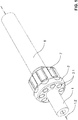
- the lighting unit is in accordance with Fig. 1 Mounted concentrically to the nozzle axis 1.2 on the abrasive nozzle 1 connected to the abrasive hose 8.
- the protective cap 2 has eight light passage recesses 2.1 through which the light of the (not in the Fig. 1 visible) illuminant 6.1 emerges as a bundle of acute-angled light cones formed coaxially to the nozzle axis 1.2.
- Fig. 2 illustrates the concentric arrangement of the components around the nozzle axis 1.2 of the blasting agent nozzle 1.
- Eight light-emitting diodes with a respective beam angle of approx. 30 ° are installed on the illuminant carrier 6 as the illuminant 6.1.
- the lamp holder 6 is attached to the Lamp housing 5 mounted, the lamps 6.1 being inserted into corresponding bores in the lamp housing 5.
- the transparent housing window 4 fastened by means of the screws 10 and the insert nuts 11 serves as the closure on the emission side.
- the lamp housing 5 is fixed against axial displacement on the stop collar 1.1 of the blasting agent nozzle 1.
- the housing cap 7, designed as a union nut, is screwed to the external thread located on the illuminant housing 5.
- the rubber-elastic protective cap 2 is pushed over the exit-side end of the blasting agent nozzle 1 against the preinstalled illuminant housing 5 on the blasting agent nozzle 1.
- the interchangeable protective pane 3 is inserted between the protective cap 2 and the housing window 4.
- the interchangeable protective screen 3 is a transparent plastic film which, after loosening or pulling off the protective cap 2, can possibly be twisted a little or completely exchanged.
- the seal 9 serves as a seal between the blasting agent nozzle 1 and the blasting agent hose 8.
- Figure 3 shows a blasting medium nozzle device for dry blasting or moist internal blasting, which has the blasting medium rebound protection 14 and the damp external blasting stage as additional modules.
- the evaluation and control electronics 12 with the operating elements 13 enable the control of the (not in the Fig. 3 visible) abrasive metering valve 15.
- FIG. 4 An abrasive dosing valve with a plug cock is in Fig. 4 shown.
- the electrically controlled plug valve has a position indicator and an emergency or manual operation.
- the plug tap is driven by a worm gear from a stepper motor which is controlled by the evaluation and control electronics 12.
Landscapes
- Engineering & Computer Science (AREA)
- Mechanical Engineering (AREA)
- Nozzles (AREA)
Abstract
Description
- Die Erfindung betrifft eine Strahlmitteldüsenvorrichtung mit einer Beleuchtungseinheit zur gezielten Beleuchtung eines Werkstücks während der Oberflächenbearbeitung mittels eines abrasiven Strahlmittels. Sie eignet sich zum Abrasivstrahlen von schlecht sichtbaren, insbesondere abgeschatteten Werkstückbereichen.
- Bekannt ist das Abrasivstrahlen mit beleuchteten Strahlmitteldüsen u. a. aus
US 4 901 928 A . Die gezielte Beleuchtung des zu strahlenden Werkstücks erfolgt demgemäß mittels einer Hochenergielichtquelle, die seitlich am Griff der Strahlmitteldüse montiert ist. Ähnliche einseitig an der Strahlmitteldüse angebrachte Beleuchtungseinheiten sind inDE 203 14 305 U1 und inDE 20 2010 007 491 U1 offenbart. - Diese bekannten Beleuchtungseinheiten gewährleisten zwar eine weitestgehend direkte Beleuchtung des zu strahlenden Bereichs. Jedoch kommt es während des Abrasivstrahlens zu Abschattungseffekten durch die Anordnung der Strahlmitteldüse relativ zur Beleuchtungseinheit. Die bei der Handhabung der Strahlmittedüse infolgedessen auftretenden Licht- und Schattenwechsel sind für das Bedienpersonal vielfach hinderlich, da die Strahlmitteldüse zusammen mit der Beleuchtungseinheit für ein zielgenaues Arbeiten immer wieder beleuchtungsgerecht ausgerichtet werden muss. Die damit verbundenen kurzen Prozessunterbrechungen verringern die Effizienz beim Abrasivstrahlen.
- Aus dem Stand der Technik ist kein System bekannt, welches der Person des Sandstrahlers erlaubt, das Strahlmittel fern vom Strahlmittelbehälter (genannt Druckstrahlkessel) zu dosieren. Nachteilig dabei ist insbesondere, dass eine unnötig große Menge Strahlmittel verbraucht wird und die Strahlergebnisse in der Qualität unterschiedlich ausfallen. Zudem geht wertvolle Arbeitszeit verloren, wenn der Sandstrahler aufgrund Verstopfungen oder vorweg falsch eingestelltem Dosierventil zu viel oder zu wenig Strahlmittel am Düsenausgang zum Sandstrahlen zur Verfügung hat und anderen Orts per Hand aufwendig und frustbeladen nachregeln muss.
- Aufgabe der Erfindung ist es daher, eine Strahlmitteldüsenvorrichtung bereitzustellen, die es erlaubt, den Strahlmittelfluss unabhängig vom Luftfluss zu steuern und/oder den Luftfluss unabhängig vom Strahlmittelfluss an- und abzuschalten, wobei die zu strahlenden Bereiche des Werkstücks abschattungsfrei beleuchtbar sein sollen.
- Diese Aufgabe wird mit einer Strahlmitteldüsenvorrichtung zur Oberflächenbearbeitung eines Werkstücks mittels eines abrasiven Strahlmittels mit den kennzeichnenden Merkmalen nach dem Anspruch 1 gelöst; zweckmäßige Weiterbildungen der Erfindung sind in den Ansprüchen 2 bis 15 aufgeführt.
- Nach Maßgabe der Erfindung umfasst die Strahlmitteldüsenvorrichtung eine Strahlmitteldüse sowie eine Beleuchtungseinheit zur gezielten Beleuchtung des Werkstücks, wobei die Beleuchtungseinheit auf einer zur Strahlmitteldüse konzentrischen Umfangslinie mehrere, gleichmäßig verteilt angeordnete Leuchtmittel aufweist, d. h., die Leuchtmittel befinden sich an Positionen auf einer radial zur Düsenachse der Strahlmitteldüse ausgebildeten Ebene, besitzen alle den gleichem Abstand zur Düsenachse und sind jeweils zueinander gleich beabstandet.
- Weiterhin weist die Strahlmitteldüsenvorrichtung ein Strahlmittelferndosiersystem auf, das ein Strahlmitteldosierventil mit elektrischem und/oder mechanischem Antrieb und eine mit demselben verbundene Auswerte- und Steuerelektronik umfasst.
- Insbesondere ist das Strahlmitteldosierventil jederzeit auch per Hand regel- und schließbar. Dies ist wichtig beim Ausfall einer elektrischen Komponente.
- In vorteilhafter Weise ist das Strahlmittelferndosiersystem direkt an der Strahlmitteldüsenvorrichtung jederzeit an- und abschaltbar. Nach dem Abschalten kann die letzte Dosiermenge gespeichert werden, um nach erneutem Anschalten wieder zur Verfügung zu stehen. Die Bedienung erfolgt komplett an der Strahlmitteldüsenvorrichtung, d. h., es ist dem Sandstrahler erlaubt, das Strahlmittel fern vom Strahlmittelbehälter, dem sog. Druckstrahlkessel, zu kontrollieren bzw. zu dosieren.
- Als Leuchtmittel dienen gerichtete Lichtquellen, deren Licht jeweils kegelförmig abstrahlt, d. h. sich im Strahlengang aufweitet. Die Abstrahlrichtung stellt nach bekannter Definition die Strahlrichtung der höchsten Lichtintensität des Lichtkegels dar. Der Abstrahlwinkel de Leuchtmittel liegt vorzugsweise im Bereich von 5° bis 55°. Als Leuchtmittel eignen sich insbesondere Leuchtdioden (LEDs).
- Erfindungsgemäß ist die Abstrahlrichtung jedes der Leuchtmittel parallel zur Strahlmitteldüse, d. h. zu ihrer Düsenachse, ausgerichtet.
- Die vorgeschlagene Strahlmitteldüsenvorrichtung zeichnet sich dadurch aus, dass von der Beleuchtungseinheit ein Bündel aus gerichteten Lichtkegeln ausgesandt wird, welches koaxial zur Strahlmitteldüse angeordnet ist. Durch die ringförmige Überlappung der sich aufweitenden, einzelnen Leuchtmittel-Lichtkegel wird der abrasiv zu strahlenden Bereich auf der Werkstückoberfläche abschattungsfrei ausgeleuchtet. Dies gewährleistet die gute Erkennbarkeit der abrasiv zu strahlende Werkstückbereiche durch das Bedienpersonal - kontinuierlich während der gesamten Dauer der Bearbeitung.
- Vorzugsweise werden vier bis zwölf Leuchtmittel gleichmäßig verteilt am Umfang der Strahlmitteldüse angeordnet.
- Die Leuchtmittel können zum Beispiel auf einem ringförmigen Leuchtmittelträger fixiert sein.
- Die Strahlmitteldüsenvorrichtung ist bevorzugt ergonomisch geformt und kompakt ausgeführt; somit ist er komfortabel bedienbar und ohne großen technischen Aufwand zu warten bzw. zu reparieren.
- Die Strahlmitteldüsenvorrichtung ist zudem so gestaltet, dass jener und die Bedienelemente, Anbauteile etc. gegen Strahlmittelrückprall gut mechanisch geschützt sind. Zusatzmodule, wie Unterdruckstufen und eine Feuchtstrahlaußenstufe, sind ohne großen technischen Aufwand montierbar, zusätzliche Düsenkombinationen sind vorsetzbar. Die Strahlmitteldüsenvorrichtung kann im Inneren außerdem über eine Wasserzumischeinheit zur Zumischung von Wasser zum Strahlmittel verfügen.
- Gemäß einer Ausgestaltung ist die Beleuchtungseinheit der Strahlmitteldüsenvorrichtung abstrahlseitig mittels einer Schutzkappe abgedeckt, in die ein oder mehrere Lichtdurchtrittsaussparungen, durch die das von den Leuchtmitteln ausgehende Licht passieren kann, eingebracht sind. Die Schutzkappe besteht vorzugsweise aus einem Gummiwerkstoff.
- Es kann vorgesehen sein, dass die Leuchtmittel in ein ringförmiges Leuchtmittelgehäuse eingesetzt sind, das in Abstrahlrichtung der Leuchtmittel mit einem ringscheibenförmigen, transparenten Gehäusefenster verschlossen ist. Das Gehäusefenster gewährleistet die Transmission des von den Leuchtmitteln ausgehenden Lichts, verhindert jedoch den Zutritt des Strahlmittels zu den Leuchtmitteln.
- Die Leuchtmittel ebenso wie das Leuchtmittelgehäuse können zudem mittels einer Gehäusekappe gegen den Zutritt von Strahlmittel verkleidet sein. Diese Gehäusekappe ist vorzugsweise als Überwurfmutter ausgeführt, die auf ein am Leuchtmittelgehäuse angebrachtes Außengewinde aufschraubbar ist.
- Alternativ können die Leuchtmittel und das Leuchtmittelgehäuse in einem Düsenhalter integriert sein.
- Weiterhin kann die Strahlmitteldüsenvorrichtung eine transparente, austauschbare Wechselschutzscheibe aufweisen, die die Leuchtmittel in ihrem Strahlengang gegen den Zutritt des Strahlmittels abdeckt. Die Wechselschutzscheibe kann zum Beispiel eine ringscheibenförmige Kunststofffolie sein. Sie ist vorzugsweise mittels der Schutzkappe abstrahlseitig vor den Leuchtmitteln bzw. vor dem Gehäusefenster installiert. Durch die Wechselschutzscheibe wird verhindert, dass die Leuchtmittel bzw. das Gehäusefenster durch auftreffende abrasive Strahlmittelkörner verschleißen. Erreicht der (unvermeidliche) Verschleiß der Wechselschutzscheibe nach einer gewissen Nutzungsdauer ein störendes Ausmaß kann die Wechselschutzscheibe zum Beispiel um wenige Grad weitergedreht werden, um nicht verschlissene Bereiche der Wechselschutzscheibe im Strahlgang der Leuchtmittel zu positionieren. Alternativ besteht die Möglichkeit, die als Verschleißteil konzipierte Wechselschutzscheibe komplett zu tauschen.
- Eine Ausgestaltung sieht vor, dass das Strahlmitteldosierventil ein Anzeigeelement aufweist, das die am Strahlmitteldosierventil eingestellte Strahlmitteldosiermenge anzeigt. Somit kann der Bediener von außen erkennen, wo die Ventilöffnung steht bzw. welche Dosiermenge eingestellt ist. Das Anzeigeelement kann elektrisch, z. B. als Leuchtdiodenreihe oder Zeigerinstrument, oder mechanisch, z. B. als sich mit dem Öffnungsgrad des Strahlmitteldosierventils über eine Skala mitbewegende Markierung, ausgestaltet sein.
- Zusätzlich kann das Strahlmitteldosierventil mit einem Nullpositionsgeber ausgerüstet sein. Außerdem ist das Strahlmitteldosierventil vorzugsweise in kleinen Stufen oder Schritten verstellbar, um den optimalen Arbeitspunkt einzustellen.
- Es kann vorgesehen sein, dass das Strahlmitteldosierventil ein Gummidosierventil ist. Allerdings ermöglicht ein Gummidosierventil, da sich der Gummi verformt, nur eine "ungefähr" punktgenaue Dosierung.
- Alternativ kann als Strahlmitteldosierventil ein Metalldosierventil eingesetzt sein. Metalldosierventile ermöglichen eine schrittweise oder stufenweise Dosierung infolge Endpunktlagenauswertung .
- Als besonders geeignet hat sich ein Kükendosierhahn erwiesen, da er folgende Bedingungen erfüllt:
- leicht zu reinigen und zu warten;
- jederzeit auch per Hand regelbar und schließbar (wichtig beim Ausfall einer elektrischen Komponente);
- der Bediener kann von außen erkennen, wo die Ventilöffnung steht;
- das Ventil weist einen Nullpositionsgeber auf; zudem ist es in kleinen Stufen oder Schritten verstellbar, um den optimalen Arbeitspunkt einzustellen.
- Gemäß einer Ausführungsform umfasst die Auswerte- und Steuerelektronik einen Datenspeicher, in welchem die am Strahlmitteldosierventil eingestellte Strahlmitteldosiermenge stromlos speicherbar ist.
- Für die Verstellung des Strahlmitteldosierventils kann ein Schrittmotor, untersetzt z. B. mit einem Schneckengetriebe, der in frei definierbaren Stufen oder Schritten das Strahlmitteldosierventil antreibt, vorgesehen sein. Es ist möglich, die gefahrenen Schritte in einem Speicher zu dokumentieren, um eine Position zu behalten und/oder zu wiederholen.
- Vorteilhaft ist, dass beim Notabschalten der Schrittmotor durch sehr schnelles Drehen das Dosierventil schließt, den Strahlmittelfluss unmittelbar stoppt und so Gefahren vermindert.
- Die Strahlmitteldüsenvorrichtung kann zudem eine automatische Strahlmitteldosierung, realisiert durch das Messen der Partikelmenge, eine umfassende Auswerteeinheit sowie Kühltechnik, besonders im Hinblick auf ein besseres Abstrahlen von Elastomeren, enthalten.
- Die Erfindung ist nachfolgend anhand von Ausführungsbeispielen und mit Bezug auf die schematischen Zeichnungen näher erläutert, wobei gleiche oder ähnliche Merkmale mit gleichen Bezugszeichen versehen sind. Dazu zeigen:
- Fig. 1:
- eine erste Ausführung der Strahlmitteldüsenvorrichtung mit Beleuchtungseinheit in perspektivischer Ansicht,
- Fig. 2:
- die erste Ausführung der Strahlmitteldüsenvorrichtung mit Beleuchtungseinheit in perspektivischer Explosionsdarstellung.
- Fig. 3:
- eine zweite Ausführung der Strahlmitteldüsenvorrichtung in perspektivischer Ansicht, und
- Fig. 4:
- eine Strahlmitteldosierventil mit Auswerte- und Steuerelektronik in perspektivischer Ansicht.
- Die Beleuchtungseinheit ist gemäß
Fig. 1 konzentrisch zur Düsenachse 1.2 auf der an den Strahlmittelschlauch 8 angeschlossenen Strahlmitteldüse 1 montiert. Durch ihre Schutzkappe 2 und ihre Gehäusekappe 7 ist die Beleuchtungseinheit gegenüber der Umgebung - und damit gegenüber dem Zutritt von Strahlmittel - abgeschirmt. Die Schutzkappe 2 besitzt acht Lichtdurchtrittsaussparungen 2.1, durch die das Licht der (nicht in derFig. 1 sichtbaren) Leuchtmittel 6.1 als ein koaxial zur Düsenachse 1.2 ausgebildetes Bündel von spitzwinkligen Lichtkegeln austritt. - Die entsprechende Explosionsdarstellung gemäß der
Fig. 2 verdeutlicht die konzentrische Anordnung der Bauteile um die Düsenachse 1.2 der Strahlmitteldüse 1. - Als Leuchtmittel 6.1 sind acht Leuchtdioden mit einem jeweiligen Abstrahlwinkel von ca. 30° auf dem Leuchtmittelträger 6 installiert. Der Leuchtmittelträger 6 wird an das Leuchtmittelgehäuse 5 montiert, wobei die Leuchtmittel 6.1 in korrespondierende Bohrungen im Leuchtmittelgehäuse 5 eingesetzt sind. Als abstrahlseitiger Verschluss dient das transparente, mittels der Schrauben 10 und der Einsatzmuttern 11 befestigte Gehäusefenster 4.
- Das Leuchtmittelgehäuse 5 ist am Anschlagbund 1.1 der Strahlmitteldüse 1 gegen axiale Verschiebung fixiert. Die als Überwurfmutter ausgebildete Gehäusekappe 7 ist mit dem am Leuchtmittelgehäuse 5 befindliche Außengewinde verschraubt.
- Die gummielastische Schutzkappe 2 wird über das austrittsseitige Ende der Strahlmitteldüse 1 gegen das vorinstallierte Leuchtmittelgehäuse 5 auf die Strahlmitteldüse 1 aufgeschoben. Um das Gehäusefenster 4 vor Verschleiß durch Strahlmittel, welches über Lichtdurchtrittsaussparungen 2.1 der Schutzkappe 2 eingetragen werden kann, zu schützen, ist zwischen der Schutzkappe 2 und dem Gehäusefenster 4 die Wechselschutzscheibe 3 eingefügt. Die Wechselschutzscheibe 3 ist eine transparente Kunststofffolie, die nach dem Lösen bzw. Abziehen der Schutzkappe 2 ggf. etwas verdreht oder komplett ausgetauscht werden kann.
- Die Dichtung 9 dient als Abdichtung der Strahlmitteldüse 1 zum Strahlmittelschlauch 8.
-
Figur 3 zeigt eine Strahlmitteldüsenvorrichtung zum Trockenstrahlen bzw. Feuchtinnenstrahlen, die als Zusatzmodule den Strahlmittelrückprallschutz 14 und die Feuchtaußenstrahlstufe aufweist. Die Auswerte- und Steuerelektronik 12 mit den Bedienelementen 13 ermöglicht die Steuerung des (nicht in derFig. 3 sichtbaren) Strahlmitteldosierventils 15. - Ein Strahlmitteldosierventil mit einem Kükenhahn ist in
Fig. 4 dargestellt. Der elektrisch geregelte Kükenhahn besitzt einen Positionsanzeiger und eine Not- bzw. Handbetätigung. Angetrieben wird der Kükenhahn über ein Schneckengetriebe von einem Schrittmotor, der von der Auswerte- und Steuerelektronik 12 angesteuert wird. -
- 1
- Strahlmitteldüse
- 1.1
- Anschlagbund
- 1.2
- Düsenachse
- 2
- Schutzkappe
- 2.1
- Lichtdurchtrittsaussparung
- 3
- Wechselschutzscheibe
- 4
- Gehäusefenster
- 5
- Leuchtmittelgehäuse
- 6
- Leuchtmittelträger
- 6.1
- Leuchtmittel
- 7
- Gehäusekappe
- 8
- Strahlmittelschlauch
- 9
- Dichtung
- 10
- Schraube
- 11
- Einsatzmutter
- 12
- Auswerte- und Steuerelektronik
- 13
- Bedienelement
- 14
- Strahlmittelrückprallschutz
- 15
- Strahlmitteldosierventil
- 16
- Feuchtaußenstrahlstufe
Claims (15)
- Strahlmitteldüsenvorrichtung zur Oberflächenbearbeitung eines Werkstücks mittels eines abrasiven Strahlmittels, umfassend eine Strahlmitteldüse (1) sowie eine Beleuchtungseinheit zur gezielten Beleuchtung des Werkstücks, dadurch gekennzeichnet, dass sie ein Strahlmittelferndosiersystem aufweist, das ein Strahlmitteldosierventil mit elektrischem und/oder mechanischem Antrieb und eine mit demselben verbundene Auswerte- und Steuerelektronik umfasst, und
die Beleuchtungseinheit auf einer zur Strahlmitteldüse (1) konzentrischen Umfangslinie mehrere, gleichmäßig verteilt angeordnete Leuchtmittel (6.1) aufweist, die als gerichtete, kegelförmig abstrahlende Lichtquellen ausgebildet sind, deren jeweilige Abstrahlrichtung parallel zur Strahlmitteldüse (1) ausgerichtet ist. - Strahlmitteldüsenvorrichtung nach Anspruch 1, dadurch gekennzeichnet, dass die Beleuchtungseinheit abstrahlseitig mittels einer Schutzkappe (2) abgedeckt ist, die eine oder mehrere Lichtdurchtrittsaussparungen (2.1) besitzt.
- Strahlmitteldüsenvorrichtung nach einem der vorstehenden Ansprüche, dadurch gekennzeichnet, dass die Leuchtmittel (6.1) im Strahlengang mittels einer transparenten, austauschbaren Wechselschutzscheibe (3) gegen den Zutritt des Strahlmittels abgedeckt sind.
- Strahlmitteldüsenvorrichtung nach Anspruch 3, dadurch gekennzeichnet, dass die Wechselschutzscheibe (3) eine ringscheibenförmige Kunststofffolie ist.
- Strahlmitteldüsenvorrichtung nach einem der vorstehenden Ansprüche, dadurch gekennzeichnet, dass die Leuchtmittel (6.1) in ein ringförmiges Leuchtmittelgehäuse (5) eingesetzt sind, das in Abstrahlrichtung der Leuchtmittel (6.1) mit einem ringscheibenförmigen, transparenten Gehäusefenster (4) verschlossen ist.
- Strahlmitteldüsenvorrichtung nach Anspruch 5, dadurch gekennzeichnet, dass die Leuchtmittel (6.1) und das Leuchtmittelgehäuse (5) mittels einer Gehäusekappe (7) gegen den Zutritt von Strahlmittel verkleidet sind.
- Strahlmitteldüsenvorrichtung nach Anspruch 6, dadurch gekennzeichnet, dass die Gehäusekappe (7) als Überwurfmutter ausgeführt ist, die auf ein am Leuchtmittelgehäuse (5) angebrachtes Außengewinde aufschraubbar ist.
- Strahlmitteldüsenvorrichtung nach einem der vorstehenden Ansprüche, dadurch gekennzeichnet, dass die Leuchtmittel (6.1) auf einem ringförmigen Leuchtmittelträger (6) fixiert sind.
- Strahlmitteldüsenvorrichtung nach einem der vorstehenden Ansprüche, dadurch gekennzeichnet, dass die Leuchtmittel (6.1) einen Abstrahlwinkel im Bereich von 5° bis 55° besitzen.
- Strahlmitteldüsenvorrichtung nach einem der vorstehenden Ansprüche, dadurch gekennzeichnet, dass die Anzahl der gleichmäßig am Umfang der Strahlmitteldüse (1) verteilt angeordneten Leuchtmittel (6.1) im Bereich von 4 bis 12 liegt.
- Strahlmitteldüsenvorrichtung nach einem der vorstehenden Ansprüche, dadurch gekennzeichnet, dass die Auswerte- und Steuerelektronik einen Datenspeicher umfasst, in welchem die eingestellte Strahlmitteldosiermenge stromlos speicherbar ist.
- Strahlmitteldüsenvorrichtung nach einem der vorstehenden Ansprüche, dadurch gekennzeichnet, dass sie eine Wasserzumischeinheit umfasst.
- Strahlmitteldüsenvorrichtung nach einem der vorstehenden Ansprüche, dadurch gekennzeichnet, dass das Strahlmitteldosierventil ein Gummidosierventil oder ein Metalldosierventil ist.
- Strahlmitteldüsenvorrichtung nach einem der vorstehenden Ansprüche, dadurch gekennzeichnet, dass das Strahlmitteldosierventil ein Anzeigeelement aufweist, das die am Strahlmitteldosierventil eingestellte Strahlmitteldosiermenge anzeigt.
- Strahlmitteldüsenvorrichtung nach einem der vorstehenden Ansprüche, dadurch gekennzeichnet, dass sie einen Schrittmotor umfasst, der über ein Untersetzungsgetriebe mit dem Strahlmitteldosierventil verbunden ist.
Applications Claiming Priority (3)
| Application Number | Priority Date | Filing Date | Title |
|---|---|---|---|
| DE202019105904.4U DE202019105904U1 (de) | 2019-10-24 | 2019-10-24 | Strahlmitteldüsenvorrichtung mit Beleuchtungseinheit |
| DE102019129881.4A DE102019129881A1 (de) | 2019-10-24 | 2019-11-06 | Strahlmitteldüsenvorrichtung mit Beleuchtungseinheit |
| DE102020126137 | 2020-10-06 |
Publications (3)
| Publication Number | Publication Date |
|---|---|
| EP3812095A1 true EP3812095A1 (de) | 2021-04-28 |
| EP3812095C0 EP3812095C0 (de) | 2024-05-01 |
| EP3812095B1 EP3812095B1 (de) | 2024-05-01 |
Family
ID=73014312
Family Applications (1)
| Application Number | Title | Priority Date | Filing Date |
|---|---|---|---|
| EP20203589.5A Active EP3812095B1 (de) | 2019-10-24 | 2020-10-23 | Strahlmitteldüsenvorrichtung mit beleuchtungseinheit |
Country Status (2)
| Country | Link |
|---|---|
| EP (1) | EP3812095B1 (de) |
| PL (1) | PL3812095T3 (de) |
Citations (9)
| Publication number | Priority date | Publication date | Assignee | Title |
|---|---|---|---|---|
| US4901928A (en) | 1988-10-04 | 1990-02-20 | Stripping Technologies Inc. | Pressure hose handle and system |
| US5024029A (en) * | 1988-10-04 | 1991-06-18 | Stripping Technologies Inc. | Abrasive media valve system |
| US5801454A (en) * | 1994-12-02 | 1998-09-01 | Leininger; Jon J. | Air tool |
| DE19738572A1 (de) * | 1997-09-04 | 1999-03-25 | Fastje Ines | Dosierventil, insbesondere für ein Druckstrahlgerät, Druckstrahlgerät sowie Verfahren zum Betrieb eines Druckstrahlgeräts |
| DE20314305U1 (de) | 2003-09-15 | 2004-01-08 | Heinrich Schlick Gmbh | Bedieneinheit für eine Strahlmitteldüse |
| DE202010007491U1 (de) | 2010-06-01 | 2011-10-19 | BEGO Bremer Goldschlägerei Wilh. Herbst GmbH & Co. KG | Strahlmitteldüsenvorrichtung |
| KR101378978B1 (ko) * | 2012-05-25 | 2014-03-28 | 삼성중공업 주식회사 | 블라스팅 노즐 장치 |
| US20180264625A1 (en) * | 2015-01-22 | 2018-09-20 | Volker Schneidau | Control of particle supply of blasting apparatus |
| FR3071175A1 (fr) * | 2017-09-20 | 2019-03-22 | Transalpin Innovative System | Systeme de controle d'une lance de projection permettant d'assurer la securite de l'operateur manipulant la lance |
Family Cites Families (1)
| Publication number | Priority date | Publication date | Assignee | Title |
|---|---|---|---|---|
| US5873647A (en) * | 1997-03-27 | 1999-02-23 | Kurtz; Rodney | Nozzle mounted lamp |
-
2020
- 2020-10-23 EP EP20203589.5A patent/EP3812095B1/de active Active
- 2020-10-23 PL PL20203589.5T patent/PL3812095T3/pl unknown
Patent Citations (9)
| Publication number | Priority date | Publication date | Assignee | Title |
|---|---|---|---|---|
| US4901928A (en) | 1988-10-04 | 1990-02-20 | Stripping Technologies Inc. | Pressure hose handle and system |
| US5024029A (en) * | 1988-10-04 | 1991-06-18 | Stripping Technologies Inc. | Abrasive media valve system |
| US5801454A (en) * | 1994-12-02 | 1998-09-01 | Leininger; Jon J. | Air tool |
| DE19738572A1 (de) * | 1997-09-04 | 1999-03-25 | Fastje Ines | Dosierventil, insbesondere für ein Druckstrahlgerät, Druckstrahlgerät sowie Verfahren zum Betrieb eines Druckstrahlgeräts |
| DE20314305U1 (de) | 2003-09-15 | 2004-01-08 | Heinrich Schlick Gmbh | Bedieneinheit für eine Strahlmitteldüse |
| DE202010007491U1 (de) | 2010-06-01 | 2011-10-19 | BEGO Bremer Goldschlägerei Wilh. Herbst GmbH & Co. KG | Strahlmitteldüsenvorrichtung |
| KR101378978B1 (ko) * | 2012-05-25 | 2014-03-28 | 삼성중공업 주식회사 | 블라스팅 노즐 장치 |
| US20180264625A1 (en) * | 2015-01-22 | 2018-09-20 | Volker Schneidau | Control of particle supply of blasting apparatus |
| FR3071175A1 (fr) * | 2017-09-20 | 2019-03-22 | Transalpin Innovative System | Systeme de controle d'une lance de projection permettant d'assurer la securite de l'operateur manipulant la lance |
Also Published As
| Publication number | Publication date |
|---|---|
| EP3812095C0 (de) | 2024-05-01 |
| EP3812095B1 (de) | 2024-05-01 |
| PL3812095T3 (pl) | 2024-08-19 |
Similar Documents
| Publication | Publication Date | Title |
|---|---|---|
| DE102014213283A1 (de) | Kamerasystem für ein Fahrzeug | |
| DE69002640T2 (de) | Elektrostatisches Sprühbeschichtungsgerät mit Rotationszerstäuber. | |
| DE3521638C2 (de) | Streuwindsichter zum Sichten von feinkörnigem Gut | |
| DE212016000027U1 (de) | Spritzpistole | |
| DE2606798A1 (de) | Geraet zur pneumatischen entfernung von staub | |
| DE102021125754A1 (de) | Strahlmitteldüsenvorrichtung mit Beleuchtungseinheit | |
| DE102009044860B3 (de) | Elektrodenschleifvorrichtung | |
| EP3812095B1 (de) | Strahlmitteldüsenvorrichtung mit beleuchtungseinheit | |
| CH713471A1 (de) | Vorrichtung zum Bearbeiten von Beschichtungen, Graffiti oder sonstigen oberflächigen Verunreinigungen auf Teilen, Werkstücken oder Flächen. | |
| DE102017207459A1 (de) | Reinigungsvorrichtung für reinräume | |
| EP2650052A1 (de) | Pulverbechersprühpistole und Sprühbeschichtungsvorrichtung mit einer Pulverbechersprühpistole | |
| DE8632832U1 (de) | Strömungswächter | |
| EP1413397A1 (de) | Einrichtung zum Bearbeiten des Randes eines Gegenstandes | |
| DE19800154C2 (de) | Hohlstrahldüse | |
| DE102019129881A1 (de) | Strahlmitteldüsenvorrichtung mit Beleuchtungseinheit | |
| DE1117440B (de) | Motorisch angetriebenes Handwerkzeug zum Entfleischen von Knochen | |
| EP2922663A1 (de) | Vorrichtung zum markieren einer schraube oder eines schraubenkopfs | |
| DE202010007491U1 (de) | Strahlmitteldüsenvorrichtung | |
| DE4301159C1 (de) | Vorrichtung für die Belüftung und Beleuchtung eines Raumes oder eines Raumbereiches | |
| DE8914346U1 (de) | Motorisch zu einer Rotationsbewegung antreibbares Werkzeug | |
| DE10039496C2 (de) | Anschlusszwischenstück für Wasserleitungen mit Bypass | |
| DE102011001745B4 (de) | Strahlkopf | |
| DE102004012128B4 (de) | UV-Bestrahlungsvorrichtung, insbesondere UV-Handbestrahlungsvorrichtung | |
| DE3644563A1 (de) | Lupenleuchte | |
| DE102024131975A1 (de) | Schneidwerkzeug |
Legal Events
| Date | Code | Title | Description |
|---|---|---|---|
| PUAI | Public reference made under article 153(3) epc to a published international application that has entered the european phase |
Free format text: ORIGINAL CODE: 0009012 |
|
| STAA | Information on the status of an ep patent application or granted ep patent |
Free format text: STATUS: THE APPLICATION HAS BEEN PUBLISHED |
|
| AK | Designated contracting states |
Kind code of ref document: A1 Designated state(s): AL AT BE BG CH CY CZ DE DK EE ES FI FR GB GR HR HU IE IS IT LI LT LU LV MC MK MT NL NO PL PT RO RS SE SI SK SM TR |
|
| AX | Request for extension of the european patent |
Extension state: BA ME |
|
| STAA | Information on the status of an ep patent application or granted ep patent |
Free format text: STATUS: REQUEST FOR EXAMINATION WAS MADE |
|
| 17P | Request for examination filed |
Effective date: 20211026 |
|
| RBV | Designated contracting states (corrected) |
Designated state(s): AL AT BE BG CH CY CZ DE DK EE ES FI FR GB GR HR HU IE IS IT LI LT LU LV MC MK MT NL NO PL PT RO RS SE SI SK SM TR |
|
| STAA | Information on the status of an ep patent application or granted ep patent |
Free format text: STATUS: EXAMINATION IS IN PROGRESS |
|
| 17Q | First examination report despatched |
Effective date: 20230809 |
|
| GRAP | Despatch of communication of intention to grant a patent |
Free format text: ORIGINAL CODE: EPIDOSNIGR1 |
|
| STAA | Information on the status of an ep patent application or granted ep patent |
Free format text: STATUS: GRANT OF PATENT IS INTENDED |
|
| RIC1 | Information provided on ipc code assigned before grant |
Ipc: B25H 1/00 20060101ALN20231206BHEP Ipc: B23Q 17/24 20060101ALN20231206BHEP Ipc: F21V 33/00 20060101ALN20231206BHEP Ipc: B24C 7/00 20060101ALI20231206BHEP Ipc: B24C 9/00 20060101ALI20231206BHEP Ipc: B24C 5/02 20060101AFI20231206BHEP |
|
| INTG | Intention to grant announced |
Effective date: 20231221 |
|
| GRAS | Grant fee paid |
Free format text: ORIGINAL CODE: EPIDOSNIGR3 |
|
| GRAA | (expected) grant |
Free format text: ORIGINAL CODE: 0009210 |
|
| STAA | Information on the status of an ep patent application or granted ep patent |
Free format text: STATUS: THE PATENT HAS BEEN GRANTED |
|
| AK | Designated contracting states |
Kind code of ref document: B1 Designated state(s): AL AT BE BG CH CY CZ DE DK EE ES FI FR GB GR HR HU IE IS IT LI LT LU LV MC MK MT NL NO PL PT RO RS SE SI SK SM TR |
|
| REG | Reference to a national code |
Ref country code: GB Ref legal event code: FG4D Free format text: NOT ENGLISH |
|
| REG | Reference to a national code |
Ref country code: CH Ref legal event code: EP |
|
| REG | Reference to a national code |
Ref country code: DE Ref legal event code: R096 Ref document number: 502020007823 Country of ref document: DE |
|
| REG | Reference to a national code |
Ref country code: IE Ref legal event code: FG4D Free format text: LANGUAGE OF EP DOCUMENT: GERMAN |
|
| U01 | Request for unitary effect filed |
Effective date: 20240508 |
|
| U07 | Unitary effect registered |
Designated state(s): AT BE BG DE DK EE FI FR IT LT LU LV MT NL PT SE SI Effective date: 20240523 |
|
| PG25 | Lapsed in a contracting state [announced via postgrant information from national office to epo] |
Ref country code: IS Free format text: LAPSE BECAUSE OF FAILURE TO SUBMIT A TRANSLATION OF THE DESCRIPTION OR TO PAY THE FEE WITHIN THE PRESCRIBED TIME-LIMIT Effective date: 20240901 |
|
| PG25 | Lapsed in a contracting state [announced via postgrant information from national office to epo] |
Ref country code: HR Free format text: LAPSE BECAUSE OF FAILURE TO SUBMIT A TRANSLATION OF THE DESCRIPTION OR TO PAY THE FEE WITHIN THE PRESCRIBED TIME-LIMIT Effective date: 20240501 |
|
| PG25 | Lapsed in a contracting state [announced via postgrant information from national office to epo] |
Ref country code: GR Free format text: LAPSE BECAUSE OF FAILURE TO SUBMIT A TRANSLATION OF THE DESCRIPTION OR TO PAY THE FEE WITHIN THE PRESCRIBED TIME-LIMIT Effective date: 20240802 |
|
| U79 | Statement concerning licences of right filed [unitary effect] |
Effective date: 20240909 |
|
| PG25 | Lapsed in a contracting state [announced via postgrant information from national office to epo] |
Ref country code: ES Free format text: LAPSE BECAUSE OF FAILURE TO SUBMIT A TRANSLATION OF THE DESCRIPTION OR TO PAY THE FEE WITHIN THE PRESCRIBED TIME-LIMIT Effective date: 20240501 |
|
| PG25 | Lapsed in a contracting state [announced via postgrant information from national office to epo] |
Ref country code: NO Free format text: LAPSE BECAUSE OF FAILURE TO SUBMIT A TRANSLATION OF THE DESCRIPTION OR TO PAY THE FEE WITHIN THE PRESCRIBED TIME-LIMIT Effective date: 20240801 Ref country code: IS Free format text: LAPSE BECAUSE OF FAILURE TO SUBMIT A TRANSLATION OF THE DESCRIPTION OR TO PAY THE FEE WITHIN THE PRESCRIBED TIME-LIMIT Effective date: 20240901 Ref country code: HR Free format text: LAPSE BECAUSE OF FAILURE TO SUBMIT A TRANSLATION OF THE DESCRIPTION OR TO PAY THE FEE WITHIN THE PRESCRIBED TIME-LIMIT Effective date: 20240501 Ref country code: GR Free format text: LAPSE BECAUSE OF FAILURE TO SUBMIT A TRANSLATION OF THE DESCRIPTION OR TO PAY THE FEE WITHIN THE PRESCRIBED TIME-LIMIT Effective date: 20240802 Ref country code: ES Free format text: LAPSE BECAUSE OF FAILURE TO SUBMIT A TRANSLATION OF THE DESCRIPTION OR TO PAY THE FEE WITHIN THE PRESCRIBED TIME-LIMIT Effective date: 20240501 Ref country code: RS Free format text: LAPSE BECAUSE OF FAILURE TO SUBMIT A TRANSLATION OF THE DESCRIPTION OR TO PAY THE FEE WITHIN THE PRESCRIBED TIME-LIMIT Effective date: 20240801 |
|
| U20 | Renewal fee for the european patent with unitary effect paid |
Year of fee payment: 5 Effective date: 20241004 |
|
| PG25 | Lapsed in a contracting state [announced via postgrant information from national office to epo] |
Ref country code: CZ Free format text: LAPSE BECAUSE OF FAILURE TO SUBMIT A TRANSLATION OF THE DESCRIPTION OR TO PAY THE FEE WITHIN THE PRESCRIBED TIME-LIMIT Effective date: 20240501 |
|
| PG25 | Lapsed in a contracting state [announced via postgrant information from national office to epo] |
Ref country code: SK Free format text: LAPSE BECAUSE OF FAILURE TO SUBMIT A TRANSLATION OF THE DESCRIPTION OR TO PAY THE FEE WITHIN THE PRESCRIBED TIME-LIMIT Effective date: 20240501 Ref country code: RO Free format text: LAPSE BECAUSE OF FAILURE TO SUBMIT A TRANSLATION OF THE DESCRIPTION OR TO PAY THE FEE WITHIN THE PRESCRIBED TIME-LIMIT Effective date: 20240501 |
|
| PG25 | Lapsed in a contracting state [announced via postgrant information from national office to epo] |
Ref country code: SM Free format text: LAPSE BECAUSE OF FAILURE TO SUBMIT A TRANSLATION OF THE DESCRIPTION OR TO PAY THE FEE WITHIN THE PRESCRIBED TIME-LIMIT Effective date: 20240501 |
|
| PG25 | Lapsed in a contracting state [announced via postgrant information from national office to epo] |
Ref country code: SM Free format text: LAPSE BECAUSE OF FAILURE TO SUBMIT A TRANSLATION OF THE DESCRIPTION OR TO PAY THE FEE WITHIN THE PRESCRIBED TIME-LIMIT Effective date: 20240501 Ref country code: SK Free format text: LAPSE BECAUSE OF FAILURE TO SUBMIT A TRANSLATION OF THE DESCRIPTION OR TO PAY THE FEE WITHIN THE PRESCRIBED TIME-LIMIT Effective date: 20240501 Ref country code: RO Free format text: LAPSE BECAUSE OF FAILURE TO SUBMIT A TRANSLATION OF THE DESCRIPTION OR TO PAY THE FEE WITHIN THE PRESCRIBED TIME-LIMIT Effective date: 20240501 Ref country code: CZ Free format text: LAPSE BECAUSE OF FAILURE TO SUBMIT A TRANSLATION OF THE DESCRIPTION OR TO PAY THE FEE WITHIN THE PRESCRIBED TIME-LIMIT Effective date: 20240501 |
|
| REG | Reference to a national code |
Ref country code: DE Ref legal event code: R097 Ref document number: 502020007823 Country of ref document: DE |
|
| PLBE | No opposition filed within time limit |
Free format text: ORIGINAL CODE: 0009261 |
|
| STAA | Information on the status of an ep patent application or granted ep patent |
Free format text: STATUS: NO OPPOSITION FILED WITHIN TIME LIMIT |
|
| 26N | No opposition filed |
Effective date: 20250204 |
|
| PG25 | Lapsed in a contracting state [announced via postgrant information from national office to epo] |
Ref country code: MC Free format text: LAPSE BECAUSE OF FAILURE TO SUBMIT A TRANSLATION OF THE DESCRIPTION OR TO PAY THE FEE WITHIN THE PRESCRIBED TIME-LIMIT Effective date: 20240501 |
|
| PG25 | Lapsed in a contracting state [announced via postgrant information from national office to epo] |
Ref country code: IE Free format text: LAPSE BECAUSE OF NON-PAYMENT OF DUE FEES Effective date: 20241023 |
|
| REG | Reference to a national code |
Ref country code: CH Ref legal event code: U11 Free format text: ST27 STATUS EVENT CODE: U-0-0-U10-U11 (AS PROVIDED BY THE NATIONAL OFFICE) Effective date: 20251101 |
|
| U20 | Renewal fee for the european patent with unitary effect paid |
Year of fee payment: 6 Effective date: 20251010 |
|
| PGFP | Annual fee paid to national office [announced via postgrant information from national office to epo] |
Ref country code: GB Payment date: 20251024 Year of fee payment: 6 |
|
| PGFP | Annual fee paid to national office [announced via postgrant information from national office to epo] |
Ref country code: CH Payment date: 20251101 Year of fee payment: 6 |
|
| PGFP | Annual fee paid to national office [announced via postgrant information from national office to epo] |
Ref country code: PL Payment date: 20251014 Year of fee payment: 6 |
|
| PG25 | Lapsed in a contracting state [announced via postgrant information from national office to epo] |
Ref country code: CY Free format text: LAPSE BECAUSE OF FAILURE TO SUBMIT A TRANSLATION OF THE DESCRIPTION OR TO PAY THE FEE WITHIN THE PRESCRIBED TIME-LIMIT; INVALID AB INITIO Effective date: 20201023 |
|
| PG25 | Lapsed in a contracting state [announced via postgrant information from national office to epo] |
Ref country code: HU Free format text: LAPSE BECAUSE OF FAILURE TO SUBMIT A TRANSLATION OF THE DESCRIPTION OR TO PAY THE FEE WITHIN THE PRESCRIBED TIME-LIMIT; INVALID AB INITIO Effective date: 20201023 |