EP3810472B1 - Verfahren zum betreiben eines fahrzeugs und steuergerät - Google Patents
Verfahren zum betreiben eines fahrzeugs und steuergerät Download PDFInfo
- Publication number
- EP3810472B1 EP3810472B1 EP19724747.1A EP19724747A EP3810472B1 EP 3810472 B1 EP3810472 B1 EP 3810472B1 EP 19724747 A EP19724747 A EP 19724747A EP 3810472 B1 EP3810472 B1 EP 3810472B1
- Authority
- EP
- European Patent Office
- Prior art keywords
- distance
- vehicle
- accelerator pedal
- speed
- adaptive cruise
- Prior art date
- Legal status (The legal status is an assumption and is not a legal conclusion. Google has not performed a legal analysis and makes no representation as to the accuracy of the status listed.)
- Active
Links
Images
Classifications
-
- B—PERFORMING OPERATIONS; TRANSPORTING
- B60—VEHICLES IN GENERAL
- B60W—CONJOINT CONTROL OF VEHICLE SUB-UNITS OF DIFFERENT TYPE OR DIFFERENT FUNCTION; CONTROL SYSTEMS SPECIALLY ADAPTED FOR HYBRID VEHICLES; ROAD VEHICLE DRIVE CONTROL SYSTEMS FOR PURPOSES NOT RELATED TO THE CONTROL OF A PARTICULAR SUB-UNIT
- B60W30/00—Purposes of road vehicle drive control systems not related to the control of a particular sub-unit, e.g. of systems using conjoint control of vehicle sub-units
- B60W30/14—Adaptive cruise control
- B60W30/16—Control of distance between vehicles, e.g. keeping a distance to preceding vehicle
-
- B—PERFORMING OPERATIONS; TRANSPORTING
- B60—VEHICLES IN GENERAL
- B60W—CONJOINT CONTROL OF VEHICLE SUB-UNITS OF DIFFERENT TYPE OR DIFFERENT FUNCTION; CONTROL SYSTEMS SPECIALLY ADAPTED FOR HYBRID VEHICLES; ROAD VEHICLE DRIVE CONTROL SYSTEMS FOR PURPOSES NOT RELATED TO THE CONTROL OF A PARTICULAR SUB-UNIT
- B60W40/00—Estimation or calculation of non-directly measurable driving parameters for road vehicle drive control systems not related to the control of a particular sub unit, e.g. by using mathematical models
- B60W40/08—Estimation or calculation of non-directly measurable driving parameters for road vehicle drive control systems not related to the control of a particular sub unit, e.g. by using mathematical models related to drivers or passengers
-
- B—PERFORMING OPERATIONS; TRANSPORTING
- B60—VEHICLES IN GENERAL
- B60W—CONJOINT CONTROL OF VEHICLE SUB-UNITS OF DIFFERENT TYPE OR DIFFERENT FUNCTION; CONTROL SYSTEMS SPECIALLY ADAPTED FOR HYBRID VEHICLES; ROAD VEHICLE DRIVE CONTROL SYSTEMS FOR PURPOSES NOT RELATED TO THE CONTROL OF A PARTICULAR SUB-UNIT
- B60W40/00—Estimation or calculation of non-directly measurable driving parameters for road vehicle drive control systems not related to the control of a particular sub unit, e.g. by using mathematical models
- B60W40/10—Estimation or calculation of non-directly measurable driving parameters for road vehicle drive control systems not related to the control of a particular sub unit, e.g. by using mathematical models related to vehicle motion
- B60W40/105—Speed
-
- B—PERFORMING OPERATIONS; TRANSPORTING
- B60—VEHICLES IN GENERAL
- B60W—CONJOINT CONTROL OF VEHICLE SUB-UNITS OF DIFFERENT TYPE OR DIFFERENT FUNCTION; CONTROL SYSTEMS SPECIALLY ADAPTED FOR HYBRID VEHICLES; ROAD VEHICLE DRIVE CONTROL SYSTEMS FOR PURPOSES NOT RELATED TO THE CONTROL OF A PARTICULAR SUB-UNIT
- B60W50/00—Details of control systems for road vehicle drive control not related to the control of a particular sub-unit, e.g. process diagnostic or vehicle driver interfaces
- B60W50/08—Interaction between the driver and the control system
- B60W50/087—Interaction between the driver and the control system where the control system corrects or modifies a request from the driver
-
- B—PERFORMING OPERATIONS; TRANSPORTING
- B60—VEHICLES IN GENERAL
- B60W—CONJOINT CONTROL OF VEHICLE SUB-UNITS OF DIFFERENT TYPE OR DIFFERENT FUNCTION; CONTROL SYSTEMS SPECIALLY ADAPTED FOR HYBRID VEHICLES; ROAD VEHICLE DRIVE CONTROL SYSTEMS FOR PURPOSES NOT RELATED TO THE CONTROL OF A PARTICULAR SUB-UNIT
- B60W50/00—Details of control systems for road vehicle drive control not related to the control of a particular sub-unit, e.g. process diagnostic or vehicle driver interfaces
- B60W50/08—Interaction between the driver and the control system
- B60W50/10—Interpretation of driver requests or demands
-
- B—PERFORMING OPERATIONS; TRANSPORTING
- B60—VEHICLES IN GENERAL
- B60W—CONJOINT CONTROL OF VEHICLE SUB-UNITS OF DIFFERENT TYPE OR DIFFERENT FUNCTION; CONTROL SYSTEMS SPECIALLY ADAPTED FOR HYBRID VEHICLES; ROAD VEHICLE DRIVE CONTROL SYSTEMS FOR PURPOSES NOT RELATED TO THE CONTROL OF A PARTICULAR SUB-UNIT
- B60W60/00—Drive control systems specially adapted for autonomous road vehicles
- B60W60/001—Planning or execution of driving tasks
-
- B—PERFORMING OPERATIONS; TRANSPORTING
- B60—VEHICLES IN GENERAL
- B60W—CONJOINT CONTROL OF VEHICLE SUB-UNITS OF DIFFERENT TYPE OR DIFFERENT FUNCTION; CONTROL SYSTEMS SPECIALLY ADAPTED FOR HYBRID VEHICLES; ROAD VEHICLE DRIVE CONTROL SYSTEMS FOR PURPOSES NOT RELATED TO THE CONTROL OF A PARTICULAR SUB-UNIT
- B60W50/00—Details of control systems for road vehicle drive control not related to the control of a particular sub-unit, e.g. process diagnostic or vehicle driver interfaces
- B60W2050/0062—Adapting control system settings
- B60W2050/0075—Automatic parameter input, automatic initialising or calibrating means
- B60W2050/0095—Automatic control mode change
-
- B—PERFORMING OPERATIONS; TRANSPORTING
- B60—VEHICLES IN GENERAL
- B60W—CONJOINT CONTROL OF VEHICLE SUB-UNITS OF DIFFERENT TYPE OR DIFFERENT FUNCTION; CONTROL SYSTEMS SPECIALLY ADAPTED FOR HYBRID VEHICLES; ROAD VEHICLE DRIVE CONTROL SYSTEMS FOR PURPOSES NOT RELATED TO THE CONTROL OF A PARTICULAR SUB-UNIT
- B60W2520/00—Input parameters relating to overall vehicle dynamics
- B60W2520/10—Longitudinal speed
-
- B—PERFORMING OPERATIONS; TRANSPORTING
- B60—VEHICLES IN GENERAL
- B60W—CONJOINT CONTROL OF VEHICLE SUB-UNITS OF DIFFERENT TYPE OR DIFFERENT FUNCTION; CONTROL SYSTEMS SPECIALLY ADAPTED FOR HYBRID VEHICLES; ROAD VEHICLE DRIVE CONTROL SYSTEMS FOR PURPOSES NOT RELATED TO THE CONTROL OF A PARTICULAR SUB-UNIT
- B60W2540/00—Input parameters relating to occupants
- B60W2540/10—Accelerator pedal position
-
- B—PERFORMING OPERATIONS; TRANSPORTING
- B60—VEHICLES IN GENERAL
- B60W—CONJOINT CONTROL OF VEHICLE SUB-UNITS OF DIFFERENT TYPE OR DIFFERENT FUNCTION; CONTROL SYSTEMS SPECIALLY ADAPTED FOR HYBRID VEHICLES; ROAD VEHICLE DRIVE CONTROL SYSTEMS FOR PURPOSES NOT RELATED TO THE CONTROL OF A PARTICULAR SUB-UNIT
- B60W2540/00—Input parameters relating to occupants
- B60W2540/12—Brake pedal position
Definitions
- the invention relates to a method for operating a vehicle and a control device for a vehicle.
- engine power is regulated so that a set target speed is maintained.
- engine power is regulated so that a situation-dependent target distance from a vehicle in front is maintained. If a driver of the vehicle exceeds the adaptive cruise control by operating an accelerator pedal, engine power is increased according to the angle of the accelerator pedal. If the driver presses a brake pedal on the vehicle, adaptive cruise control is deactivated.
- US 2004/195022 A1 describes a drive control unit for a vehicle.
- DE 10 2007 031543 A1 describes a method for specifying a target distance when controlling the speed to a predetermined target distance.
- JP 2010 143323 A describes a control system for controlling distances between vehicles.
- Embodiments of the present invention can advantageously make it possible to prevent a collision with a vehicle ahead even when a vehicle's adaptive cruise control is exceeded.
- a method for operating a vehicle wherein when the adaptive cruise control is activated, in response to an acceleration request from a driver of the vehicle indicated by depressing an accelerator pedal of the vehicle, a switch is made to an accelerator pedal-controlled distance controller, wherein the adaptive cruise control regulates a power target value for driving the vehicle depending on a current speed of the vehicle and depending on a current distance to a vehicle in front in such a way that the distance remains within a distance tolerance range if the distance essentially corresponds to a speed-dependent target distance, wherein the distance controller converts the acceleration request into the power target value depending on the current distance, wherein a change in the power target value becomes smaller the closer the current distance is to a distance target value, wherein the distance target value is smaller than the target distance, characterized in that in response to an end of the acceleration request, a switch is made from the accelerator pedal-controlled distance controller back to using the adaptive cruise control, so that the vehicle can again travel at the target distance to the Another vehicle moves as soon as the driver takes his foot off the accelerator pedal.
- Adaptive cruise control can be understood as a controller in a vehicle's control unit that regulates a power setpoint for driving the vehicle depending on the current speed of the vehicle and the current distance to a vehicle driving ahead.
- the vehicle driving ahead can be referred to as a foreign vehicle.
- the power setpoint is regulated by the adaptive cruise control until the current speed reaches a set target speed. If the speed essentially corresponds to the target speed, the adaptive cruise control regulates the power setpoint so that the speed remains within a set speed tolerance range around the target speed. If the speed is less than the target speed, the power setpoint is increased. If the speed is greater than the target speed, the power setpoint is reduced. The speed is kept within the speed tolerance range as long as the current distance to a vehicle ahead is greater than a predefined, speed-dependent target distance. If the distance essentially corresponds to the target distance, the power setpoint is regulated by the adaptive cruise control so that the distance remains within a distance tolerance range. If the distance is greater than the target distance, the power setpoint is increased.
- the power setpoint is reduced. If the distance decreases faster than can be compensated by the reduced power setpoint, a braking system of the vehicle is activated to increase the distance back to the setpoint.
- the distance can be expressed by a speed-independent time slot, since the distance traveled per unit of time depends on the speed.
- a driver's desire to accelerate is detected via the vehicle's accelerator pedal.
- An over-pressing of the accelerator pedal is detected if, for example, the current angle of the accelerator pedal is greater than an angle that corresponds to the power target value currently set by the adaptive cruise control.
- An accelerator pedal-controlled distance controller can be a controller in the control unit.
- the distance controller converts the acceleration request into the power target value depending on the current distance.
- a change in the acceleration request is converted into a change in the power target value depending on the current distance. The closer the current distance is to a distance target value, the smaller the change in the power target value. If the other vehicle brakes and the distance target value is not maintained, the acceleration request is reduced and, if necessary, a braking system in the vehicle is activated to brake the vehicle as well.
- acceleration request 0
- the distance target value is less than the target distance.
- the system switches from the accelerator pedal-controlled distance control mode back to using the adaptive cruise control. This means that the vehicle can drive at the target distance from the other vehicle again, or the vehicle can drive at the target speed again as soon as the driver takes their foot off the accelerator pedal.
- the distance target value to the vehicle ahead can be set depending on the acceleration request.
- the distance target value can be set in time slots.
- the smallest distance target value corresponds to a minimum safety distance.
- the greater the acceleration request, the The distance target value can be set smaller. For overtaking maneuvers, a smaller distance can be set than for a constant following on the motorway.
- the method can be implemented, for example, in software or hardware or in a mixed form of software and hardware, for example in a control unit.
- the approach presented here further creates a control unit for a vehicle that is designed to carry out, control or implement the steps of a variant of the method presented here in corresponding devices.
- the control unit can be an electrical device with at least one computing unit for processing signals or data, at least one storage unit for storing signals or data, and at least one interface and/or a communication interface for reading in or outputting data that is embedded in a communication protocol.
- the computing unit can be, for example, a signal processor, a so-called system ASIC or a microcontroller for processing sensor signals and outputting data signals depending on the sensor signals.
- the storage unit can be, for example, a flash memory, an EPROM or a magnetic storage unit.
- the interface can be designed as a sensor interface for reading in the sensor signals from a sensor and/or as an actuator interface for outputting the data signals and/or control signals to an actuator.
- the communication interface can be designed to read in or output the data wirelessly and/or via a cable.
- the interfaces can also be software modules that are present, for example, on a microcontroller alongside other software modules.
- a computer program product or computer program with program code that can be stored on a machine-readable carrier or storage medium such as a semiconductor memory, a hard disk memory or an optical memory and is used to carry out, implement and/or control the steps of the method according to one of the embodiments described above, in particular when the program product or program is executed on a computer or device.
- Cruise Control CrCtl
- LLim Longitudinal Limiter
- ALLim Advanced Longitudinal Limiter
- ACC Adaptive Cruise Control
- other assistance functions increase safety through distance warnings and emergency braking interventions.
- the ACC functionality is designed to be more cautious in certain situations than some drivers would drive themselves. In these situations, the driver has the option of requesting more torque than the ACC function in a conventional system using the accelerator pedal. However, this results in the conventional ACC function being inactive (override status) and focusing on vehicles ahead. objects. For example, when overtaking on the motorway, if you press the accelerator pedal too hard, the braking of the vehicle you are overtaking may not be taken into account and your own vehicle will therefore not brake.
- the existing ACC function is supplemented by a collision protection system (Dynamic Distance/Drive Assist, DDA) with a distance and/or speed buffer that is dynamically adapted to the driver's wishes.
- DDA Dynamic Distance/Drive Assist
- the DDA function is used in the event of an overstepping. This gives the driver the opportunity to accelerate, but is still protected by maintaining a desired distance if the vehicle being overtaken brakes.
- the DDA can be set to a small time gap or continuously adjust the target distance to the accelerator pedal request. The latter means that the driver is hardly/not restricted when accelerating using the accelerator pedal, but is braked or protected when the vehicle ahead brakes.
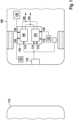
- Fig. 1 shows a representation of a vehicle 100 with a control unit 102 according to an embodiment.
- a distance control cruise control 104 and a distance controller 106 are implemented in the control unit 102.
- the control unit 102 can have further functions not described here.
- the adaptive cruise control 104 is a controller for a power setpoint 108 of the vehicle 100.
- the power setpoint 108 represents a power to be delivered by a drive of the vehicle 100.
- the adaptive cruise control 104 When the adaptive cruise control 104 is active, it regulates the delivered power depending on a current speed of the vehicle 100 and a current distance between the vehicle and a vehicle driving ahead 110.
- the adaptive cruise control 104 reads a speed value 112 and a distance value 114.
- the speed value 112 represents the current speed.
- the distance value 114 represents the current distance to the preceding vehicle 110.
- the current distance is measured by a distance sensor 116 of the vehicle 100.
- the adaptive cruise control 104 also reads in a target speed value 118 and a target distance value 120.
- the target speed value 118 represents a target speed of the vehicle and is set by a driver of the vehicle 100 via an interface 122.
- the target distance value 120 represents a target distance to the vehicle 114 driving ahead.
- the target distance value 120 is also set by the driver via the interface 122 or another interface not shown here.
- the target distance is speed-dependent. At higher speeds, the target distance is greater than at lower speeds. Therefore, the target distance value 120 can be read in as a time gap that is independent of speed.
- the time gap describes a period of time until the vehicle 100 passes the same point as the preceding vehicle 110.
- the adaptive cruise control 104 increases the power setpoint 108 when the speed of the vehicle 100 is less than the setpoint speed. Conversely, the power setpoint 108 is reduced when the speed is greater than the setpoint speed. In addition, the power setpoint 108 is reduced when the distance is less than the setpoint distance. This causes the speed to decrease. As long as the speed is less than the setpoint speed, the power setpoint 108 is increased when the distance is greater than the setpoint distance.
- the adaptive cruise control 104 If the distance becomes smaller than the target distance, for example because the preceding vehicle 110 brakes, the adaptive cruise control 104 outputs a braking target value 124 for a braking system of the vehicle 100 in order to brake the vehicle 100 until the distance again matches the target distance.
- the distance controller 106 is also a controller for the power setpoint 108. When the distance controller 106 is active, it regulates the output power depending on the distance and the driver's acceleration request.
- the acceleration request is determined by an accelerator pedal angle 126 of a accelerator pedal 128 of the vehicle 100.
- the acceleration request is converted into the power target value 108 using the distance.
- the distance controller 106 reads in a distance target value 130.
- the distance target value 130 represents a minimum distance that is specified by the driver at the interface 122 or another interface not shown.
- the minimum distance depends on the speed. At higher speeds, the minimum distance is greater than at lower speeds. Therefore, the distance target value 130 can also be read in as a time gap that is independent of the speed. The minimum distance can be smaller than the target distance.
- the acceleration request is converted directly into the power setpoint 108. If the distance is within the buffer area, the acceleration request is converted in a reduced form into the power setpoint 108. The closer the distance is to the minimum distance, the less the acceleration request is converted into the power setpoint 108. If the distance corresponds to the minimum distance, the distance controller 106 regulates the power setpoint 108 so that the minimum distance is not undercut.
- the distance controller 106 If a reduction in the power setpoint 108 is not sufficient to achieve the distance target value 130, the distance controller 106 outputs the braking setpoint 124 to the braking system of the vehicle 100 to brake the vehicle 100 until the distance again matches the minimum distance.
- the driver can influence the minimum distance. If the driver increases the accelerator pedal angle 126 so that it is above a threshold value and/or changes it at an angular speed that is above a threshold value, the time gap corresponding to the set distance target value 130 is reduced. In particular, the time gap is reduced step by step.
- the time gap can be as small as a total response time of the system.
- the time gap is increased again.
- the adaptive cruise control 104 switches to the adaptive cruise control 106 when the driver sets an acceleration request via the accelerator pedal 128 that corresponds to a higher power setpoint 108 than the power setpoint 108 currently output by the adaptive cruise control 104.
- the driver can thus override the adaptive cruise control 104 and accelerate the vehicle beyond the setpoint speed.
- the required distance to the vehicle 110 in front is nevertheless still monitored and maintained in an emergency by braking.
- the distance controller 106 switches back to the adaptive cruise control 104.
- the adaptive cruise control 104 switches to the adaptive cruise control 106 when the driver presses a brake pedal on the vehicle 100. This means that the distance to the vehicle 110 in front is monitored and the vehicle 100 is braked gently when the set distance target value 130 is undershot, before any emergency braking assistant that may be present carries out a hard braking intervention.
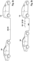
- the Figures 2a and 2b show representations of a vehicle 100 behind a foreign vehicle 110 when using a distance control cruise control and a distance controller according to an embodiment.
- the distance control cruise control and the distance controller are as in Fig. 1 implemented on a control unit of the vehicle 100.
- Fig. 2a the vehicle drives using the adaptive cruise control at the target distance 200 behind the other vehicle 110.
- the adaptive cruise control has essentially adjusted the speed of the vehicle 100 to the speed of the other vehicle by regulating the drive power provided.
- a current distance 202 is kept constant at an approximately constant speed within a tolerance range around the target distance 200.
- the vehicle 100 drives at a smaller distance 202 to the other vehicle 110 using the distance controller.
- the driver has exceeded the adaptive cruise control by stepping on the accelerator pedal and deflecting the accelerator pedal by a greater angle than corresponds to a power setpoint currently provided by the adaptive cruise control.
- the control unit then switched from the adaptive cruise control to the adaptive cruise control.
- the accelerator pedal angle is converted into the power setpoint until the distance 202 is within the buffer range 204 around the distance target value 130. Within the buffer range 204, the accelerator pedal angle is converted with increasing damping. In other words, the power setpoint is reduced even though the accelerator pedal angle remains the same.
- the power setpoint is reduced to such an extent that the vehicle 100 maintains the distance target value 130 from the other vehicle 110.
- the power setpoint is further reduced and the braking system of the vehicle 100 is activated as needed.
- the preselected distance target value 130 feels too far away from the other vehicle 110 to the driver, he can reduce the distance target value 130 by operating the accelerator pedal.
- the distance target value can be reduced to such an extent that the vehicle 100 only maintains a speed-dependent safety distance 206 from the other vehicle 110.
Landscapes
- Engineering & Computer Science (AREA)
- Automation & Control Theory (AREA)
- Transportation (AREA)
- Mechanical Engineering (AREA)
- Human Computer Interaction (AREA)
- Physics & Mathematics (AREA)
- Mathematical Physics (AREA)
- Control Of Driving Devices And Active Controlling Of Vehicle (AREA)
- Controls For Constant Speed Travelling (AREA)
- Control Of Vehicle Engines Or Engines For Specific Uses (AREA)
- Regulating Braking Force (AREA)
Description
- Die Erfindung betrifft ein Verfahren zum Betreiben eines Fahrzeugs und ein Steuergerät für ein Fahrzeug.
- Bei einem Fahrzeug mit einem Abstandsregeltempomat wird eine Motorleistung so geregelt, dass eine eingestellte Sollgeschwindigkeit eingehalten wird. Zusätzlich wird die Motorleistung so geregelt, dass ein situationsabhängiger Sollabstand zu einem vorausfahrenden Fahrzeug eingehalten wird. Wenn ein Fahrer des Fahrzeugs den Abstandsregeltempomat durch ein Betätigen eines Fahrpedals des Fahrzeugs übertritt, wird die Motorleistung entsprechend einer Winkelstellung des Fahrpedals erhöht. Wenn der Fahrer auf ein Bremspedal des Fahrzeugs tritt, wird der Abstandsregeltempomat deaktiviert.
-
US 2004/195022 A1 beschreibt ein Antriebssteuergerät für ein Fahrzeug.DE 10 2007 031543 A1 beschreibt ein Verfahren zur Sollabstandsvorgabe bei einer Geschwindigkeitsregelung auf einen vorgegebenen Sollabstand.JP 2010 143323 A - Vor diesem Hintergrund werden mit dem hier vorgestellten Ansatz ein Verfahren zum Betreiben eines Fahrzeugs und ein Steuergerät für ein Fahrzeug, sowie schließlich ein entsprechendes Computerprogrammprodukt und ein maschinenlesbares Speichermedium gemäß den unabhängigen Ansprüchen vorgestellt. Vorteilhafte Weiterbildungen und Verbesserungen des hier vorgestellten Ansatzes ergeben sich aus der Beschreibung und sind in den abhängigen Ansprüchen beschrieben.
- Ausführungsformen der vorliegenden Erfindung können in vorteilhafter Weise ermöglichen, ein Auffahren auf ein vorausfahrendes Fahrzeug auch beim Übertreten eines Abstandsregeltempomaten eines Fahrzeugs zu verhindern.
- Es wird ein Verfahren zum Betreiben eines Fahrzeugs vorgeschlagen, wobei bei aktiviertem Abstandsregeltempomat ansprechend auf einen durch ein Übertreten eines Fahrpedals des Fahrzeugs angezeigten Beschleunigungswunsch eines Fahrers des Fahrzeugs auf einen fahrpedalgesteuerten Abstandsregler gewechselt wird, wobei der Abstandsregeltempomat einen Leistungssollwert für einen Antrieb des Fahrzeugs in Abhängigkeit von einer aktuellen Geschwindigkeit des Fahrzeugs und in Abhängigkeit von einem aktuellen Abstand zu einem vorausfahrenden Fahrzeug derart regelt, dass der Abstand innerhalb eines Abstandstoleranzbereichs bleibt, wenn der Abstand im Wesentlichen einem geschwindigkeitsabhängigen Sollabstand entspricht, wobei der Abstandsregler den Beschleunigungswunsch in Abhängigkeit von dem aktuellen Abstand in den Leistungssollwert umsetzt, wobei eine Änderung des Leistungssollwerts umso geringer wird, je näher der aktuelle Abstand an einem Abstandszielwert ist, wobei der Abstandszielwert geringer als der Sollabstand ist, dadurch gekennzeichnet, dass ansprechend auf ein Ende des Beschleunigungswunschs von dem fahrpedalgesteuerten Abstandsregler zurück zur Verwendung des Abstandsregeltempomaten gewechselt wird, sodass das Fahrzeug wieder mit dem Sollabstand zum Fremdfahrzeug fährt, sobald der Fahrer den Fuß vom Fahrpedal nimmt.
- Ideen zu Ausführungsformen der vorliegenden Erfindung können unter anderem als auf den nachfolgend beschriebenen Gedanken und Erkenntnissen beruhend angesehen werden.
- Unter einem Abstandsregeltempomat kann ein Regler in einem Steuergerät eines Fahrzeugs verstanden werden, der einen Leistungssollwert für einen Antrieb des Fahrzeugs in Abhängigkeit von einer aktuellen Geschwindigkeit des Fahrzeugs und in Abhängigkeit von einem aktuellen Abstand zu einem vorausfahrenden Fahrzeug regelt. Das vorausfahrende Fahrzeug kann als Fremdfahrzeug bezeichnet werden.
- Der Leistungssollwert wird von dem Abstandsregeltempomat geregelt, bis die aktuelle Geschwindigkeit eine eingestellte Sollgeschwindigkeit erreicht. Entspricht die Geschwindigkeit im Wesentlichen der Sollgeschwindigkeit, regelt der Abstandsregeltempomat den Leistungssollwert so, dass die Geschwindigkeit innerhalb eines eingestellten Geschwindigkeitstoleranzbereichs um die Sollgeschwindigkeit bleibt. Ist die Geschwindigkeit geringer als die Sollgeschwindigkeit, wird der Leistungssollwert erhöht. Ist die Geschwindigkeit größer als die Sollgeschwindigkeit, wird der Leistungssollwert verringert. Die Geschwindigkeit wird innerhalb des Geschwindigkeitstoleranzbereichs gehalten, so lange der aktuelle Abstand zu einem vorausfahrenden Fahrzeug größer als ein vorgegebener, geschwindigkeitsabhängiger Sollabstand ist. Entspricht der Abstand im Wesentlichen dem Sollabstand, wird der Leistungssollwert von dem Abstandstempomat geregelt, sodass der Abstand innerhalb eines Abstandstoleranzbereichs bleibt. Ist der Abstand größer als der Sollabstand, wird der Leistungssollwert erhöht. Ist der Abstand kleiner als der Sollabstand, wird der Leistungssollwert verringert. Verkleinert sich der Abstand schneller, als durch den reduzierten Leistungssollwert ausgeglichen werden kann, wird ein Bremssystem des Fahrzeugs aktiviert, um den Abstand wieder auf den Sollabstand zu vergrößern. Der Abstand kann durch einen geschwindigkeitsunabhängigen Zeitschlitz ausgedrückt werden, da eine pro Zeiteinheit zurückgelegte Strecke abhängig von der Geschwindigkeit ist.
- Ein Beschleunigungswunsch eines Fahrers des Fahrzeugs wird über ein Fahrpedal des Fahrzeugs erfasst. Dabei wird ein Übertreten des Fahrpedals erkannt, wenn beispielsweise ein aktueller Winkel des Fahrpedals größer als ein Winkel ist, der dem momentan durch den Abstandsregeltempomat eingestellten Leistungssollwert entspricht.
- Ein fahrpedalgesteuerter Abstandsregler kann ein Regler in dem Steuergerät sein. Der Abstandsregler setzt den Beschleunigungswunsch in Abhängigkeit von dem aktuellen Abstand in den Leistungssollwert um. Eine Änderung des Beschleunigungswunschs wird dabei abhängig von dem aktuellen Abstand in eine Änderung des Leistungssollwerts umgesetzt. Je näher der aktuelle Abstand an einem Abstandszielwert ist, umso geringer wird die Änderung des Leistungssollwerts. Wenn das Fremdfahrzeug abbremst und der Abstandszielwert dadurch nicht eingehalten wird, wird der Beschleunigungswunsch reduziert und bei Bedarf wird ein Bremssystem des Fahrzeugs angesteuert, um das Fahrzeug ebenfalls abzubremsen.
- Ebenfalls kann der Leistungssollwert bei Annäherung an ein Fremdfahrzeug ohne Änderung des Beschleunigungswunschs (Beschleunigungswunsch = 0) reduziert werden, um den Abstandszielwert einzuhalten. (Beispiel: Ego-Fzg fährt mit 150 km/h oder beschleunigt und nähert sich mit konstantem Fahrpedalwinkel einem Fzg, das 120 km/h fährt). Der Abstandszielwert ist geringer als der Sollabstand.
- Ansprechend auf ein Ende des Beschleunigungswunschs wird von dem fahrpedalgesteuerten Abstandsregelmodus wieder zurück zur Verwendung des Abstandsregeltempomaten gewechselt. Dadurch fährt das Fahrzeug wieder dem Sollabstand zum Fremdfahrzeug, beziehungsweise kann das Fahrzeug wieder mit der Sollgeschwindigkeit fahren, sobald der Fahrer den Fuß vom Fahrpedal nimmt.
- Ansprechend auf eine Verzögerungsanforderung durch ein Betätigen eines Bremspedals des Fahrzeugs kann auf den fahrpedalgesteuerten Abstandsregler gewechselt werden. Dadurch wird der Abstand nach dem Bremsvorgang weiter überwacht und bei einer Verringerung des Abstands hin zum Abstandszielwert oder unter den Abstandszielwert wird der Beschleunigungswunsch reduziert und bei Bedarf wird automatisch abgebremst, um einen minimalen Abstand zu bewahren.
- Im fahrpedalgesteuerten Abstandsregelmodus kann der Abstandszielwert zu dem vorausfahrenden Fahrzeug in Abhängigkeit von dem Beschleunigungswunsch eingestellt werden. Der Abstandszielwert kann in Zeitschlitzen eingestellt werden. Der kleinste Abstandszielwert entspricht einem minimalen Sicherheitsabstand. Je größer der Beschleunigungswunsch ist, umso kleiner kann der Abstandszielwert eingestellt werden. Für Überholvorgänge kann ein kleinerer Abstand eingestellt werden, als für eine konstante Folgefahrt auf der Autobahn.
- Das Verfahren kann beispielsweise in Software oder Hardware oder in einer Mischform aus Software und Hardware beispielsweise in einem Steuergerät implementiert sein.
- Der hier vorgestellte Ansatz schafft ferner ein Steuergerät für ein Fahrzeug, das dazu ausgebildet ist, die Schritte einer Variante des hier vorgestellten Verfahrens in entsprechenden Einrichtungen durchzuführen, anzusteuern bzw. umzusetzen.
- Das Steuergerät kann ein elektrisches Gerät mit zumindest einer Recheneinheit zum Verarbeiten von Signalen oder Daten, zumindest einer Speichereinheit zum Speichern von Signalen oder Daten, und zumindest einer Schnittstelle und/oder einer Kommunikationsschnittstelle zum Einlesen oder Ausgeben von Daten, die in ein Kommunikationsprotokoll eingebettet sind, sein. Die Recheneinheit kann beispielsweise ein Signalprozessor, ein sogenannter System-ASIC oder ein Mikrocontroller zum Verarbeiten von Sensorsignalen und Ausgeben von Datensignalen in Abhängigkeit von den Sensorsignalen sein. Die Speichereinheit kann beispielsweise ein Flash-Speicher, ein EPROM oder eine magnetische Speichereinheit sein. Die Schnittstelle kann als Sensorschnittstelle zum Einlesen der Sensorsignale von einem Sensor und/oder als Aktorschnittstelle zum Ausgeben der Datensignale und/oder Steuersignale an einen Aktor ausgebildet sein. Die Kommunikationsschnittstelle kann dazu ausgebildet sein, die Daten drahtlos und/oder leitungsgebunden einzulesen oder auszugeben. Die Schnittstellen können auch Softwaremodule sein, die beispielsweise auf einem Mikrocontroller neben anderen Softwaremodulen vorhanden sind.
- Von Vorteil ist auch ein Computerprogrammprodukt oder Computerprogramm mit Programmcode, der auf einem maschinenlesbaren Träger oder Speichermedium wie einem Halbleiterspeicher, einem Festplattenspeicher oder einem optischen Speicher gespeichert sein kann und zur Durchführung, Umsetzung und/oder Ansteuerung der Schritte des Verfahrens nach einer der vorstehend beschriebenen Ausführungsformen verwendet wird, insbesondere wenn das Programmprodukt oder Programm auf einem Computer oder einer Vorrichtung ausgeführt wird.
- Es wird darauf hingewiesen, dass einige der möglichen Merkmale und Vorteile der Erfindung hierin mit Bezug auf unterschiedliche Ausführungsformen beschrieben sind. Ein Fachmann erkennt, dass die Merkmale des Steuergeräts und des Verfahrens in geeigneter Weise kombiniert, angepasst oder ausgetauscht werden können, um zu weiteren Ausführungsformen der Erfindung zu gelangen.
- Nachfolgend werden Ausführungsformen der Erfindung unter Bezugnahme auf die beigefügten Zeichnungen beschrieben, wobei weder die Zeichnungen noch die Beschreibung als die Erfindung einschränkend auszulegen sind.
-
Fig. 1 zeigt eine Darstellung eines Fahrzeugs mit einem Steuergerät gemäß einem Ausführungsbeispiel; und - die
Figuren 2a und 2b zeigen Darstellungen eines Fahrzeugs hinter einem Fremdfahrzeug bei der Verwendung eines Abstandsregeltempomaten und eines fahrpedalgesteuerten Abstandsreglers gemäß einem Ausführungsbeispiel. - Die Figuren sind lediglich schematisch und nicht maßstabsgetreu. Gleiche Bezugszeichen bezeichnen in den Figuren gleiche oder gleichwirkende Merkmale.
- Aktuell gibt es in Fahrzeugen unterschiedliche Fahrerassistenzfunktionen. Unter anderem dienen Cruise Control (CrCtl), Longitudinal Limiter (LLim), Advanced Longitudinal Limiter (ALLim) und Adaptive Cruise Control (ACC) dem Fahrer für einen erhöhten Komfort und mehr Sicherheit. Darüber hinaus leisten weitere Assistenzfunktionen einen Sicherheitsgewinn durch Abstandswarnungen und Notbremseingriffe.
- Die ACC-Funktionalität ist in bestimmten Situationen vorsichtiger ausgelegt als manche Fahrer selbst fahren würden. In diesen Situationen hat der Fahrer die Möglichkeit, bei einem herkömmlichen System per Fahrpedal mehr Moment anzufordern als die ACC-Funktion. Dies führt allerdings dazu, dass die herkömmliche ACC-Funktion inaktiv ist (Override-Status) und auf vorausfahrende Objekte nicht bremst. Beispielsweise kann bei einem Überholmanöver auf der Autobahn ein Übertreten per Fahrpedal dazu führen, dass ein Bremsen des zu überholenden Fahrzeugs nicht berücksichtigt wird und das eigene Fahrzeug daher nicht bremst.
- Bei dem hier vorgestellten Ansatz wird die bestehende ACC - Funktion um einen Auffahrschutz (Dynamic Distance/Drive Assist, DDA) mit einem dynamisch dem Fahrerwunsch angepassten Abstands- und / oder Geschwindigkeitspuffer ergänzt.
- Bei dem hier vorgestellten Ansatz wird die DDA-Funktion im Falle des Übertretens verwendet. So hat der Fahrer die Möglichkeit, zu beschleunigen, wird jedoch bei einem Bremsvorgang des zu überholenden Fahrzeugs durch das Einhalten eines gewünschten Abstands noch geschützt. Die DDA kann dabei auf eine geringe Zeitlücke eingestellt sein oder fortlaufend den Soll-Abstand auf Fahrpedalwunsch anpassen. Letzteres führt dazu, dass der Fahrer bei einer gewünschten Beschleunigung per Fahrpedal kaum/nicht eingeschränkt wird, wohl aber bei einem Bremsvorgang des vorausfahrenden Fahrzeugs gebremst bzw. geschützt wird.
-
Fig. 1 zeigt eine Darstellung eines Fahrzeugs 100 mit einem Steuergerät 102 gemäß einem Ausführungsbeispiel. Im Steuergerät 102 sind ein Abstandsregeltempomat 104 und ein Abstandsregler 106 implementiert. Das Steuergerät 102 kann weitere, hier nicht beschriebene Funktionen aufweisen. - Der Abstandsregeltempomat 104 ist ein Regler für einen Leistungssollwert 108 des Fahrzeugs 100. Der Leistungssollwert 108 repräsentiert eine von einem Antrieb des Fahrzeugs 100 abzugebende Leistung. Wenn der Abstandsregeltempomat 104 aktiv ist, regelt er die abgegebene Leistung in Abhängigkeit von einer aktuellen Geschwindigkeit des Fahrzeugs 100 und eines aktuellen Abstands zwischen dem Fahrzeug und einem vorausfahrenden Fahrzeug 110.
- Der Abstandsregeltempomat 104 liest dazu einen Geschwindigkeitswert 112 und einen Abstandswert 114 ein. Der Geschwindigkeitswert 112 repräsentiert die aktuelle Geschwindigkeit. Der Abstandswert 114 repräsentiert den aktuellen Abstand zu dem vorausfahrenden Fahrzeug 110. Der aktuelle Abstand wird durch einen Abstandssensor 116 des Fahrzeugs 100 gemessen.
- Der Abstandsregeltempomat 104 liest ferner einen Sollgeschwindigkeitswert 118 und einen Sollabstandswert 120 ein. Der Sollgeschwindigkeitswert 118 repräsentiert eine Sollgeschwindigkeit des Fahrzeugs und wird von einem Fahrer des Fahrzeugs 100 über eine Schnittstelle 122 eingestellt. Der Sollabstandswert 120 repräsentiert einen Sollabstand zu dem vorausfahrenden Fahrzeug 114. Der Sollabstandswert 120 wird ebenso von dem Fahrer über die Schnittstelle 122 oder eine hier nicht dargestellte weitere Schnittstelle eingestellt.
- Der Sollabstand ist geschwindigkeitsabhängig. Bei größerer Geschwindigkeit ist der Sollabstand größer, als bei kleinerer Geschwindigkeit. Daher kann der Sollabstandswert 120 als Zeitlücke eingelesen werden, die geschwindigkeitsunabhängig ist. Die Zeitlücke beschreibt eine Zeitdauer, bis das Fahrzeug 100 den gleichen Punkt überfährt, wie zuvor das vorausfahrende Fahrzeug 110.
- Der Abstandsregeltempomat 104 erhöht den Leistungssollwert 108, wenn die Geschwindigkeit des Fahrzeugs 100 geringer als die Sollgeschwindigkeit ist. Umgekehrt wird der Leistungssollwert 108 verringert, wenn die Geschwindigkeit größer als die Sollgeschwindigkeit ist. Zusätzlich wird der Leistungssollwert 108 verringert, wenn der Abstand kleiner als der Sollabstand ist. Dadurch sinkt die Geschwindigkeit. Solange die Geschwindigkeit kleiner als die Sollgeschwindigkeit ist, wird der Leistungssollwert 108 erhöht, wenn der Abstand größer als der Sollabstand ist.
- Wenn der Abstand kleiner als der Sollabstand wird, beispielsweise weil das vorausfahrende Fahrzeug 110 bremst, gibt der Abstandsregeltempomat 104 einen Bremssollwert 124 für ein Bremssystem des Fahrzeugs 100 aus, um das Fahrzeug 100 abzubremsen, bis der Abstand wieder mit dem Sollabstand übereinstimmt.
- Der Abstandsregler 106 ist ebenfalls ein Regler für den Leistungssollwert 108. Wenn der Abstandsregler 106 aktiv ist, regelt er die abgegebene Leistung in Abhängigkeit von dem Abstand und einem Beschleunigungswunsch des Fahrers. Der Beschleunigungswunsch wird durch einen Fahrpedalwinkel 126 eines Fahrpedals 128 des Fahrzeugs 100 repräsentiert. Der Beschleunigungswunsch wird unter Verwendung des Abstands in den Leistungssollwert 108 umgesetzt.
- Dazu liest der Abstandsregler 106 einen Abstandszielwert 130 ein. Der Abstandszielwert 130 repräsentiert einen Mindestabstand, der von dem Fahrer an der Schnittstelle 122 oder einer anderen nicht dargestellten Schnittstelle vorgegeben wird.
- Der Mindestabstand ist geschwindigkeitsabhängig. Bei größerer Geschwindigkeit ist der Mindestabstand größer, als bei kleinerer Geschwindigkeit. Daher kann der Abstandszielwert 130 ebenfalls als Zeitlücke eingelesen werden, die geschwindigkeitsunabhängig ist. Der Mindestabstand kann kleiner sein, als der Sollabstand.
- So lange der aktuelle Abstand außerhalb eines Pufferbereichs vor dem Mindestabstand ist, wird der Beschleunigungswunsch direkt in den Leistungssollwert 108 umgesetzt. Liegt der Abstand innerhalb des Pufferbereichs, wird der Beschleunigungswunsch in reduzierter Form in den Leistungssollwert 108 umgesetzt. Je näher der Abstand am Mindestabstand liegt, umso weniger wird der Beschleunigungswunsch in den Leistungssollwert 108 umgesetzt. Entspricht der Abstand dem Mindestabstand, regelt der Abstandsregler 106 den Leistungssollwert 108 so, dass der Mindestabstand nicht unterschritten wird.
- Wenn eine Reduktion des Leistungssollwert 108 nicht ausreicht, um den Abstandszielwert 130 zu erreichen, gibt der Abstandsregler 106 den Bremssollwert 124 für das Bremssystem des Fahrzeugs 100 aus, um das Fahrzeug 100 abzubremsen, bis der Abstand wieder mit dem Mindestabstand übereinstimmt.
- In einem Ausführungsbeispiel kann der Fahrer den Mindestabstand beeinflussen. Wenn der Fahrer den Fahrpedalwinkel 126 erhöht, sodass er oberhalb eines Schwellwerts liegt, oder / und mit einer Winkelgeschwindigkeit verändert, die oberhalb eines Schwellenwerts liegt, wird die mit dem eingestellten Abstandszielwert 130 korrespondierende Zeitlücke verkleinert. Insbesondere wird die Zeitlücke schrittweise verkleinert. Die Zeitlücke kann minimal so klein werden, wie eine gesamte Reaktionszeit des Systems.
- Wenn der Fahrer über das Fahrpedal 128 wieder einen reduzierten Beschleunigungswunsch signalisiert, wird die Zeitlücke wieder vergrößert.
- Bei dem hier vorgestellten Ansatz wird von dem Abstandsregeltempomat 104 auf den Abstandsregler 106 gewechselt, wenn der Fahrer über das Fahrpedal 128 einen Beschleunigungswunsch einstellt, der einem größeren Leistungssollwert 108 entspricht, als der aktuell vom Abstandsregeltempomat 104 ausgegebene Leistungssollwert 108. So kann der Fahrer den Abstandsregeltempomat 104 übertreten und das Fahrzeug über die Sollgeschwindigkeit hinaus beschleunigen. Der erforderliche Abstand zum vorausfahrenden Fahrzeug 110 wird dennoch weiter überwacht und im Notfall durch einen Bremseingriff erhalten.
- Wenn der Beschleunigungswunsch wieder einem geringeren Leistungssollwert 108 entspricht, als der der aktuell vom Abstandsregeltempomat 104 ausgegebene Leistungssollwert 108, wird von dem Abstandsregler 106 wieder auf den Abstandsregeltempomat 104 gewechselt.
- In einem Ausführungsbeispiel wird von dem Abstandsregeltempomat 104 auf den Abstandsregler 106 gewechselt, wenn der Fahrer ein Bremspedal des Fahrzeugs 100 betätigt. Dadurch bleibt die Überwachung des Abstands zum vorausfahrenden Fahrzeug 110 erhalten und das Fahrzeug 100 wird bereits beim Unterschreiten des eingestellten Abstandszielwerts 130 sanft gebremst, bevor ein eventuell vorhandener Notbremsassistent einen harten Bremseingriff ausführen wird.
- Die
Figuren 2a und 2b zeigen Darstellungen eines Fahrzeugs 100 hinter einem Fremdfahrzeug 110 bei der Verwendung eines Abstandsregeltempomaten und eines Abstandsreglers gemäß einem Ausführungsbeispiel. Der Abstandsregeltempomat und der Abstandsregler sind wie inFig. 1 auf einem Steuergerät des Fahrzeugs 100 implementiert. - In
Fig. 2a fährt das Fahrzeug unter Verwendung des Abstandsregeltempomaten mit dem Sollabstand 200 hinter dem Fremdfahrzeug 110. Der Abstandsregeltempomat hat die Geschwindigkeit des Fahrzeugs 100 durch regelnde Eingriffe in die bereitgestellte Antriebsleistung im Wesentlichen an die Geschwindigkeit des Fremdfahrzeugs angepasst. Ein aktueller Abstand 202 wird bei näherungsweise konstanter Geschwindigkeit innerhalb eines Toleranzbereichs um den Sollabstand 200 konstant gehalten. - In
Fig. 2b fährt das Fahrzeug 100 unter Verwendung des Abstandsreglers mit einem geringeren Abstand 202 zu dem Fremdfahrzeug 110. Der Fahrer hat den Abstandsregeltempomaten übertreten, indem er auf das Fahrpedal getreten ist und das Fahrpedal um einen größeren Fahrpedalwinkel ausgelenkt hat, als einem momentan von dem Abstandsregeltempomaten bereitgestellten Leistungssollwert entspricht. Daraufhin hat das Steuergerät von dem Abstandsregeltempomaten auf den Abstandsregler gewechselt. - Im Abstandsregelbetrieb wird der Fahrpedalwinkel in den Leistungssollwert umgesetzt, bis der Abstand 202 innerhalb des Pufferbereichs 204 um den Abstandszielwert 130 liegt. Innerhalb des Pufferbereichs 204 wird der Fahrpedalwinkel zunehmend gedämpft umgesetzt. Mit anderen Worten wird der Leistungssollwert reduziert, obwohl der Fahrpedalwinkel gleich bleibt.
- Wenn der Abstand 202 dem Abstandszielwert 130 entspricht, wird der Leistungssollwert soweit reduziert, dass das Fahrzeug 100 den Abstandszielwert 130 zu dem Fremdfahrzeug 110 hält.
- Wenn das Fremdfahrzeug 110 in der Situation langsamer wird oder bremst, wird der Leistungssollwert weiter reduziert und nach Bedarf das Bremssystem des Fahrzeugs 100 aktiviert.
- Wenn der vorgewählte Abstandszielwert 130 für den Fahrer gefühlt zu weit entfernt von dem Fremdfahrzeug 110 ist, dann kann er den Abstandszielwert 130 durch eine Fahrpedalbetätigung verringern. Der Abstandszielwert kann dabei soweit verringert werden, dass das Fahrzeug 100 nur noch einen geschwindigkeitsabhängigen Sicherheitsabstand 206 zum Fremdfahrzeug 110 einhält.
- Abschließend ist darauf hinzuweisen, dass Begriffe wie "aufweisend", "umfassend", etc. keine anderen Elemente oder Schritte ausschließen und Begriffe wie "eine" oder "ein" keine Vielzahl ausschließen. Bezugszeichen in den Ansprüchen sind nicht als Einschränkung anzusehen.
Claims (6)
- Verfahren zum Betreiben eines Fahrzeugs (100), wobei bei aktiviertem Abstandsregeltempomat (104) ansprechend auf einen durch ein Übertreten eines Fahrpedals (128) des Fahrzeugs (100) angezeigten Beschleunigungswunsch eines Fahrers des Fahrzeugs auf einen fahrpedalgesteuerten Abstandsregler (106) gewechselt wird,wobei der Abstandsregeltempomat (104) einen Leistungssollwert (108) für einen Antrieb des Fahrzeugs (100) in Abhängigkeit von einer aktuellen Geschwindigkeit des Fahrzeugs (100) und in Abhängigkeit von einem aktuellen Abstand (202) zu einem vorausfahrenden Fahrzeug (110) derart regelt, dass der Abstand (202) innerhalb eines Abstandstoleranzbereichs bleibt, wenn der Abstand (202) im Wesentlichen einem geschwindigkeitsabhängigen Sollabstand (200) entspricht,wobei der Abstandsregler (106) den Beschleunigungswunsch in Abhängigkeit von dem aktuellen Abstand (202) in den Leistungssollwert (108) umsetzt,wobei eine Änderung des Leistungssollwerts (108) umso geringer wird, je näher der aktuelle Abstand (202) an einem Abstandszielwert (130) ist,wobei der Abstandszielwert (130) geringer als der Sollabstand (200) ist, dadurch gekennzeichnet, dass ansprechend auf ein Ende des Beschleunigungswunschs von dem fahrpedalgesteuerten Abstandsregler (106) zurück zur Verwendung des Abstandsregeltempomaten (104) gewechselt wird, [sodass das Fahrzeug (100) wieder mit dem Sollabstand (200) zum Fremdfahrzeug (110) fährt, sobald der Fahrer den Fuß vom Fahrpedal (128) nimmt.
- Verfahren gemäß einem der vorhergehenden Ansprüche, bei dem ansprechend auf eine Verzögerungsanforderung durch ein Betätigen eines Bremspedals des Fahrzeugs (100) ebenfalls auf den fahrpedalgesteuerten Abstandsregler (106) gewechselt wird.
- Verfahren gemäß einem der vorhergehenden Ansprüche, bei dem während der Verwendung des fahrpedalgesteuerten Abstandsreglers (105) ein Abstandszielwert (130) zu einem vorausfahrenden Fahrzeug (110) in Abhängigkeit von dem Beschleunigungswunsch eingestellt wird.
- Steuergerät (102) für ein Fahrzeug, wobei das Steuergerät (102) dazu ausgebildet ist, das Verfahren gemäß einem der vorhergehenden Ansprüche in entsprechenden Einrichtungen auszuführen, umzusetzen und/oder anzusteuern.
- Computerprogrammprodukt, umfassend Befehle, die bei der Ausführung des Programms durch einen Computer diesen veranlassen, das Verfahren gemäß einem der Ansprüche 1-3 auszuführen.
- Maschinenlesbares Speichermedium, auf dem das Computerprogrammprodukt gemäß Anspruch 5 gespeichert ist.
Applications Claiming Priority (3)
| Application Number | Priority Date | Filing Date | Title |
|---|---|---|---|
| DE102018210074 | 2018-06-21 | ||
| DE102018212296.2A DE102018212296A1 (de) | 2018-06-21 | 2018-07-24 | Verfahren zum Betreiben eines Fahrzeugs und Steuergerät |
| PCT/EP2019/060832 WO2019242914A1 (de) | 2018-06-21 | 2019-04-27 | Verfahren zum betreiben eines fahrzeugs und steuergerät |
Publications (2)
| Publication Number | Publication Date |
|---|---|
| EP3810472A1 EP3810472A1 (de) | 2021-04-28 |
| EP3810472B1 true EP3810472B1 (de) | 2025-01-01 |
Family
ID=68805952
Family Applications (1)
| Application Number | Title | Priority Date | Filing Date |
|---|---|---|---|
| EP19724747.1A Active EP3810472B1 (de) | 2018-06-21 | 2019-04-27 | Verfahren zum betreiben eines fahrzeugs und steuergerät |
Country Status (7)
| Country | Link |
|---|---|
| US (1) | US11420626B2 (de) |
| EP (1) | EP3810472B1 (de) |
| JP (1) | JP2021528309A (de) |
| KR (1) | KR102795005B1 (de) |
| CN (1) | CN112292299B (de) |
| DE (1) | DE102018212296A1 (de) |
| WO (1) | WO2019242914A1 (de) |
Families Citing this family (7)
| Publication number | Priority date | Publication date | Assignee | Title |
|---|---|---|---|---|
| DE102018221860A1 (de) * | 2018-12-17 | 2020-07-02 | Volkswagen Aktiengesellschaft | Verfahren und Assistenzsystem zur Vorbereitung und/oder Durchführung eines Spurwechsels |
| JP7122295B2 (ja) * | 2019-09-30 | 2022-08-19 | 本田技研工業株式会社 | 車両制御装置 |
| DE102019130201A1 (de) * | 2019-11-08 | 2021-05-12 | WABCO Global GmbH | Verfahren zum Steuern eines Fahrzeuges sowie Abstandsregel- Steuereinrichtung |
| JP7287299B2 (ja) * | 2020-01-31 | 2023-06-06 | トヨタ自動車株式会社 | 車両および車両制御インターフェース |
| JP7306284B2 (ja) * | 2020-01-31 | 2023-07-11 | トヨタ自動車株式会社 | 車両および車両制御インターフェース |
| DE102020115309A1 (de) * | 2020-06-09 | 2021-12-09 | Bayerische Motoren Werke Aktiengesellschaft | Fahrerassistenz im Niedriggeschwindigkeitsbereich |
| DE102024120777A1 (de) * | 2024-07-22 | 2026-01-22 | Bayerische Motoren Werke Aktiengesellschaft | Fahrassistenzsystem und Fahrassistenzverfahren für ein Fahrzeug |
Citations (9)
| Publication number | Priority date | Publication date | Assignee | Title |
|---|---|---|---|---|
| JPH10318009A (ja) | 1997-05-16 | 1998-12-02 | Mitsubishi Electric Corp | 車両用追従走行制御装置 |
| DE19859284A1 (de) | 1998-12-22 | 2000-06-29 | Bosch Gmbh Robert | Verfahren und Vorrichtung zur Geschwindigkeits- und Abstandsregelung eines Kraftfahrzeuges |
| US20040195022A1 (en) | 2003-04-03 | 2004-10-07 | Honda Motor Co., Ltd. | Drive control apparatus for vehicle |
| DE102005036924A1 (de) | 2005-08-05 | 2007-02-08 | Bayerische Motoren Werke Ag | Fahrerassistenzsystem für ein Kraftfahrzeug |
| DE102007031543A1 (de) | 2007-07-06 | 2009-01-08 | Bayerische Motoren Werke Aktiengesellschaft | Verfahren zur Sollabstandsvorgabe bei einer Geschwindigkeitsregelung auf einen vorgegebenen Sollabstand |
| US20100070151A1 (en) | 2008-09-17 | 2010-03-18 | Hitachi Automotive Systems, Ltd. | Vehicle Speed Control Device and Method for Controlling Vehicle Speed |
| JP2010143323A (ja) | 2008-12-17 | 2010-07-01 | Toyota Motor Corp | 車間距離制御装置 |
| JP2011016496A (ja) | 2009-07-10 | 2011-01-27 | Nissan Motor Co Ltd | 先行車追従制御装置および先行車追従制御方法 |
| DE102011121041A1 (de) | 2010-12-22 | 2012-08-23 | Bendix Commercial Vehicle Systems, Llc | Anti-Auffahr-System und Anti-Auffahr-Verfahren |
Family Cites Families (17)
| Publication number | Priority date | Publication date | Assignee | Title |
|---|---|---|---|---|
| JP3358509B2 (ja) * | 1997-09-10 | 2002-12-24 | 日産自動車株式会社 | 車両用走行制御装置 |
| JP2002087110A (ja) * | 2000-09-20 | 2002-03-26 | Nissan Motor Co Ltd | 車両用追従走行制御装置 |
| JP4066609B2 (ja) * | 2001-03-19 | 2008-03-26 | 日産自動車株式会社 | 車両用走行制御装置の状態表示装置 |
| JP3987044B2 (ja) * | 2004-02-19 | 2007-10-03 | 本田技研工業株式会社 | 車間距離制御装置 |
| JP4176690B2 (ja) * | 2004-09-03 | 2008-11-05 | 本田技研工業株式会社 | 車両の走行制御装置 |
| JP4451315B2 (ja) * | 2005-01-06 | 2010-04-14 | 富士重工業株式会社 | 車両の運転支援装置 |
| WO2010116499A1 (ja) * | 2009-04-08 | 2010-10-14 | トヨタ自動車株式会社 | 車両走行制御装置 |
| CN101648522B (zh) * | 2009-08-31 | 2013-07-03 | 冯大钧 | 车辆自动巡航的控制方法及电子节气门系统 |
| JP2012187979A (ja) * | 2011-03-09 | 2012-10-04 | Nissan Motor Co Ltd | 車間距離制御装置及び車間距離制御方法 |
| JP5927717B2 (ja) * | 2012-03-30 | 2016-06-01 | 本田技研工業株式会社 | 走行制御装置 |
| GB2505027B (en) * | 2012-08-16 | 2015-03-04 | Jaguar Land Rover Ltd | Vehicle speed control system |
| US9050982B2 (en) * | 2013-01-11 | 2015-06-09 | Ford Global Technologies, Llc | Driver feedback for vehicle operation |
| CN104627180B (zh) * | 2014-12-19 | 2018-05-04 | 北京新能源汽车股份有限公司 | 一种半主动巡航控制系统及其方法 |
| KR101704221B1 (ko) * | 2015-06-24 | 2017-02-07 | 현대자동차주식회사 | 차량 주행 제어 방법 |
| JP6406141B2 (ja) * | 2015-06-30 | 2018-10-17 | トヨタ自動車株式会社 | 車両走行制御装置 |
| JP6706196B2 (ja) * | 2016-12-26 | 2020-06-03 | 株式会社デンソー | 走行制御装置 |
| DE102020204081A1 (de) * | 2019-11-14 | 2021-05-20 | Robert Bosch Gesellschaft mit beschränkter Haftung | Verfahren zum Betreiben eines fahrpedalgesteuerten Abstandsreglers eines Fahrzeugs und Steuergerät |
-
2018
- 2018-07-24 DE DE102018212296.2A patent/DE102018212296A1/de not_active Withdrawn
-
2019
- 2019-04-27 US US16/772,752 patent/US11420626B2/en active Active
- 2019-04-27 CN CN201980041667.7A patent/CN112292299B/zh active Active
- 2019-04-27 EP EP19724747.1A patent/EP3810472B1/de active Active
- 2019-04-27 WO PCT/EP2019/060832 patent/WO2019242914A1/de not_active Ceased
- 2019-04-27 KR KR1020217001683A patent/KR102795005B1/ko active Active
- 2019-04-27 JP JP2020570934A patent/JP2021528309A/ja active Pending
Patent Citations (9)
| Publication number | Priority date | Publication date | Assignee | Title |
|---|---|---|---|---|
| JPH10318009A (ja) | 1997-05-16 | 1998-12-02 | Mitsubishi Electric Corp | 車両用追従走行制御装置 |
| DE19859284A1 (de) | 1998-12-22 | 2000-06-29 | Bosch Gmbh Robert | Verfahren und Vorrichtung zur Geschwindigkeits- und Abstandsregelung eines Kraftfahrzeuges |
| US20040195022A1 (en) | 2003-04-03 | 2004-10-07 | Honda Motor Co., Ltd. | Drive control apparatus for vehicle |
| DE102005036924A1 (de) | 2005-08-05 | 2007-02-08 | Bayerische Motoren Werke Ag | Fahrerassistenzsystem für ein Kraftfahrzeug |
| DE102007031543A1 (de) | 2007-07-06 | 2009-01-08 | Bayerische Motoren Werke Aktiengesellschaft | Verfahren zur Sollabstandsvorgabe bei einer Geschwindigkeitsregelung auf einen vorgegebenen Sollabstand |
| US20100070151A1 (en) | 2008-09-17 | 2010-03-18 | Hitachi Automotive Systems, Ltd. | Vehicle Speed Control Device and Method for Controlling Vehicle Speed |
| JP2010143323A (ja) | 2008-12-17 | 2010-07-01 | Toyota Motor Corp | 車間距離制御装置 |
| JP2011016496A (ja) | 2009-07-10 | 2011-01-27 | Nissan Motor Co Ltd | 先行車追従制御装置および先行車追従制御方法 |
| DE102011121041A1 (de) | 2010-12-22 | 2012-08-23 | Bendix Commercial Vehicle Systems, Llc | Anti-Auffahr-System und Anti-Auffahr-Verfahren |
Also Published As
| Publication number | Publication date |
|---|---|
| JP2021528309A (ja) | 2021-10-21 |
| KR102795005B1 (ko) | 2025-04-15 |
| KR20210022679A (ko) | 2021-03-03 |
| US20210162999A1 (en) | 2021-06-03 |
| CN112292299B (zh) | 2024-11-29 |
| EP3810472A1 (de) | 2021-04-28 |
| DE102018212296A1 (de) | 2019-12-24 |
| CN112292299A (zh) | 2021-01-29 |
| WO2019242914A1 (de) | 2019-12-26 |
| US11420626B2 (en) | 2022-08-23 |
Similar Documents
| Publication | Publication Date | Title |
|---|---|---|
| EP3810472B1 (de) | Verfahren zum betreiben eines fahrzeugs und steuergerät | |
| DE112019003322B4 (de) | Fahrzeugsteuervorrichtung | |
| EP3365212B1 (de) | Verfahren und vorrichtung zum steuern eines warnmoduls | |
| EP1412930B1 (de) | Verfahren und vorrichtung zum selbsttätigen auslösen einer verzögerung eines fahrzeugs | |
| DE112009004643B4 (de) | Fahrzeugfahrsteuervorrichtung | |
| DE102018201306A1 (de) | Verfahren und Abstandsregler zum Regeln eines Abstands eines Fahrzeugs zu einem vorausfahrenden Fahrzeug | |
| DE102012212616A1 (de) | Verfahren zur Verbesserung der Fahrstabilität | |
| DE112009004706T5 (de) | Fahrassistenzvorrichtung | |
| WO2005054008A1 (de) | Verfahren und vorrichtung zur warnung des fahrers eines kraftfahrzeugs | |
| DE102013205641A1 (de) | Automatische Geschwindigkeitsregelung im Gefälle für Fahrzeuge | |
| DE10015299A1 (de) | Verfahren und Vorrichtung zur Auslösung einer Übernahmeaufforderung für ACC-gesteuerte Fahrzeuge | |
| WO2004007231A1 (de) | Verfahren und vorrichtung zur benachrichtigung des fahrers eines kraftfahrzeugs | |
| DE102008023100A1 (de) | Steuervorrichtung und -verfahren für den Fahrzeugzwischenabstand | |
| EP1276630A1 (de) | Verfahren und vorrichtung zur einstellung der fahrzeuglängsgeschwindigkeit auf eine sollgeschwindigkeit | |
| EP3007952A1 (de) | Verfahren und vorrichtung zum betreiben eines fahrzeugs | |
| EP1575799B1 (de) | Vorrichtung zur adaptiven abstands- und geschwindigkeitsregelung mit ruckbegrenzung | |
| EP4338998B1 (de) | Verfahren und fahrerassistenzsystem zum betreiben eines zweirads | |
| WO2004005092A1 (de) | Fahrerassistenzsystem und vorrichtung zur bremsenregelung | |
| DE102020204081A1 (de) | Verfahren zum Betreiben eines fahrpedalgesteuerten Abstandsreglers eines Fahrzeugs und Steuergerät | |
| DE102014211496B4 (de) | Fahrerassistenzsystem zur Längsdynamikregelung | |
| DE102018211440A1 (de) | Verfahren und Steuergerät zum Betreiben eines Fahrerassistenzsystems eines Fahrzeugs | |
| WO2018029052A1 (de) | Verfahren zur koordination von fahrerassistenzfunktionen | |
| EP4288314A1 (de) | Verfahren und system zur längssteuerung eines kraftfahrzeugs | |
| EP1764277B1 (de) | Verfahren und Vorrichtung zur Geschwindigkeitsregelung eines Kraftfahrzeuges | |
| EP4341142B1 (de) | Verfahren und vorrichtung zur ermittlung einer beschleunigungsvorgabe für ein fahrzeug |
Legal Events
| Date | Code | Title | Description |
|---|---|---|---|
| STAA | Information on the status of an ep patent application or granted ep patent |
Free format text: STATUS: UNKNOWN |
|
| STAA | Information on the status of an ep patent application or granted ep patent |
Free format text: STATUS: THE INTERNATIONAL PUBLICATION HAS BEEN MADE |
|
| PUAI | Public reference made under article 153(3) epc to a published international application that has entered the european phase |
Free format text: ORIGINAL CODE: 0009012 |
|
| STAA | Information on the status of an ep patent application or granted ep patent |
Free format text: STATUS: REQUEST FOR EXAMINATION WAS MADE |
|
| 17P | Request for examination filed |
Effective date: 20210121 |
|
| AK | Designated contracting states |
Kind code of ref document: A1 Designated state(s): AL AT BE BG CH CY CZ DE DK EE ES FI FR GB GR HR HU IE IS IT LI LT LU LV MC MK MT NL NO PL PT RO RS SE SI SK SM TR |
|
| AX | Request for extension of the european patent |
Extension state: BA ME |
|
| DAV | Request for validation of the european patent (deleted) | ||
| DAX | Request for extension of the european patent (deleted) | ||
| STAA | Information on the status of an ep patent application or granted ep patent |
Free format text: STATUS: EXAMINATION IS IN PROGRESS |
|
| 17Q | First examination report despatched |
Effective date: 20230411 |
|
| GRAP | Despatch of communication of intention to grant a patent |
Free format text: ORIGINAL CODE: EPIDOSNIGR1 |
|
| STAA | Information on the status of an ep patent application or granted ep patent |
Free format text: STATUS: GRANT OF PATENT IS INTENDED |
|
| RIC1 | Information provided on ipc code assigned before grant |
Ipc: B60W 50/00 20060101ALI20241010BHEP Ipc: B60W 30/16 20200101AFI20241010BHEP |
|
| INTG | Intention to grant announced |
Effective date: 20241022 |
|
| GRAS | Grant fee paid |
Free format text: ORIGINAL CODE: EPIDOSNIGR3 |
|
| GRAA | (expected) grant |
Free format text: ORIGINAL CODE: 0009210 |
|
| STAA | Information on the status of an ep patent application or granted ep patent |
Free format text: STATUS: THE PATENT HAS BEEN GRANTED |
|
| AK | Designated contracting states |
Kind code of ref document: B1 Designated state(s): AL AT BE BG CH CY CZ DE DK EE ES FI FR GB GR HR HU IE IS IT LI LT LU LV MC MK MT NL NO PL PT RO RS SE SI SK SM TR |
|
| REG | Reference to a national code |
Ref country code: GB Ref legal event code: FG4D Free format text: NOT ENGLISH |
|
| REG | Reference to a national code |
Ref country code: CH Ref legal event code: EP |
|
| REG | Reference to a national code |
Ref country code: DE Ref legal event code: R096 Ref document number: 502019012740 Country of ref document: DE |
|
| REG | Reference to a national code |
Ref country code: IE Ref legal event code: FG4D Free format text: LANGUAGE OF EP DOCUMENT: GERMAN |
|
| REG | Reference to a national code |
Ref country code: LT Ref legal event code: MG9D |
|
| REG | Reference to a national code |
Ref country code: NL Ref legal event code: MP Effective date: 20250101 |
|
| PG25 | Lapsed in a contracting state [announced via postgrant information from national office to epo] |
Ref country code: NL Free format text: LAPSE BECAUSE OF FAILURE TO SUBMIT A TRANSLATION OF THE DESCRIPTION OR TO PAY THE FEE WITHIN THE PRESCRIBED TIME-LIMIT Effective date: 20250101 |
|
| PG25 | Lapsed in a contracting state [announced via postgrant information from national office to epo] |
Ref country code: FI Free format text: LAPSE BECAUSE OF FAILURE TO SUBMIT A TRANSLATION OF THE DESCRIPTION OR TO PAY THE FEE WITHIN THE PRESCRIBED TIME-LIMIT Effective date: 20250101 |
|
| PG25 | Lapsed in a contracting state [announced via postgrant information from national office to epo] |
Ref country code: PL Free format text: LAPSE BECAUSE OF FAILURE TO SUBMIT A TRANSLATION OF THE DESCRIPTION OR TO PAY THE FEE WITHIN THE PRESCRIBED TIME-LIMIT Effective date: 20250101 |
|
| PGFP | Annual fee paid to national office [announced via postgrant information from national office to epo] |
Ref country code: DE Payment date: 20250624 Year of fee payment: 7 |
|
| PG25 | Lapsed in a contracting state [announced via postgrant information from national office to epo] |
Ref country code: ES Free format text: LAPSE BECAUSE OF FAILURE TO SUBMIT A TRANSLATION OF THE DESCRIPTION OR TO PAY THE FEE WITHIN THE PRESCRIBED TIME-LIMIT Effective date: 20250101 |
|
| PGFP | Annual fee paid to national office [announced via postgrant information from national office to epo] |
Ref country code: GB Payment date: 20250423 Year of fee payment: 7 |
|
| PG25 | Lapsed in a contracting state [announced via postgrant information from national office to epo] |
Ref country code: NO Free format text: LAPSE BECAUSE OF FAILURE TO SUBMIT A TRANSLATION OF THE DESCRIPTION OR TO PAY THE FEE WITHIN THE PRESCRIBED TIME-LIMIT Effective date: 20250401 Ref country code: IS Free format text: LAPSE BECAUSE OF FAILURE TO SUBMIT A TRANSLATION OF THE DESCRIPTION OR TO PAY THE FEE WITHIN THE PRESCRIBED TIME-LIMIT Effective date: 20250501 |
|
| PG25 | Lapsed in a contracting state [announced via postgrant information from national office to epo] |
Ref country code: HR Free format text: LAPSE BECAUSE OF FAILURE TO SUBMIT A TRANSLATION OF THE DESCRIPTION OR TO PAY THE FEE WITHIN THE PRESCRIBED TIME-LIMIT Effective date: 20250101 |
|
| PG25 | Lapsed in a contracting state [announced via postgrant information from national office to epo] |
Ref country code: PT Free format text: LAPSE BECAUSE OF FAILURE TO SUBMIT A TRANSLATION OF THE DESCRIPTION OR TO PAY THE FEE WITHIN THE PRESCRIBED TIME-LIMIT Effective date: 20250502 Ref country code: LV Free format text: LAPSE BECAUSE OF FAILURE TO SUBMIT A TRANSLATION OF THE DESCRIPTION OR TO PAY THE FEE WITHIN THE PRESCRIBED TIME-LIMIT Effective date: 20250101 |
|
| PGFP | Annual fee paid to national office [announced via postgrant information from national office to epo] |
Ref country code: FR Payment date: 20250422 Year of fee payment: 7 |
|
| PG25 | Lapsed in a contracting state [announced via postgrant information from national office to epo] |
Ref country code: GR Free format text: LAPSE BECAUSE OF FAILURE TO SUBMIT A TRANSLATION OF THE DESCRIPTION OR TO PAY THE FEE WITHIN THE PRESCRIBED TIME-LIMIT Effective date: 20250402 Ref country code: BG Free format text: LAPSE BECAUSE OF FAILURE TO SUBMIT A TRANSLATION OF THE DESCRIPTION OR TO PAY THE FEE WITHIN THE PRESCRIBED TIME-LIMIT Effective date: 20250101 |
|
| PG25 | Lapsed in a contracting state [announced via postgrant information from national office to epo] |
Ref country code: CZ Free format text: LAPSE BECAUSE OF FAILURE TO SUBMIT A TRANSLATION OF THE DESCRIPTION OR TO PAY THE FEE WITHIN THE PRESCRIBED TIME-LIMIT Effective date: 20250101 |
|
| PG25 | Lapsed in a contracting state [announced via postgrant information from national office to epo] |
Ref country code: SE Free format text: LAPSE BECAUSE OF FAILURE TO SUBMIT A TRANSLATION OF THE DESCRIPTION OR TO PAY THE FEE WITHIN THE PRESCRIBED TIME-LIMIT Effective date: 20250101 |
|
| REG | Reference to a national code |
Ref country code: DE Ref legal event code: R026 Ref document number: 502019012740 Country of ref document: DE |
|
| PG25 | Lapsed in a contracting state [announced via postgrant information from national office to epo] |
Ref country code: SM Free format text: LAPSE BECAUSE OF FAILURE TO SUBMIT A TRANSLATION OF THE DESCRIPTION OR TO PAY THE FEE WITHIN THE PRESCRIBED TIME-LIMIT Effective date: 20250101 |
|
| PG25 | Lapsed in a contracting state [announced via postgrant information from national office to epo] |
Ref country code: DK Free format text: LAPSE BECAUSE OF FAILURE TO SUBMIT A TRANSLATION OF THE DESCRIPTION OR TO PAY THE FEE WITHIN THE PRESCRIBED TIME-LIMIT Effective date: 20250101 |
|
| PLBI | Opposition filed |
Free format text: ORIGINAL CODE: 0009260 |
|
| PLAX | Notice of opposition and request to file observation + time limit sent |
Free format text: ORIGINAL CODE: EPIDOSNOBS2 |
|
| PG25 | Lapsed in a contracting state [announced via postgrant information from national office to epo] |
Ref country code: IT Free format text: LAPSE BECAUSE OF FAILURE TO SUBMIT A TRANSLATION OF THE DESCRIPTION OR TO PAY THE FEE WITHIN THE PRESCRIBED TIME-LIMIT Effective date: 20250101 |
|
| REG | Reference to a national code |
Ref country code: CH Ref legal event code: L10 Free format text: ST27 STATUS EVENT CODE: U-0-0-L10-L00 (AS PROVIDED BY THE NATIONAL OFFICE) Effective date: 20251015 |
|
| PG25 | Lapsed in a contracting state [announced via postgrant information from national office to epo] |
Ref country code: EE Free format text: LAPSE BECAUSE OF FAILURE TO SUBMIT A TRANSLATION OF THE DESCRIPTION OR TO PAY THE FEE WITHIN THE PRESCRIBED TIME-LIMIT Effective date: 20250101 |
|
| PG25 | Lapsed in a contracting state [announced via postgrant information from national office to epo] |
Ref country code: RO Free format text: LAPSE BECAUSE OF FAILURE TO SUBMIT A TRANSLATION OF THE DESCRIPTION OR TO PAY THE FEE WITHIN THE PRESCRIBED TIME-LIMIT Effective date: 20250101 |
|
| PG25 | Lapsed in a contracting state [announced via postgrant information from national office to epo] |
Ref country code: SK Free format text: LAPSE BECAUSE OF FAILURE TO SUBMIT A TRANSLATION OF THE DESCRIPTION OR TO PAY THE FEE WITHIN THE PRESCRIBED TIME-LIMIT Effective date: 20250101 |
|
| 26 | Opposition filed |
Opponent name: ZF CV SYSTEMS GLOBAL GMBH Effective date: 20251001 |
|
| REG | Reference to a national code |
Ref country code: CH Ref legal event code: H13 Free format text: ST27 STATUS EVENT CODE: U-0-0-H10-H13 (AS PROVIDED BY THE NATIONAL OFFICE) Effective date: 20251125 |
|
| PG25 | Lapsed in a contracting state [announced via postgrant information from national office to epo] |
Ref country code: LU Free format text: LAPSE BECAUSE OF NON-PAYMENT OF DUE FEES Effective date: 20250427 |
|
| PG25 | Lapsed in a contracting state [announced via postgrant information from national office to epo] |
Ref country code: MC Free format text: LAPSE BECAUSE OF FAILURE TO SUBMIT A TRANSLATION OF THE DESCRIPTION OR TO PAY THE FEE WITHIN THE PRESCRIBED TIME-LIMIT Effective date: 20250101 |
|
| REG | Reference to a national code |
Ref country code: BE Ref legal event code: MM Effective date: 20250430 |
|
| PG25 | Lapsed in a contracting state [announced via postgrant information from national office to epo] |
Ref country code: BE Free format text: LAPSE BECAUSE OF NON-PAYMENT OF DUE FEES Effective date: 20250430 |
|
| PG25 | Lapsed in a contracting state [announced via postgrant information from national office to epo] |
Ref country code: CH Free format text: LAPSE BECAUSE OF NON-PAYMENT OF DUE FEES Effective date: 20250430 |
|
| PLBB | Reply of patent proprietor to notice(s) of opposition received |
Free format text: ORIGINAL CODE: EPIDOSNOBS3 |