EP3803003B1 - Serrure de porte de véhicule à moteur - Google Patents
Serrure de porte de véhicule à moteur Download PDFInfo
- Publication number
- EP3803003B1 EP3803003B1 EP19731137.6A EP19731137A EP3803003B1 EP 3803003 B1 EP3803003 B1 EP 3803003B1 EP 19731137 A EP19731137 A EP 19731137A EP 3803003 B1 EP3803003 B1 EP 3803003B1
- Authority
- EP
- European Patent Office
- Prior art keywords
- pawl
- drive
- lever
- locking mechanism
- vehicle door
- Prior art date
- Legal status (The legal status is an assumption and is not a legal conclusion. Google has not performed a legal analysis and makes no representation as to the accuracy of the status listed.)
- Active
Links
Images




Classifications
-
- E—FIXED CONSTRUCTIONS
- E05—LOCKS; KEYS; WINDOW OR DOOR FITTINGS; SAFES
- E05B—LOCKS; ACCESSORIES THEREFOR; HANDCUFFS
- E05B85/00—Details of vehicle locks not provided for in groups E05B77/00 - E05B83/00
- E05B85/20—Bolts or detents
- E05B85/24—Bolts rotating about an axis
- E05B85/26—Cooperation between bolts and detents
-
- E—FIXED CONSTRUCTIONS
- E05—LOCKS; KEYS; WINDOW OR DOOR FITTINGS; SAFES
- E05B—LOCKS; ACCESSORIES THEREFOR; HANDCUFFS
- E05B77/00—Vehicle locks characterised by special functions or purposes
- E05B77/36—Noise prevention; Anti-rattling means
-
- E—FIXED CONSTRUCTIONS
- E05—LOCKS; KEYS; WINDOW OR DOOR FITTINGS; SAFES
- E05B—LOCKS; ACCESSORIES THEREFOR; HANDCUFFS
- E05B81/00—Power-actuated vehicle locks
- E05B81/02—Power-actuated vehicle locks characterised by the type of actuators used
- E05B81/04—Electrical
-
- E—FIXED CONSTRUCTIONS
- E05—LOCKS; KEYS; WINDOW OR DOOR FITTINGS; SAFES
- E05B—LOCKS; ACCESSORIES THEREFOR; HANDCUFFS
- E05B81/00—Power-actuated vehicle locks
- E05B81/02—Power-actuated vehicle locks characterised by the type of actuators used
- E05B81/04—Electrical
- E05B81/06—Electrical using rotary motors
-
- E—FIXED CONSTRUCTIONS
- E05—LOCKS; KEYS; WINDOW OR DOOR FITTINGS; SAFES
- E05B—LOCKS; ACCESSORIES THEREFOR; HANDCUFFS
- E05B81/00—Power-actuated vehicle locks
- E05B81/12—Power-actuated vehicle locks characterised by the function or purpose of the powered actuators
- E05B81/14—Power-actuated vehicle locks characterised by the function or purpose of the powered actuators operating on bolt detents, e.g. for unlatching the bolt
-
- E—FIXED CONSTRUCTIONS
- E05—LOCKS; KEYS; WINDOW OR DOOR FITTINGS; SAFES
- E05B—LOCKS; ACCESSORIES THEREFOR; HANDCUFFS
- E05B81/00—Power-actuated vehicle locks
- E05B81/12—Power-actuated vehicle locks characterised by the function or purpose of the powered actuators
- E05B81/20—Power-actuated vehicle locks characterised by the function or purpose of the powered actuators for assisting final closing or for initiating opening
-
- E—FIXED CONSTRUCTIONS
- E05—LOCKS; KEYS; WINDOW OR DOOR FITTINGS; SAFES
- E05B—LOCKS; ACCESSORIES THEREFOR; HANDCUFFS
- E05B81/00—Power-actuated vehicle locks
- E05B81/12—Power-actuated vehicle locks characterised by the function or purpose of the powered actuators
- E05B81/20—Power-actuated vehicle locks characterised by the function or purpose of the powered actuators for assisting final closing or for initiating opening
- E05B81/21—Power-actuated vehicle locks characterised by the function or purpose of the powered actuators for assisting final closing or for initiating opening with means preventing or detecting pinching of objects or body parts
Definitions
- the invention relates to a motor vehicle door lock, with a locking mechanism consisting of a rotary latch and at least one pawl, and also with a closing drive and an opening drive for the locking mechanism, with the rotary latch being able to be transferred to an overtravel position with the aid of the closing drive, with the rotary latch being used to open the locking mechanism is held in the overtravel position with the help of the closing drive, so that the opening drive opens the pawl and the closing drive can then move back when the locking mechanism is open, with an additional internal actuating lever and/or an external actuating lever being provided for mechanical loading of the locking mechanism, with the opening drive working on a release lever .
- Motor vehicle door locks with a locking mechanism consisting of a rotary latch and at least one pawl, which are also equipped with an opening drive for the locking mechanism are often referred to in practice as so-called electric locks.
- the locking mechanism is usually opened purely electrically, namely by the opening drive lifting the pawl from its engagement with the rotary latch.
- the rotary latch can pivot spring-assisted and release a previously caught locking bolt, as is the case in connection with a two-ratchet mechanism as part of the DE 10 2013 103 245 A1 the applicant is described in detail.
- the closing drive ensures that the locking mechanism is also closed with the help of an electric motor.
- the locking mechanism first assumes a pre-locking position, for example by an operator manually closing an associated motor vehicle door. Starting from this pre-locking position, the closing drive then ensures that the locking mechanism is transferred to the main locking position. In order for the pawl to fall securely into the associated main catch, the closing drive ensures that the locking mechanism or the rotary latch as a whole is transferred into an overtravel position beyond its main catch position.
- a combined motorized closing and opening aid is implemented.
- a first output element acts as a closing aid, while a second output element assumes the function of an opening aid. Since an associated output wheel acts on the first output element in one direction and on the second output element in an opposite direction, both functions can be implemented separately from one another.
- the EP 1 404 936 B1 deals with a lock, in particular for motor vehicle doors or flaps, which works in a comparable way.
- a first output element works in a first running direction of the drive as an opening aid on the pawl.
- a second output element acts in a second direction of travel of the drive part, opposite the first direction of travel, as a closing aid on the rotary latch.
- the invention is based on the technical problem of further developing such a motor vehicle door lock in such a way that the noise development, in particular when the locking mechanism is opened, is further reduced compared to previous embodiments.
- the invention proposes in a generic motor vehicle door lock that the closing drive has a drive pawl and a transmission lever, the drive pawl being rotatably connected to the transmission lever at one end and being able to interact with a pin of the rotary latch at the other end. wherein the drive pawl interacting with the release lever guide contour and one with the Internal actuating lever/external actuating lever has an interactive ejector contour.
- the invention is initially based on the finding that the overtravel position of the catch used to open the locking mechanism ensures with the help of the closing drive that all elements of an associated trigger chain are decoupled from opening forces built up by a rubber door seal. This means that the tripping chain in question can be transferred to the open position with virtually no force as a result of the assumed overtravel position of the rotary latch and consequently of the locking mechanism, and without this being associated with any disturbing noise development.
- the release lever ensures that the pawl is lifted from its latching position relative to the rotary latch, which position it assumed when the locking mechanism was in the closed state. Since, according to the invention, the rotary latch is held in the overtravel position to open the locking mechanism and first with the help of the closing drive, there is no longer any latching between the pawl and the rotary latch. The pawl can consequently be opened in the overtravel position of the rotary latch without canceling a latching effect with the aid of the opening drive or, in general, the release chain.
- the pawl held in the open position with the help of the opening drive now ensures that the closing drive can then move back when the locking mechanism is open.
- the invention is based on the further knowledge that when the closing drive is retracted, the rotary latch, starting from its overtravel position, moves into the open position (possibly spring-loaded) can pass. During this process, the pawl is still held in its open position with the help of the opening drive. Here, the rotary latch passes the pawl, which cannot fall into it and can then come to rest on the opened rotary latch.
- the opening drive can also return to its basic position, because the pawl is then held in contact with the rotary latch and, in the consequently assumed open position of the locking mechanism, cannot latch into the rotary latch.
- the opening drive works on the release lever already mentioned as a further component of the release chain.
- an inside actuating lever and/or an outside actuating lever is provided for mechanical loading of the locking mechanism.
- the inside actuating lever and/or the outside actuating lever are consequently added to the release chain and ensure that the locking mechanism in question is not only actuated by a motor, but can also be opened mechanically.
- the inside operating lever and/or the outside operating lever allow an additional and mechanical ejection. This generally means an interruption of a closing process and/or an electrical opening process.
- the inside actuating lever and/or the outside actuating lever usually work on a drive pawl as part of the closing drive and in this way interrupt the closing drive.
- an electrical opening process can be interrupted mechanically.
- the opening drive and the outside actuating lever and/or the inside actuating lever can act on a common stop edge of the release lever. Since the release lever in turn lifts the pawl from its engagement with the rotary latch, it has proven useful if the release lever is mounted on the same axis as the pawl. In this way, the release lever can advantageously interact with a pin of the pawl during an opening process of the locking mechanism.
- the closing drive has, among other things, a drive pawl and a transmission lever.
- one end of the drive pawl is rotatably connected to the transmission lever.
- the other end of the drive pawl interacts with a pin of the rotary latch.
- the design is also such that the drive pawl converts a motor-driven pivoting movement of the transmission lever into a pushing movement working on the pin of the rotary latch to pull the rotary latch closed.
- the drive pawl In order for the drive pawl to be guided towards the pin of the rotary latch and to be able to carry out the pushing movement mentioned, the drive pawl is guided according to the invention with the aid of a guide pin on the release lever.
- the guide pin in question on the release lever interacts with a guide contour on the drive pawl.
- the drive pawl is not only equipped with the already mentioned guide contour that interacts with the release lever, but also has an ejector contour.
- the ejector contour in turn interacts with the inside activation lever and/or outside activation lever.
- the interaction described occurs between the guide contour and the guide pin on the release lever or the release lever itself. This ensures that the drive pawl is guided towards the pin of the rotary latch during the closing process described and, after contacting the pin, applies the desired pushing movement to it.
- the guide contour can interact with the opening drive via the release lever.
- the guide contour and the ejector contour are generally spaced apart.
- the electrical travel range of the release lever corresponds to the fact that the release lever is loaded with the help of the opening drive to lift the pawl from the rotary latch to such an extent that the pin or guide pin on the release lever leaves the guide contour, but does not interact or cannot interact with the ejector contour.
- the release lever which is acted upon with the aid of the inside actuating lever and/or outside actuating lever, interacts with its guide pin with the ejector contour on the drive pawl.
- the drive pawl is ejected and any closing process is interrupted because this interrupts a mechanical connection from the closing drive via the drive pawl to the pin on the rotary latch.
- the drive pawl is generally designed as a frame pawl enclosing a cavity.
- the guide pin of the release lever can be moved in the cavity.
- the electrical movement range corresponds to the guide pin of the release lever leaving the guide contour and being moved into the interior of the cavity, but without being able to interact with the ejector contour of the drive pawl.
- generally inner longitudinal legs of the frame latch define on the one hand the guide contour and on the other hand the ejector contour, which consequently extend in opposite directions and essentially in the same direction.
- any closing process can be mechanically interrupted at any time. This is of particular importance if, for example, during the closing process in the closing door gap between a door leaf and the motor vehicle body, an operator's piece of clothing should be pinched or, in the worst case, even a finger. In any case, the closing process can be interrupted immediately by the operator interrupting the closing process or separating the mechanical connection via the inside actuating lever and/or outside actuating lever.
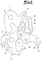
- a motor vehicle door lock is shown, which is reduced to the components and elements essential to the invention.
- two pawls 2, 3 are realized. It is therefore a non-limiting multi-ratchet ratchet 1, 2, 3.
- the first ratchet 2 is according to the terminology in the previously referred to DE 10 2013 103 245 A1 designed as a comfort latch 2.
- the second pawl 3 is a pre-ratchet pawl 3 (cf. in particular figure 4 ).
- the locking mechanism 1, 2, 3 in a main locking position and interacts with a locking bolt, not shown, which may be arranged on a motor vehicle body. Both pawls 2, 3 are rotatably and stationarily mounted in a lock case, not shown.
- the first pawl or comfort pawl 2 ensures that the rotary latch 1 is held in this position.
- the second pawl or pre-locking pawl 3 ensures that the comfort pawl 2 is not removed from its retracted position in a main locking position of the rotary latch 1 .
- the focus is mainly on the first pawl or comfort pawl 2 .
- an opening drive 4 works on a release lever 5, as in the figure 1 is indicated.
- the locking mechanism 1, 2, 3 can be opened mechanically and independently of the electromotive opening drive 4 independently of the electromotive opening drive 4 with the aid of an internal actuating lever or external actuating lever 6.
- an inside door handle or outside door handle which is not expressly shown, ensures that the inside actuating lever or outside actuating lever 6 acts on the release lever 5 in a direction comparable to that of the opening drive 4 (cf. figure 2 ).
- a corresponding loading of the release lever 5 in the opening direction in figure 1 indicated direction of the arrow means that a stop edge 7 on the release lever 5 to the right and in the front view after the figure 3 and the rear view of the figure 4 is moved up, like an associated arrow in the figure 3 and 4 implied.
- the opening movement of the release lever 5 causes the release lever 5 to move in the figure 3 shown pivoting movement clockwise around its axis 8 completes.
- the release lever 5 and the first pawl or comfort pawl 2 are mounted on the same axis, taking into account the common axis 8 in the lock housing, not shown in detail.
- a forth-going rotational movement of the release lever 5 in the leads figure 3 shown clockwise to the fact that in this process the first pawl or comfort pawl 2 is taken in the direction of clockwise movement.
- a connecting pin 9 which is connected to the first pawl or comfort pawl 2 in question and against which the release lever 5 at its described (clockwise) pivoting movement in the course of an opening process in the figure 3 moves.
- the first pawl or comfort pawl 2 is lifted off the rotary latch 1 .
- the first pawl 2 in question performs one in the rear view figure 4 Detectable and corresponding counterclockwise movement around the common axis 8 with the release lever 5.
- This releases the rotary latch 1 from the first pawl or comfort pawl 2, because at the same time the release lever 5 during this process the first latch 3 about its axis 10 in the figure 4 also indicated pivoted clockwise.
- the now free rotary latch 1 can result in spring-assisted in the figure 4 pivot counterclockwise around its axis 11, thereby releasing the previously caught locking bolt.
- the locking mechanism 1, 2, 3 is open.
- the motor vehicle door lock according to the invention is also equipped with a closing drive 12, 13, 14.
- the closing drive 12, 13, 14 has a drive pawl 14.
- a transmission lever 13 is also provided.
- the transmission lever 13 is mounted in a stationary and rotatable manner within the motor vehicle door lock or a motor vehicle housing, specifically about an axis 15.
- the drive pawl 14 is rotatably connected to the transmission lever 13 at one end.
- a further axis of rotation 16 is provided for this purpose. With its other end, the drive pawl 14 interacts with a pin 17 on the rotary latch 1 for closing the locking mechanism 1, 2, 3, as will be explained in more detail below.
- the drive pawl 14 converts a motor-induced pivoting movement of the transmission lever 13 into a thrust movement working on the pin 17 on the rotary latch 1, so that in this way the rotary latch 1 and thus the locking mechanism 1, 2, 3 as a whole can be closed.
- This can be seen in particular in the Figures 5A to 5C .
- a pivoting movement of the transmission lever 13 about the associated axis 15 in the Figure 5A indicated clockwise to the fact that the drive pawl 14 mounted on the transmission lever 13 is moved in the direction of the pin 17 on the rotary latch 1 .
- a drive or electric motor 12 works on the transmission lever 13, as is the case figure 3 shows. The movement is guided on the one hand by the axis 16 and on the other hand by a pin or guide pin 18 on the release lever 5 .
- the drive pawl 14 is designed as a frame pawl enclosing a cavity 19 .
- the associated longitudinal limbs define a guide contour 20 and an ejector contour 21 on the inside, the design and functioning of which will be explained in more detail below.
- a guided pushing movement of the transmission lever 14 is generated, with the help of which the drive pawl 14 works on the pin 17 on the rotary latch 1 and thereby the rotary latch 1 moves in the pinch direction as seen in the Figures 5A and 5B recognizes.
- the locking mechanism 1, 2, 3 shown in the pre-locked position.
- the drive pawl 14 remains unchanged as part of the closing drive 12, 13, 14 in contact with the pin 17 of the catch 1.
- the opening drive 4 can now open the pawl 2, 3.
- the pawl 2 is released from the spaced rotary latch 1 with the aid of the release lever 5 in accordance with the Figure 5C indicated clockwise movement lifted.
- the closing drive 12, 13, 14 can now be driven back with the locking mechanism open.
- the opening drive 4 acts on the pawl or the first pawl 2 unchanged in the opening sense.
- the closing drive 12, 13, 14 can return to its starting position.
- the rotary latch 1 is opened. Now can too the opening drive 4 for the pawl 2 can be moved back to its starting position. This is because the rotary latch 1 in the open position ensures that the pawl 2 cannot fall into a latching position, but rather rests against the open rotary latch 1 .
Landscapes
- Lock And Its Accessories (AREA)
Claims (10)
- Serrure de porte de véhicule automobile, comprenant un mécanisme de verrouillage (1, 2, 3) composé d'un loquet rotatif (1) et d'au moins un cliquet d'arrêt (2, 3), comprenant en outre un entraînement de fermeture (12, 13, 14) et un entraînement d'ouverture (4) pour le mécanisme de verrouillage (1, 2, 3), le loquet rotatif (1) pouvant être déplacé à l'aide de l'entraînement de fermeture (12, 13, 14) jusqu'à une position de surcourse,pour l'ouverture du mécanisme de verrouillage (1, 2, 3) le loquet rotatif (1) étant maintenu dans la position de surcourse à l'aide de l'entraînement de fermeture (12, 13, 14), de sorte que l'entraînement d'ouverture (4) ouvre le cliquet d'arrêt (2, 3) et ensuite l'entraînement de fermeture (12, 13, 14) puisse revenir en arrière lorsque le mécanisme de verrouillage (1, 2, 3) est ouvert, un levier d'actionnement interne et/ou un levier d'actionnement externe (6) pour la sollicitation mécanique du mécanisme de verrouillage (1, 2, 3) étant en outre prévu, l'entraînement d'ouverture (4) agissant sur un levier de déclenchement (5),caractérisée en ce quel'entraînement de fermeture (12, 13, 14) présente un cliquet d'entraînement (14) et un levier de transmission (13), le cliquet d'entraînement (14) étant raccordé par son extrémité de manière rotative au levier de transmission (13) et pouvant coopérer avec son autre extrémité avec un tourillon (17) du loquet rotatif (1),le cliquet d'entraînement (14) présentant un contour de guidage (20) coopérant avec le levier de déclenchement (5) et un contour éjecteur (21) coopérant avec le levier d'actionnement interne/levier d'actionnement externe (6).
- Serrure de porte de véhicule automobile selon la revendication 1, caractérisée en ce que l'entraînement d'ouverture (4) revient à sa position initiale en cas de mécanisme de verrouillage (1, 2, 3) ouvert.
- Serrure de porte de véhicule automobile selon l'une des revendications 1 à 2, caractérisée en ce que l'entraînement d'ouverture (4) ainsi que le levier d'actionnement externe/levier d'actionnement interne (6) entrent en prise avec un bord de butée (7) commun du levier de déclenchement (5).
- Serrure de porte de véhicule automobile selon l'une des revendications 1 à 3, caractérisée en ce que le levier de déclenchement (5) est monté de manière coaxiale au cliquet d'arrêt (2).
- Serrure de porte de véhicule automobile selon l'une des revendications 1 à 4, caractérisée en ce que le levier de déclenchement (5) coopère avec un tourillon (9) du cliquet d'arrêt (2) lors d'un processus d'ouverture du mécanisme de verrouillage (1, 2, 3).
- Serrure de porte de véhicule automobile selon la revendication 1, caractérisée en ce que le cliquet d'entraînement (14) transforme un mouvement de pivotement du levier de transmission (13) provoqué par moteur en un mouvement de poussée travaillant sur le tourillon (17) du loquet rotatif (1) pour la fermeture du loquet rotatif (1).
- Serrure de porte de véhicule automobile selon la revendication 1, caractérisée en ce que le contour de guidage (20) coopère avec un tourillon de guidage (18) sur le levier de déclenchement (5).
- Serrure de porte de véhicule automobile selon la revendication 1, caractérisée en ce que le contour éjecteur (21) coopère par l'intermédiaire du levier de déclenchement (5) avec le levier d'actionnement interne/levier d'actionnement externe (6).
- Serrure de porte de véhicule automobile selon la revendication 1, caractérisée en ce que le contour de guidage (20) et le contour éjecteur (21) sont espacés l'un de l'autre, de sorte qu'une zone de déplacement motorisé et une zone de déplacement manuel du levier de déclenchement (5) puissent être différenciées.
- Serrure de porte de véhicule automobile selon la revendication 1, caractérisée en ce que le cliquet d'entraînement (14) est conçu comme un cliquet de cadre, entourant un espace creux (19) comportant le tourillon de guidage (18), pouvant s'y déplacer, du levier de déclenchement (5), dont les branches longitudinales côté interne définissent le contour de guidage (20) et le contour éjecteur (21).
Applications Claiming Priority (2)
| Application Number | Priority Date | Filing Date | Title |
|---|---|---|---|
| DE102018113270.0A DE102018113270A1 (de) | 2018-06-05 | 2018-06-05 | Kraftfahrzeugtürschloss |
| PCT/DE2019/100479 WO2019233524A1 (fr) | 2018-06-05 | 2019-05-31 | Serrure de porte de véhicule à moteur |
Publications (2)
| Publication Number | Publication Date |
|---|---|
| EP3803003A1 EP3803003A1 (fr) | 2021-04-14 |
| EP3803003B1 true EP3803003B1 (fr) | 2023-06-21 |
Family
ID=66912496
Family Applications (1)
| Application Number | Title | Priority Date | Filing Date |
|---|---|---|---|
| EP19731137.6A Active EP3803003B1 (fr) | 2018-06-05 | 2019-05-31 | Serrure de porte de véhicule à moteur |
Country Status (4)
| Country | Link |
|---|---|
| US (1) | US11933091B2 (fr) |
| EP (1) | EP3803003B1 (fr) |
| DE (1) | DE102018113270A1 (fr) |
| WO (1) | WO2019233524A1 (fr) |
Cited By (1)
| Publication number | Priority date | Publication date | Assignee | Title |
|---|---|---|---|---|
| WO2025228474A1 (fr) * | 2024-05-02 | 2025-11-06 | Kiekert Aktiengesellschaft | Procédé et dispositif d'ouverture d'un élément de porte d'un véhicule automobile |
Families Citing this family (13)
| Publication number | Priority date | Publication date | Assignee | Title |
|---|---|---|---|---|
| US11359418B2 (en) * | 2018-07-19 | 2022-06-14 | Brose Schliesssysteme Gmbh & Co. Kg | Motor vehicle lock |
| US11619078B2 (en) | 2018-07-19 | 2023-04-04 | Brose Schliesssysteme Gmbh & Co. Kommanditgesellschaft | Motor vehicle lock |
| JP7215153B2 (ja) * | 2018-12-26 | 2023-01-31 | 株式会社アイシン | 車両用ドアロック装置 |
| CN216866322U (zh) * | 2020-08-05 | 2022-07-01 | 恩坦华产品有限公司 | 侧门闩锁 |
| DE102020215931A1 (de) * | 2020-12-15 | 2022-06-15 | Witte Automotive Gmbh | Schließvorrichtung |
| US11821241B2 (en) * | 2021-06-01 | 2023-11-21 | AISIN Technical Center of America, Inc. | System and method for operating a power tailgate system |
| CN113494218B (zh) * | 2021-07-26 | 2022-08-16 | 上海恩井汽车科技有限公司 | 锁装置及机动车 |
| USD1003686S1 (en) * | 2021-11-04 | 2023-11-07 | Marine Town Inc. | Latch |
| DE102022107656A1 (de) | 2022-03-31 | 2023-10-05 | Kiekert Aktiengesellschaft | Kraftfahrzeug-Schloss, insbesondere Kraftfahrzeug-Türschloss |
| DE102023106833A1 (de) * | 2023-03-20 | 2024-09-26 | Audi Aktiengesellschaft | Verriegelungseinrichtung für eine Heckklappe eines Kraftfahrzeugs |
| DE102023122231A1 (de) * | 2023-08-21 | 2025-02-27 | Kiekert Aktiengesellschaft | Zuzieheinrichtung für ein Kraftfahrzeug-Schloss |
| DE102024102857A1 (de) * | 2024-02-01 | 2025-08-07 | Kiekert Aktiengesellschaft | Kraftfahrzeug-Schloss |
| DE102024210018A1 (de) * | 2024-10-16 | 2026-04-16 | Witte Automotive Gmbh | Verriegelungsvorrichtung und Fahrzeugelement |
Family Cites Families (15)
| Publication number | Priority date | Publication date | Assignee | Title |
|---|---|---|---|---|
| DE19919765A1 (de) | 1999-04-29 | 2000-11-09 | Bosch Gmbh Robert | Kraftfahrzeug-Türschloß o.dgl. mit elektrischer Öffnungshilfe und Schließhilfe |
| DE10133092A1 (de) | 2001-07-11 | 2003-01-30 | Huf Huelsbeck & Fuerst Gmbh | Schloß, insbesondere für Kraftfahrzeugtüren, -klappen od. dgl. |
| US6659515B2 (en) * | 2001-10-30 | 2003-12-09 | Kiekert Ag | Power-closing motor-vehicle door latch |
| DE10327997A1 (de) * | 2003-06-21 | 2005-01-13 | Huf Hülsbeck & Fürst Gmbh & Co. Kg | Schloss für Türen oder Klappen an Fahrzeugen |
| DE102004011798B3 (de) | 2004-03-11 | 2005-10-13 | Huf Hülsbeck & Fürst Gmbh & Co. Kg | Schloss, insbesondere für Fahrzeugtüren, -klappen oder dergleichen |
| DE102004034628A1 (de) | 2004-07-16 | 2006-02-16 | Brose Schließsysteme GmbH & Co.KG | Kraftfahrzeugschloß |
| DE102004044929A1 (de) * | 2004-09-14 | 2006-03-30 | Huf Hülsbeck & Fürst Gmbh & Co. Kg | Verschluss für bewegliche Karosserieteile eines Fahrzeugs, wie eine Heckklappe |
| DE102006035556A1 (de) | 2006-07-27 | 2008-01-31 | Huf Hülsbeck & Fürst Gmbh & Co. Kg | Verschluss für Fahrzeuge |
| EP2050903B1 (fr) | 2007-10-17 | 2012-06-27 | Huf Hülsbeck & Fürst GmbH & Co. KG | Fermeture pour véhicules |
| DE102007057560A1 (de) * | 2007-11-29 | 2009-06-04 | Huf Hülsbeck & Fürst Gmbh & Co. Kg | Verschluss für Fahrzeuge |
| DE102008035607A1 (de) * | 2008-07-31 | 2010-02-04 | Kiekert Ag | Schlosseinheit mit zwei Sperrklinken und Positionserkennungsmitteln |
| DE202008015789U1 (de) * | 2008-11-28 | 2010-04-22 | Kiekert Ag | Kraftfahrzeugtürverschluss |
| JP5919600B2 (ja) * | 2012-04-11 | 2016-05-18 | 三井金属アクト株式会社 | 車両用ラッチ装置 |
| DE102013103245A1 (de) | 2013-03-28 | 2014-10-02 | Kiekert Aktiengesellschaft | Kraftfahrzeugtürverschluss |
| KR102681036B1 (ko) * | 2016-12-19 | 2024-07-03 | 현대자동차주식회사 | 차량용 테일게이트의 개폐장치 |
-
2018
- 2018-06-05 DE DE102018113270.0A patent/DE102018113270A1/de not_active Withdrawn
-
2019
- 2019-05-31 EP EP19731137.6A patent/EP3803003B1/fr active Active
- 2019-05-31 US US15/734,585 patent/US11933091B2/en active Active
- 2019-05-31 WO PCT/DE2019/100479 patent/WO2019233524A1/fr not_active Ceased
Cited By (1)
| Publication number | Priority date | Publication date | Assignee | Title |
|---|---|---|---|---|
| WO2025228474A1 (fr) * | 2024-05-02 | 2025-11-06 | Kiekert Aktiengesellschaft | Procédé et dispositif d'ouverture d'un élément de porte d'un véhicule automobile |
Also Published As
| Publication number | Publication date |
|---|---|
| DE102018113270A1 (de) | 2019-12-05 |
| US11933091B2 (en) | 2024-03-19 |
| US20210230911A1 (en) | 2021-07-29 |
| EP3803003A1 (fr) | 2021-04-14 |
| WO2019233524A1 (fr) | 2019-12-12 |
Similar Documents
| Publication | Publication Date | Title |
|---|---|---|
| WO2019233524A1 (fr) | Serrure de porte de véhicule à moteur | |
| EP1288406B1 (fr) | Serrure de porte de véhicule automobile | |
| EP2925944B1 (fr) | Serrure de porte de véhicule automobile | |
| EP2715018B1 (fr) | Dispositif d'actionnement | |
| EP3697987A1 (fr) | Serrure de porte de véhicule à moteur | |
| DE102013103245A1 (de) | Kraftfahrzeugtürverschluss | |
| EP3956534B1 (fr) | Serrure de porte, en particulier serrure de porte de véhicule automobile | |
| DE10327448A1 (de) | Kraftfahrzeugtürverschluss | |
| DE102020108310A1 (de) | Haubenschloss - Zwangsmitnahme SPK durch DRF bei Doppelhub | |
| WO2024012616A1 (fr) | Serrure de véhicule à moteur, en particulier serrure de portière de véhicule à moteur | |
| WO2020260359A1 (fr) | Serrure de véhicule automobile | |
| WO2015032383A2 (fr) | Serrure de porte de véhicule à moteur | |
| DE202016104688U1 (de) | Kraftfahrzeugschloss | |
| DE102019135464A1 (de) | Kraftfahrzeug-Schloss | |
| WO2019048006A1 (fr) | Serrure de porte de véhicule automobile | |
| WO2025040214A1 (fr) | Dispositif de fermeture pour serrure de véhicule automobile | |
| DE19738265C2 (de) | Einrichtung zum Verschließen und zum Zuziehen sowie zum Öffnen der Heckraumklappe eines Kraftfahrzeuges | |
| DE102024102857A1 (de) | Kraftfahrzeug-Schloss | |
| WO2024217618A1 (fr) | Serrure de véhicule automobile | |
| WO2024012622A1 (fr) | Serrure de véhicule automobile | |
| WO2023232179A1 (fr) | Serrure de véhicule automobile, en particulier serrure de portière de véhicule automobile | |
| DE102021126588A1 (de) | Kraftfahrzeug-Schloss insbesondere Kraftfahrzeug-Türschloss | |
| DE102023117308A1 (de) | Kraftfahrzeug-Schloss | |
| DE102021128096A1 (de) | Zuzieheinrichtung für ein Kraftfahrzeug-Schloss | |
| DE102022113045A1 (de) | Kraftfahrzeug-Schloss |
Legal Events
| Date | Code | Title | Description |
|---|---|---|---|
| STAA | Information on the status of an ep patent application or granted ep patent |
Free format text: STATUS: UNKNOWN |
|
| STAA | Information on the status of an ep patent application or granted ep patent |
Free format text: STATUS: THE INTERNATIONAL PUBLICATION HAS BEEN MADE |
|
| PUAI | Public reference made under article 153(3) epc to a published international application that has entered the european phase |
Free format text: ORIGINAL CODE: 0009012 |
|
| STAA | Information on the status of an ep patent application or granted ep patent |
Free format text: STATUS: REQUEST FOR EXAMINATION WAS MADE |
|
| 17P | Request for examination filed |
Effective date: 20201221 |
|
| AK | Designated contracting states |
Kind code of ref document: A1 Designated state(s): AL AT BE BG CH CY CZ DE DK EE ES FI FR GB GR HR HU IE IS IT LI LT LU LV MC MK MT NL NO PL PT RO RS SE SI SK SM TR |
|
| AX | Request for extension of the european patent |
Extension state: BA ME |
|
| DAV | Request for validation of the european patent (deleted) | ||
| DAX | Request for extension of the european patent (deleted) | ||
| GRAP | Despatch of communication of intention to grant a patent |
Free format text: ORIGINAL CODE: EPIDOSNIGR1 |
|
| STAA | Information on the status of an ep patent application or granted ep patent |
Free format text: STATUS: GRANT OF PATENT IS INTENDED |
|
| GRAS | Grant fee paid |
Free format text: ORIGINAL CODE: EPIDOSNIGR3 |
|
| INTG | Intention to grant announced |
Effective date: 20230420 |
|
| GRAA | (expected) grant |
Free format text: ORIGINAL CODE: 0009210 |
|
| STAA | Information on the status of an ep patent application or granted ep patent |
Free format text: STATUS: THE PATENT HAS BEEN GRANTED |
|
| AK | Designated contracting states |
Kind code of ref document: B1 Designated state(s): AL AT BE BG CH CY CZ DE DK EE ES FI FR GB GR HR HU IE IS IT LI LT LU LV MC MK MT NL NO PL PT RO RS SE SI SK SM TR |
|
| REG | Reference to a national code |
Ref country code: CH Ref legal event code: EP |
|
| REG | Reference to a national code |
Ref country code: DE Ref legal event code: R096 Ref document number: 502019008272 Country of ref document: DE |
|
| REG | Reference to a national code |
Ref country code: AT Ref legal event code: REF Ref document number: 1581009 Country of ref document: AT Kind code of ref document: T Effective date: 20230715 |
|
| REG | Reference to a national code |
Ref country code: IE Ref legal event code: FG4D Free format text: LANGUAGE OF EP DOCUMENT: GERMAN |
|
| REG | Reference to a national code |
Ref country code: LT Ref legal event code: MG9D |
|
| REG | Reference to a national code |
Ref country code: NL Ref legal event code: MP Effective date: 20230621 |
|
| PG25 | Lapsed in a contracting state [announced via postgrant information from national office to epo] |
Ref country code: SE Free format text: LAPSE BECAUSE OF FAILURE TO SUBMIT A TRANSLATION OF THE DESCRIPTION OR TO PAY THE FEE WITHIN THE PRESCRIBED TIME-LIMIT Effective date: 20230621 Ref country code: NO Free format text: LAPSE BECAUSE OF FAILURE TO SUBMIT A TRANSLATION OF THE DESCRIPTION OR TO PAY THE FEE WITHIN THE PRESCRIBED TIME-LIMIT Effective date: 20230921 |
|
| PG25 | Lapsed in a contracting state [announced via postgrant information from national office to epo] |
Ref country code: RS Free format text: LAPSE BECAUSE OF FAILURE TO SUBMIT A TRANSLATION OF THE DESCRIPTION OR TO PAY THE FEE WITHIN THE PRESCRIBED TIME-LIMIT Effective date: 20230621 Ref country code: NL Free format text: LAPSE BECAUSE OF FAILURE TO SUBMIT A TRANSLATION OF THE DESCRIPTION OR TO PAY THE FEE WITHIN THE PRESCRIBED TIME-LIMIT Effective date: 20230621 Ref country code: LV Free format text: LAPSE BECAUSE OF FAILURE TO SUBMIT A TRANSLATION OF THE DESCRIPTION OR TO PAY THE FEE WITHIN THE PRESCRIBED TIME-LIMIT Effective date: 20230621 Ref country code: LT Free format text: LAPSE BECAUSE OF FAILURE TO SUBMIT A TRANSLATION OF THE DESCRIPTION OR TO PAY THE FEE WITHIN THE PRESCRIBED TIME-LIMIT Effective date: 20230621 Ref country code: HR Free format text: LAPSE BECAUSE OF FAILURE TO SUBMIT A TRANSLATION OF THE DESCRIPTION OR TO PAY THE FEE WITHIN THE PRESCRIBED TIME-LIMIT Effective date: 20230621 Ref country code: GR Free format text: LAPSE BECAUSE OF FAILURE TO SUBMIT A TRANSLATION OF THE DESCRIPTION OR TO PAY THE FEE WITHIN THE PRESCRIBED TIME-LIMIT Effective date: 20230922 |
|
| PG25 | Lapsed in a contracting state [announced via postgrant information from national office to epo] |
Ref country code: FI Free format text: LAPSE BECAUSE OF FAILURE TO SUBMIT A TRANSLATION OF THE DESCRIPTION OR TO PAY THE FEE WITHIN THE PRESCRIBED TIME-LIMIT Effective date: 20230621 |
|
| PG25 | Lapsed in a contracting state [announced via postgrant information from national office to epo] |
Ref country code: SK Free format text: LAPSE BECAUSE OF FAILURE TO SUBMIT A TRANSLATION OF THE DESCRIPTION OR TO PAY THE FEE WITHIN THE PRESCRIBED TIME-LIMIT Effective date: 20230621 |
|
| PG25 | Lapsed in a contracting state [announced via postgrant information from national office to epo] |
Ref country code: ES Free format text: LAPSE BECAUSE OF FAILURE TO SUBMIT A TRANSLATION OF THE DESCRIPTION OR TO PAY THE FEE WITHIN THE PRESCRIBED TIME-LIMIT Effective date: 20230621 |
|
| PG25 | Lapsed in a contracting state [announced via postgrant information from national office to epo] |
Ref country code: IS Free format text: LAPSE BECAUSE OF FAILURE TO SUBMIT A TRANSLATION OF THE DESCRIPTION OR TO PAY THE FEE WITHIN THE PRESCRIBED TIME-LIMIT Effective date: 20231021 |
|
| PG25 | Lapsed in a contracting state [announced via postgrant information from national office to epo] |
Ref country code: SM Free format text: LAPSE BECAUSE OF FAILURE TO SUBMIT A TRANSLATION OF THE DESCRIPTION OR TO PAY THE FEE WITHIN THE PRESCRIBED TIME-LIMIT Effective date: 20230621 Ref country code: SK Free format text: LAPSE BECAUSE OF FAILURE TO SUBMIT A TRANSLATION OF THE DESCRIPTION OR TO PAY THE FEE WITHIN THE PRESCRIBED TIME-LIMIT Effective date: 20230621 Ref country code: RO Free format text: LAPSE BECAUSE OF FAILURE TO SUBMIT A TRANSLATION OF THE DESCRIPTION OR TO PAY THE FEE WITHIN THE PRESCRIBED TIME-LIMIT Effective date: 20230621 Ref country code: PT Free format text: LAPSE BECAUSE OF FAILURE TO SUBMIT A TRANSLATION OF THE DESCRIPTION OR TO PAY THE FEE WITHIN THE PRESCRIBED TIME-LIMIT Effective date: 20231023 Ref country code: IS Free format text: LAPSE BECAUSE OF FAILURE TO SUBMIT A TRANSLATION OF THE DESCRIPTION OR TO PAY THE FEE WITHIN THE PRESCRIBED TIME-LIMIT Effective date: 20231021 Ref country code: ES Free format text: LAPSE BECAUSE OF FAILURE TO SUBMIT A TRANSLATION OF THE DESCRIPTION OR TO PAY THE FEE WITHIN THE PRESCRIBED TIME-LIMIT Effective date: 20230621 Ref country code: EE Free format text: LAPSE BECAUSE OF FAILURE TO SUBMIT A TRANSLATION OF THE DESCRIPTION OR TO PAY THE FEE WITHIN THE PRESCRIBED TIME-LIMIT Effective date: 20230621 |
|
| PG25 | Lapsed in a contracting state [announced via postgrant information from national office to epo] |
Ref country code: PL Free format text: LAPSE BECAUSE OF FAILURE TO SUBMIT A TRANSLATION OF THE DESCRIPTION OR TO PAY THE FEE WITHIN THE PRESCRIBED TIME-LIMIT Effective date: 20230621 |
|
| REG | Reference to a national code |
Ref country code: DE Ref legal event code: R097 Ref document number: 502019008272 Country of ref document: DE |
|
| PLBE | No opposition filed within time limit |
Free format text: ORIGINAL CODE: 0009261 |
|
| STAA | Information on the status of an ep patent application or granted ep patent |
Free format text: STATUS: NO OPPOSITION FILED WITHIN TIME LIMIT |
|
| PG25 | Lapsed in a contracting state [announced via postgrant information from national office to epo] |
Ref country code: DK Free format text: LAPSE BECAUSE OF FAILURE TO SUBMIT A TRANSLATION OF THE DESCRIPTION OR TO PAY THE FEE WITHIN THE PRESCRIBED TIME-LIMIT Effective date: 20230621 |
|
| PG25 | Lapsed in a contracting state [announced via postgrant information from national office to epo] |
Ref country code: SI Free format text: LAPSE BECAUSE OF FAILURE TO SUBMIT A TRANSLATION OF THE DESCRIPTION OR TO PAY THE FEE WITHIN THE PRESCRIBED TIME-LIMIT Effective date: 20230621 |
|
| P01 | Opt-out of the competence of the unified patent court (upc) registered |
Effective date: 20240404 |
|
| 26N | No opposition filed |
Effective date: 20240322 |
|
| PG25 | Lapsed in a contracting state [announced via postgrant information from national office to epo] |
Ref country code: SI Free format text: LAPSE BECAUSE OF FAILURE TO SUBMIT A TRANSLATION OF THE DESCRIPTION OR TO PAY THE FEE WITHIN THE PRESCRIBED TIME-LIMIT Effective date: 20230621 Ref country code: IT Free format text: LAPSE BECAUSE OF FAILURE TO SUBMIT A TRANSLATION OF THE DESCRIPTION OR TO PAY THE FEE WITHIN THE PRESCRIBED TIME-LIMIT Effective date: 20230621 |
|
| PG25 | Lapsed in a contracting state [announced via postgrant information from national office to epo] |
Ref country code: BG Free format text: LAPSE BECAUSE OF FAILURE TO SUBMIT A TRANSLATION OF THE DESCRIPTION OR TO PAY THE FEE WITHIN THE PRESCRIBED TIME-LIMIT Effective date: 20230621 |
|
| PG25 | Lapsed in a contracting state [announced via postgrant information from national office to epo] |
Ref country code: BG Free format text: LAPSE BECAUSE OF FAILURE TO SUBMIT A TRANSLATION OF THE DESCRIPTION OR TO PAY THE FEE WITHIN THE PRESCRIBED TIME-LIMIT Effective date: 20230621 |
|
| REG | Reference to a national code |
Ref country code: CH Ref legal event code: PL |
|
| PG25 | Lapsed in a contracting state [announced via postgrant information from national office to epo] |
Ref country code: MC Free format text: LAPSE BECAUSE OF FAILURE TO SUBMIT A TRANSLATION OF THE DESCRIPTION OR TO PAY THE FEE WITHIN THE PRESCRIBED TIME-LIMIT Effective date: 20230621 |
|
| PG25 | Lapsed in a contracting state [announced via postgrant information from national office to epo] |
Ref country code: LU Free format text: LAPSE BECAUSE OF NON-PAYMENT OF DUE FEES Effective date: 20240531 |
|
| GBPC | Gb: european patent ceased through non-payment of renewal fee |
Effective date: 20240531 |
|
| PG25 | Lapsed in a contracting state [announced via postgrant information from national office to epo] |
Ref country code: MC Free format text: LAPSE BECAUSE OF FAILURE TO SUBMIT A TRANSLATION OF THE DESCRIPTION OR TO PAY THE FEE WITHIN THE PRESCRIBED TIME-LIMIT Effective date: 20230621 Ref country code: LU Free format text: LAPSE BECAUSE OF NON-PAYMENT OF DUE FEES Effective date: 20240531 Ref country code: CH Free format text: LAPSE BECAUSE OF NON-PAYMENT OF DUE FEES Effective date: 20240531 |
|
| REG | Reference to a national code |
Ref country code: BE Ref legal event code: MM Effective date: 20240531 |
|
| PG25 | Lapsed in a contracting state [announced via postgrant information from national office to epo] |
Ref country code: IE Free format text: LAPSE BECAUSE OF NON-PAYMENT OF DUE FEES Effective date: 20240531 |
|
| PG25 | Lapsed in a contracting state [announced via postgrant information from national office to epo] |
Ref country code: BE Free format text: LAPSE BECAUSE OF NON-PAYMENT OF DUE FEES Effective date: 20240531 |
|
| PG25 | Lapsed in a contracting state [announced via postgrant information from national office to epo] |
Ref country code: GB Free format text: LAPSE BECAUSE OF NON-PAYMENT OF DUE FEES Effective date: 20240531 |
|
| PGFP | Annual fee paid to national office [announced via postgrant information from national office to epo] |
Ref country code: DE Payment date: 20250519 Year of fee payment: 7 |
|
| REG | Reference to a national code |
Ref country code: AT Ref legal event code: MM01 Ref document number: 1581009 Country of ref document: AT Kind code of ref document: T Effective date: 20240531 |
|
| PGFP | Annual fee paid to national office [announced via postgrant information from national office to epo] |
Ref country code: FR Payment date: 20250521 Year of fee payment: 7 |
|
| PG25 | Lapsed in a contracting state [announced via postgrant information from national office to epo] |
Ref country code: AT Free format text: LAPSE BECAUSE OF NON-PAYMENT OF DUE FEES Effective date: 20240531 |
|
| PGFP | Annual fee paid to national office [announced via postgrant information from national office to epo] |
Ref country code: CZ Payment date: 20250516 Year of fee payment: 7 |
|
| PG25 | Lapsed in a contracting state [announced via postgrant information from national office to epo] |
Ref country code: CY Free format text: LAPSE BECAUSE OF FAILURE TO SUBMIT A TRANSLATION OF THE DESCRIPTION OR TO PAY THE FEE WITHIN THE PRESCRIBED TIME-LIMIT; INVALID AB INITIO Effective date: 20190531 |
|
| PG25 | Lapsed in a contracting state [announced via postgrant information from national office to epo] |
Ref country code: HU Free format text: LAPSE BECAUSE OF FAILURE TO SUBMIT A TRANSLATION OF THE DESCRIPTION OR TO PAY THE FEE WITHIN THE PRESCRIBED TIME-LIMIT; INVALID AB INITIO Effective date: 20190531 |