EP3802927B1 - Ringspinnanlage und verfahren zu ihrem betrieb - Google Patents
Ringspinnanlage und verfahren zu ihrem betrieb Download PDFInfo
- Publication number
- EP3802927B1 EP3802927B1 EP19727923.5A EP19727923A EP3802927B1 EP 3802927 B1 EP3802927 B1 EP 3802927B1 EP 19727923 A EP19727923 A EP 19727923A EP 3802927 B1 EP3802927 B1 EP 3802927B1
- Authority
- EP
- European Patent Office
- Prior art keywords
- yarn
- spinning
- data
- cop
- ring
- Prior art date
- Legal status (The legal status is an assumption and is not a legal conclusion. Google has not performed a legal analysis and makes no representation as to the accuracy of the status listed.)
- Active
Links
Images


Classifications
-
- D—TEXTILES; PAPER
- D01—NATURAL OR MAN-MADE THREADS OR FIBRES; SPINNING
- D01H—SPINNING OR TWISTING
- D01H13/00—Other common constructional features, details or accessories
- D01H13/14—Warning or safety devices, e.g. automatic fault detectors, stop motions ; Monitoring the entanglement of slivers in drafting arrangements
- D01H13/22—Warning or safety devices, e.g. automatic fault detectors, stop motions ; Monitoring the entanglement of slivers in drafting arrangements responsive to presence of irregularities in running material
-
- B—PERFORMING OPERATIONS; TRANSPORTING
- B65—CONVEYING; PACKING; STORING; HANDLING THIN OR FILAMENTARY MATERIAL
- B65H—HANDLING THIN OR FILAMENTARY MATERIAL, e.g. SHEETS, WEBS, CABLES
- B65H63/00—Warning or safety devices, e.g. automatic fault detectors, stop-motions ; Quality control of the package
-
- D—TEXTILES; PAPER
- D01—NATURAL OR MAN-MADE THREADS OR FIBRES; SPINNING
- D01H—SPINNING OR TWISTING
- D01H1/00—Spinning or twisting machines in which the product is wound-up continuously
- D01H1/02—Spinning or twisting machines in which the product is wound-up continuously ring type
-
- D—TEXTILES; PAPER
- D01—NATURAL OR MAN-MADE THREADS OR FIBRES; SPINNING
- D01H—SPINNING OR TWISTING
- D01H13/00—Other common constructional features, details or accessories
- D01H13/14—Warning or safety devices, e.g. automatic fault detectors, stop motions ; Monitoring the entanglement of slivers in drafting arrangements
-
- D—TEXTILES; PAPER
- D01—NATURAL OR MAN-MADE THREADS OR FIBRES; SPINNING
- D01H—SPINNING OR TWISTING
- D01H13/00—Other common constructional features, details or accessories
- D01H13/32—Counting, measuring, recording or registering devices
-
- B—PERFORMING OPERATIONS; TRANSPORTING
- B65—CONVEYING; PACKING; STORING; HANDLING THIN OR FILAMENTARY MATERIAL
- B65H—HANDLING THIN OR FILAMENTARY MATERIAL, e.g. SHEETS, WEBS, CABLES
- B65H2701/00—Handled material; Storage means
- B65H2701/30—Handled filamentary material
- B65H2701/31—Textiles threads or artificial strands of filaments
Definitions
- the present invention lies in the field of ring spinning and in particular quality control in ring spinning. It relates to a ring spinning system and a method for operating it, according to the independent patent claims.
- a ring spinning system usually includes a ring spinning machine and a dishwasher.
- the ring spinning machine has a large number of spinning positions. At each spinning point, roving is pulled off a roving spool, stretched, twisted (spun) and wound onto a cop (yarn spool) as yarn.
- Systems for monitoring the operation of the spinning stations e.g. B. for detecting thread breaks or "slow spindles" (ie spindles that operate at an internal speed below the set machine speed) are known.
- Such spinning monitoring systems typically measure the rotation speed of the respective ring rotor (e.g. US-4,222,657 A ) or the yarn (e.g. WO-2014/022189 A1 ).
- the ring spinning optimization system USTER ® SENTINEL which is described in the brochure " USTER® SENTINEL - The ring spinning optimization system", Uster Technologies AG, 2016 , is described.
- the ring spinning optimization system USTER ® SENTINEL creates a cop structure report in which, among other things, the average number of thread breaks and the average rotation speed are graphically displayed depending on the position along a longitudinal axis of a cop.
- the cop assembly report is output to an operator on a screen.
- EP-3'293'295 A1 discloses a measuring system for a spinning machine.
- a sensor is attached to each spinning station, the signals from which produce production parameters how the presence of the yarn or the yarn speed and, on the other hand, quality parameters such as the mass, thickness or reflectivity of the yarn are determined. These parameters are transmitted to an information system, which compiles, processes and outputs information from them.
- Cops After their production, the cops are transported from the ring spinning machine to a winding machine.
- Cop tracking systems are known which make it possible to assign a cop located in the winding machine to the spinning station on which it was produced. The assignment can be made, for example, by means of an identification carrier on the head sleeve (e.g. US-4,660,370 A ) or on a spool plate (caddy) that transports the cop (e.g. DE-42'09'203 A1 ), take place.
- the winding machine has a large number of winding units. At each winding station, several cops are rewound one after the other onto a cross-wound bobbin.
- the purpose of rewinding is to produce large spools of yarn that can be transported and used efficiently.
- the properties of the yarn are monitored and compared with specified quality criteria. If the quality criteria are not met, the defective area can be removed from the yarn.
- yarn cleaner systems are known for this purpose, e.g. B. from the WO-2012/051730 A1 .
- the WO-92/15737 A1 The task is to further develop the cooperation between the machines in a spinning mill. It describes a spinning system that includes a ring spinning machine with an automatic control unit and a winding machine linked to it.
- the operating machine collects data regarding the conditions of the spinning positions of the ring spinning machine.
- the collected status data is assigned to the machine time and the data obtained from it is forwarded to the winding machine.
- a winding machine control adapts the treatment of each cop delivered by the ring spinning machine to its condition data.
- yarn clearers on the winding machine collect data about the quality of the respective cop. Using a cop tracking system, a spinning site with quality deficiencies can be identified and shut down.
- EP-3'305'700 A1 discloses a yarn winding system with an automatic winding machine and an upstream machine, e.g. B. a spinning machine.
- the winding machine includes a yarn monitoring unit and a transmission unit for transmitting information about a monitoring result of the yarn monitoring unit to the spinning machine.
- the spinning machine includes a receiving unit for receiving the information from the winding machine. This allows it to detect anomalies in a timely manner.
- the DE-37'12'654 A1 discloses a method for monitoring the quality of production sites, yarns and bobbins on a machine network consisting of at least one ring spinning machine and at least one automatic winder.
- the cops produced in the ring spinning machine are fed to a measuring, counting and sorting device arranged between the ring spinning machine and the winding machine, which assigns each cop to the spinning station from which it comes.
- a central evaluation unit collects data from the measuring, counting and sorting device as well as measurement data from the spinning and winding processes. It can link the collected data and process, statistically evaluate and display it to aid decision-making and/or to control the production process. In this way, the production process can be intervened in a timely manner, the transport of the cops can be controlled or an overview of the quality of the yarn and the machine can be obtained.
- the DE-43'06'095 A1 discloses a method and a device for controlling a networked spinning system.
- the spinning system includes a ring spinning machine, an automatic control unit assigned to the ring spinning machine and a winding machine with a yarn cleaner linked to the ring spinning machine. It is equipped with a cop tracking system. Information is exchanged to optimize the spinning plant.
- the operating machine not only carries out operating operations, but also collects information regarding the status of the spinning positions and thread breaks in the individual cops.
- the winding machine or Their yarn cleaners can use the bobbin tracking system to determine that a particular spindle on the ring spinning machine always produces bad yarn.
- the WO-2009/073993 A1 proposes a device and a method for monitoring a plurality of workstations on a ring spinning machine.
- the device has at least one yarn tester, which is arranged on a further processing machine for the yarn, and a monitoring unit, which is connected to the yarn tester.
- a probe head that can be moved past the workstations for contactless recording of signals is provided, which is connected to the monitoring unit and has a first sensor for monitoring the workstations and a second sensor for data acquisition on cop sleeves has jobs.
- the quality of the yarn should be essentially the same across the entire cop or at least its variation should be reduced.
- the service life of replaceable machine parts should be increased.
- the invention is based on the idea of automatically assigning, for a cop, corresponding, time-resolved values of a parameter characteristic of the operation of the spinning station and values of a parameter characteristic of the yarn to one another in such a way that they relate to the same yarn section, and an intervention based on the assignment on the ring spinning machine.
- they will be each other assigned, time-resolved values are graphically displayed, and the graphical representation is output to an operator in a visually comprehensible form.
- yarn section in this document refers to a coherent, real subset of the yarn on a cop.
- the length of such a yarn section can be between approx. 1 mm and a large part of the total length on the cop.
- the method according to the invention is used to operate a ring spinning system, which includes a ring spinning machine with a large number of spinning stations and a winding machine with a large number of winding stations.
- a ring spinning system which includes a ring spinning machine with a large number of spinning stations and a winding machine with a large number of winding stations.
- yarn is spun and wound into a cop.
- the cop is automatically transported from the spinning station to one of the winding stations.
- the yarn is rewound from the cop onto a yarn spool.
- Values of a parameter characteristic of the operation of the spinning station are automatically determined at at least two different times during the winding of the cop and stored as spinning data together with associated first section information, which identifies the yarn sections wound up at the at least two different times.
- Values of a parameter characteristic of the yarn are automatically determined at at least two different times during the rewinding of the cop and stored as yarn data together with associated second section information, which identifies the yarn sections rewound at the at least two different times.
- the spinning data and the yarn data are automatically assigned to each other based on the respective first and second section information in such a way that they relate to the same yarn section. Based on the associated spinning data and yarn data, an intervention is carried out on the ring spinning machine.
- yarn is simultaneously spun at a plurality of spinning points and wound into cops, which cops form a group of cops.
- the values of the parameters that are characteristic of the operation of the spinning station are automatically determined simultaneously for the entire group of cops.
- An average of the values of the parameter characteristic of the operation of the spinning station is calculated for the group of cops for each of the different times, and these average values are stored as spinning data along with associated first section information.
- An average of the yarn characteristic parameter values is automatically calculated for the same group of cops for each of the different times, and these averages are stored as yarn data along with associated second section information.
- the first and/or second section information includes information about a time at which the relevant yarn section is wound or rewound and/or information about a location on the cop on which the relevant yarn section lies.
- an identification of a time of winding of the cop or the group of cops is assigned to the cop or the group of cops and is stored as a key with both the spinning data and the yarn data .
- an identification of the spinning point can also be assigned to the cop and stored as a key with both the spinning data and the yarn data.
- the intervention on the ring spinning machine includes e.g. B. an action from the following set: changing a specification for a spindle speed, replacing a ring rotor, replacing an expanding belt, replacing a printing cylinder, changing the air temperature, changing the humidity.
- the parameter that is included in the spinning data and is characteristic of the operation of the spinning station is z. B. selected from the following set: number of thread breaks per unit of time, ring rotor speed, air temperature, humidity.
- the parameter characteristic of the yarn included in the yarn data is z. B. selected from the following set: coefficient of variation of the yarn mass, coefficient of variation of the yarn diameter, hairiness, number of thick spots per unit length, number of thin spots per unit length, number of periodic yarn defects per Unit of length, number of gimnum fluctuations per unit of length, number of foreign substances per unit of length.
- the intervention on the ring spinning machine can be carried out automatically.
- the mutually assigned spinning data and yarn data are graphically displayed together in a graphical representation, and the graphical representation is output to an operator in a visually comprehensible form as the basis for the intervention to be carried out on the ring spinning machine.
- a recommendation for intervention on the ring spinning machine can be generated automatically and output to the operator in addition to the graphic display.
- the intervention on the ring spinning machine can be carried out by the operator based on the graphic display displayed or based on the recommendation.
- the graphical representation of the spinning data preferably includes a diagram of the at least two values of the parameter characteristic of the operation of the spinning station depending on the position along a longitudinal axis of a cop or depending on the time during the winding of one and the same cop
- the graphical representation of the Yarn data preferably includes a graph of the at least two values of the yarn characteristic parameter as a function of the same independent variable as the spinning data.
- the graphical representation can additionally contain a diagram that represents a quantity from the following set: duration of use of a ring runner, duration of use of a printing cylinder, duration of use of a stretching belt.
- the operation of the ring spinning system is regulated in a closed control loop, in which control loop the parameter characteristic of the operation of the spinning station and/or the parameter characteristic of the yarn is a controlled variable and the desired state is that the values of the parameter or the parameters are within a specified target range.
- the ring spinning system includes a ring spinning machine with a plurality of spinning stations for spinning yarn and for winding the yarn onto a cop each and a spinning monitoring system for monitoring the operation of the spinning stations, with a spinning sensor at each of the spinning stations for measuring a spinning measurement variable Ring spinning system with a winding machine A plurality of winding stations for rewinding the yarn from a respective cop onto a yarn spool and a yarn monitoring system for monitoring properties of the yarn, with a yarn sensor at each of the winding stations for measuring a yarn measurement variable.
- the ring spinning system also includes a transport system for transporting the cop from the spinning station to one of the winding stations.
- the ring spinning system contains a spinning monitoring control unit connected to the spinning sensor, which is set up to receive values of the spinning measurement variable from the spinning sensor of a spinning station, to determine from them at least two different times during the winding of the cop values of a parameter that is characteristic of the operation of the spinning station and to determine the determined ones
- a spinning monitoring control unit connected to the spinning sensor, which is set up to receive values of the spinning measurement variable from the spinning sensor of a spinning station, to determine from them at least two different times during the winding of the cop values of a parameter that is characteristic of the operation of the spinning station and to determine the determined ones
- the ring spinning system contains a yarn monitoring control unit connected to the yarn sensor, which is set up to receive values of the yarn measurement variable from the yarn sensor of a winding station, to determine from them values of a parameter characteristic of the yarn at at least two different times during the rewinding of a cop and the determined values together with associated second section information, which identifies the yarn sections rewound at the at least two different times, to be stored as yarn data.
- a yarn monitoring control unit connected to the yarn sensor, which is set up to receive values of the yarn measurement variable from the yarn sensor of a winding station, to determine from them values of a parameter characteristic of the yarn at at least two different times during the rewinding of a cop and the determined values together with associated second section information, which identifies the yarn sections rewound at the at least two different times, to be stored as yarn data.
- the ring spinning system also includes a central control and evaluation device connected to the spinning monitoring control unit and to the yarn monitoring control unit, which is set up to receive the spinning data from the spinning monitoring control unit and the yarn data from the yarn monitoring control unit as well as the received spinning data and yarn data based on the respective first and second section information assign each other in such a way that they refer to the same yarn section in order to thereby provide a basis for intervention on the ring spinning machine.
- the central control and evaluation device is connected to a control unit of the ring spinning machine and is set up to carry out the intervention on the ring spinning machine automatically.
- the central control and evaluation device is connected to an output unit and is set up to process the spinning data assigned to one another and yarn data together in a graphical representation and to output the graphical representation in a visually detectable form on the output unit to an operator as a basis for the intervention to be carried out on the ring spinning machine.
- the central control and evaluation device is set up to automatically generate a recommendation for intervention on the ring spinning machine and to output it to the operator in addition to the graphic display.
- the ring spinning system contains several spinning monitoring systems, the spinning monitoring control units of which are connected to a spinning expert system, which is set up to receive, process and output data from the spinning monitoring control units in a suitable form, as well as to control the spinning monitoring control units, and which is connected to the central control system. and evaluation device is connected.
- the ring spinning system contains several yarn monitoring systems, the yarn monitoring control units of which are connected to a yarn expert system, which is set up to receive, process and output data from the yarn monitoring control units in a suitable form and to control the yarn monitoring control units, and which is connected to the central control and Evaluation device is connected.
- An advantage of the invention is to increase productivity while maintaining the desired quality level of the spun yarn.
- Settings on the ring spinning machine are made optimally, which increases the yarn quality and increases productivity.
- a consistent yarn quality is achieved throughout the entire cop. Thanks to the invention, systematic quality deviations in the yarn are identified more quickly and the cause is eliminated.
- the temporal resolution of the spinning data and the yarn data as well as their mutual assignment enable differentiated intervention on the ring spinning machine.
- the invention makes it possible to optimize the service life of parts of the ring spinning machine or consumables thereon by not requiring them to be replaced too early as a precautionary measure, but also not replacing them too late which would lead to a reduction in productivity and/or quality.
- the invention offers the operating personnel the opportunity to gain new insights into the relationships between spinning data and yarn data and, thanks to this, to further optimize the spinning process.
- the effects of an intervention on the ring spinning machine can be observed and recorded over a longer period of time.
- Several ring spinning machines operating at the same time can be compared with each other, from which a distinction can be made in particular between machine-related influences and other influences such as raw material or environmental conditions.
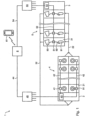
- FIG. 1 shows schematically a ring spinning system 1 according to the invention.
- the ring spinning system 1 contains a ring spinning machine 2 and a dishwasher 3.
- the ring spinning machine 2 has a large number of spinning positions 21. At each spinning point 21, yarn is spun from roving using the known ring spinning process and wound up into a so-called cop 91.
- the ring spinning machine 2 is equipped with a spinning monitoring system 4 for monitoring the operation of the spinning stations 21, e.g. B. equipped to detect thread breaks or “slow spindles”.
- the spinning monitoring system 4 contains a spinning sensor 41 at each of the spinning points 21.
- the spinning sensor 41 measures a spinning measurement variable.
- Each spinning sensor 41 is connected to a spinning monitoring control unit 43 via a wired or wireless first data line 42.
- the spinning sensor 41 sends values of the spinning measurement variable to the spinning monitoring control unit 43 via the first data line 42.
- the spinning monitoring control unit 43 receives the values. From this, it determines values of a parameter that is characteristic of the operation of the spinning station 21 for at least two different times during the winding of the cop 91 and stores the determined values together with associated first section information, which identifies the yarn sections wound up at the at least two different times, as spinning data.
- the parameters that are characteristic of the operation of the spinning station 21 are a number of thread breaks per unit of time, a ring rotor speed, an air temperature and an air humidity.
- the spinning data may relate to a particular cop 91 or to a group of cops 91 being produced at the same time, e.g. B. on cops 91 of several spinning stations 21 of the ring spinning machine 2 with the same article or on the cops 91 of all spinning stations 21 of the ring spinning machine 2. If the spinning data relate to a group of cops 91, an average value is determined for each of the at least two different times Values of all cops 91 in the group are calculated, and these average values are stored together with associated first section information as spinning data.
- the full cops 91 which are produced at the same time, are simultaneously deposited ("doffed") from the ring spinning machine 2 and then automatically transported to the winding machine 3, which in Figure 1 is indicated by dashed arrows 22.
- the winding machine 3 has a large number of winding units 31. At each winding station 31, yarn 92 is successively placed on a yarn spool 93 by several cops 91, e.g. B. a cross-wound bobbin, rewound.
- the dishwasher 3 is equipped with a yarn monitoring system 5 for monitoring properties of the yarn 92.
- the yarn monitoring system 5 includes a yarn sensor 51 at each of the winding stations.
- the yarn sensor 51 measures a yarn measurement variable.
- Each yarn sensor 51 is connected to a yarn monitoring control unit 53 via a wired or wireless second data line 52.
- the yarn sensor 51 sends values of the yarn measurement variable to the yarn monitoring control unit 53 via the second data line 52.
- the yarn monitoring control unit 53 receives the values.
- the yarn monitoring system 5 can z. B. can be designed as a yarn cleaner system, with each yarn sensor 51 being assigned a yarn cutting unit which removes unacceptable yarn defects from the yarn 92.
- the yarn data relates to the same cop 91 or to the same group of cops 91 as the spinning data. If the spinning data relates to a group of cops 91, an average of the values of all cops 91 in the group is calculated for each of the at least two different times, and these average values are stored together with associated second section information as yarn data.
- the ring spinning system 1 further includes a central control and evaluation device 6.
- the central control and evaluation device 6 is connected to the spinning monitoring control unit 43 via a wired or wireless third data line 44 and receives the spinning data from it.
- the central control and evaluation device 6 is also connected to the yarn monitoring control unit 53 via a wired or wireless fourth data line 54 and receives the yarn data from it.
- the central control and evaluation device 6 assigns the received spinning data and yarn data to one another based on the respective first and second section information in such a way that they relate to the same yarn section. It thereby provides a basis for an intervention on the ring spinning machine 2.
- the spinning data and yarn data to be assigned to one another must relate to the same cop 91 or to the same group of cops 91.
- Unwinding the cop 91 or the group of cops 91 is assigned to the cop 91 or the group of cops 91 and is stored as a key with both the spinning data and the yarn data.
- Such an identification of a point in time when the cop 91 or the group of cops 91 is unwrapped can, for. B. be a so-called doff number, ie a natural number that uniquely identifies a doffing ("doff") of simultaneously produced cops 91 from the ring spinning machine 2 and which is increased by one with each subsequent doff.
- the ring spinning system 1 is preferably equipped with a cop tracking system (not shown), which makes it possible to assign a cop 91 located in the dishwasher 3 to the spinning station 21 on which it was produced.
- a cop tracking system can be used for the above-mentioned identification of a point in time when the cop 91 or the group of cops 91 is unwrapped. It can provide the identification of the central control and evaluation device 6. In addition, it can assign an identification of the spinning station 21 on which a specific cop 91 was produced to the cop 91 and provide the assignment of the central control and evaluation device 6.
- the central control and evaluation device 6 can also store this identification as a key with both the spinning data and the yarn data in order to enable or facilitate the mutual assignment of the spinning data and the yarn data.
- the central control and evaluation device 6 can be designed as an independent device, e.g. B. as a computer that is located in the spinning mill or outside the spinning mill. Alternatively, the central control and evaluation device 6 can be integrated in another device, e.g. B. in a yarn testing device in the textile laboratory of the spinning mill, in the spinning monitoring control unit 43, in the yarn monitoring control unit 53 etc. In the latter two cases, there can be a direct data connection between the spinning monitoring control unit 43 and the yarn monitoring control unit 53, via which the two control units 43, 53 transmit data or exchange.
- the central control and evaluation device 6 is preferably connected to an input unit and/or an output unit which an operator can make inputs or receive outputs.
- a mobile device 61 e.g. B. a mobile phone, which communicates wirelessly with the central control and evaluation device 6, shown as an input and output unit.
- other known input units such as. B. a computer keyboard and output units such as. B. a computer screen can be used.
- the ring spinning system 1 includes several spinning monitoring systems 4 on one or more ring spinning machines 2, the spinning monitoring control units 43 of which are connected to a spinning expert system 45.
- the spinning expert system 45 is set up to receive, process and output data from the spinning monitoring control units 43 in a suitable form, as well as to control the spinning monitoring control units 43. It is in turn connected to the central control and evaluation device 6.
- the ring spinning system 1 includes several yarn monitoring systems 5 on one or more winding machines 3, the yarn monitoring control units 53 of which are connected to a yarn expert system 55.
- the gaming expert system 55 is set up to receive data from the yarn monitoring control units 53, process it and output it in a suitable form, as well as to control the yarn monitoring control units 53. It is in turn connected to the central control and evaluation device 6.
- the mutual assignment of the spinning data and the yarn data provides a basis for an intervention on the ring spinning machine 2.
- an intervention can take place automatically.
- the intervention can be carried out by an operator.
- the spinning data and yarn data assigned to one another are graphically displayed together, and the graphical representation of the spinning data and yarn data assigned to one another is used in a visually detectable form as the basis for the intervention to be carried out on the Ring spinning machine 2 issued to the operator. Examples of graphical representations are in the Figures 2-4 specified.
- Figure 2 shows a first example of a graphical representation 200 of the associated spinning data and yarn data, as it can be output to an operator in a visually detectable form.
- the output takes place on a known output unit connected to the central control and evaluation device 6, for example the mobile device 61 (see Figure 1 ).
- the representation 200 includes a schematic representation 210 of a cop 291 that was wound up from bottom to top.
- the vertical axes 221, 231, 241 thus essentially indicate a time course during which the cop 291 was wound up. But you can also specify a time course during the rewinding of the cop 291, a position along the longitudinal axis of the cop 291, a length of the yarn wound on the cop 291, a mass of the yarn wound on the cop 291, etc.
- An axis 211 with two different divisions drawn in the cop 291 indicates that there are several different, but essentially corresponding, options for defining the independent variables plotted along the vertical axes 221, 231, 241.
- a number of thread breaks per unit of time 222 is shown as a function of the time 221 during the winding of the cop 291 with bars 223.
- Each bar 223 corresponds to a certain unit of time during winding, for example 20 minutes, or a certain length of yarn, for example 250 m.
- This first diagram 220 represents spinning data.
- a time course of a ring rotor speed 232 during cop production is shown with a line 233.
- the ring runner is accelerated evenly. After reaching a predetermined speed, this is essentially used for the rest of the cop production maintained.
- the speed is slowed down to zero.
- the ring rotor speed can be determined in various ways, e.g. B. from a signal from the spinning sensor 41 (see Figure 1 ) or from the speed of a rotor of a motor driving the spindle.
- This second diagram 230 also represents spinning data.
- a number of yarn errors per unit of time 242 is shown as a function of time 241 during the rewinding of the cop with bars 243, the time axis 241 being scaled so that the total rewinding time is equal to the total cop production time.
- Each bar 243 corresponds to a specific one Unit of time, for example 40 seconds when rewinding or 40 minutes when winding, or a specific length of yarn, for example 1000 m.
- Each bar 243 is in the exemplary embodiment of Figure 2 divided into three areas 244-246 representing different types of yarn defects, e.g. B. Neps 244, thin places 245 and thick places 246.
- This third diagram 240 represents yarn data, which is thus assigned to the spinning data of the first diagram 220 and the second diagram 230, in such a way that they each relate to the same yarn section.
- the dependent variables shown in the three diagrams 220, 230, 240 can relate to a single cop or to a group of cops. In the latter case, the diagrams 220, 230, 240 each show mean values of the respective variables obtained from averaging over the entire group.
- the time-resolved, mutually assigned and possibly graphically displayed spinning data and yarn data allow the ring spinning process to be optimized. Based on the associated spinning data and yarn data, it can be assessed whether and, if so, what kind of intervention needs to be carried out on the ring spinning machine 2.
- Such an intervention can include, for example, a change in a specification for a spindle speed, a replacement of a ring rotor, a replacement of a stretching belt, a replacement of a printing cylinder, a change in the air temperature and/or a change in the humidity.
- a recommendation for intervention on the ring spinning machine 2 can be automatically generated and issued to the operator.
- the recommendation can be output in a visually detectable form, for example as text in the graphical representation 200, or in another form, for example acoustically.
- each of these diagrams 250, 260, 270 shows a bar 251, 261, 271.
- Each bar 251, 261, 271 is divided into three areas, which can, for example, have the traffic light colors green, yellow or red.
- An arrow 252, 262, 272 below the bar 251, 261, 271 indicates the period of use of the component and moves from left to right along a time axis 280 as the period of use increases. If the arrow 252, 262, 272 is in the first green area, the component is relatively new and should function properly.
- the component should be replaced occasionally.
- the arrow 252, 262, 272 in the third, red area indicates that the average service life of the component has been exceeded and the component must be replaced as soon as possible.
- the components whose service life is displayed can e.g. B. the ring runner, the printing cylinder or the stretching strap of the spinning station.
- these diagrams 250, 260, 270 can relate to a single cop or to a group of cops. Such diagrams can additionally support the decision about a possible intervention on the ring spinning machine 2.
- a frame 290 comprising all elements of the representation 200 indicates the visual comprehensibility of the graphic representation 200.
- the diagrams 220, 230, 240, which represent the associated spinning data and yarn data should be displayed simultaneously and close to each other, e.g. B. on the same screen page.
- Figure 3 shows a similar situation as Figure 2 , and corresponding elements are designated by analogous reference numerals.
- Diagrams 320, 330, 340 refer to two cops wound at different times. They each show a first, solid line 323.1, 333.1 or 343.1, which refers to a first cop, and a second, dashed line 323.2, 333.2 or 343.2, which refers to a second cop. Without loss of generality, we can assume that the second cop was wound up after the first cop.
- the first diagram 320 is divided into two areas 325, 326 by a straight line 324 parallel to the time axis 321, which determine the requirements for the productivity of the spinning station 21.
- a first area 325 the number of thread breaks per unit of time 322 is permissible, in a second area 326 it is impermissible.
- the first two parameter values of the first cop (line 323.1) and the first parameter value of the second cop (line 323.2) are invalid.
- the third diagram 340 is divided into three areas 346-348 by two straight lines 344, 345 parallel to the time axis 341, which determine the quality requirements for the yarn 92.
- a first area 346 the number of yarn defects per unit of time 342 is so small that the quality requirements are significantly exceeded, which presumably affects productivity. Therefore, a number of yarn defects per unit of time 342 in this first area 346 is undesirable. It is optimal if the number of yarn defects per unit of time 342 lies in a second range 347.
- the number of yarn defects per unit of time 342 is too high and therefore inadmissible.
- the first parameter value of the first cop (line 343.1) is invalid.
- FIG. 4 Another graphical representation of the associated spinning data and yarn data shows Figure 4 .
- the two-dimensional diagram 400 is spanned by the parameter 411, which is characteristic of the operation of the spinning station, on the one hand, and by the parameter 412, which is characteristic of the yarn, on the other hand.
- the values of these two parameters form coordinates of points 421.1, 421.2, which are shown in diagram 400. If the number and/or location of the corresponding ones in the Figures 2 and 3 If the parameter values shown do not match, the relevant values can be determined by interpolation and/or extrapolation of the existing values.
- the chart 400 of Figure 4 contains in contrast to the diagrams of the Figures 2 and 3 no axis corresponding to time. However, the time course can be indicated by arrows 422.1, 422.2 between two consecutive points.
- the diagram 400 is divided into six areas 431-436 by axially parallel straight lines 413-415. This division corresponds to that of Figure 3 , where the first diagram 320 is divided by the straight line 324 and the third diagram 340 by the straight lines 344, 345.
- B points that lie in the area 433, both a permissible parameter 411 characteristic of the spinning position and a permissible parameter 412 characteristic of the yarn;
- Points in area 434 have a permissible parameter 412 characteristic of the yarn, but an impermissible parameter 411 characteristic of the spinning position; etc.
- Examples of a possible intervention on the ring spinning machine 2 are given below, as they can be carried out according to the invention on the basis of the spinning data and yarn data assigned to one another.
- the intervention can be carried out automatically by the central control and evaluation device 6 or manually by an operator.
- the central control and evaluation device 6 is connected to a control unit of the ring spinning machine 2 and transmits corresponding control signals to it.
- a control unit of the ring spinning machine 2 is in Figure 1 not marked separately. In one embodiment, it may coincide with the spinning monitoring control unit 43.
- one or more recommendations for the intervention can at least be generated automatically and output to the operator in addition to the graphical display.
- a recommendation can include several options, e.g. E.g.: “Reduce the ring rotor speed or replace the stretching belt!”
- the first two parameter values of the first cop (line 323.1) are in the impermissible range 326.
- the first parameter value of the same cop in the third diagram 340 is also in the impermissible range 348.
- the reason for the impermissible parameter values may be that the increase is too rapid the speed of the ring rotor at the start of winding.
- the acceleration of the ring traveler at the start of winding is reduced as an intervention on the ring spinning machine 2.
- the final speed can be set slightly higher.
- the speed profile 333.2 which has been changed compared to the original speed profile 333.1, is in the second diagram 330 of Figure 3 shown.
- the effects of this intervention are checked based on the associated spinning data and yarn data. This is possible as soon as a second cop has been wound up at the same spinning station 21 as the first cop with the second speed profile 333.2 and rewound at any winding station 31.
- the spinning data of the second cop is shown in the first diagram 320 with the line 323.2, the yarn data in the third diagram 340 with the line 343.2.
- the yarn data are now all within the permissible range 347. Thanks to the intervention, it was achieved that the yarn quality on the second cop is essentially the same, while on the first cop it was much worse at the bottom of the cop than at the top.
- the first parameter value of the spinning data for the second cop is still in the impermissible range 326.
- further intervention can be carried out. This can e.g. B. consist in a further reduction in the acceleration of the ring rotor at the start of winding or in replacing the ring rotor. Care is taken to ensure that the yarn data remains within the permissible range 347.
- Each of the six areas 431-436 can be assigned a specific intervention on the ring spinning machine 2.
- the intervention can depend on at what time or at what location on the cop the relevant parameter values were determined. If e.g. B. points in the area 436, an intervention can be provided to reduce the speed of the ring rotor at the relevant time during winding. For points in area 434, replacement of the ring rotor can be provided as an intervention if this is due (pointer 352 in diagram 350 of Figure 3 in the second or third area of the bar 351), otherwise a reduction in the speed of the ring rotor at the relevant time. No intervention is necessary for points in the 433 area.
- the controlled variables are the parameter characteristic of the operation of the spinning station 21 and/or the parameter characteristic of the yarn.
- the desired state is that the parameter values are in the permissible ranges 325, 347 ( Figure 3 ) or 433 ( Figure 4 ) lay. If this is not the case, a specific intervention is carried out on the ring spinning machine 2 as a control intervention.
- the control takes place relatively slowly because it takes at least the time required for winding up a cop ("doff time") until the effect of the control intervention can be checked and, if necessary, a new control intervention can be made. Nevertheless, the regulation according to the invention solves the problem set at the beginning.
Landscapes
- Engineering & Computer Science (AREA)
- Mechanical Engineering (AREA)
- Textile Engineering (AREA)
- Quality & Reliability (AREA)
- Spinning Or Twisting Of Yarns (AREA)
- Filamentary Materials, Packages, And Safety Devices Therefor (AREA)
Description
- Die vorliegende Erfindung liegt auf dem Gebiet des Ringspinnens und insbesondere der Qualitätskontrolle beim Ringspinnen. Sie betrifft eine Ringspinnanlage und ein Verfahren zu ihrem Betrieb, gemäss den unabhängigen Patentansprüchen.
- Eine Ringspinnanlage beinhaltet üblicherweise eine Ringspinnmaschine und eine Spülmaschine.
- Die Ringspinnmaschine weist eine Vielzahl von Spinnstellen auf. An jeder Spinnstelle wird Vorgarn von einer Vorgarnspule abgezogen, verstreckt, verdreht (versponnen) und als Garn auf einen Kops (Garnspule) aufgewickelt. Systeme zur Überwachung des Betriebs der Spinnstellen, z. B. zum Erkennen von Fadenbrüchen oder "Schleicherspindeln" (d. h. Spindeln, die mit einer Eigendrehzahl unterhalb der eingestellten Maschinendrehzahl arbeiten), sind bekannt. Solche Spinnüberwachungssysteme messen typischerweise die Rotationsgeschwindigkeit des jeweiligen Ringläufers (z. B.
US-4,222,657 A ) oder des Garns (z. B.WO-2014/022189 A1 ). Zur ersteren Kategorie gehört das Ringspinnoptimiersystem USTER® SENTINEL, das in der Broschüre "USTER® SENTINEL - The ring spinning optimization system", Uster Technologies AG, 2016, beschrieben ist. Das Ringspinnoptimiersystem USTER® SENTINEL erstellt einen Kopsaufbaubericht, in dem unter anderem die durchschnittliche Anzahl Fadenbrüche und die durchschnittliche Rotationsgeschwindigkeit in Abhängigkeit von der Lage entlang einer Längsachse eines Kopses grafisch dargestellt sind. Der Kopsaufbaubericht wird auf einem Bildschirm an eine Bedienperson ausgegeben. - Die EP-3`293`295 A1 offenbart ein Messsystem für eine Spinnmaschine. An jeder Spinnstelle ist ein Sensor angebracht, aus dessen Signalen einerseits Produktionsparameter wie das Vorhandensein des Garns oder die Garngeschwindigkeit und andererseits Qualitätsparameter wie Masse, Dicke oder Reflektivität des Garns bestimmt werden. Diese Parameter werden an ein Informationssystem übermittelt, welches Information daraus zusammenstellt, verarbeitet und ausgibt.
- Die Kopse werden nach ihrer Herstellung von der Ringspinnmaschine zu einer Spulmaschine transportiert. Es sind Kopsverfolgungssysteme bekannt, die es ermöglichen, einem in der Spulmaschine befindlichen Kops diejenige Spinnstelle zuzuordnen, auf der er hergestellt wurde. Die Zuordnung kann bspw. mittels eines Identifikationsträgers auf der Kopshülse (z. B.
US-4,660,370 A ) oder auf einem Spulenteller (Caddy), der den Kops transportiert (z. B.DE-42'09'203 A1 ), erfolgen. - Die Spulmaschine weist eine Vielzahl von Spulstellen auf. An jeder Spulstelle werden mehrere Kopse nacheinander auf eine Kreuzspule umgespult. Das Umspulen hat den Zweck, grosse Garnspulen herzustellen, die effizient transportiert und verwendet werden können. Während des Umspulens werden Eigenschaften des Garns überwacht und mit vorgegebenen Qualitätskriterien verglichen. Bei Nichterfüllen der Qualitätskriterien kann die fehlerhafte Stelle aus dem Garn entfernt werden. Zu diesem Zweck sind so genannte Garnreinigersysteme bekannt, z. B. aus der
WO-2012/051730 A1 . - Die
WO-92/15737 A1 - Die EP-3'305'700 A1 offenbart ein Garnspulsystem mit einer automatischen Spulmaschine und einer vorgelagerten Maschine, z. B. einer Spinnmaschine. Die Spulmaschine beinhaltet eine Garnüberwachungseinheit und eine Übertragungseinheit zum Übertragen von Informationen über ein Überwachungsergebnis der Garnüberwachungseinheit an die Spinnmaschine. Die Spinnmaschine beinhaltet eine Empfangseinheit zum Empfangen der Informationen von der Spulmaschine. Dadurch kann sie rechtzeitig Anomalien erfassen.
- Die
DE-37' 12'654 A1 offenbart ein Verfahren zum Überwachen der Qualität von Produktionsstellen, Garnen und Spulen an einem Maschinenverbund aus wenigstens einer Ringspinnmaschine und wenigstens einem Spulautomaten. Die in der Ringspinnmaschine hergestellten Kopse werden einer zwischen Ringspinnmaschine und Spulautomat angeordneten Mess-, Zähl- und Sortiereinrichtung zugeführt, die jeden Kops der Spinnstelle zuordnet, von der er stammt. Eine zentrale Auswerteeinheit sammelt Daten von der Mess-, Zähl- und Sortiereinrichtung sowie Messdaten des Spinn- und des Spulprozesses. Sie kann die gesammelten Daten verknüpfen und zu Entscheidungshilfen und/oder zur Steuerung des Produktionsprozesses aufbereiten, statistisch auswerten und anzeigen. So kann rechtzeitig in den Produktionsprozess eingegriffen, der Kopstransport gelenkt oder eine Übersicht über den Qualitätszustand der Garne und der Maschine gewonnen werden. - In der
US-5,107,667 A wird ein Verwaltungsverfahren für Spinnmaschinen vorgeschlagen. Die Spinnereianlage ist mit einem Kopsverfolgungssystem ausgestattet. Beim Umspulen des Garns auf der Spulmaschine werden Garndefekte ermittelt. Mittels des Kopsverfolgungssystems werden fehlerhafte Spinnstellen der Ringspinnmaschine ermittelt. - Die
DE-43'06'095 A1 offenbart ein Verfahren und eine Einrichtung zum Steuern einer vernetzten Spinnereianlage. Die Spinnereianlage umfasst eine Ringspinnmaschine, einen der Ringspinnmaschine zugeordneten Bedienungsautomaten und eine mit der Ringspinnmaschine verkettete Spulmaschine mit einem Garnreiniger. Sie ist mit einem Kopsverfolgungssystem ausgestattet. Zur Optimierung der Spinnereianlage werden Informationen ausgetauscht. Der Bedienungsautomat führt nicht nur Bedienungsoperationen aus, sondern sammelt auch Informationen bezüglich der Zustände der Spinnstellen und der Fadenbrüche in den einzelnen Kopsen. Die Spulmaschine bzw. ihre Garnreiniger können über das Kopsverfolgungssystem feststellen, dass eine bestimmte Spindel der Ringspinnmaschine stets schlechtes Garn produziert. - Die
WO-2009/073993 A1 schlägt eine Vorrichtung und ein Verfahren zur Überwachung einer Mehrzahl von Arbeitsstellen einer Ringspinnmaschine vor. Die Vorrichtung hat mindestens einen Garnprüfer, der an einer Weiterverarbeitungsmaschine für das Garn angeordnet ist, und eine Überwachungseinheit, welche mit dem Garnprüfer verbunden ist. Um eine Identifikation der Arbeitsstellen der Ringspinnmaschine zu gewährleisten, ist ein an den Arbeitsstellen vorbei führbarer Tastkopf zur berührungslosen Aufnahme von Signalen vorgesehen, welcher an die Überwachungseinheit angeschlossen ist und einen ersten Sensor für die Überwachung der Arbeitsstellen und einen zweiten Sensor zur Datenerfassung auf Kopshülsen an den Arbeitsstellen aufweist. - Es ist eine Aufgabe der vorliegenden Erfindung, eine Ringspinnanlage und ein Verfahren zu ihrem Betrieb anzugeben, die eine höhere Produktivität und gleichzeitig ein angestrebtes Qualitätsniveau des gesponnenen Garns erreichen. Insbesondere soll die Qualität des Garns auf dem ganzen Kops im Wesentlichen dieselbe sein oder ihre Variation zumindest vermindert werden. Die Einsatzdauer von ersetzbaren Maschinenteilen soll erhöht werden.
- Diese und andere Aufgaben werden durch das Verfahren und die Ringspinnanlage gelöst, wie sie in den unabhängigen Patentansprüchen definiert sind. Vorteilhafte Ausführungsformen sind in den abhängigen Patentansprüchen angegeben.
- Die Erfindung beruht auf der Idee, für einen Kops einander entsprechende, zeitaufgelöste Werte eines für den Betrieb der Spinnstelle charakteristischen Parameters und Werte eines für das Garn charakteristischen Parameters einander derart automatisch zuzuordnen, dass sie sich auf denselben Garnabschnitt beziehen, und aufgrund der Zuordnung einen Eingriff an der Ringspinnmaschine vorzunehmen. Vorzugsweise werden die einander zugeordneten, zeitaufgelösten Werte grafisch dargestellt, und die grafische Darstellung wird in visuell erfassbarer Form an eine Bedienperson ausgegeben.
- Der Begriff "Garnabschnitt" bezeichnet in dieser Schrift eine zusammenhängende echte Teilmenge des auf einem Kops befindlichen Garns. Die Länge eines solchen Garnabschnitts kann zwischen ca. 1 mm und einem Grossteil der auf dem Kops befindlichen Gesamtlänge betragen.
- Das erfindungsgemässe Verfahren dient zum Betrieb einer Ringspinnanlage, welche eine Ringspinnmaschine mit einer Vielzahl von Spinnstellen und eine Spulmaschine mit einer Vielzahl von Spulstellen beinhaltet. An einer der Spinnstellen wird Garn gesponnen und zu einem Kops aufgewickelt. Der Kops wird automatisch von der Spinnstelle zu einer der Spulstellen transportiert. An der Spulstelle wird das Garn von dem Kops auf eine Garnspule umgespult. Werte eines für den Betrieb der Spinnstelle charakteristischen Parameters werden zu mindestens zwei verschiedenen Zeiten während des Aufwickelns des Kopses automatisch ermittelt und zusammen mit zugehörigen ersten Abschnittsinformationen, welche die zu den mindestens zwei verschiedenen Zeiten aufgewickelten Garnabschnitte identifizieren, als Spinndaten gespeichert. Werte eines für das Garn charakteristischen Parameters werden zu mindestens zwei verschiedenen Zeiten während des Umspulens des Kopses automatisch ermittelt und zusammen mit zugehörigen zweiten Abschnittsinformationen, welche die zu den mindestens zwei verschiedenen Zeiten umgespulten Garnabschnitte identifizieren, als Garndaten gespeichert. Die Spinndaten und die Garndaten werden aufgrund der jeweiligen ersten und zweiten Abschnittsinformationen einander derart automatisch zugeordnet, dass sie sich auf denselben Garnabschnitt beziehen. Aufgrund der einander zugeordneten Spinndaten und Garndaten wird ein Eingriff an der Ringspinnmaschine vorgenommen.
- In einer Ausführungsform wird an einer Mehrzahl von Spinnstellen gleichzeitig Garn gesponnen und zu Kopsen aufgewickelt, welche Kopse eine Gruppe von Kopsen bilden. Die Werte des für den Betrieb der Spinnstelle charakteristischen Parameters werden für die ganze Gruppe von Kopsen jeweils gleichzeitig automatisch ermittelt. Ein Mittelwert der Werte des für den Betrieb der Spinnstelle charakteristischen Parameters wird für die Gruppe von Kopsen für jede der verschiedenen Zeiten berechnet, und diese Mittelwerte werden zusammen mit zugehörigen ersten Abschnittsinformationen als Spinndaten gespeichert. Ein Mittelwert der Werte des für das Garn charakteristischen Parameters wird für dieselbe Gruppe von Kopsen für jede der verschiedenen Zeiten automatisch berechnet, und diese Mittelwerte werden zusammen mit zugehörigen zweiten Abschnittsinformationen als Garndaten gespeichert.
- In einer Ausführungsform beinhalten die ersten und/oder zweiten Abschnittsinformationen Informationen über einen Zeitpunkt, zu dem der betreffende Garnabschnitt aufgewickelt bzw. umgespult wird, und/oder Informationen über einen Ort auf dem Kops, auf dem der betreffende Garnabschnitt liegt.
- In einer Ausführungsform wird zur gegenseitigen automatischen Zuordnung der Spinndaten und der Garndaten eine Identifikation eines Zeitpunktes des Aufwickelns des Kopses bzw. der Gruppe von Kopsen dem Kops bzw. der Gruppe von Kopsen zugeordnet und als Schlüssel sowohl mit den Spinndaten als auch mit den Garndaten gespeichert wird. Zur gegenseitigen automatischen Zuordnung der Spinndaten und der Garndaten kann zusätzlich eine Identifikation der Spinnstelle dem Kops zugeordnet und als Schlüssel sowohl mit den Spinndaten als auch mit den Garndaten gespeichert werden.
- Der Eingriff an der Ringspinnmaschine umfasst z. B. eine Handlung aus der folgenden Menge: Änderung einer Vorgabe für eine Spindeldrehzahl, Austausch eines Ringläufers, Austausch eines Streckriemchens, Austausch eines Druckzylinders, Änderung der Lufttemperatur, Änderung der Luftfeuchtigkeit.
- Der von den Spinndaten umfasste für den Betrieb der Spinnstelle charakteristische Parameter wird z. B. aus der folgenden Menge ausgewählt: Anzahl Fadenbrüche pro Zeiteinheit, Ringläuferdrehzahl, Lufttemperatur, Luftfeuchtigkeit.
- Der von den Garndaten umfasste für das Garn charakteristische Parameter wird z. B. aus der folgenden Menge ausgewählt: Variationskoeffizient der Garnmasse, Variationskoeffizient des Garndurchmessers, Haarigkeit, Anzahl Dickstellen pro Längeneinheit, Anzahl Dünnstellen pro Längeneinheit, Anzahl periodische Garnfehler pro Längeneinheit, Anzahl Gamnummemschwankungen pro Längeneinheit, Anzahl Fremdstoffe pro Längeneinheit.
- Der Eingriff an der Ringspinnmaschine kann automatisch vorgenommen werden. In einer Ausführungsfonn werden die einander zugeordneten Spinndaten und Garndaten zusammen in einer grafischen Darstellung grafisch dargestellt, und die grafische Darstellung wird in visuell erfassbarer Form als Grundlage für den vorzunehmenden Eingriff an der Ringspinnmaschine an eine Bedienperson ausgegeben. Eine Empfehlung für den Eingriff an der Ringspinnmaschine kann automatisch erzeugt und zusätzlich zur grafischen Darstellung an die Bedienperson ausgegeben werden. Der Eingriff an der Ringspinnmaschine kann von der Bedienperson aufgrund der ausgegebenen grafischen Darstellung bzw. aufgrund der Empfehlung vorgenommen werden. Die grafische Darstellung der Spinndaten beinhaltet vorzugsweise ein Diagramm der mindestens zwei Werte des für den Betrieb der Spinnstelle charakteristischen Parameters in Abhängigkeit von der Lage entlang einer Längsachse eines Kopses oder in Abhängigkeit von der Zeit während des Aufwickelns ein und desselben Kopses, und die grafische Darstellung der Garndaten beinhaltet vorzugsweise ein Diagramm der mindestens zwei Werte des für das Garn charakteristischen Parameters in Abhängigkeit von derselben unabhängigen Variablen wie die Spinndaten. Die grafische Darstellung kann zusätzlich ein Diagramm beinhalten, das eine Grösse aus der folgenden Menge darstellt: Einsatzdauer eines Ringläufers, Einsatzdauer eines Druckzylinders, Einsatzdauer eines Streckriemchens.
- In einer Ausführungsform wird der Betrieb der Ringspinnanlage in einem geschlossenen Regelkreis geregelt, in welchem Regelkreis der für den Betrieb der Spinnstelle charakteristische Parameter und/oder der für das Garn charakteristische Parameter eine Regelgrösse ist und als Sollzustand angestrebt wird, dass die Werte des Parameters bzw. der Parameter in einem vorgegebenen Sollbereich liegen.
- Die erfindungsgemässe Ringspinnanlage beinhaltet eine Ringspinnmaschine mit einer Vielzahl von Spinnstellen zum Spinnen von Garn und zum Aufwickeln des Garns auf jeweils einen Kops und ein Spinnüberwachungssystem zur Überwachung des Betriebs der Spinnstellen, mit einem Spinnsensor an jeder der Spinnstellen zum Messen einer Spinnmessgrösse.. Ferner beinhaltet die Ringspinnanlage eine Spulmaschine mit einer Vielzahl von Spulstellen zum Umspulen des Garns von einem jeweiligen Kops auf eine Garnspule und ein Garnüberwachungssystem zur Überwachung von Eigenschaften des Garns, mit einem Garnsensor an jeder der Spulstellen zum Messen einer Garnmessgrösse. Ausserdem beinhaltet die Ringspinnanlage ein Transportsystem zum Transportieren des Kopses von der Spinnstelle zu einer der Spulstellen. Die Ringspinnanlage beinhaltet eine mit dem Spinnsensor verbundene Spinnüberwachungssteuereinheit, die dazu eingerichtet ist, Werte der Spinnmessgrösse vom Spinnsensor einer Spinnstelle zu empfangen, daraus zu mindestens zwei verschiedenen Zeiten während des Aufwickelns des Kopses Werte eines für den Betrieb der Spinnstelle charakteristischen Parameters zu ermitteln und die ermittelten Werte zusammen mit zugehörigen ersten Abschnittsinformationen, welche die zu den mindestens zwei verschiedenen Zeiten aufgewickelten Garnabschnitte identifizieren, als Spinndaten zu speichern. Die Ringspinnanlage beinhaltet eine mit dem Garnsensor verbundene Garnüberwachungssteuereinheit, die dazu eingerichtet ist, Werte der Garnmessgrösse vom Garnsensor einer Spulstelle zu empfangen, daraus zu mindestens zwei verschiedenen Zeiten während des Umspulens jeweils eines Kopses Werte eines für das Garn charakteristischen Parameters zu ermitteln und die ermittelten Werte zusammen mit zugehörigen zweiten Abschnittsinformationen, welche die zu den mindestens zwei verschiedenen Zeiten umgespulten Garnabschnitte identifizieren, als Garndaten zu speichern. Die Ringspinnanlage beinhaltet auch eine mit der Spinnüberwachungssteuereinheit und mit der Garnüberwachungssteuereinheit verbundene zentrale Steuer- und Auswerteeinrichtung, die dazu eingerichtet ist, die Spinndaten von der Spinnüberwachungssteuereinheit und die Garndaten von der Garnüberwachungssteuereinheit zu empfangen sowie die empfangenen Spinndaten und Garndaten aufgrund der jeweiligen ersten und zweiten Abschnittsinformationen einander derart zuzuordnen, dass sie sich auf denselben Garnabschnitt beziehen, um dadurch eine Grundlage für einen Eingriff an der Ringspinnmaschine zur Verfügung zu stellen.
- In einer Ausführungsform ist die zentrale Steuer- und Auswerteeinrichtung mit einer Steuereinheit der Ringspinnmaschine verbunden und dazu eingerichtet, den Eingriff an der Ringspinnmaschine automatisch vorzunehmen.
- In einer Ausführungsform ist die zentrale Steuer- und Auswerteeinrichtung mit einer Ausgabeeinheit verbunden und dazu eingerichtet, die einander zugeordneten Spinndaten und Garndaten zusammen in einer grafischen Darstellung grafisch darzustellen und auf der Ausgabeeinheit die grafische Darstellung in visuell erfassbarer Form auf der Ausgabeeinheit als Grundlage für den vorzunehmenden Eingriff an der Ringspinnmaschine an eine Bedienperson auszugeben.
- In einer Ausfuhrungsform ist die zentrale Steuer- und Auswerteeinrichtung dazu eingerichtet, eine Empfehlung für den Eingriff an der Ringspinnmaschine automatisch zu erzeugen und zusätzlich zur grafischen Darstellung an die Bedienperson auszugeben.
- In einer Ausführungsform beinhaltet die Ringspinnanlage mehrere Spinnüberwachungssysteme, deren Spinnüberwachungssteuereinheiten mit einem Spinnenexpertensystem verbunden sind, welches dazu eingerichtet ist, Daten von den Spinnüberwachungssteuereinheiten zu empfangen, zu verarbeiten und in geeigneter Form auszugeben, sowie die Spinnüberwachungssteuereinheiten zu steuern, und welches mit der zentralen Steuer- und Auswerteeinrichtung verbunden ist.
- In einer Ausführungsform beinhaltet die Ringspinnanlage mehrere Garnüberwachungssysteme, deren Garnüberwachungssteuereinheiten mit einem Garnexpertensystem verbunden sind, welches dazu eingerichtet ist, Daten von den Garnüberwachungssteuereinheiten zu empfangen, zu verarbeiten und in geeigneter Form auszugeben sowie die Garnüberwachungssteuereinheiten zu steuern, und welches mit der zentralen Steuer- und Auswerteeinrichtung verbunden ist.
- Ein Vorteil der Erfindung besteht in der Erhöhung der Produktivität bei Aufrechterhaltung des angestrebten Qualitätsniveaus des gesponnenen Garns. Einstellungen an der Ringspinnmaschine werden optimal vorgenommen, wodurch die Garnqualität erhöht und die Produktivität erhöht wird. Es wird eine gleich bleibende Garnqualität auf dem ganzen Kops erreicht. Dank der Erfindung werden systematische Qualitätsabweichungen im Garn schneller erkannt, und ihre Ursache wird behoben. Die zeitliche Auflösung der Spinndaten und der Garndaten sowie ihre gegenseitige Zuordnung ermöglichen einen differenzierten Eingriff an der Ringspinnmaschine. Die Erfindung ermöglicht es, die Einsatzdauer von Teilen der Ringspinnmaschine oder Verbrauchsmaterialien daran zu optimieren, indem diese nicht vorsorglich zu früh ersetzt zu werden brauchen, aber auch nicht zu spät ersetzt werden, was zu einer Produktivitätsminderung und/oder Qualitätsminderung führen würde. Die Erfindung bietet dem Bedienpersonal die Möglichkeit, neue Erkenntnisse über Zusammenhänge zwischen Spinndaten und Garndaten zu gewinnen und dank diesen den Spinnprozess weiter zu optimieren. Auswirkungen eines Eingriffs an der Ringspinnmaschine können über längere Zeit hinweg beobachtet und protokolliert werden. Mehrere gleichzeitig arbeitende Ringspinnmaschinen können miteinander verglichen werden, woraus insbesondere zwischen maschinenbezogenen Einflüssen und anderen Einflüssen wie Rohmaterial oder Umgebungsbedingungen unterschieden werden kann.
- Nachfolgend wird die Erfindung anhand der Zeichnungen detailliert erläutert.
- Figur 1
- zeigt schematisch eine erfindungsgemässe Ringspinnanlage.
- Figuren 2-4
- zeigen Beispiele von grafischen Darstellungen, wie sie im erfindungsgemässen Verfahren ausgegeben werden können.
-
Figur 1 zeigt schematisch eine erfindungsgemässe Ringspinnanlage 1. Die Ringspinnanlage 1 beinhaltet eine Ringspinnmaschine 2 und eine Spülmaschine 3. - Die Ringspinnmaschine 2 weist eine Vielzahl von Spinnstellen 21 auf. An jeder Spinnstelle 21 wird mittels des bekannten Ringspinnverfahrens Garn aus Vorgarn gesponnen und zu einem so genannten Kops 91 aufgewickelt. Die Ringspinnmaschine 2 ist mit einem Spinnüberwachungssystem 4 zur Überwachung des Betriebs der Spinnstellen 21, z. B. zum Erkennen von Fadenbrüchen oder "Schleicherspindeln", ausgerüstet. Das Spinnüberwachungssystem 4 beinhaltet an jeder der Spinnstellen 21 einen Spinnsensor 41. Der Spinnsensor 41 misst eine Spinnmessgrösse. Jeder Spinnsensor 41 ist über eine kabelgebundene oder kabellose erste Datenleitung 42 mit einer Spinnüberwachungssteuereinheit 43 verbunden. Der Spinnsensor 41 sendet über die erste Datenleitung 42 Werte der Spinnmessgrösse an die Spinnüberwachungssteuereinheit 43.
- Die Spinnüberwachungssteuereinheit 43 empfängt die Werte. Sie ermittelt daraus für mindestens zwei verschiedene Zeiten während des Aufwickelns des Kopses 91 Werte eines für den Betrieb der Spinnstelle 21 charakteristischen Parameters und speichert die ermittelten Werte zusammen mit zugehörigen ersten Abschnittsinformationen, welche die zu den mindestens zwei verschiedenen Zeiten aufgewickelten Garnabschnitte identifizieren, als Spinndaten. Beispiele für den für den Betrieb der Spinnstelle 21 charakteristischen Parameters sind eine Anzahl Fadenbrüche pro Zeiteinheit, eine Ringläuferdrehzahl, eine Lufttemperatur und eine Luftfeuchtigkeit.
- Die Spinndaten können sich auf einen bestimmten Kops 91 beziehen oder auf eine Gruppe von Kopsen 91, die gleichzeitig hergestellt werden, z. B. auf Kopse 91 mehrerer Spinnstellen 21 der Ringspinnmaschine 2 mit demselben Artikel oder auf die Kopse 91 aller Spinnstellen 21 der Ringspinnmaschine 2. Wenn sich die Spinndaten auf eine Gruppe von Kopsen 91 beziehen, so wird für jede der mindestens zwei verschiedenen Zeiten ein Mittelwert der Werte aller Kopse 91 der Gruppe berechnet, und diese Mittelwerte werden zusammen mit zugehörigen ersten Abschnittsinformationen als Spinndaten gespeichert.
- Die vollen, gleichzeitig hergestellten Kopse 91 werden gleichzeitig von der Ringspinnmaschine 2 abgesetzt ("gedofft") und anschliessend automatisch zur Spulmaschine 3 transportiert, was in
Figur 1 mit gestrichelten Pfeilen 22 angedeutet ist. - Die Spulmaschine 3 weist eine Vielzahl von Spulstellen 31 auf. An jeder Spulstelle 31 wird Garn 92 von mehreren Kopsen 91 nacheinander auf eine Garnspule 93, z. B. eine Kreuzspule, umgespult. Die Spülmaschine 3 ist mit einem Garnüberwachungssystem 5 zur Überwachung von Eigenschaften des Garns 92 ausgerüstet. Das Garnüberwachungssystem 5 beinhaltet an jeder der Spulstellen einen Garnsensor 51. Der Garnsensor 51 misst eine Garnmessgrösse. Jeder Garnsensor 51 ist über eine kabelgebundene oder kabellose zweite Datenleitung 52 mit einer Garnüberwachungssteuereinheit 53 verbunden. Der Garnsensor 51 sendet über die zweite Datenleitung 52 Werte der Garnmessgrösse an die Garnüberwachungssteuereinheit 53. Die Garnüberwachungssteuereinheit 53 empfängt die Werte. Sie ermittelt daraus für mindestens zwei verschiedene Zeiten während des Umspulens des Kopses 91 Werte eines für das Garn charakteristischen Parameters und speichert die ermittelten Werte zusammen mit zugehörigen zweiten Abschnittsinformationen, welche die zu den mindestens zwei verschiedenen Zeiten umgespulten Garnabschnitte identifizieren, als Garndaten. Beispiele für den für das Garn 92 charakteristischen Parameters sind ein Variationskoeffizient der Garnmasse, ein Variationskoeffizient des Garndurchmessers, eine Haarigkeit, eine Anzahl Dickstellen pro Längeneinheit, eine Anzahl Dünnstellen pro Längeneinheit, eine Anzahl periodische Garnfehler pro Längeneinheit, eine Anzahl Garnnummernschwankungen pro Längeneinheit und eine Anzahl Fremdstoffe pro Längeneinheit. Das Garnüberwachungssystem 5 kann z. B. als Garnreinigersystem ausgebildet sein, wobei jedem Garnsensor 51 eine Garnschneideinheit zugeordnet sein kann, die unzulässige Garnfehler aus dem Garn 92 entfernt.
- Die Garndaten beziehen sich auf denselben Kops 91 oder auf dieselbe Gruppe von Kopsen 91 wie die Spinndaten. Wenn sich die Spinndaten auf eine Gruppe von Kopsen 91 beziehen, so wird für jede der mindestens zwei verschiedenen Zeiten ein Mittelwert der Werte aller Kopse 91 der Gruppe berechnet, und diese Mittelwerte werden zusammen mit zugehörigen zweiten Abschnittsinformationen als Garndaten gespeichert.
- Leere Kopshülsen werden von der Spulmaschine 3 entfernt und wieder der Ringspinnmaschine 2 zugeführt, was in
Figur 1 mit gestrichelten Pfeilen 32 angedeutet ist. - Die erfindungsgemässe Ringspinnanlage 1 beinhaltet ferner eine zentrale Steuer- und Auswerteeinrichtung 6. Die zentrale Steuer- und Auswerteeinrichtung 6 ist über eine kabelgebundene oder kabellose dritte Datenleitung 44 mit der Spinnüberwachungssteuereinheit 43verbunden und empfängt von dieser die Spinndaten. Die zentrale Steuer- und Auswerteeinrichtung 6 ist ferner über eine kabelgebundene oder kabellose vierte Datenleitung 54 mit der Garnüberwachungssteuereinheit 53 verbunden und empfängt von dieser die Garndaten. Die zentrale Steuer- und Auswerteeinrichtung 6 ordnet diejenigen empfangenen Spinndaten und Garndaten aufgrund der jeweiligen ersten und zweiten Abschnittsinformationen einander derart zu, dass sie sich auf denselben Garnabschnitt beziehen. Dadurch stellt sie eine Grundlage für einen Eingriff an der Ringspinnmaschine 2 zur Verfügung. Die einander zuzuordnenden Spinndaten und Garndaten müssen sich auf denselben Kops 91 bzw. auf dieselbe Gruppe von Kopsen 91 beziehen. Dies kann sichergestellt werden, indem eine Identifikation eines Zeitpunktes des Auswickelns des Kopses 91 bzw. der Gruppe von Kopsen 91 dem Kops 91 bzw. der Gruppe von Kopsen 91 zugeordnet und als Schlüssel sowohl mit den Spinndaten als auch mit den Garndaten gespeichert wird. Eine solche Identifikation eines Zeitpunktes des Auswickelns des Kopses 91 bzw. der Gruppe von Kopsen 91 kann z. B. eine so genannte Doff-Nummer sein, d. h. eine natürliche Zahl, die ein Absetzen ("Doff") von gleichzeitig hergestellten Kopsen 91 von der Ringspinnmaschine 2 eindeutig identifiziert und die bei jedem nachfolgenden Doff um eins erhöht wird.
- Die Ringspinnanlage 1 ist vorzugsweise mit einem (nicht eingezeichneten) Kopsverfolgungssystem ausgestattet, das es ermöglicht, einem in der Spülmaschine 3 befindlichen Kops 91 diejenige Spinnstelle 21 zuzuordnen, auf der er hergestellt wurde. Solche Kopsverfolgungssysteme sind an sich bekannt und werden hier nicht weiter diskutiert. Falls vorhanden, kann das Kopsverfolgungssystem für die oben erwähnte Identifikation eines Zeitpunktes des Auswickelns des Kopses 91 bzw. der Gruppe von Kopsen 91 herangezogen werden. Es kann die Identifikation der zentralen Steuer- und Auswerteeinrichtung 6 zur Verfügung stellen. Zusätzlich kann es eine Identifikation der Spinnstelle 21, auf der ein bestimmter Kops 91 hergestellt wurde, dem Kops 91 zuordnen und die Zuordnung der zentralen Steuer- und Auswerteeinrichtung 6 zur Verfügung stellen. Die zentrale Steuer- und Auswerteeinrichtung 6 kann auch diese Identifikation als Schlüssel sowohl mit den Spinndaten als auch mit den Garndaten speichern, um die gegenseitige Zuordnung der Spinndaten und der Garndaten zu ermöglichen oder zu erleichtern.
- Die zentrale Steuer- und Auswerteeinrichtung 6 kann als ein eigenständiges Gerät ausgeführt sein, z. B. als ein Computer, der sich in der Spinnerei oder ausserhalb der Spinnerei befindet. Alternativ kann die zentrale Steuer- und Auswerteeinrichtung 6 in einem anderen Gerät integriert sein, z. B. in einem Garnprüfgerät im Textillabor der Spinnerei, in der Spinnüberwachungssteuereinheit 43, in der Garnüberwachungssteuereinheit 53 etc. In den letzteren beiden Fällen kann eine direkte Datenverbindung zwischen der Spinnüberwachungssteuereinheit 43 und der Garnüberwachungssteuereinheit 53 bestehen, über welche die beiden Steuereinheiten 43, 53 Daten übermitteln oder austauschen. Die zentrale Steuer- und Auswerteeinrichtung 6 ist vorzugsweise mit einer Eingabeeinheit und/oder einer Ausgabeeinheit verbunden, über welche eine Bedienperson Eingaben vornehmen bzw. Ausgaben empfangen kann. Im Ausführungsbeispiel von
Figur 1 ist ein mobiles Gerät 61, z. B. ein Mobiltelefon, das mit der zentralen Steuer- und Auswerteeinrichtung 6 drahtlos kommuniziert, als Ein- und Ausgabeeinheit eingezeichnet. Alternativ oder zusätzlich können andere an sich bekannte Eingabeeinheiten wie z. B. eine Computertastatur und Ausgabeeinheiten wie z. B. ein Computerbildschirm verwendet werden. - Entlang der dritten Datenleitung 44 und/oder der vierten Datenleitung 54 können sich weitere Einrichtungen befinden, welche die übermittelten Daten empfangen, bei Bedarf verarbeiten und weitersenden. In einer Ausführungsform beinhaltet die Ringspinnanlage 1 mehrere Spinnüberwachungssysteme 4 auf einer oder mehreren Ringspinnmaschinen 2, deren Spinnüberwachungssteuereinheiten 43 mit einem Spinnenexpertensystem 45 verbunden sind. Das Spinnexpertensystem 45 ist dazu eingerichtet, Daten von den Spinnüberwachungssteuereinheiten 43 zu empfangen, zu verarbeiten und in geeigneter Form auszugeben, sowie die Spinnüberwachungssteuereinheiten 43 zu steuern. Es ist seinerseits mit der zentralen Steuer- und Auswerteeinrichtung 6 verbunden.
- In einer Ausfuhrungsform beinhaltet die Ringspinnanlage 1 mehrere Garnüberwachungssysteme 5 auf einer oder mehreren Spulmaschinen 3, deren Garnüberwachungssteuereinheiten 53 mit einem Garnexpertensystem 55 verbunden sind. Das Gamexpertensystem 55 ist dazu eingerichtet, Daten von den Garnüberwachungssteuereinheiten 53 zu empfangen, zu verarbeiten und in geeigneter Form auszugeben, sowie die Garnüberwachungssteuereinheiten 53 zu steuern. Es ist seinerseits mit der zentralen Steuer- und Auswerteeinrichtung 6 verbunden.
- Durch die gegenseitige Zuordnung der Spinndaten und der Garndaten wird eine Grundlage für einen Eingriff an der Ringspinnmaschine 2 zur Verfügung gestellt. Ein solcher Eingriff kann einerseits automatisch erfolgen. Andererseits kann der Eingriff von einer Bedienperson durchgeführt werden. Zum letzteren Zweck werden die einander zugeordneten Spinndaten und Garndaten zusammen grafisch dargestellt, und die grafische Darstellung der einander zugeordneten Spinndaten und Garndaten wird in visuell erfassbarer Form als Grundlage für den vorzunehmenden Eingriff an der Ringspinnmaschine 2 an die Bedienperson ausgegeben. Beispiele für grafische Darstellungen sind in den
Figuren 2-4 angegeben. -
Figur 2 zeigt ein erstes Beispiel einer grafischen Darstellung 200 der einander zugeordneten Spinndaten und Garndaten, wie sie in visuell erfassbarer Form an eine Bedienperson ausgegeben werden kann. Die Ausgabe erfolgt auf einem an sich bekannten, mit der zentralen Steuer- und Auswerteeinrichtung 6 verbundenen Ausgabeeinheit, bspw. dem mobilen Gerät 61 (sieheFigur 1 ). - Die Darstellung 200 beinhaltet eine schematische Darstellung 210 eines Kopses 291, der von unten nach oben aufgewickelt wurde. Rechts der Darstellung 210 des Kopses 291 befinden sich drei Diagramme 220, 230, 240, deren vertikale Achsen 221, 231, 241 jeweils der Längsachse (Rotationsachse) des Kopses 291 entsprechen. Die vertikalen Achsen 221, 231, 241 geben somit im Wesentlichen einen Zeitverlauf an, während dessen der Kops 291 aufgewickelt wurde. Sie können aber ebenso gut einen Zeitverlauf während des Umspulens des Kopses 291, eine Position entlang der Längsachse des Kopses 291, eine Länge des auf dem Kops 291 aufgewickelten Garns, eine Masse des auf dem Kops 291 aufgewickelten Garns etc. angeben. Eine im Kops 291 eingezeichnete Achse 211 mit zwei verschiedenen Teilungen deutet an, dass es hier mehrere verschiedene, im Wesentlichen jedoch einander entsprechende Möglichkeiten zur Definition der entlang der vertikalen Achsen 221, 231, 241 aufgetragenen unabhängigen Variablen gibt.
- In einem ersten Diagramm 220 der Darstellung 200 ist eine Anzahl Fadenbrüche pro Zeiteinheit 222 als Funktion der Zeit 221 während des Aufwickelns des Kopses 291 mit Balken 223 dargestellt. Jeder Balken 223 entspricht einer bestimmten Zeiteinheit beim Aufwickeln, bspw. 20 Minuten, oder einer bestimmten Garnlänge, bspw. 250 m. Zu Beginn der Kopsherstellung gab es in diesem Beispiel relativ viele Fadenbrüche, später weniger. Dieses erste Diagramm 220 stellt Spinndaten dar.
- In einem zweiten Diagramm 230 ist ein zeitlicher Verlauf einer Ringläuferdrehzahl 232 während der Kopsherstellung mit einer Linie 233 dargestellt. Zu Beginn der Kopsherstellung wird der Ringläufer gleichmässig beschleunigt. Nach Erreichen einer vorgegebenen Drehzahl wird diese im Wesentlichen für den Rest der Kopsherstellung beibehalten. Am Ende der Kopsherstellung wird die Drehzahl auf null abgebremst. Die Ringläuferdrehzahl kann auf verschiedene Arten ermittelt werden, z. B. aus einem Signal des Spinnsensors 41 (siehe
Figur 1 ) oder aus der Drehzahl eines Rotors eines die Spindel antreibenden Motors. Dieses zweite Diagramm 230 stellt ebenfalls Spinndaten dar. - In einem dritten Diagramm 240 ist eine Anzahl Garnfehler pro Zeiteinheit 242 als Funktion der Zeit 241 während des Umspulens des Kopses mit Balken 243 dargestellt, wobei die Zeitachse 241 so skaliert ist, dass die totale Umspulzeit gleich der totalen Kopsherstellungszeit ist Jeder Balken 243 entspricht einer bestimmten Zeiteinheit, bspw. 40 Sekunden beim Umspulen bzw. 40 Minuten beim Aufwickeln, oder einer bestimmten Garnlänge, bspw. 1000 m. Jeder Balken 243 ist im Ausfuhrungsbeispiel von
Figur 2 in drei Bereiche 244-246 aufgeteilt, die verschiedene Arten von Garnfehlern darstellen, z. B. Nissen 244, Dünnstellen 245 und Dickstellen 246. Die Anzahl Balken 243 in diesem dritten Diagramm 240 braucht nicht dieselbe zu sein wie im ersten Diagramm 220. Das am unteren Ende des Kopses 291 befindliche Garn weist mehr Garnfehler auf als das restliche Garn. Dieses dritte Diagramm 240 stellt Garndaten dar, die somit den Spinndaten des ersten Diagramms 220 und des zweiten Diagramms 230 zugeordnet sind, und zwar derart, dass die sich jeweils auf denselben Garnabschnitt beziehen. - Die in den drei Diagrammen 220, 230, 240 dargestellten abhängigen Variablen können sich auf einen einzelnen Kops oder auf eine Gruppe von Kopsen beziehen. Im letzteren Fall zeigen die Diagramme 220, 230, 240 jeweils aus einer Mittelwertbildung über die ganze Gruppe erhaltene Mittelwerte der jeweiligen Variablen. Die Darstellung 210 des Kopses 291, die ohnehin nur schematisch ist, repräsentiert dann die Gruppe von Kopsen.
- Die zeitaufgelösten, einander zugeordneten und allenfalls zusammen grafisch dargestellten Spinndaten und Garndaten erlauben es, den Ringspinnprozess zu optimieren. Aufgrund der einander zugeordneten Spinndaten und Garndaten kann beurteilt werden, ob und allenfalls was für ein Eingriff an der Ringspinnmaschine 2 vorzunehmen ist. Ein solcher Eingriff kann bspw. eine Änderung einer Vorgabe für eine Spindeldrehzahl, einen Austausch eines Ringläufers, einen Austausch eines Streckriemchens, einen Austausch eines Druckzylinders, eine Änderung der Lufttemperatur und/oder eine Änderung der Luftfeuchtigkeit beinhalten.
- Zusätzlich zur Ausgabe der grafischen Darstellung 200 gemäss
Figur 2 kann eine Empfehlung für den Eingriff an der Ringspinnmaschine 2 automatisch erzeugt und an die Bedienperson ausgegeben werden. Die Ausgabe der Empfehlung kann in visuell erfassbarer Form erfolgen, bspw. als Text in der grafischen Darstellung 200, oder in anderer Form, bspw. akustisch. - Links des Kopses 291 sind in der grafischen Darstellung 200 von
Figur 2 drei Diagramme 250, 260, 270 dargestellt, die jeweils eine Einsatzdauer eines Bauteils der Spinnstelle 21 veranschaulichen. Jedes dieser Diagramme 250, 260, 270 zeigt einen Balken 251, 261, 271. Jeder Balken 251, 261, 271 ist in drei Bereiche unterteilt, die bspw. die Ampelfarben Grün, Gelb bzw. Rot haben können. Ein Pfeil 252, 262, 272 unterhalb des Balkens 251, 261, 271 zeigt die Einsatzdauer des Bauteils an und verschiebt sich mit zunehmender Einsatzdauer entlang einer Zeitachse 280 von links nach rechts. Ist der Pfeil 252, 262, 272 im ersten, grünen Bereich, so ist das Bauteil relativ neu und sollte ordnungsgemäss funktionieren. Ist der Pfeil 252, 262, 272 im zweiten, gelben Bereich, so sollte das Bauteil gelegentlich ersetzt werden. Der Pfeil 252, 262, 272 im dritten, roten Bereich zeigt an, dass die mittlere Lebensdauer des Bauteils überschritten wurde und das Bauteil möglichst bald ersetzt werden muss. Die Bauteile, deren Einsatzdauer angezeigt wird, können z. B. der Ringläufer, der Druckzylinder bzw. das Streckriemchen der Spinnstelle sein. Entsprechend den Diagrammen 220, 230, 240 rechts des Kopses 291 können sich diese Diagramme 250, 260, 270 auf einen einzelnen Kops oder auf eine Gruppe von Kopsen beziehen. Solche Diagramme können die Entscheidung über einen möglichen Eingriff an der Ringspinnmaschine 2 zusätzlich unterstützen. - Ein alle Elemente der Darstellung 200 umfassender Rahmen 290 deutet die visuelle Erfassbarkeit der grafischen Darstellung 200 an. Insbesondere die Diagramme 220, 230, 240, welche die einander zugeordneten Spinndaten und Garndaten darstellen, sollten gleichzeitig und nahe beieinander, z. B. auf derselben Bildschirmseite, ausgegeben werden.
-
Figur 3 zeigt einen ähnlichen Sachverhalt wieFigur 2 , und einander entsprechende Elemente sind mit analogen Bezugszeichen bezeichnet. - Im Unterschied zur grafischen Darstellung 200 von
Figur 2 wurden in der grafischen Darstellung 300 vonFigur 3 die beiden Balkendiagramme 220, 240 durch Liniendiagramme 320, 340 ersetzt. Dies soll veranschaulichen, dass die vorliegende Erfindung nicht auf bestimmte Arten von Diagrammen beschränkt ist. Weitere Diagrammtypen für die grafische Darstellung der einander zugeordneten Spinndaten und Garndaten sind möglich und an sich bekannt. Verschiedene Diagrammtypen können miteinander in einer grafischen Darstellung kombiniert werden. - Die Diagramme 320, 330, 340 beziehen sich auf zwei Kopse, die zu verschiedenen Zeiten aufgewickelt wurden. Sie zeigen jeweils eine erste, durchgezogene Linie 323.1, 333.1 bzw. 343.1, die sich auf einen ersten Kops bezieht, und eine zweite, gestrichelte Linie 323.2, 333.2 bzw. 343.2, die sich auf einen zweiten Kops bezieht. Ohne Einschränkung der Allgemeinheit können wir annehmen, der zweite Kops sei nach dem ersten Kops aufgewickelt worden.
- Das erste Diagramm 320 ist durch eine zur Zeitachse 321 parallele Gerade 324 in zwei Bereiche 325, 326 unterteilt, welche die Anforderungen für die Produktivität der Spinnstelle 21 festlegen. In einem ersten Bereich 325 ist die Anzahl Fadenbrüche pro Zeiteinheit 322 zulässig, in einem zweiten Bereich 326 unzulässig. Im Beispiel von
Figur 3 sind die ersten beiden Parameterwerte des ersten Kopses (Linie 323.1) und der erste Parameterwert des zweiten Kopses (Linie 323.2) unzulässig. - Das dritte Diagramm 340 ist durch zwei zur Zeitachse 341 parallele Geraden 344, 345 in drei Bereiche 346-348 unterteilt, welche die Qualitätsanforderungen für das Garn 92 festlegen. In einem ersten Bereich 346 ist die Anzahl Garnfehler pro Zeiteinheit 342 so klein, dass die Qualitätsanforderungen deutlich übertroffen werden, worunter vermutlich die Produktivität leidet. Deshalb ist eine in diesem ersten Bereich 346 liegende Anzahl Garnfehler pro Zeiteinheit 342 unerwünscht. Optimal ist es, wenn die Anzahl Garnfehler pro Zeiteinheit 342 in einem zweiten Bereich 347 liegt. In einem dritten Bereich 348 hingegen ist die Anzahl Garnfehler pro Zeiteinheit 342 zu hoch und deshalb unzulässig. Im Beispiel von
Figur 3 ist der erste Parameterwert des ersten Kopses (Linie 343.1) unzulässig. - Eine andere grafische Darstellung der einander zugeordneten Spinndaten und Garndaten zeigt
Figur 4 . Hier sind die Spinndaten und die ihnen zugeordneten Garndaten nicht in mehreren separaten Diagrammen, sondern zusammen in einem einzigen Diagramm 400 dargestellt. Das zweidimensionale Diagramm 400 wird durch den für den für den Betrieb der Spinnstelle charakteristischen Parameter 411 einerseits und durch den für das Garn charakteristischen Parameter 412 andererseits aufgespannt. Die Werte dieser beiden Parameter bilden Koordinaten von Punkten 421.1, 421.2, die im Diagramm 400 eingezeichnet sind. Falls die Anzahl und/oder die Lage der entsprechenden, in denFiguren 2 und3 eingezeichneten Parameterwerte nicht übereinstimmt, können die betreffenden Werte durch Interpolation und/oder Extrapolation der vorhandenen Werte ermittelt werden. Das Diagramm 400 vonFigur 4 enthält im Gegensatz zu den Diagrammen derFiguren 2 und3 keine der Zeit entsprechende Achse. Der zeitliche Verlauf kann aber durch Pfeile 422.1, 422.2 zwischen jeweils zwei zeitlich aufeinander folgenden Punkten angedeutet werden. - Das Diagramm 400 ist durch achsparallele Geraden 413-415 in sechs Bereiche 431-436 unterteilt. Diese Unterteilung entspricht derjenigen von
Figur 3 , wo das erste Diagramm 320 durch die Gerade 324 und das dritte Diagramm 340 durch die Geraden 344, 345 unterteilt ist. Somit haben z. B. Punkte, die im Bereich 433 liegen, sowohl einen zulässigen für die Spinnstelle charakteristischen Parameter 411 als auch einen zulässigen für das Garn charakteristischen Parameter 412; Punkte im Bereich 434 haben zwar einen zulässigen für das Garn charakteristischen Parameter 412, aber einen unzulässigen für die Spinnstelle charakteristischen Parameter 411; usw. - Nachfolgend werden Beispiele für einen möglichen Eingriff an der Ringspinnmaschine 2 angegeben, wie sie erfindungsgemäss aufgrund der einander zugeordneten Spinndaten und Garndaten vorgenommen werden können. Der Eingriff kann automatisch durch die zentrale Steuer- und Auswerteeinrichtung 6 oder manuell durch eine Bedienperson erfolgen.
- Für einen automatischen Eingriff ist die zentrale Steuer- und Auswerteeinrichtung 6 mit einer Steuereinheit der Ringspinnmaschine 2 verbunden und übermittelt ihr entsprechende Steuersignale. Eine solche Steuereinheit der Ringspinnmaschine 2 ist in
Figur 1 nicht separat eingezeichnet. In einer Ausführungsform kann sie mit der Spinnüberwachungssteuereinheit 43 zusammenfallen. - Für einen manuellen Eingriff können eine oder mehrere Empfehlungen für den Eingriff zumindest automatisch erzeugt und zusätzlich zur grafischen Darstellung an die Bedienperson ausgegeben werden. Eine solche Empfehlung kann mehrere Optionen beinhalten, z. B.: "Ringläuferdrehzahl verringern oder Streckriemchen ersetzen!"
- Betrachten wir zuerst das Beispiel von
Figur 3 . Im ersten Diagramm 320 liegen die ersten beiden Parameterwerte des ersten Kopses (Linie 323.1) im unzulässigen Bereich 326. Auch der erste Parameterwert desselben Kopses im dritten Diagramm 340 liegt im unzulässigen Bereich 348. Die Ursache für die unzulässigen Parameterwerte liegt möglicherweise in einem zu schnellen Anstieg der Drehzahl des Ringläufers zu Beginn des Aufwickelns. Um die Anzahl Fadenbrüche pro Zeiteinheit 322 und die Anzahl Garnfehler pro Zeiteinheit 342 zu Beginn des Aufwickelns zu reduzieren, wird als Eingriff an der Ringspinnmaschine 2 die Beschleunigung des Ringläufers zu Beginn des Aufwickelns verringert. Als Kompensation für die dadurch verlorene Zeit kann dafür die Enddrehzahl etwas höher gesetzt werden. Das gegenüber dem ursprünglichen Drehzahlprofil 333.1 so geänderte Drehzahlprofil 333.2 ist im zweiten Diagramm 330 vonFigur 3 dargestellt. - Die Auswirkungen dieses Eingriffs werden aufgrund der einander zugeordneten Spinndaten und Garndaten überprüft. Dies ist möglich, sobald ein zweiter Kops an derselben Spinnstelle 21 wie der erste Kops mit dem zweiten Drehzahlprofil 333.2 aufgewickelt und an irgendeiner Spulstelle 31 umgespult wurde. Die Spinndaten des zweiten Kopses sind im ersten Diagramm 320 mit der Linie 323.2, die Garndaten im dritten Diagramm 340 mit der Linie 343.2 dargestellt. Die Garndaten liegen nun alle im zulässigen Bereich 347. Dank dem Eingriff wurde also erreicht, dass die Garnqualität auf dem zweiten Kops im Wesentlichen dieselbe ist, während sie auf dem ersten Kops am unteren Ende des Kopses viel schlechter war als am oberen Ende. Kann die gleichbleibende Garnqualität für die später aufgewickelten Kopse aufrechterhalten werden, so resultieren auch Garnspulen ohne nennenswerte Qualitätsschwankungen innerhalb der Spule, was ein grosser Vorteil ist Der erste Parameterwert der Spinndaten liegt für den zweiten Kops immer noch im unzulässigen Bereich 326. Um die Spinndaten weiter zu verbessern, kann ein erneuter Eingriff vorgenommen werden. Dieser kann z. B. in einer weiteren Verringerung der Beschleunigung des Ringläufers zu Beginn des Aufwickelns oder in einem Ersetzen des Ringläufers bestehen. Dabei wird darauf geachtet, dass die Garndaten weiterhin im zulässigen Bereich 347 bleiben.
- Im Diagramm 400 von
Figur 4 kann jedem der sechs Bereiche 431-436 ein bestimmter Eingriff an der Ringspinnmaschine 2 zugewiesen werden. Zusätzlich kann der Eingriff davon abhängen, zu welcher Zeit bzw. an welcher Stelle des Kopses die betreffenden Parameterwerte ermittelt wurden. Falls z. B. Punkte im Bereich 436 liegen, kann als Eingriff vorgesehen sein, zum betreffenden Zeitpunkt während des Aufwickelns die Drehzahl des Ringläufers zu reduzieren. Für Punkte im Bereich 434 kann als Eingriff ein Ersetzen des Ringläufers vorgesehen sein, falls dies fällig ist (Zeiger 352 im Diagramm 350 vonFigur 3 im zweiten oder dritten Bereich des Balkens 351), ansonsten eine Reduktion der Drehzahl des Ringläufers zum betreffenden Zeitpunkt. Bei Punkten im Bereich 433 ist kein Eingriff nötig. - Wird das erfindungsgemässe Verfahren mehrmals nacheinander ausgeführt, so liegt ein geschlossener Regelkreis für den Betrieb der Ringspinnanlage 1 vor. Die Regelgrössen sind der für den Betrieb der Spinnstelle 21 charakteristische Parameter und/oder der für das Garn charakteristische Parameter. Als Sollzustand wird angestrebt, dass die Parameterwerte in den zulässigen Bereichen 325, 347 (
Figur 3 ) bzw. 433 (Figur 4 ) liegen. Ist dies nicht der Fall, so wird als Regeleingriff ein bestimmter Eingriff an der Ringspinnmaschine 2 vorgenommen. Die Regelung erfolgt relativ langsam, weil es mindestens eine für das Aufwickeln eines Kopses benötigte Zeit ("Doff-Zeit") dauert, bis die Auswirkung des Regeleingriffs überprüft und bei Bedarf ein erneuter Regeleingriff vorgenommen werden kann. Dennoch löst die erfindungsgemässe Regelung die eingangs gestellte Aufgabe. -
- 1
- Ringspinnanlage
- 2
- Ringspinnmaschine
- 21
- Spinnstelle
- 22
- Transport eines Kopses von der Ringspinnmaschine zur Spulmaschine
- 3
- Spülmaschine
- 31
- Spulstelle
- 32
- Zuführung leerer Kopshülsen von der Spulmaschine zur Ringspinnmaschine
- 4
- Spinnüberwachungssystem
- 41
- Spinnsensor
- 42
- erste Datenleitung
- 43
- Spinnüberwachungssteuereinheit
- 44
- dritte Datenleitung
- 45
- Spinnexpertensystem
- 5
- Garnüberwachungssystem
- 51
- Garnsensor
- 52
- zweite Datenleitung
- 53
- Garnüberwachungssteuereinheit
- 54
- vierte Datenleitung
- 55
- Gamexpertensystem
- 6
- zentrale Steuer- und Auswerteeinrichtung
- 61
- mobiles Gerät
- 91
- Kops
- 92
- Garn
- 93
- Garnspule
- 200, 300
- grafische Darstellung
- 210, 310
- Darstellung eines Kopses
- 211, 311
- Kopsachse
- 220, 320
- erstes Diagramm
- 221,321
- Zeitachse
- 222, 322
- Achse der Anzahl Fadenbrüche pro Zeiteinheit
- 223
- Balken für Anzahl Fadenbrüche pro Zeiteinheit
- 230, 330
- zweites Diagramm
- 231,331
- Zeitachse
- 232, 332
- Achse der Ringläuferdrehzahl
- 233; 333.1, 333.2
- zeitlicher Verlauf der Ringläuferdrehzahl
- 240, 340
- drittes Diagramm
- 241,341
- Zeitachse
- 242, 342
- Achse der Anzahl Garnfehler pro Zeiteinheit
- 243
- Balken für Garnfehler pro Zeiteinheit
- 244
- Balken für Nissen
- 245
- Balken für Dünnstellen
- 246
- Balken für Dickstellen
- 250, 260, 270; 350, 360, 370
- Diagramme für Einsatzdauer von Bauteilen von Spinnstellen
- 251, 261, 271; 351, 361, 371
- Balken zur Darstellung der Einsatzdauer von Bauteilen von Spinnstellen
- 252, 262, 272; 352, 362, 372
- Pfeile zur Anzeige der Einsatzdauer von Bauteilen von Spinnstellen
- 280, 380
- Zeitachse
- 290,390
- Diagrammrahmen
- 291, 391
- dargestellter Kops
- 323.1, 323.2
- Verlauf der Anzahl Fadenbrüche pro Zeiteinheit
- 324
- zur Zeitachse parallele Gerade
- 325
- zulässiger Bereich für Anzahl Fadenbrüche pro Zeiteinheit
- 326
- unzulässiger Bereich für Anzahl Fadenbrüche pro Zeiteinheit
- 343.1, 343.2
- Verlauf der Anzahl Garnfehler pro Zeiteinheit
- 344, 345
- zur Zeitachse parallele Linien
- 346
- unerwünschter Bereich für Anzahl Garnfehler pro Zeiteinheit
- 347
- erwünschter Bereich für Anzahl Garnfehler pro Zeiteinheit
- 348
- unzulässiger Bereich für Anzahl Garnfehler pro Zeiteinheit
- 400
- Diagramm
- 411
- Achse für Spinnparameter
- 412
- Achse für Garnparameter
- 413-415
- achsparallele Geraden
- 421.1,421.2
- Punkte
- 422.1, 422.2
- Pfeile
- 431-436
- Bereiche mit unterschiedlichen Erwünschtheits- und Zulässigkeitsgraden
Claims (19)
- Verfahren zum Betrieb einer Ringspinnanlage (1), welche eine Ringspinnmaschine (2) mit einer Vielzahl von Spinnstellen (21) und eine Spulmaschine (3) mit einer Vielzahl von Spulstellen (31) beinhaltet, wobeian einer der Spinnstellen (21) Garn (92) gesponnen und zu einem Kops (91) aufgewickelt wird,der Kops (91) automatisch von der Spinnstelle (21) zu einer der Spulstellen (31) transportiert wird,an der Spulstelle (31) das Garn (92) von dem Kops (91) auf eine Garnspule (93) umgespult wird undWerte eines für den Betrieb der Spinnstelle (21) charakteristischen Parameters zu mindestens zwei verschiedenen Zeiten während des Aufwickelns des Kopses (91) automatisch ermittelt und zusammen mit zugehörigen ersten Abschnittsinformationen, welche die zu den mindestens zwei verschiedenen Zeiten aufgewickelten Garnabschnitte identifizieren, als Spinndaten gespeichert werden,dadurch gekennzeichnet, dassWerte eines für das Garn (92) charakteristischen Parameters zu mindestens zwei verschiedenen Zeiten während des Umspulens des Kopses (91) automatisch ermittelt und zusammen mit zugehörigen zweiten Abschnittsinformationen, welche die zu den mindestens zwei verschiedenen Zeiten umgespulten Garnabschnitte identifizieren, als Garndaten gespeichert werden,die Spinndaten und die Garndaten aufgrund der jeweiligen ersten und zweiten Abschnittsinformationen einander derart automatisch zugeordnet werden, dass sie sich auf denselben Garnabschnitt beziehen, undaufgrund der einander zugeordneten Spinndaten und Garndaten ein Eingriff an der Ringspinnmaschine (2) vorgenommen wird.
- Verfahren nach Anspruch 1, wobeian einer Mehrzahl von Spinnstellen (21) gleichzeitig Garn (92) gesponnen und zu Kopsen (91) aufgewickelt wird, welche Kopse (91) eine Gruppe von Kopsen (91) bilden,die Werte des für den Betrieb der Spinnstelle (21) charakteristischen Parameters für die ganze Gruppe von Kopsen (91) jeweils gleichzeitig automatisch ermittelt werden, ein Mittelwert der Werte des für den Betrieb der Spinnstelle (21) charakteristischen Parameters für die Gruppe von Kopsen (91) für jede der verschiedenen Zeiten automatisch berechnet wird und diese Mittelwerte zusammen mit zugehörigen ersten Abschnittsinformationen als Spinndaten gespeichert werden, undein Mittelwert der Werte des für das Garn (92) charakteristischen Parameters für dieselbe Gruppe von Kopsen (91) für jede der verschiedenen Zeiten automatisch berechnet wird und diese Mittelwerte zusammen mit zugehörigen zweiten Abschnittsinformationen als Garndaten gespeichert werden.
- Verfahren nach einem der vorangehenden Ansprüche, wobei die ersten und/oder zweiten AbschnittsinformationenInformationen über einen Zeitpunkt, zu dem der betreffende Garnabschnitt aufgewickelt bzw. umgespult wird, und/oderInformationen über einen Ort auf dem Kops (91), auf dem der betreffende Garnabschnitt liegt,
beinhalten. - Verfahren nach einem der vorangehenden Ansprüche, wobei zur gegenseitigen automatischen Zuordnung der Spinndaten und der Garndaten eine Identifikation eines Zeitpunktes des Aufwickelns des Kopses (91) bzw. der Gruppe von Kopsen (91) dem Kops (91) bzw. der Gruppe von Kopsen (91) zugeordnet und als Schlüssel sowohl mit den Spinndaten als auch mit den Garndaten gespeichert wird.
- Verfahren nach Anspruch 4, wobei zur gegenseitigen automatischen Zuordnung der Spinndaten und der Garndaten zusätzlich eine Identifikation der Spinnstelle dem Kops (91) zugeordnet und als Schlüssel sowohl mit den Spinndaten als auch mit den Garndaten gespeichert wird.
- Verfahren nach einem der vorangehenden Ansprüche, wobei der Eingriff an der Ringspinnmaschine (2) eine Handlung aus der folgenden Menge umfasst: Änderung einer Vorgabe für eine Spindeldrehzahl, Austausch eines Ringläufers, Austausch eines Streckriemchens, Austausch eines Druckzylinders, Änderung der Lufttemperatur, Änderung der Luftfeuchtigkeit.
- Verfahren nach einem der vorangehenden Ansprüche, wobei der von den Spinndaten umfasste für den Betrieb der Spinnstelle (21) charakteristische Parameter aus der folgenden Menge ausgewählt wird: Anzahl Fadenbrüche pro Zeiteinheit, Ringläuferdrehzahl, Lufttemperatur, Luftfeuchtigkeit.
- Verfahren nach einem der vorangehenden Ansprüche, wobei der von den Garndaten umfasste für das Garn (92) charakteristische Parameter aus der folgenden Menge ausgewählt wird: Variationskoeffizient der Garnmasse, Variationskoeffizient des Garndurchmessers, Haarigkeit, Anzahl Dickstellen pro Längeneinheit, Anzahl Dünnstellen pro Längeneinheit, Anzahl periodische Garnfehler pro Längeneinheit, Anzahl Garnnummernschwankungen pro Längeneinheit, Anzahl Fremdstoffe pro Längeneinheit.
- Verfahren nach einem der vorangehenden Ansprüche, wobei der Eingriff an der Ringspinnmaschine (2) automatisch vorgenommen wird.
- Verfahren nach einem der Ansprüche 1-8, wobei die einander zugeordneten Spinndaten und Garndaten zusammen in einer grafischen Darstellung (200, 300, 400) grafisch dargestellt werden und die grafische Darstellung (200, 300, 400) in visuell erfassbarer Form als Grundlage für den vorzunehmenden Eingriff an der Ringspinnmaschine (2) an eine Bedienperson ausgegeben wird.
- Verfahren nach Anspruch 10, wobei eine Empfehlung für den Eingriff an der Ringspinnmaschine (2) automatisch erzeugt und zusätzlich zur grafischen Darstellung (200, 300, 400) an die Bedienperson ausgegeben wird.
- Verfahren nach Anspruch 10 oder 11, wobei der Eingriff an der Ringspinnmaschine (2) von der Bedienperson aufgrund der ausgegebenen grafischen Darstellung (200, 300, 400) bzw. aufgrund der Empfehlung vorgenommen wird.
- Verfahren nach einem der Ansprüche 10-12, wobeidie grafische Darstellung der Spinndaten ein Diagramm (220, 320) der mindestens zwei Werte des für den Betrieb der Spinnstelle (21) charakteristischen Parameters (222, 322) in Abhängigkeit von der Lage entlang einer Längsachse (211, 311) eines Kopses (291, 391) oder in Abhängigkeit von der Zeit (221, 321) während des Aufwickelns ein und desselben Kopses unddie grafische Darstellung der Garndaten ein Diagramm (240, 340) der mindestens zwei Werte des für das Garn charakteristischen Parameters (242, 342) in Abhängigkeit von derselben unabhängigen Variablen wie die Spinndaten beinhalten.
- Verfahren nach einem der Ansprüche 10-13, wobei die grafische Darstellung (200, 300) zusätzlich ein Diagramm (250, 260, 270; 350, 360, 370) beinhaltet, das eine Grösse aus der folgenden Menge darstellt: Einsatzdauer eines Ringläufers, Einsatzdauer eines Druckzylinders, Einsatzdauer eines Streckriemchens.
- Verfahren nach einem der vorangehenden Ansprüche, wobei der Betrieb der Ringspinnanlage (1) in einem geschlossenen Regelkreis geregelt wird, in welchem Regelkreis der für den Betrieb der Spinnstelle (21) charakteristische Parameter und/oder der für das Garn charakteristische Parameter eine Regelgrösse ist und als Sollzustand angestrebt wird, dass die Werte des Parameters bzw. der Parameter in einem vorgegebenen Sollbereich (325, 347; 433) liegen.
- Ringspinnanlage (1), beinhaltendeine Ringspinnmaschine (2) mit einer Vielzahl von Spinnstellen (21) zum Spinnen von Garn (92) und zum Aufwickeln des Garns (92) auf jeweils einen Kops (91), ein Spinnüberwachungssystem (4) zur Überwachung des Betriebs der Spinnstellen (21), mit einem Spinnsensor (41) an jeder der Spinnstellen (21) zum Messen einer Spinnmessgrösse,eine Spulmaschine (3) mit einer Vielzahl von Spulstellen (31) zum Umspulen des Garns (92) von einem jeweiligen Kops (91) auf eine Garnspule (93),ein Garnüberwachungssystem (5) zur Überwachung von Eigenschaften des Garns (92), mit einem Garnsensor (51) an jeder der Spulstellen (31) zum Messen einer Garnmessgrösse,ein Transportsystem zum Transportieren (22) des Kopses (91) von der Spinnstelle (21) zu einer der Spulstellen (31) undeine mit dem Spinnsensor (41) verbundene Spinnüberwachungssteuereinheit (43), die dazu eingerichtet ist, Werte der Spinnmessgrösse vom Spinnsensor (41) einer Spinnstelle (21) zu empfangen, daraus zu mindestens zwei verschiedenen Zeiten während des Aufwickelns des Kopses (91) Werte eines für den Betrieb der Spinnstelle (21) charakteristischen Parameters zu ermitteln und die ermittelten Werte zusammen mit zugehörigen ersten Abschnittsinformationen, welche die zu den mindestens zwei verschiedenen Zeiten aufgewickelten Garnabschnitte identifizieren, als Spinndaten zu speichern,gekennzeichnet durcheine mit dem Garnsensor (51) verbundene Garnüberwachungssteuereinheit (53), die dazu eingerichtet ist, Werte der Garnmessgrösse vom Garnsensor (51) einer Spulstelle (31) zu empfangen, daraus zu mindestens zwei verschiedenen Zeiten während des Umspulens jeweils eines Kopses (91) Werte eines für das Garn (92) charakteristischen Parameters zu ermitteln und die ermittelten Werte zusammen mit zugehörigen zweiten Abschnittsinformationen, welche die zu den mindestens zwei verschiedenen Zeiten umgespulten Garnabschnitte identifizieren, als Garndaten zu speichern, undeine mit der Spinnüberwachungssteuereinheit (43) und mit der Garnüberwachungssteuereinheit (53) verbundene zentrale Steuer- und Auswerteeinrichtung (6), die dazu eingerichtet ist,
die Spinndaten von der Spinnüberwachungssteuereinheit (43) und die Garndaten von der Garnüberwachungssteuereinheit (53) zu empfangen sowie die empfangenen Spinndaten und Garndaten aufgrund der jeweiligen ersten und zweiten Abschnittsinformationen einander derart zuzuordnen, dass sie sich auf denselben Garnabschnitt beziehen, um dadurch eine Grundlage für einen Eingriff an der Ringspinnmaschine (2) zur Verfügung zu stellen. - Ringspinnanlage (1) nach Anspruch 16, wobei die zentrale Steuer- und Auswerteeinrichtung (6) mit einer Steuereinheit der Ringspinnmaschine (2) verbunden und dazu eingerichtet ist, den Eingriff an der Ringspinnmaschine (2) automatisch vorzunehmen.
- Ringspinnanlage (1) nach Anspruch 16, wobei die zentrale Steuer- und Auswerteeinrichtung (6) mit einer Ausgabeeinheit (61) verbunden und dazu eingerichtet ist, die einander zugeordneten Spinndaten und Garndaten zusammen in einer grafischen Darstellung (200, 300, 400) grafisch darzustellen und auf der Ausgabeeinheit (61) die grafische Darstellung (200, 300, 400) in visuell erfassbarer Form auf der Ausgabeeinheit (61) als Grundlage für den vorzunehmenden Eingriff an der Ringspinnmaschine (2) an eine Bedienperson auszugeben.
- Ringspinnanlage (1) nach Anspruch 18, wobei die zentrale Steuer- und Auswerteeinrichtung (6) dazu eingerichtet ist, eine Empfehlung für den Eingriff an der Ringspinnmaschine automatisch zu erzeugen und zusätzlich zur grafischen Darstellung an die Bedienperson auszugeben.
Applications Claiming Priority (2)
| Application Number | Priority Date | Filing Date | Title |
|---|---|---|---|
| CH6742018 | 2018-05-28 | ||
| PCT/CH2019/000016 WO2019227241A1 (de) | 2018-05-28 | 2019-05-27 | Ringspinnanlage und verfahren zu ihrem betrieb |
Publications (2)
| Publication Number | Publication Date |
|---|---|
| EP3802927A1 EP3802927A1 (de) | 2021-04-14 |
| EP3802927B1 true EP3802927B1 (de) | 2023-10-04 |
Family
ID=62528179
Family Applications (1)
| Application Number | Title | Priority Date | Filing Date |
|---|---|---|---|
| EP19727923.5A Active EP3802927B1 (de) | 2018-05-28 | 2019-05-27 | Ringspinnanlage und verfahren zu ihrem betrieb |
Country Status (5)
| Country | Link |
|---|---|
| US (1) | US11319649B2 (de) |
| EP (1) | EP3802927B1 (de) |
| JP (1) | JP7316303B2 (de) |
| CN (1) | CN112204179B (de) |
| WO (1) | WO2019227241A1 (de) |
Families Citing this family (12)
| Publication number | Priority date | Publication date | Assignee | Title |
|---|---|---|---|---|
| DE102019116627A1 (de) * | 2019-06-19 | 2020-12-24 | Saurer Spinning Solutions Gmbh & Co. Kg | Textilmaschine mit mehreren Arbeitsstellen sowie Verfahren zur Überwachung einer Textilmaschine mit mehreren Arbeitsstellen |
| ES2917375T3 (es) * | 2020-04-30 | 2022-07-08 | Rieter Ag Maschf | Dispositivo y método para detectar una falla en una hiladora y para estimar una o más fuentes de la falla |
| IT202000024097A1 (it) * | 2020-10-13 | 2022-04-13 | Savio Macch Tessili Spa | Sistema e procedimento per la gestione di un impianto tessile |
| EP4105368A1 (de) * | 2021-06-16 | 2022-12-21 | Maschinenfabrik Rieter AG | Vorrichtung und verfahren zur ermöglichung der anzeige eines auf eine spinnerei bezogenen betriebsbereitschaftsindex auf einer benutzeranzeige |
| ES2932482B2 (es) * | 2021-07-09 | 2023-05-19 | Gp Tecnic Sl | Maquina bobinadora para carretes de rafia |
| CN113620119B (zh) * | 2021-08-31 | 2023-03-24 | 上海兰宝传感科技股份有限公司 | 一种纱管数量检测系统及其方法 |
| EP4163242A1 (de) * | 2021-10-08 | 2023-04-12 | Maschinenfabrik Rieter AG | Elektronische vorrichtung zur lokalisierung einer funktionsstörung an einem spinn- und wickelabschnitt einer spinnerei und verfahren zu deren lokalisierung |
| EP4170076A1 (de) | 2021-10-22 | 2023-04-26 | Maschinenfabrik Rieter AG | Elektronische vorrichtung zur anpassung der betriebsparameter einer wickelmaschine einer spinnerei und verfahren zur anpassung davon |
| CN114742429A (zh) * | 2022-04-21 | 2022-07-12 | 乌斯特技术股份公司 | 由计算机实现的用于评估纺纱厂的方法 |
| CN116957706A (zh) * | 2022-04-21 | 2023-10-27 | 乌斯特技术股份公司 | 由计算机实现的用于纱线包交易的方法 |
| DE102022121517A1 (de) * | 2022-08-25 | 2024-03-07 | Maschinenfabrik Rieter Ag | Verfahren zum Betreiben einer Textilmaschine |
| EP4474536A1 (de) * | 2023-06-07 | 2024-12-11 | Rieter AG | Spinnsteuerung für eine spinnmaschine sowie verfahren zur steuerung einer spinnmaschine |
Family Cites Families (27)
| Publication number | Priority date | Publication date | Assignee | Title |
|---|---|---|---|---|
| DE2815162C3 (de) | 1978-04-07 | 1981-09-17 | Agfa-Gevaert Ag, 5090 Leverkusen | Durchlauf-Entwicklungsmaschine |
| JPS5862511A (ja) * | 1981-10-09 | 1983-04-14 | Murata Mach Ltd | 糸ムラ情報の解析方法および解析装置 |
| JPS61178375A (ja) | 1985-01-31 | 1986-08-11 | Murata Mach Ltd | 精紡機の管理システム |
| DE3712654A1 (de) * | 1987-04-14 | 1988-10-27 | Schlafhorst & Co W | Verfahren zum ueberwachen der qualitaet von produktionsstellen, garnen und spulen an einem maschinenverbund aus wenigstens einer ringspinnmaschine und wenigstens einem spulautomaten |
| IT1229538B (it) | 1988-01-25 | 1991-09-04 | Murata Machinery Ltd | Metodo di conduzione di un filatoio e di rivelazione di bobine difettose |
| DE3911799A1 (de) * | 1989-04-11 | 1990-10-18 | Schlafhorst & Co W | Informationssystem innerhalb eines verbundes zwischen je einer oder mehreren spinn- und spulmaschinen |
| JPH047269A (ja) * | 1990-04-24 | 1992-01-10 | Murata Mach Ltd | 紡績工場における品質管理システム |
| CH685202A5 (de) * | 1991-03-07 | 1995-04-28 | Rieter Ag Maschf | Verfahren zum Steuern einer vernetzten Spinnereianlage. |
| DE4306095A1 (de) | 1992-03-04 | 1993-10-07 | Rieter Ag Maschf | Verfahren und Einrichtung zum Steuern einer vernetzten Anlage |
| DE4209203B4 (de) | 1992-03-21 | 2005-11-03 | Saurer Gmbh & Co. Kg | Spinn-/Spulmaschinenkombination mit einer Vorrichtung zum Überwachen des ordnungsgemäßen Arbeitens der einzelnen Spinnstellen |
| CH684488A5 (de) * | 1992-05-20 | 1994-09-30 | Zellweger Uster Ag | Verfahren und Vorrichtung zur online Erkennung von schlecht eingestellten oder defekten Streckwerken an Ringspinnmaschinen. |
| EP0924324B1 (de) * | 1997-12-17 | 2002-09-04 | Zellweger Luwa Ag | Vorrichtung zur Ueberwachung von Garnen an Ringspinnmaschinen |
| DE10062479A1 (de) * | 2000-12-14 | 2002-06-20 | Schlafhorst & Co W | Verfahren zum Spulen des laufenden Fadens an einer Arbeitsstelle einer Spinnspul- oder einer Spulmaschine |
| CN101218161A (zh) * | 2005-07-27 | 2008-07-09 | 乌斯特技术股份公司 | 具有纱线监测功能的纺织机 |
| DE102005049436A1 (de) * | 2005-10-15 | 2007-04-19 | Saurer Gmbh & Co. Kg | Verfahren zum Betreiben einer Textilmaschine |
| CN101310180B (zh) * | 2005-11-18 | 2013-05-08 | 乌斯特技术股份公司 | 一种测量花纱特征的方法 |
| EP2017376A1 (de) * | 2007-07-16 | 2009-01-21 | Maschinenfabrik Rieter Ag | Verfahren zum Betreiben einer Spinnmaschine |
| DE102007039049A1 (de) * | 2007-08-17 | 2009-02-19 | Oerlikon Textile Gmbh & Co. Kg | Spinnanlage |
| CN101918627B (zh) | 2007-12-13 | 2013-02-06 | 乌斯特技术股份公司 | 监测环锭纺纱机的多个工作位置的设备和方法 |
| CH699219A1 (de) * | 2008-07-25 | 2010-01-29 | Uster Technologies Ag | Verfahren und Vorrichtung zur Garnreinigung. |
| WO2012051730A1 (en) | 2010-10-19 | 2012-04-26 | Uster Technologies Ag | Yarn clearer and method for clearing yarn |
| WO2012122663A1 (de) * | 2011-03-16 | 2012-09-20 | Uster Technologies Ag | Charakterisierung eines länglichen textilen prüfgutes |
| JP2014024613A (ja) * | 2012-07-24 | 2014-02-06 | Murata Mach Ltd | 糸監視装置、糸巻取ユニット、及び、糸巻取機 |
| US8804452B2 (en) | 2012-07-31 | 2014-08-12 | Micron Technology, Inc. | Data interleaving module |
| US9444509B2 (en) | 2012-09-27 | 2016-09-13 | Intel Corporation | Non-blocking power management for on-package input/output architectures |
| JP2017001781A (ja) | 2015-06-05 | 2017-01-05 | 村田機械株式会社 | 糸巻取システム、自動ワインダ、精紡機及び糸巻取方法 |
| CN107815761A (zh) | 2016-09-13 | 2018-03-20 | 第伊沃尔维克斯私人有限公司 | 用于加工连续条状纺织材料的机器的测量系统 |
-
2019
- 2019-05-27 CN CN201980036481.2A patent/CN112204179B/zh active Active
- 2019-05-27 WO PCT/CH2019/000016 patent/WO2019227241A1/de not_active Ceased
- 2019-05-27 JP JP2020566652A patent/JP7316303B2/ja active Active
- 2019-05-27 US US15/733,760 patent/US11319649B2/en active Active
- 2019-05-27 EP EP19727923.5A patent/EP3802927B1/de active Active
Also Published As
| Publication number | Publication date |
|---|---|
| US11319649B2 (en) | 2022-05-03 |
| JP7316303B2 (ja) | 2023-07-27 |
| WO2019227241A8 (de) | 2020-12-10 |
| CN112204179A (zh) | 2021-01-08 |
| CN112204179B (zh) | 2023-07-28 |
| JP2021526187A (ja) | 2021-09-30 |
| WO2019227241A1 (de) | 2019-12-05 |
| US20210148012A1 (en) | 2021-05-20 |
| EP3802927A1 (de) | 2021-04-14 |
Similar Documents
| Publication | Publication Date | Title |
|---|---|---|
| EP3802927A1 (de) | Ringspinnanlage und verfahren zu ihrem betrieb | |
| EP0513339B1 (de) | Eine Anlage mit einem Prozessleitrechner | |
| EP0541483B1 (de) | Prozess-Steuerung im Textilbetrieb | |
| DE3924779A1 (de) | Verfahren und vorrichtung zum betrieb einer spinnereilinie | |
| EP3760772B1 (de) | Optimierung des betriebes einer spinnmaschine | |
| EP2966201B1 (de) | Semiautomatische offenend-rotorspinnmaschine | |
| EP3052416B1 (de) | Garnreiniger sowie damit ausgerüstete spinnstelle einer spinnmaschine sowie verfahren zum betrieb einer spinnstelle | |
| EP3802389B1 (de) | Automatische ringspinnanlage und verfahren zu ihrem automatischen betrieb | |
| EP2955143B1 (de) | Semiautomatische kreuzspulen herstellende textilmaschine | |
| DE3635576C2 (de) | Verfahren und Anlage zum Vorgarnspulenwechsel | |
| DE4306095A1 (de) | Verfahren und Einrichtung zum Steuern einer vernetzten Anlage | |
| DE3030504C2 (de) | Verfahren und Vorrichtung zur Erzeugung von Garnspulen mit vorgegebener Garnlänge auf Rotorspinnmaschinen | |
| EP2830982B1 (de) | Verfahren zur garnüberwachung | |
| DE102007015695A1 (de) | Verfahren zum Betreiben einer Kreuzspulen herstellenden Textilmaschine | |
| EP0528003A1 (de) | Verfahren und einrichtung zum steuern einer vernetzten anlage | |
| DE102021002646A1 (de) | Verfahren zur Überwachung einer Vielzahl von Bearbeitungsstellen für synthetische Fäden | |
| EP3918119B1 (de) | Optimierung eines spinnprozesses bezüglich fremdmaterialien. | |
| CH714693A2 (de) | Verfahren zum Betrieb einer Ringspinnanlage und Ringspinnanlage. | |
| EP0512442A1 (de) | Produktionsplanung und -steuerung für eine Spinnereianlage | |
| DE102022004857A1 (de) | Verfahren zum Ermitteln der Spulenqualität einer Sammelspule | |
| CH469620A (de) | Verfahren zur Ueberwachung der Spulstellen einer automatischen Spulmaschine | |
| DE4141407A1 (de) | Verfahren zum wechseln von rohstoffgebinden | |
| DE102023109203A1 (de) | Verfahren zum Betreiben eines Textilmaschinenverbunds, Textilmaschinenverbund und Datenverarbeitungseinheit | |
| DE102021001348A1 (de) | Verfahren zur Überwachung eines Herstellungsprozesses eines synthetischen Fadens | |
| DE1710127C3 (de) | Vorrichtung zum Überwachen der Spulstellen einer automatischen Spulmaschine |
Legal Events
| Date | Code | Title | Description |
|---|---|---|---|
| STAA | Information on the status of an ep patent application or granted ep patent |
Free format text: STATUS: UNKNOWN |
|
| STAA | Information on the status of an ep patent application or granted ep patent |
Free format text: STATUS: THE INTERNATIONAL PUBLICATION HAS BEEN MADE |
|
| PUAI | Public reference made under article 153(3) epc to a published international application that has entered the european phase |
Free format text: ORIGINAL CODE: 0009012 |
|
| STAA | Information on the status of an ep patent application or granted ep patent |
Free format text: STATUS: REQUEST FOR EXAMINATION WAS MADE |
|
| 17P | Request for examination filed |
Effective date: 20210111 |
|
| AK | Designated contracting states |
Kind code of ref document: A1 Designated state(s): AL AT BE BG CH CY CZ DE DK EE ES FI FR GB GR HR HU IE IS IT LI LT LU LV MC MK MT NL NO PL PT RO RS SE SI SK SM TR |
|
| AX | Request for extension of the european patent |
Extension state: BA ME |
|
| DAV | Request for validation of the european patent (deleted) | ||
| DAX | Request for extension of the european patent (deleted) | ||
| GRAP | Despatch of communication of intention to grant a patent |
Free format text: ORIGINAL CODE: EPIDOSNIGR1 |
|
| STAA | Information on the status of an ep patent application or granted ep patent |
Free format text: STATUS: GRANT OF PATENT IS INTENDED |
|
| INTG | Intention to grant announced |
Effective date: 20230316 |
|
| RIN1 | Information on inventor provided before grant (corrected) |
Inventor name: GEITER, PAUL Inventor name: EGGIMANN, KURT Inventor name: BIRSENER, ANDREAS Inventor name: NARAYANAN, SIVAKUMAR Inventor name: ARCHONTOPOULOS, VASILEIOS |
|
| GRAJ | Information related to disapproval of communication of intention to grant by the applicant or resumption of examination proceedings by the epo deleted |
Free format text: ORIGINAL CODE: EPIDOSDIGR1 |
|
| STAA | Information on the status of an ep patent application or granted ep patent |
Free format text: STATUS: REQUEST FOR EXAMINATION WAS MADE |
|
| INTC | Intention to grant announced (deleted) | ||
| RIN1 | Information on inventor provided before grant (corrected) |
Inventor name: GEITER, PAUL Inventor name: EGGIMANN, KURT Inventor name: BIRSNER, ANDREAS Inventor name: NARAYANAN, SIVAKUMAR Inventor name: ARCHONTOPOULOS, VASILEIOS |
|
| GRAP | Despatch of communication of intention to grant a patent |
Free format text: ORIGINAL CODE: EPIDOSNIGR1 |
|
| STAA | Information on the status of an ep patent application or granted ep patent |
Free format text: STATUS: GRANT OF PATENT IS INTENDED |
|
| GRAS | Grant fee paid |
Free format text: ORIGINAL CODE: EPIDOSNIGR3 |
|
| GRAA | (expected) grant |
Free format text: ORIGINAL CODE: 0009210 |
|
| STAA | Information on the status of an ep patent application or granted ep patent |
Free format text: STATUS: THE PATENT HAS BEEN GRANTED |
|
| INTG | Intention to grant announced |
Effective date: 20230808 |
|
| AK | Designated contracting states |
Kind code of ref document: B1 Designated state(s): AL AT BE BG CH CY CZ DE DK EE ES FI FR GB GR HR HU IE IS IT LI LT LU LV MC MK MT NL NO PL PT RO RS SE SI SK SM TR |
|
| REG | Reference to a national code |
Ref country code: GB Ref legal event code: FG4D Free format text: NOT ENGLISH |
|
| REG | Reference to a national code |
Ref country code: CH Ref legal event code: EP |
|
| REG | Reference to a national code |
Ref country code: DE Ref legal event code: R096 Ref document number: 502019009561 Country of ref document: DE |
|
| REG | Reference to a national code |
Ref country code: IE Ref legal event code: FG4D Free format text: LANGUAGE OF EP DOCUMENT: GERMAN |
|
| REG | Reference to a national code |
Ref country code: LT Ref legal event code: MG9D |
|
| REG | Reference to a national code |
Ref country code: NL Ref legal event code: MP Effective date: 20231004 |
|
| PG25 | Lapsed in a contracting state [announced via postgrant information from national office to epo] |
Ref country code: NL Free format text: LAPSE BECAUSE OF FAILURE TO SUBMIT A TRANSLATION OF THE DESCRIPTION OR TO PAY THE FEE WITHIN THE PRESCRIBED TIME-LIMIT Effective date: 20231004 |
|
| PG25 | Lapsed in a contracting state [announced via postgrant information from national office to epo] |
Ref country code: GR Free format text: LAPSE BECAUSE OF FAILURE TO SUBMIT A TRANSLATION OF THE DESCRIPTION OR TO PAY THE FEE WITHIN THE PRESCRIBED TIME-LIMIT Effective date: 20240105 |
|
| PG25 | Lapsed in a contracting state [announced via postgrant information from national office to epo] |
Ref country code: IS Free format text: LAPSE BECAUSE OF FAILURE TO SUBMIT A TRANSLATION OF THE DESCRIPTION OR TO PAY THE FEE WITHIN THE PRESCRIBED TIME-LIMIT Effective date: 20240204 |
|
| PG25 | Lapsed in a contracting state [announced via postgrant information from national office to epo] |
Ref country code: LT Free format text: LAPSE BECAUSE OF FAILURE TO SUBMIT A TRANSLATION OF THE DESCRIPTION OR TO PAY THE FEE WITHIN THE PRESCRIBED TIME-LIMIT Effective date: 20231004 |
|
| P01 | Opt-out of the competence of the unified patent court (upc) registered |
Effective date: 20240312 |
|
| PG25 | Lapsed in a contracting state [announced via postgrant information from national office to epo] |
Ref country code: ES Free format text: LAPSE BECAUSE OF FAILURE TO SUBMIT A TRANSLATION OF THE DESCRIPTION OR TO PAY THE FEE WITHIN THE PRESCRIBED TIME-LIMIT Effective date: 20231004 |
|
| PG25 | Lapsed in a contracting state [announced via postgrant information from national office to epo] |
Ref country code: LT Free format text: LAPSE BECAUSE OF FAILURE TO SUBMIT A TRANSLATION OF THE DESCRIPTION OR TO PAY THE FEE WITHIN THE PRESCRIBED TIME-LIMIT Effective date: 20231004 Ref country code: IS Free format text: LAPSE BECAUSE OF FAILURE TO SUBMIT A TRANSLATION OF THE DESCRIPTION OR TO PAY THE FEE WITHIN THE PRESCRIBED TIME-LIMIT Effective date: 20240204 Ref country code: GR Free format text: LAPSE BECAUSE OF FAILURE TO SUBMIT A TRANSLATION OF THE DESCRIPTION OR TO PAY THE FEE WITHIN THE PRESCRIBED TIME-LIMIT Effective date: 20240105 Ref country code: ES Free format text: LAPSE BECAUSE OF FAILURE TO SUBMIT A TRANSLATION OF THE DESCRIPTION OR TO PAY THE FEE WITHIN THE PRESCRIBED TIME-LIMIT Effective date: 20231004 Ref country code: BG Free format text: LAPSE BECAUSE OF FAILURE TO SUBMIT A TRANSLATION OF THE DESCRIPTION OR TO PAY THE FEE WITHIN THE PRESCRIBED TIME-LIMIT Effective date: 20240104 Ref country code: PT Free format text: LAPSE BECAUSE OF FAILURE TO SUBMIT A TRANSLATION OF THE DESCRIPTION OR TO PAY THE FEE WITHIN THE PRESCRIBED TIME-LIMIT Effective date: 20240205 |
|
| PG25 | Lapsed in a contracting state [announced via postgrant information from national office to epo] |
Ref country code: SE Free format text: LAPSE BECAUSE OF FAILURE TO SUBMIT A TRANSLATION OF THE DESCRIPTION OR TO PAY THE FEE WITHIN THE PRESCRIBED TIME-LIMIT Effective date: 20231004 Ref country code: RS Free format text: LAPSE BECAUSE OF FAILURE TO SUBMIT A TRANSLATION OF THE DESCRIPTION OR TO PAY THE FEE WITHIN THE PRESCRIBED TIME-LIMIT Effective date: 20231004 Ref country code: PL Free format text: LAPSE BECAUSE OF FAILURE TO SUBMIT A TRANSLATION OF THE DESCRIPTION OR TO PAY THE FEE WITHIN THE PRESCRIBED TIME-LIMIT Effective date: 20231004 Ref country code: NO Free format text: LAPSE BECAUSE OF FAILURE TO SUBMIT A TRANSLATION OF THE DESCRIPTION OR TO PAY THE FEE WITHIN THE PRESCRIBED TIME-LIMIT Effective date: 20240104 Ref country code: LV Free format text: LAPSE BECAUSE OF FAILURE TO SUBMIT A TRANSLATION OF THE DESCRIPTION OR TO PAY THE FEE WITHIN THE PRESCRIBED TIME-LIMIT Effective date: 20231004 Ref country code: HR Free format text: LAPSE BECAUSE OF FAILURE TO SUBMIT A TRANSLATION OF THE DESCRIPTION OR TO PAY THE FEE WITHIN THE PRESCRIBED TIME-LIMIT Effective date: 20231004 |
|
| REG | Reference to a national code |
Ref country code: DE Ref legal event code: R097 Ref document number: 502019009561 Country of ref document: DE |
|
| PG25 | Lapsed in a contracting state [announced via postgrant information from national office to epo] |
Ref country code: DK Free format text: LAPSE BECAUSE OF FAILURE TO SUBMIT A TRANSLATION OF THE DESCRIPTION OR TO PAY THE FEE WITHIN THE PRESCRIBED TIME-LIMIT Effective date: 20231004 |
|
| PG25 | Lapsed in a contracting state [announced via postgrant information from national office to epo] |
Ref country code: CZ Free format text: LAPSE BECAUSE OF FAILURE TO SUBMIT A TRANSLATION OF THE DESCRIPTION OR TO PAY THE FEE WITHIN THE PRESCRIBED TIME-LIMIT Effective date: 20231004 |
|
| PG25 | Lapsed in a contracting state [announced via postgrant information from national office to epo] |
Ref country code: SK Free format text: LAPSE BECAUSE OF FAILURE TO SUBMIT A TRANSLATION OF THE DESCRIPTION OR TO PAY THE FEE WITHIN THE PRESCRIBED TIME-LIMIT Effective date: 20231004 |
|
| PG25 | Lapsed in a contracting state [announced via postgrant information from national office to epo] |
Ref country code: SM Free format text: LAPSE BECAUSE OF FAILURE TO SUBMIT A TRANSLATION OF THE DESCRIPTION OR TO PAY THE FEE WITHIN THE PRESCRIBED TIME-LIMIT Effective date: 20231004 Ref country code: SK Free format text: LAPSE BECAUSE OF FAILURE TO SUBMIT A TRANSLATION OF THE DESCRIPTION OR TO PAY THE FEE WITHIN THE PRESCRIBED TIME-LIMIT Effective date: 20231004 Ref country code: RO Free format text: LAPSE BECAUSE OF FAILURE TO SUBMIT A TRANSLATION OF THE DESCRIPTION OR TO PAY THE FEE WITHIN THE PRESCRIBED TIME-LIMIT Effective date: 20231004 Ref country code: EE Free format text: LAPSE BECAUSE OF FAILURE TO SUBMIT A TRANSLATION OF THE DESCRIPTION OR TO PAY THE FEE WITHIN THE PRESCRIBED TIME-LIMIT Effective date: 20231004 Ref country code: DK Free format text: LAPSE BECAUSE OF FAILURE TO SUBMIT A TRANSLATION OF THE DESCRIPTION OR TO PAY THE FEE WITHIN THE PRESCRIBED TIME-LIMIT Effective date: 20231004 Ref country code: CZ Free format text: LAPSE BECAUSE OF FAILURE TO SUBMIT A TRANSLATION OF THE DESCRIPTION OR TO PAY THE FEE WITHIN THE PRESCRIBED TIME-LIMIT Effective date: 20231004 |
|
| PLBE | No opposition filed within time limit |
Free format text: ORIGINAL CODE: 0009261 |
|
| STAA | Information on the status of an ep patent application or granted ep patent |
Free format text: STATUS: NO OPPOSITION FILED WITHIN TIME LIMIT |
|
| 26N | No opposition filed |
Effective date: 20240705 |
|
| PG25 | Lapsed in a contracting state [announced via postgrant information from national office to epo] |
Ref country code: SI Free format text: LAPSE BECAUSE OF FAILURE TO SUBMIT A TRANSLATION OF THE DESCRIPTION OR TO PAY THE FEE WITHIN THE PRESCRIBED TIME-LIMIT Effective date: 20231004 |
|
| PG25 | Lapsed in a contracting state [announced via postgrant information from national office to epo] |
Ref country code: SI Free format text: LAPSE BECAUSE OF FAILURE TO SUBMIT A TRANSLATION OF THE DESCRIPTION OR TO PAY THE FEE WITHIN THE PRESCRIBED TIME-LIMIT Effective date: 20231004 |
|
| PG25 | Lapsed in a contracting state [announced via postgrant information from national office to epo] |
Ref country code: MC Free format text: LAPSE BECAUSE OF FAILURE TO SUBMIT A TRANSLATION OF THE DESCRIPTION OR TO PAY THE FEE WITHIN THE PRESCRIBED TIME-LIMIT Effective date: 20231004 |
|
| PG25 | Lapsed in a contracting state [announced via postgrant information from national office to epo] |
Ref country code: LU Free format text: LAPSE BECAUSE OF NON-PAYMENT OF DUE FEES Effective date: 20240527 |
|
| GBPC | Gb: european patent ceased through non-payment of renewal fee |
Effective date: 20240527 |
|
| PG25 | Lapsed in a contracting state [announced via postgrant information from national office to epo] |
Ref country code: MC Free format text: LAPSE BECAUSE OF FAILURE TO SUBMIT A TRANSLATION OF THE DESCRIPTION OR TO PAY THE FEE WITHIN THE PRESCRIBED TIME-LIMIT Effective date: 20231004 Ref country code: LU Free format text: LAPSE BECAUSE OF NON-PAYMENT OF DUE FEES Effective date: 20240527 |
|
| REG | Reference to a national code |
Ref country code: BE Ref legal event code: MM Effective date: 20240531 |
|
| PG25 | Lapsed in a contracting state [announced via postgrant information from national office to epo] |
Ref country code: IE Free format text: LAPSE BECAUSE OF NON-PAYMENT OF DUE FEES Effective date: 20240527 |
|
| PG25 | Lapsed in a contracting state [announced via postgrant information from national office to epo] |
Ref country code: BE Free format text: LAPSE BECAUSE OF NON-PAYMENT OF DUE FEES Effective date: 20240531 |
|
| PG25 | Lapsed in a contracting state [announced via postgrant information from national office to epo] |
Ref country code: FR Free format text: LAPSE BECAUSE OF NON-PAYMENT OF DUE FEES Effective date: 20240531 |
|
| PG25 | Lapsed in a contracting state [announced via postgrant information from national office to epo] |
Ref country code: GB Free format text: LAPSE BECAUSE OF NON-PAYMENT OF DUE FEES Effective date: 20240527 |
|
| PGFP | Annual fee paid to national office [announced via postgrant information from national office to epo] |
Ref country code: DE Payment date: 20250521 Year of fee payment: 7 |
|
| PGFP | Annual fee paid to national office [announced via postgrant information from national office to epo] |
Ref country code: IT Payment date: 20250527 Year of fee payment: 7 |
|
| REG | Reference to a national code |
Ref country code: AT Ref legal event code: MM01 Ref document number: 1617855 Country of ref document: AT Kind code of ref document: T Effective date: 20240527 |
|
| PGFP | Annual fee paid to national office [announced via postgrant information from national office to epo] |
Ref country code: CH Payment date: 20250601 Year of fee payment: 7 |
|
| PG25 | Lapsed in a contracting state [announced via postgrant information from national office to epo] |
Ref country code: AT Free format text: LAPSE BECAUSE OF NON-PAYMENT OF DUE FEES Effective date: 20240527 |
|
| PGFP | Annual fee paid to national office [announced via postgrant information from national office to epo] |
Ref country code: TR Payment date: 20250521 Year of fee payment: 7 |
|
| PG25 | Lapsed in a contracting state [announced via postgrant information from national office to epo] |
Ref country code: HU Free format text: LAPSE BECAUSE OF FAILURE TO SUBMIT A TRANSLATION OF THE DESCRIPTION OR TO PAY THE FEE WITHIN THE PRESCRIBED TIME-LIMIT; INVALID AB INITIO Effective date: 20190527 |
|
| PG25 | Lapsed in a contracting state [announced via postgrant information from national office to epo] |
Ref country code: CY Free format text: LAPSE BECAUSE OF FAILURE TO SUBMIT A TRANSLATION OF THE DESCRIPTION OR TO PAY THE FEE WITHIN THE PRESCRIBED TIME-LIMIT; INVALID AB INITIO Effective date: 20190527 |
|
| PG25 | Lapsed in a contracting state [announced via postgrant information from national office to epo] |
Ref country code: FI Free format text: LAPSE BECAUSE OF FAILURE TO SUBMIT A TRANSLATION OF THE DESCRIPTION OR TO PAY THE FEE WITHIN THE PRESCRIBED TIME-LIMIT Effective date: 20231004 |