EP3799803B1 - Abgabeelement einer medizinischen vorrichtung mit flexibler dehnungsbeständiger mechanischer freigabe - Google Patents
Abgabeelement einer medizinischen vorrichtung mit flexibler dehnungsbeständiger mechanischer freigabe Download PDFInfo
- Publication number
- EP3799803B1 EP3799803B1 EP20199892.9A EP20199892A EP3799803B1 EP 3799803 B1 EP3799803 B1 EP 3799803B1 EP 20199892 A EP20199892 A EP 20199892A EP 3799803 B1 EP3799803 B1 EP 3799803B1
- Authority
- EP
- European Patent Office
- Prior art keywords
- wire
- distal
- loop
- tube
- proximal
- Prior art date
- Legal status (The legal status is an assumption and is not a legal conclusion. Google has not performed a legal analysis and makes no representation as to the accuracy of the status listed.)
- Active
Links
Images


Classifications
-
- A—HUMAN NECESSITIES
- A61—MEDICAL OR VETERINARY SCIENCE; HYGIENE
- A61B—DIAGNOSIS; SURGERY; IDENTIFICATION
- A61B17/00—Surgical instruments, devices or methods
- A61B17/00234—Surgical instruments, devices or methods for minimally invasive surgery
-
- A—HUMAN NECESSITIES
- A61—MEDICAL OR VETERINARY SCIENCE; HYGIENE
- A61B—DIAGNOSIS; SURGERY; IDENTIFICATION
- A61B17/00—Surgical instruments, devices or methods
- A61B17/12—Surgical instruments, devices or methods for ligaturing or otherwise compressing tubular parts of the body, e.g. blood vessels or umbilical cord
- A61B17/12022—Occluding by internal devices, e.g. balloons or releasable wires
- A61B17/12027—Type of occlusion
- A61B17/12031—Type of occlusion complete occlusion
-
- A—HUMAN NECESSITIES
- A61—MEDICAL OR VETERINARY SCIENCE; HYGIENE
- A61B—DIAGNOSIS; SURGERY; IDENTIFICATION
- A61B17/00—Surgical instruments, devices or methods
- A61B17/12—Surgical instruments, devices or methods for ligaturing or otherwise compressing tubular parts of the body, e.g. blood vessels or umbilical cord
- A61B17/12022—Occluding by internal devices, e.g. balloons or releasable wires
- A61B17/12099—Occluding by internal devices, e.g. balloons or releasable wires characterised by the location of the occluder
- A61B17/12109—Occluding by internal devices, e.g. balloons or releasable wires characterised by the location of the occluder in a blood vessel
- A61B17/12113—Occluding by internal devices, e.g. balloons or releasable wires characterised by the location of the occluder in a blood vessel within an aneurysm
-
- A—HUMAN NECESSITIES
- A61—MEDICAL OR VETERINARY SCIENCE; HYGIENE
- A61B—DIAGNOSIS; SURGERY; IDENTIFICATION
- A61B17/00—Surgical instruments, devices or methods
- A61B17/12—Surgical instruments, devices or methods for ligaturing or otherwise compressing tubular parts of the body, e.g. blood vessels or umbilical cord
- A61B17/12022—Occluding by internal devices, e.g. balloons or releasable wires
- A61B17/12131—Occluding by internal devices, e.g. balloons or releasable wires characterised by the type of occluding device
- A61B17/1214—Coils or wires
- A61B17/1215—Coils or wires comprising additional materials, e.g. thrombogenic, having filaments, having fibers, being coated
-
- A—HUMAN NECESSITIES
- A61—MEDICAL OR VETERINARY SCIENCE; HYGIENE
- A61B—DIAGNOSIS; SURGERY; IDENTIFICATION
- A61B17/00—Surgical instruments, devices or methods
- A61B17/12—Surgical instruments, devices or methods for ligaturing or otherwise compressing tubular parts of the body, e.g. blood vessels or umbilical cord
- A61B17/12022—Occluding by internal devices, e.g. balloons or releasable wires
- A61B17/12131—Occluding by internal devices, e.g. balloons or releasable wires characterised by the type of occluding device
- A61B17/1214—Coils or wires
- A61B17/12154—Coils or wires having stretch limiting means
-
- A—HUMAN NECESSITIES
- A61—MEDICAL OR VETERINARY SCIENCE; HYGIENE
- A61F—FILTERS IMPLANTABLE INTO BLOOD VESSELS; PROSTHESES; DEVICES PROVIDING PATENCY TO, OR PREVENTING COLLAPSING OF, TUBULAR STRUCTURES OF THE BODY, e.g. STENTS; ORTHOPAEDIC, NURSING OR CONTRACEPTIVE DEVICES; FOMENTATION; TREATMENT OR PROTECTION OF EYES OR EARS; BANDAGES, DRESSINGS OR ABSORBENT PADS; FIRST-AID KITS
- A61F2/00—Filters implantable into blood vessels; Prostheses, i.e. artificial substitutes or replacements for parts of the body; Appliances for connecting them with the body; Devices providing patency to, or preventing collapsing of, tubular structures of the body, e.g. stents
- A61F2/95—Instruments specially adapted for placement or removal of stents or stent-grafts
- A61F2/9522—Means for mounting a stent or stent-graft onto or into a placement instrument
-
- A—HUMAN NECESSITIES
- A61—MEDICAL OR VETERINARY SCIENCE; HYGIENE
- A61F—FILTERS IMPLANTABLE INTO BLOOD VESSELS; PROSTHESES; DEVICES PROVIDING PATENCY TO, OR PREVENTING COLLAPSING OF, TUBULAR STRUCTURES OF THE BODY, e.g. STENTS; ORTHOPAEDIC, NURSING OR CONTRACEPTIVE DEVICES; FOMENTATION; TREATMENT OR PROTECTION OF EYES OR EARS; BANDAGES, DRESSINGS OR ABSORBENT PADS; FIRST-AID KITS
- A61F2/00—Filters implantable into blood vessels; Prostheses, i.e. artificial substitutes or replacements for parts of the body; Appliances for connecting them with the body; Devices providing patency to, or preventing collapsing of, tubular structures of the body, e.g. stents
- A61F2/95—Instruments specially adapted for placement or removal of stents or stent-grafts
- A61F2/962—Instruments specially adapted for placement or removal of stents or stent-grafts having an outer sleeve
- A61F2/966—Instruments specially adapted for placement or removal of stents or stent-grafts having an outer sleeve with relative longitudinal movement between outer sleeve and prosthesis, e.g. using a push rod
-
- A—HUMAN NECESSITIES
- A61—MEDICAL OR VETERINARY SCIENCE; HYGIENE
- A61M—DEVICES FOR INTRODUCING MEDIA INTO, OR ONTO, THE BODY; DEVICES FOR TRANSDUCING BODY MEDIA OR FOR TAKING MEDIA FROM THE BODY; DEVICES FOR PRODUCING OR ENDING SLEEP OR STUPOR
- A61M25/00—Catheters; Hollow probes
- A61M25/0009—Making of catheters or other medical or surgical tubes
- A61M25/0012—Making of catheters or other medical or surgical tubes with embedded structures, e.g. coils, braids, meshes, strands or radiopaque coils
-
- A—HUMAN NECESSITIES
- A61—MEDICAL OR VETERINARY SCIENCE; HYGIENE
- A61M—DEVICES FOR INTRODUCING MEDIA INTO, OR ONTO, THE BODY; DEVICES FOR TRANSDUCING BODY MEDIA OR FOR TAKING MEDIA FROM THE BODY; DEVICES FOR PRODUCING OR ENDING SLEEP OR STUPOR
- A61M25/00—Catheters; Hollow probes
- A61M25/0043—Catheters; Hollow probes characterised by structural features
- A61M25/005—Catheters; Hollow probes characterised by structural features with embedded materials for reinforcement, e.g. wires, coils, braids
-
- A—HUMAN NECESSITIES
- A61—MEDICAL OR VETERINARY SCIENCE; HYGIENE
- A61M—DEVICES FOR INTRODUCING MEDIA INTO, OR ONTO, THE BODY; DEVICES FOR TRANSDUCING BODY MEDIA OR FOR TAKING MEDIA FROM THE BODY; DEVICES FOR PRODUCING OR ENDING SLEEP OR STUPOR
- A61M25/00—Catheters; Hollow probes
- A61M25/0043—Catheters; Hollow probes characterised by structural features
- A61M25/0054—Catheters; Hollow probes characterised by structural features with regions for increasing flexibility
-
- A—HUMAN NECESSITIES
- A61—MEDICAL OR VETERINARY SCIENCE; HYGIENE
- A61M—DEVICES FOR INTRODUCING MEDIA INTO, OR ONTO, THE BODY; DEVICES FOR TRANSDUCING BODY MEDIA OR FOR TAKING MEDIA FROM THE BODY; DEVICES FOR PRODUCING OR ENDING SLEEP OR STUPOR
- A61M25/00—Catheters; Hollow probes
- A61M25/01—Introducing, guiding, advancing, emplacing or holding catheters
- A61M25/0105—Steering means as part of the catheter or advancing means; Markers for positioning
- A61M25/0108—Steering means as part of the catheter or advancing means; Markers for positioning using radio-opaque or ultrasound markers
-
- A—HUMAN NECESSITIES
- A61—MEDICAL OR VETERINARY SCIENCE; HYGIENE
- A61M—DEVICES FOR INTRODUCING MEDIA INTO, OR ONTO, THE BODY; DEVICES FOR TRANSDUCING BODY MEDIA OR FOR TAKING MEDIA FROM THE BODY; DEVICES FOR PRODUCING OR ENDING SLEEP OR STUPOR
- A61M25/00—Catheters; Hollow probes
- A61M25/01—Introducing, guiding, advancing, emplacing or holding catheters
- A61M25/06—Body-piercing guide needles or the like
- A61M25/0662—Guide tubes
-
- A—HUMAN NECESSITIES
- A61—MEDICAL OR VETERINARY SCIENCE; HYGIENE
- A61B—DIAGNOSIS; SURGERY; IDENTIFICATION
- A61B17/00—Surgical instruments, devices or methods
- A61B17/00234—Surgical instruments, devices or methods for minimally invasive surgery
- A61B2017/00292—Surgical instruments, devices or methods for minimally invasive surgery mounted on or guided by flexible, e.g. catheter-like, means
- A61B2017/00336—Surgical instruments, devices or methods for minimally invasive surgery mounted on or guided by flexible, e.g. catheter-like, means with a protective sleeve, e.g. retractable or slidable
-
- A—HUMAN NECESSITIES
- A61—MEDICAL OR VETERINARY SCIENCE; HYGIENE
- A61B—DIAGNOSIS; SURGERY; IDENTIFICATION
- A61B17/00—Surgical instruments, devices or methods
- A61B17/12—Surgical instruments, devices or methods for ligaturing or otherwise compressing tubular parts of the body, e.g. blood vessels or umbilical cord
- A61B17/12022—Occluding by internal devices, e.g. balloons or releasable wires
- A61B2017/1205—Introduction devices
- A61B2017/12054—Details concerning the detachment of the occluding device from the introduction device
-
- A—HUMAN NECESSITIES
- A61—MEDICAL OR VETERINARY SCIENCE; HYGIENE
- A61B—DIAGNOSIS; SURGERY; IDENTIFICATION
- A61B90/00—Instruments, implements or accessories specially adapted for surgery or diagnosis and not covered by any of the groups A61B1/00 - A61B50/00, e.g. for luxation treatment or for protecting wound edges
- A61B90/39—Markers, e.g. radio-opaque or breast lesions markers
- A61B2090/3966—Radiopaque markers visible in an X-ray image
-
- A—HUMAN NECESSITIES
- A61—MEDICAL OR VETERINARY SCIENCE; HYGIENE
- A61F—FILTERS IMPLANTABLE INTO BLOOD VESSELS; PROSTHESES; DEVICES PROVIDING PATENCY TO, OR PREVENTING COLLAPSING OF, TUBULAR STRUCTURES OF THE BODY, e.g. STENTS; ORTHOPAEDIC, NURSING OR CONTRACEPTIVE DEVICES; FOMENTATION; TREATMENT OR PROTECTION OF EYES OR EARS; BANDAGES, DRESSINGS OR ABSORBENT PADS; FIRST-AID KITS
- A61F2/00—Filters implantable into blood vessels; Prostheses, i.e. artificial substitutes or replacements for parts of the body; Appliances for connecting them with the body; Devices providing patency to, or preventing collapsing of, tubular structures of the body, e.g. stents
- A61F2/95—Instruments specially adapted for placement or removal of stents or stent-grafts
- A61F2002/9505—Instruments specially adapted for placement or removal of stents or stent-grafts having retaining means other than an outer sleeve, e.g. male-female connector between stent and instrument
- A61F2002/9511—Instruments specially adapted for placement or removal of stents or stent-grafts having retaining means other than an outer sleeve, e.g. male-female connector between stent and instrument the retaining means being filaments or wires
-
- A—HUMAN NECESSITIES
- A61—MEDICAL OR VETERINARY SCIENCE; HYGIENE
- A61M—DEVICES FOR INTRODUCING MEDIA INTO, OR ONTO, THE BODY; DEVICES FOR TRANSDUCING BODY MEDIA OR FOR TAKING MEDIA FROM THE BODY; DEVICES FOR PRODUCING OR ENDING SLEEP OR STUPOR
- A61M25/00—Catheters; Hollow probes
- A61M25/0021—Catheters; Hollow probes characterised by the form of the tubing
- A61M2025/0042—Microcatheters, cannula or the like having outside diameters around 1 mm or less
-
- A—HUMAN NECESSITIES
- A61—MEDICAL OR VETERINARY SCIENCE; HYGIENE
- A61M—DEVICES FOR INTRODUCING MEDIA INTO, OR ONTO, THE BODY; DEVICES FOR TRANSDUCING BODY MEDIA OR FOR TAKING MEDIA FROM THE BODY; DEVICES FOR PRODUCING OR ENDING SLEEP OR STUPOR
- A61M25/00—Catheters; Hollow probes
- A61M25/01—Introducing, guiding, advancing, emplacing or holding catheters
- A61M25/06—Body-piercing guide needles or the like
- A61M25/0662—Guide tubes
- A61M2025/0681—Systems with catheter and outer tubing, e.g. sheath, sleeve or guide tube
Definitions
- This invention generally relates to intravascular medical device systems that navigable through body vessels of a human subject. More particularly, this invention relates to delivery systems and delivery members for delivering and deploying an implantable medical device to a target location of a body vessel and methods of using the same.
- catheter delivery systems for positioning and deploying therapeutic devices, such as dilation balloons, stents and embolic coils, in the vasculature of the human body has become a standard procedure for treating endovascular diseases. It has been found that such devices are particularly useful in treating areas where traditional operational procedures are impossible or pose a great risk to the patient, for example in the treatment of aneurysms in cranial blood vessels. Due to the delicate tissue surrounding cranial blood vessels, e.g. brain tissue, it can be difficult and often risky to perform surgical procedures to treat defects of the cranial blood vessels. Advancements in catheter-based implant delivery systems have provided an alternative treatment in such cases. Some of the advantages of catheter delivery systems are that they provide methods for treating blood vessels by an approach that has been found to reduce the risk of trauma to the surrounding tissue, and they also allow for treatment of blood vessels that in the past would have been considered inoperable.
- these procedures involve inserting a delivery catheter into the vasculature of a patient and guiding it through the vasculature to a predetermined delivery site.
- the delivery system can include an engagement/deployment system to releasably attach a vascular occlusion device, stent, or other intravascular treatment device to a delivery member (e.g. micro-catheter).
- the delivery member with the treatment device attached thereto can be pushed through the delivery catheter to the delivery site.
- Example delivery members and engagement/deployment systems are described in U.S. Patent Publication Number 2019/0192162 and U.S. Patent Application Number 15/964,857 .
- Some of the challenges that have been associated with properly executing such treatment procedures include ensuring the delivery member and engagement system remain in a stable position throughout a treatment.
- the delivery member can tend to shift due to increasing pushback from the embolic material being implanted. If the delivery member shifts during treatment, a physician may not be able to accurately control placement of embolic material and may choose to cease packing the aneurysm. In such an example, the aneurysm may not be sufficiently packed, which can lead to recanalization. Further, excessive movement or stretching of the delivery member and/or engagement system thereon can result in premature detachment of an embolic coil or other treatment device.
- Document US2019192162 A1 discloses a detachment system for delivering an implantable medical device to a target location of a body vessel that has a generally hollow distal tube.
- the distal tube includes a proximal end, a distal end, and a compressible portion of the tube itself, between the proximal and distal ends which is axially movable from a compressed to an elongated condition.
- a generally hollow proximal tube has a proximal end and a distal end.
- a coupling joins the proximal and distal tubes.
- An engagement system engages and deploys the implantable medical device engaged at the distal end of the distal tube. The engagement system moves the compressible portion to the compressed condition when engaging the implantable medical device, and deploys the implantable medical device and releases the compressible portion to the elongated condition.
- Document US2007083132 A1 discloses a coil assembly for use in medical devices. It discloses an outer coil disposed about an inner coil. The outer coil windings are affixed to the inner coil windings with a plurality of affixation point. An outer member, such as an outer tubular member can be disposed about at least a portion of the outer. The outer member can be formed from a variety of materials including metals or polymeric materials.
- Document EP3795097 A1 is a prior art document pursuant to Article 54(3) EPC and discloses an embolic implant that can include an embolic coil, a detachment feature, and a stretch resistant fiber.
- the detachment feature can be affixed to the embolic coil at the proximal end of the embolic coil.
- the stretch resistant fiber can be engaged to the detachment feature, extend through the lumen of the embolic coil, and can be affixed to the embolic coil at the distal end of the embolic coil. Configured thusly, the stretch resistant fiber can be effective to limit separation of windings of the embolic coil as the embolic coil is reshaped.
- the detachment feature can have a singular opening that is sized to receive a loop wire of a mechanical delivery system and through which the stretch resistant fiber passes.
- the invention is defined by claims 1 and 10. Embodiments of the invention are defined in the dependent claims. It is an object of the present invention to provide systems, devices, and methods to meet the above-stated needs. Generally, it is an object of the present invention to provide a delivery system for delivering and deploying an implantable medical device that includes a delivery member having a flexible distal portion.
- Stiffness of the distal portion of the delivery member can cause the microcatheter used for delivery of the embolic material to pull back from the aneurysm as embolic material is pushed into a densely packed aneurysm. If the microcatheter pulls back while advancing the embolic material, the microcatheter may come out of the aneurysm or otherwise move out of position. In such circumstances, the physician may lose control of the embolic coil, may not be able to accurately control placement of embolic material, and/or may not be able to complete treatment.
- Flexibility can be provided by incorporating a length of wound coil along the distal portion of the delivery member.
- the wound coil can be protected by a flexible polymer sleeve positioned around the outside of the coil.
- the wound coil can be inhibited from elongating by a stretch resistant loop wire positioned to extend through the wound coil and releasably secure the implant.
- An example delivery system can be configured to deliver an implantable medical device to a target location of a body vessel.
- the example delivery system can include a proximal hypotube, a flexible coil extending distally from the proximal hypotube, a compressible distal hypotube extending distally from the flexible coil, a sleeve extending along the flexible coil, and a loop wire.
- the loop wire can be effective to inhibit longitudinal elongation of the flexible coil.
- the sleeve can be effective to inhibit radial expansion of the flexible coil.
- the delivery system can further include a pull wire, that in conjunction with the loop wire, is effective to secure the implant to the delivery system.
- the loop wire and the pull wire can be movable to release the implant from the delivery system.
- the delivery system can include a lumen extending through the proximal hypotube, flexible coil, a distal hypotube.
- the loop wire and the pull wire can be positioned within the lumen.
- the loop wire can have a first end affixed to the proximal hypotube and a loop opening positioned to secure the implant to the delivery system.
- the loop opening can be positioned at the distal end of the compressible distal hypotube.
- the loop opening can extend through an opening in the implant and the pull wire can extend through the loop opening. So configured, the loop wire can be under tension, inhibiting elongation of the flexible coil.
- the compressible distal portion can be compressed when the implant is secured to the delivery system such that the compressed distal portion provides tension to the loop wire and the loop wire inhibits elongation of the compressed distal portion.
- the pull wire can be proximally retractable to exit the loop opening.
- the loop opening can be movable to exit the implant opening when the loop opening is unobstructed by the pull wire.
- the sleeve can be effective to inhibit radial expansion of the flexible coil.
- the sleeve can cover most or all of the outer surface of the flexible coil.
- the flexible coil can be more flexible than the proximal hypotube.
- the flexible coil can also be more flexible than the compressible distal hypotube.
- the flexible coil can include one or more non-radiopaque sections and one or more radiopaque sections.
- the flexible coil can include two non-radiopaque sections separated by a radiopaque section such that the non-radiopaque sections extend from a proximal and distal end of the flexible coil and the radiopaque section is between the non-radiopaque sections.
- the flexible coil can be constructed from a wound wire.
- the wound wire can define a portion of the lumen of the delivery system.
- the wire strand that is wound can have a strand diameter measuring from about 0.8 thousandths of an inch to about 5 thousandths of an inch, or about 20 micrometers to about 130 micrometers.
- the strand of the wire can have a substantially circular cross section.
- the length of a distal portion of the delivery system can be measured from the distal end of the compressible distal hypotube to the proximal end of the flexible coil.
- the length of the distal portion can measure from about 30 cm to about 50 cm, or more specifically about 40 cm.
- the compressible distal hypotube can include a spiral cut.
- the compressible distal hypotube can be compressed due to tension in the loop wire when the implant is secured to the delivery system.
- the compressible distal hypotube can be movable to decompress upon movement of the loop wire and the pull wire to release the implant.
- An example method can include step for designing or constructing a delivery member such as the example above.
- the method can include connecting a distal end of a proximal tube to a proximal end of the coiled wire, connecting a distal end of the coiled wire to a proximal end of a compressible distal tube, positioning a sleeve along a majority of the length of the coiled wire, inhibiting radial expansion of the coiled wire with the sleeve, affixing a loop wire to the proximal tube, positioning a loop opening in the loop wire at a distal end of the distal tube while the loop wire is affixed to the proximal tube such that the loop wire is extended through the coiled wire, and inhibiting longitudinal elongation of the coiled wire with the loop wire.
- the proximal tube, coiled wire, and compressible tube can be connected to form a lumen that extends through the three parts.
- the distal tube can be compressed and, while the loop wire is affixed to the proximal tube and the distal tube is compressed, the loop opening can be positioned at the distal end of the distal tube and the loop wire can be used to secure the implant to the delivery tube. Once the implant is secured, tension in the loop wire can maintain compression of the distal tube and inhibit longitudinal expansion of the coiled wire. The sleeve can inhibit radial expansion of the tube.
- An intravascular implant can be secured to the delivery tube by extending a pull wire through the lumen of the three parts, extending the loop opening through a locking portion of the intravascular implant, and extending a distal end of the pull wire through the loop opening.
- the implant can be secured such that during treatment, the implant can be released from the distal tube by retracting the distal end of the pull wire from the loop opening and retracting the loop opening from the locking portion of the intravascular implant.
- the coiled wire and the sleeve can be selected such that when the sleeve is in position along most of the length of the coiled wire, the combination of the sleeve and coiled wire is more flexible than both the proximal hypotube and the compressible distal tube.
- the coiled wire can be selected such that the coiled wire includes a wire wound to define a portion of the lumen extending through the coiled wire.
- the wire which is wound to form the lumen can itself have a cross-sectional diameter measuring from about 0.8 thousandths of an inch to about 5 thousandths of an inch, or about 20 micrometers to about 130 micrometers.
- a radiopaque coiled section can be positioned in the coiled wire.
- the coiled wire and the compressible distal tube can be sized to have a length measurable from the distal end of the distal tube to the proximal end of the coiled wire such that the length measures from about 30 cm to about 50 cm, or more specifically about 40 cm.
- a key success factor in intravascular treatment such as aneurysm treatments is for the delivery member (e.g. microcatheter) to remain stable during the deployment of an implant or other medical treatment device.
- the delivery member e.g. microcatheter
- lack of flexibility of a distal portion of a treatment device delivery member can cause the delivery member to pull back from the treatment site or otherwise move out of position while the implant is being placed in an aneurysm or other treatment site.
- a delivery member and engagement system having a more flexible distal portion can therefore provide a stable system for delivering medical devices in neurovascular anatomy in addition to other applications facing a similar challenge.
- Flexible structures however can tend deform, extend, or expand when navigating tortuous anatomy. Deformation of the delivery member can inhibit the delivery member's ability to navigate to a treatment site and/or effectively deploy the medical device. Elongation of the delivery member can result in premature deployment of the medical device.
- An object of the present invention is to provide a delivery member having a highly flexible distal portion that is stretch resistant and structurally stable throughout delivery and deployment of a medical treatment device.
- medical treatment devices are generally referred to herein as an "implant" although, as will be appreciated and understood by a person of ordinary skill in the art, aspects of the present invention can be applied to deliver and deploy medical treatment devices that are not left implanted.
- a delivery member can include a proximal elongated delivery hypotube, a coiled assembly attached to the distal end of the proximal hypotube, and a laser cut spiraled segment attached distally to the coiled assembly.
- the coiled assembly can be designed to be highly flexible.
- the coiled assembly can include a coiled wire covered by an outer sleeve.
- the coiled wire can include one or more radiopaque coiled segments concentrically welded near a distal section of the coiled assembly.
- the proximal hypotube can extend a majority of the length of the delivery member such that the coiled assembly and the distal laser cut spiraled hypotube extend over about 30 cm to about 50 cm, or more specifically about 40 cm, from the distal end of the delivery member.
- the distal spiraled hypotube can be axially compressed in a similar manner to a spring.
- the assembly of tubes and coiled assembly can contain within its lumen a pull wire and a locking member in the form of a loop wire that together are positioned to secure an implant to the delivery member.
- the implant can be detached by displacing the pull wire proximally until the pull wire clears the locking member allowing the implant to be released from the delivery member.
- the loop wire can be constructed of a stretch resistant fiber having two ends.
- One leg of the loop wire can be connected at the proximal end of the laser cut spiraled distal hypotube while the other leg can be connected in the proximal direction in relation to the proximal end of the coiled assembly.
- the leg stretching proximal to the coiled assembly and extending to the proximal end of the spiral cut hypotube can serve the function of a stretch resistant member to prevent the very flexible coiled assembly from stretching as the delivery member is manipulated during delivery of the implant which could result in premature detachment of the implant.
- both legs of the loop wire can be attached proximal to the proximal end of the coiled assembly. In some applications two legs extended through the coiled assembly can provide improved stretch resistant of the coiled assembly compared to a single leg extending through the coiled assembly.
- the implant is an embolic coil
- the stretch resistance of the loop wire can inhibit elongation of the delivery member, thereby reducing the likelihood of prematurely releasing the implant and/or allowing the pull wire to be positioned with a shorter length into the implant thereby increasing flexibility at the proximal end of the implant.
- an example delivery member 10a, 10b can include a proximal tube 100, a coiled section 200a, 200b, a distal tube 300, a sleeve 500 surrounding the coiled section, and a loop wire 400a, 400b extending through the coiled section 200a, 200b.
- the delivery member 10a, 10b can have a lumen 608 therethrough extending through the proximal tube 100, coiled section 200a, 200b, distal tube 300.
- the proximal tube 100 can have a lumen 108 therethrough
- the coiled section 200a, 200b can have a lumen 208 therethrough
- the distal tube 300 can have a lumen 308 therethrough
- the lumens 108, 208, 308 can be contiguous to form the lumen 608 through the delivery member 10a, 10b.
- the proximal tube 100 can have a distal end 104 connected to a proximal end 202 of the coiled section 200a, 200b, and a distal end 204 of the coiled section 200a, 200b can be connected to a proximal end 302 of the distal tube 300.
- the coiled section 200a, 200b and sleeve 500 can be more flexible than the distal hypotube and the proximal hypotube.
- One way to measure flexibility is to perform a three-point bend test wherein a portion of the delivery member 10a, 10b is held fixed at two end points, a force is applied perpendicularly to the member 10a, 10b centrally between the points, and flexibility is quantified by the length of deflection of the delivery member 10a, 10b caused by the force.
- the coiled section 200a, 200b and sleeve 500 can be about 1.5 times more flexible than the distal hypotube and about 20 times more flexible than the proximal hypotube 100.
- the coiled section can deflect over a length that is about 1.5 time the deflection length of the distal hypotube and about 20 times the length of deflection of the proximal hypotube. Flexibility can be measured in other ways as would be appreciated and understood by a person of ordinary skill in the art.
- the coiled section 200a, 200b and sleeve 500 can be more flexible than the distal hypotube and the proximal hypotube as flexibility is determined by other means as would be known to a person of ordinary skill in the art.
- Delivery members 10a, 10b manufactured according to the illustrations in FIG. 1 and FIG. 2 are demonstrated to have a flexibility of about 25% to about 40% greater than competing delivery systems.
- loop wire 400a has a single leg of loop wire 400a passing through the coiled section 200a and therefore less material passing through the coiled section 200a compared to the delivery member 10b of FIG. 2 which has two legs of the loop wire 400b passing through the coiled section 200b.
- the loop wire need not have two separable ends, e.g. the legs of the loop wire can be fused, twisted, or otherwise formed as a single unit.
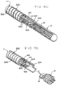
- FIGs. 3A through 3C illustrate component parts of an example delivery system with the sleeve 500 illustrated in FIG. 3A , the loop wire 400a illustrated in FIG. 3B , and an assembly including the proximal tube 100, coiled section 200b, and distal tube 300 in FIG. 3C .
- the winding of the coiled section 200a has a substantially square shaped cross section while, in FIG. 3C , the winding of the coiled section 200b has a substantially circular cross section.
- the coiled wire can be formed of a substantially linear wire that is wound in a coil shape and/or a hypotube that is laser cut in a spiral pattern. If the coiled wire is formed from a laser cut hypotube, the spiral can be absent interference cuts connecting windings in the coil so as to provide a more flexible coil.
- a coiled section formed from a laser cut hypotube can have a substantially square shaped cross section as illustrated by the coiled section 200a in FIG. 1 and FIG. 2 .
- a coiled section formed from a linear wire wound into a coil shape can have a substantially circular cross section as illustrated by the coiled section 200b in FIG. 3C .
- the proximal hypotube 100 can include a flexible section 106 having material removed to increase flexibility of the flexible section 106.
- the flexible section 106 can be cut in a spiral pattern.
- the spiral pattern of the flexible section 106 can lack interference cuts connecting windings within the spiral.
- the proximal attachment end 406a of the loop wire 400 can be attached to the proximal tube 100 in the proximal direction relative to the flexible section 106 of the proximal tube 100.
- the loop wire 400a can thereby inhibit elongation of the flexible section 106 of the proximal tube 100 and coiled section 200b.
- the sleeve 500 can cover at least a portion of the flexible section 106 to inhibit deformation of the flexible section and/or reduce friction with vasculature and the flexible section 106 during intravascular navigation. In some examples, the sleeve 500 can cover about 10 cm of the proximal tube 100 approximate and/or including the distal end 104 of the proximal tube 100.
- the coiled section 200a, 200b can be formed separately from the proximal hypotube 100 and/or the distal hypotube 300.
- the separately formed coiled section 200a, 200b can be affixed with welds 712, 714 or other appropriate attachment to the proximal tube 100 and/or the distal tube 300.
- at least a portion of the coiled section can be formed from a spiral laser cut portion of a hypotube.
- a separately formed coiled section 200b can be made more flexible compared to a spiral cut tube 200a by selecting a wire with a particular cross section (e.g. circular) with a particular diameter D, or by selecting a wire with material properties to increase flexibility.
- a laser cut portion 200a can be more easily fabricated by cutting a single hypotube to form the proximal tube 100, coiled section 200a, and distal hypotube 300, reducing or eliminating welds 712, 714 or other attachments.
- the wire of the coil 200a, 200b can have a diameter D or width W measuring within a range including about 0.8 mils and 5 mils (about 20 ⁇ m to about 130 ⁇ m).
- the coiled section can be formed primarily of a non-radiopaque material such as steel and can include a radiopaque section 216 made of a radiopaque material such as platinum and/or tungsten.
- the radiopaque section 216 can be positioned between a proximal, non-radiopaque section of the coil 212 and a distal, non-radiopaque section of the coil 214.
- the radiopaque section 216 can be positioned a predetermined distance from a distal end 304 of the delivery member 10a, 10b so that a physician can readily visualize the placement of the distal portion of the delivery member during a treatment procedure.
- the proximal section 212, radiopaque section 216, and distal section 214 can be concentrically welded.
- the coiled section 200a, 200b can be surrounded by a flexible sleeve or fused jacket 500, referred generically herein as a "sleeve".
- the sleeve can inhibit the coil 200a, 200b from expanding radially and/or from engaging vascular walls during navigation.
- the sleeve 500 can include a polymer.
- the polymer can include additives to increase the lubricity of the sleeve 500 so that the sleeve can easily slide through a body vessel.
- the sleeve 500 can have a wall thickness T measuring within a range including about 0.5 mils and about 2 mils (about 0.01 mm to about 0.05 mm).
- the sleeve 500 can further be coated with a hydrophilic coating to further minimize friction during intravascular navigation.
- the sleeve 500 can be fused or glued to the coil 200a, 200b, the proximal hypotube 100, and/or the distal hypotube 300.
- the proximal tube 100 can extend a majority of the length of the delivery member 10a, 10b with the coiled section 200a, 200b and distal tube 300 forming a length L sufficient to absorb a majority of push-back that can occur during placement of an implant at a treatment site.
- the length L can include the distal tube 300, coiled section 200a, 200b, and the flexible section 106 of the proximal tube, measured from the proximal end of the flexible section 106 to the distal end of the distal tube 300.
- the length L can measure between about 30 cm and about 50 cm, or more specifically, about 40 cm.
- proximal hypotube 100 can be sufficiently stiff over a majority of its length to resist kinking while being pushed through the microcatheter.
- the flexible coil 200a, 200b and distal compressible tube 300 can each be sufficiently flexible to reduce the effects of push-back when an implant 12 is being placed in an aneurysm. Because the flexible coil 200a, 200b need not be compressibly resilient, the flexible coil can have greater flexibility than the distal compressible tube.
- the flexible coil 200a, 200b and sleeve 500 assembly can be about 25% more flexible than the distal compressible tube 300. In some examples, the flexible coil 200a, 200b and sleeve 500 assembly can be about 20 times more flexible than the proximal hypotube 100. Flexibility can be measured using a three-point bend test or other appropriate test as would be appreciated and understood by a person of ordinary skill in the art. Generally, a three-point bend test can be performed by fixing a tube portion at two points and applying a force in between the two points. Flexibility can be quantified by a length of displacement of the tube portion for a predetermined force and/or by a magnitude of force to displace the tube by a predetermined length.
- FIGs. 1, 2 , and 4A each illustrate an implant 12 secured to a delivery member 10a, 10b, 10 by a mechanical engagement system including the loop wire 400a, 400b, 400 and an inner elongated member 140 that can be manipulated at the proximal end by a physician to deploy the implant 12.
- a wire or inner elongated member is referred to herein generically as a "pull wire" 140.
- the combination of the coil 200a, 200b, sleeve 500, and loop wire 400, 400a, 400b can provide a highly flexible distal portion of a delivery member 10, 10a, 10b suitable for navigating tortuous anatomy, including neurovascular blood vessels.
- the loop wire 400, 400a, 400b can support the coil 200a, 200b to prevent the coil 200a, 200b from significantly elongating during navigation of a blood vessel, thereby reducing tension on the pull wire's 140 engagement to the loop opening 405 and reducing the likelihood of premature deployment of an attached medical treatment device 12.
- the distal tube 300 can include a compressible portion 306.
- the compressible portion 306 can be axially adjustable between an elongated condition and a compressed condition.
- the compressed portion 306 can be formed from a spiral-cut portion of the tube 300, formed by a laser cutting operation. Additionally, or alternatively, the compressible portion can be formed of a wound wire, spiral ribbon, or other arrangement allowing axial adjustment according to the present invention.
- the compressible portion 306 is in the elongated condition at rest and automatically or resiliently returns to the elongated condition from a compressed condition, unless otherwise constrained.
- FIGs. 4A through 4D are a time sequence set of illustrations depicting release of a medical device (e.g. implant) 12 from a delivery member 10.
- the delivery member 10 can be configured such as illustrated in FIGs. 1 through 3C and otherwise described herein.
- FIG. 4A illustrates an engagement system including the loop wire 400 and pull wire 140 locked into a locking portion 18 of the medical device 12.
- the compressible portion 306 of the distal tube 300 can be compressed and the loop wire 400 opening 405 at a distal end 404 of the loop wire 400 can be placed through the locking portion 18.
- FIG. 4B illustrates the pull wire 140 being drawn proximally to begin the release sequence for the medical device 12.
- FIG. 4C illustrates the instant the distal end 144 of the pull wire 140 exits the opening 405 and the pull wire 140 is pulled free of the loop wire 400.
- the distal end 404 of the loop wire 400 falls away and exits the locking portion 18.
- FIG. 4D illustrates the end of the release sequence.
- the compressible portion 306 has extended/returned to its original shape and "sprung” forward.
- An elastic force E is imparted by the distal end 304 of the distal tube 300 to the medical device 12 to "push" it away to ensure a clean separation and delivery of the medical device 12.
- the compressible portion 306 can have a difference in length (distance of compression) when measured in the compressed configuration and the original, uncompressed configuration of about 0.5 mm to about 0.75 mm. Greater elastic force E can be achieved by using a greater distance of compression.
- the distance of compression can be determined by the sizing of the loop wire 400, the shape of the locking portion 18, and the shape of the distal end 304 of the distal tube 300.
- FIG. 5 is a flow diagram outlining example method steps of a method 800 for treating an aneurysm.
- Steps 804, 808, 812, 816, 820, and 824 are generally directed toward designing, constructing, or configuring a delivery system such as an example system presented herein, a variation thereof, and alternative implant delivery systems as would be appreciated and understood by a person of ordinary skill in the art.
- Steps 828, 832, 836, and 840 are directed toward delivering and deploying an implant with the delivery system designed, constructed, or configured according to one or more of the preceding method steps.
- a proximal tube, coiled wire, and a compressible distal tube can be connected such that the assembly is substantially tubular and has a contiguous lumen extending through the assembled sections.
- the proximal tube, the coiled wire, and the compressible distal tube can each respectively be a proximal tube 100, support coil 200a, 200b, and distal hypotube 300 such as described and/or illustrated herein, a variation thereof, or an alternative as would be appreciated and understood by a person of ordinary skill in the art.
- a sleeve can be positioned along the coiled wire.
- the sleeve can be a sleeve 500 such as described and/or illustrated herein, a variation thereof, or an alternative as would be appreciated and understood by a person of ordinary skill in the art.
- the sleeve can be positioned to surround a portion of the length of the coiled wire, or the entire length of the coiled wire.
- the sleeve can also be positioned to extend to cover a respective portion of one or both of the proximal tube and the distal tube.
- a loop wire can be affixed to the proximal tube.
- the loop wire can be a loop wire 400, 400a, 400b such as described and/or illustrated herein, a variation thereof, or an alternative as would be appreciated and understood by a person of ordinary skill in the art.
- the loop wire can have two ends, at least one of the two ends can be affixed to the proximal tube in step 812, and a loop opening can be defined as a bend in the loop wire between the two ends.
- An end not affixed to the proximal tube in step 812 can be affixed to the delivery member at the distal tube or other location.
- the loop wire can have a single end that is affixed to the proximal tube in step 812 and a loop opening formed at an opposite end of the loop wire.
- the loop opening of the loop wire can be positioned at a distal end of the distal tube.
- the loop opening can be positioned as described and/or illustrated herein or otherwise positioned to facilitate attachment of an implant at the distal end of the distal tube.
- step 820 the compressible distal tube can be compressed.
- an implant can be secured to the compressed distal tube by passing the loop opening through an engagement feature (locking portion or opening) on the implant and passing a pull wire through the loop opening.
- the implant can be delivered to a treatment site.
- the implant can be an implant 10, 10a, 10b as described and/or illustrated herein, a variation thereof, or an alternative medical treatment device as would be appreciated and understood by a person of ordinary skill in the art.
- the implant can be delivered by means known to a person of ordinary skill in the art.
- the treatment site can be an intravascular treatment site such as an aneurysm or lesion.
- the implant can be delivered through a catheter positioned intravascularly.
- a portion of a delivery system e.g. the proximal tube
- the implant can be attached at the distal end of the delivery system and pushed by the delivery system as the delivery system is pushed by the physician further into the catheter.
- the sleeve can inhibit radial expansion of the coil as the implant is being delivered to the treatment site.
- the sleeve can inhibit radial expansion of the coil by means described herein, variations thereof, or alternatives as would be appreciated and understood by a person of ordinary skill in the art.
- step 836 longitudinal expansion of the coiled wire can be inhibited with the loop wire during delivery of the implant.
- the loop wire can be stretch resistant and be positioned such that the loop wire does not significantly elongate during delivery of the implant.
- the implant can be released by retracting the pull wire.
- the distal end of the pull wire can move proximally to exit the loop opening. Once the loop wire is no longer held in place by the pull wire, the loop wire can retract from the locking portion on the implant, thereby releasing the implant.
- the terms “about” or “approximately” for any numerical values or ranges indicate a suitable dimensional tolerance that allows the part or collection of components to function for its intended purpose as described herein. More specifically, “about” or “approximately” may refer to the range of values ⁇ 20% of the recited value, e.g. "about 90%” may refer to the range of values from 71% to 99%.
Landscapes
- Health & Medical Sciences (AREA)
- Life Sciences & Earth Sciences (AREA)
- Surgery (AREA)
- Biomedical Technology (AREA)
- Engineering & Computer Science (AREA)
- Animal Behavior & Ethology (AREA)
- General Health & Medical Sciences (AREA)
- Veterinary Medicine (AREA)
- Heart & Thoracic Surgery (AREA)
- Public Health (AREA)
- Vascular Medicine (AREA)
- Medical Informatics (AREA)
- Molecular Biology (AREA)
- Nuclear Medicine, Radiotherapy & Molecular Imaging (AREA)
- Reproductive Health (AREA)
- Anesthesiology (AREA)
- Biophysics (AREA)
- Pulmonology (AREA)
- Hematology (AREA)
- Neurosurgery (AREA)
- Cardiology (AREA)
- Oral & Maxillofacial Surgery (AREA)
- Transplantation (AREA)
- Surgical Instruments (AREA)
- Media Introduction/Drainage Providing Device (AREA)
Claims (17)
- Abgabeelement (10a, 10b) zum Abgeben einer implantierbaren medizinischen Vorrichtung an eine Zielstelle eines Körpergefäßes, das Abgabeelement umfassend:einen proximalen Hyposchlauch (100);eine flexible Spule (200a, 200b), die sich von einem distalen Ende des proximalen Hyposchlauchs (100) erstreckt;einen komprimierbaren distalen Hyposchlauch (300), der sich von einem distalen Ende der flexiblen Spule (200a, 200b) erstreckt;ein Lumen (608), das sich von einem proximalen Ende des proximalen Hyposchlauchs (100) durch den proximalen Hyposchlauch (100) hindurch, durch die flexible Spule (200a, 200b) hindurch, durch den komprimierbaren distalen Hyposchlauch (300) hindurch und zu einem distalen Ende (304) des komprimierbaren distalen Hyposchlauchs (300) erstreckt;eine Hülse (500), die sich über einen Großteil der flexiblen Spule (200a, 200b) erstreckt,wobei die Hülse (500) wirksam ist, um eine radiale Ausdehnung der flexiblen Spule (200a, 200b) zu verhindern; undeinen Schleifendraht (400a, 400b), umfassend ein erstes Ende (406a), das an dem proximalen Hyposchlauch (100) angebracht ist, und umfassend eine Schleifenöffnung (405), die in der Nähe eines distalen Endes (304) des komprimierbaren distalen Hyposchlauchs (300) positioniert ist,wobei der Schleifendraht (400a, 400b) wirksam ist, um eine Längsdehnung der flexiblen Spule (200a, 200b) zu verhindern; das Abgabeelement ferner umfassend:einen Zugdraht (140), der sich durch das Lumen (608) hindurch erstreckt,wobei der Schleifendraht (400a, 400b) und der Zugdraht (140) positioniert sind, um die implantierbare medizinische Vorrichtung an dem Abgabesystem zu befestigen, undwobei der Schleifendraht (400a, 400b) und der Zugdraht (140) bewegbar sind, um die implantierbare medizinische Vorrichtung aus dem Abgabesystem freizugeben, wobei der Schleifendraht (400a, 400b) dehnungsbeständig ist, undwobei der Schleifendraht (400a, 400b) unter Spannung steht, wenn die implantierbare medizinische Vorrichtung an dem Abgabesystem befestigt ist.
- Abgabeelement nach Anspruch 1,
wobei die flexible Spule (200a, 200b) flexibler als der proximale Hyposchlauch (100) ist. - Abgabeelement nach Anspruch 1 oder 2, wobei die flexible Spule (200a, 200b) umfasst:eine nicht röntgendichte proximale Spule (212), die sich von einem proximalen Ende der flexiblen Spule erstreckt;eine nicht röntgendichte distale Spule (214), die sich von dem distalen Ende der flexiblen Spule erstreckt; undeine röntgendichte zentrale Spule (216), die sich zwischen der nicht röntgendichten proximalen Spule (212) und der nicht röntgendichten distalen Spule (214) erstreckt.
- Abgabeelement nach einem der Ansprüche 1 bis 3, wobei die flexible Spule (200a, 200b) umfasst:
einen Draht, der gewickelt ist, um die flexible Spule (200a, 200b) auszubilden und der einen Abschnitt des Lumens (608) definiert, der Draht umfassend einen Durchmesser von etwa 0,0008 Zoll bis etwa 0,005 Zoll (etwa 20 µm bis etwa 130 µm). - Abgabeelement nach Anspruch 4, wobei der Draht einen im Wesentlichen kreisförmigen Querschnitt umfasst.
- Abgabeelement nach einem der Ansprüche 1 bis 5, ferner umfassend:eine distale Abschnittslänge, die von dem distalen Ende des komprimierbaren distalen Hyposchlauchs (300) bis zu einem proximalen Ende der flexiblen Spule (200a, 200b) messbar ist,wobei die Länge des distalen Abschnitts etwa 40 cm beträgt.
- Abgabeelement nach einem der Ansprüche 1 bis 6, wobei die Hülse (500) mindestens einen Großteil einer Außenoberfläche der flexiblen Spule (200a, 200b) bedeckt.
- Abgabeelement nach einem der vorstehenden Ansprüche,wobei der komprimierbare distale Hyposchlauch (300) einen Spiralschnitt umfasst,wobei der komprimierbare distale Hyposchlauch (300) aufgrund einer Spannung in dem Schleifendraht (400a, 400b) komprimiert wird, wenn die implantierbare medizinische Vorrichtung an dem komprimierbaren distalen Hyposchlauch (300) befestigt wird, undwobei der komprimierbare distale Hyposchlauch (300) bewegbar ist, um sich bei einer Bewegung des Schleifendrahts (400a, 400b) und des Zugdrahts (140) zu dekomprimieren, um die implantierbare medizinische Vorrichtung freizugeben.
- Abgabeelement nach einem der vorstehenden Ansprüche,wobei die Schleifenöffnung (405) durch eine Vorrichtungsöffnung in der implantierbaren medizinischen Vorrichtung hindurch erstreckt wird,wobei der Zugdraht (140) durch die Schleifenöffnung (405) erstreckt wird,wobei der Zugdraht (140) proximal zurückziehbar ist, um aus der Schleifenöffnung (405) herauszutreten, undwobei die Schleifenöffnung (405) bewegbar ist, um aus der Vorrichtungsöffnung in der implantierbaren medizinischen Vorrichtung herauszutreten, wenn die Schleifenöffnung (405) nicht durch den Zugdraht (140) blockiert ist.
- Verfahren zum Herstellen des Abgabeelements nach einem der Ansprüche 1 bis 9, umfassend:Verbinden eines distalen Endes (104) eines proximalen Schlauchs (100) mit einem proximalen Ende (202) eines gewickelten Drahts (200a, 200b);Verbinden eines distalen Endes (204) des gewickelten Drahts (200a, 200b) mit einem proximalen Ende (302) eines komprimierbaren distalen Schlauchs (300);Verbinden des proximalen Schlauchs (100), des gewickelten Drahts (200a, 200b) und des komprimierbaren distalen Schlauchs (300), um einen Abgabeschlauch bereitzustellen, umfassend ein Lumen (608), das sich durch den proximalen Schlauch (100), den gewickelten Draht (200a, 200b) und den komprimierbaren distalen Schlauch (300) hindurch erstreckt;Positionieren einer Hülse (500) entlang eines Großteils des gewickelten Drahts (200a, 200b);Verhindern der radialen Ausdehnung des gewickelten Drahts (200a, 200b) mit der Hülse (500);Anbringen eines Schleifendrahts (400a, 400b) an dem proximalen Schlauch (100);Positionieren einer Schleifenöffnung in dem Schleifendraht (400a, 400b) in der Nähe eines distalen Endes des distalen Schlauchs, während der Schleifendraht an dem proximalen Schlauch derart angebracht ist, dass der Schleifendraht durch den gewickelten Draht hindurch erstreckt wird und positioniert ist, um eine implantierbare medizinische Vorrichtung an dem Abgabesystem zu befestigen und eine Längsdehnung des gewickelten Drahts mit dem Schleifendraht (400a, 400b) zu verhindern, wenn die implantierbare medizinische Vorrichtung an dem Abgabesystem befestigt ist und der Schleifendraht (400a, 400b) unter Spannung steht.
- Verfahren nach Anspruch 10, ferner umfassend:
Auswählen des gewickelten Drahts (200a, 200b) und der Hülse (500) derart, dass, wenn die Hülse (500) entlang des Großteils des gewickelten Drahts (200a, 200b) positioniert ist, der gewickelte Draht und die Hülse flexibler als sowohl der proximale Hyposchlauch als auch der komprimierbare distale Schlauch sind. - Verfahren nach Anspruch 10 oder 11, ferner umfassend:
Positionieren eines röntgendichten gewickelten Bereichs (216) in dem gewickelten Draht (200a, 200b). - Verfahren nach einem der Ansprüche 10 bis 12, ferner umfassend:
derartiges Auswählen des gewickelten Drahts (200a, 200b), dass der gewickelte Draht (200a, 200b) einen Draht umfasst, der gewickelt ist, um einen Abschnitt des Lumens (608) zu definieren, und der Draht einen Durchmesser von etwa 0,0008 Zoll bis etwa 0,005 Zoll (etwa 20 µm bis etwa 130 µm) umfasst. - Verfahren nach einem der Ansprüche 10 bis 13, ferner umfassend:
Bemessen des gewickelten Drahts (200a, 200b) und des komprimierbaren distalen Schlauchs (300), um eine Länge zu umfassen, die von dem distalen Ende des distalen Schlauchs (300) zu dem proximalen Ende des gewickelten Drahts (200a, 200b) derart messbar ist, dass die Länge von etwa 40 cm bis etwa 50 cm misst. - Verfahren nach einem der Ansprüche 10 bis 14, ferner umfassend:
Befestigen eines intravaskulären Implantats (12) an dem Abgabeschlauch wie folgt:Strecken eines Zugdrahts durch das Lumen hindurch,Strecken der Schleifenöffnung (405) durch einen Verriegelungsabschnitt des intravaskulären Implantats (12) hindurch undStrecken eines distalen Endes des Zugdrahts (140) durch die Schleifenöffnung (405) hindurch. - Verfahren nach einem der Ansprüche 10 bis 15, ferner umfassend:Komprimieren des komprimierbaren distalen Schlauchs (300);Positionieren der Schleifenöffnung (405) in der Nähe des distalen Endes des distalen Schlauchs (300), während der distale Schlauch komprimiert ist und während der Schleifendraht (400a, 400b) an dem proximalen Schlauch angebracht ist;Befestigen, mit dem Schleifendraht (400a, 400b), eines Implantats an dem Abgabeschlauch, während der distale Schlauch (300) komprimiert wird und während der Schleifendraht an dem proximalen Schlauch angebracht ist.
- Verfahren nach Anspruch 16, ferner umfassend:Aufrechterhalten, über Spannung in dem Schleifendraht (405), einer Kompression des distalen Schlauchs (300);Verhindern, über Spannung in dem Schleifendraht (400a, 400b), der Längsausdehnung des gewickelten Drahts (200a, 200b), während der distale Schlauch komprimiert wird; undVerhindern der radialen Ausdehnung des gewickelten Drahts (200a, 200b) mit der Hülse (500), während der distale Schlauch komprimiert wird.
Applications Claiming Priority (1)
| Application Number | Priority Date | Filing Date | Title |
|---|---|---|---|
| US16/592,320 US11426174B2 (en) | 2019-10-03 | 2019-10-03 | Medical device delivery member with flexible stretch resistant mechanical release |
Publications (3)
| Publication Number | Publication Date |
|---|---|
| EP3799803A1 EP3799803A1 (de) | 2021-04-07 |
| EP3799803C0 EP3799803C0 (de) | 2025-05-21 |
| EP3799803B1 true EP3799803B1 (de) | 2025-05-21 |
Family
ID=72744674
Family Applications (1)
| Application Number | Title | Priority Date | Filing Date |
|---|---|---|---|
| EP20199892.9A Active EP3799803B1 (de) | 2019-10-03 | 2020-10-02 | Abgabeelement einer medizinischen vorrichtung mit flexibler dehnungsbeständiger mechanischer freigabe |
Country Status (6)
| Country | Link |
|---|---|
| US (2) | US11426174B2 (de) |
| EP (1) | EP3799803B1 (de) |
| JP (1) | JP7593549B2 (de) |
| KR (1) | KR102875171B1 (de) |
| CN (1) | CN112603431A (de) |
| ES (1) | ES3032344T3 (de) |
Families Citing this family (16)
| Publication number | Priority date | Publication date | Assignee | Title |
|---|---|---|---|---|
| US9918718B2 (en) | 2014-08-08 | 2018-03-20 | DePuy Synthes Products, Inc. | Embolic coil delivery system with retractable mechanical release mechanism |
| US10806462B2 (en) | 2017-12-21 | 2020-10-20 | DePuy Synthes Products, Inc. | Implantable medical device detachment system with split tube and cylindrical coupling |
| US11253265B2 (en) | 2019-06-18 | 2022-02-22 | DePuy Synthes Products, Inc. | Pull wire detachment for intravascular devices |
| US11426174B2 (en) | 2019-10-03 | 2022-08-30 | DePuy Synthes Products, Inc. | Medical device delivery member with flexible stretch resistant mechanical release |
| US11207494B2 (en) | 2019-07-03 | 2021-12-28 | DePuy Synthes Products, Inc. | Medical device delivery member with flexible stretch resistant distal portion |
| US11951026B2 (en) | 2020-06-30 | 2024-04-09 | DePuy Synthes Products, Inc. | Implantable medical device detachment system with flexible braid section |
| CN115942908A (zh) * | 2020-08-21 | 2023-04-07 | 形状记忆医疗公司 | 用于经导管装置的机械分离系统 |
| US11937824B2 (en) | 2021-12-30 | 2024-03-26 | DePuy Synthes Products, Inc. | Implant detachment systems with a modified pull wire |
| US11844490B2 (en) | 2021-12-30 | 2023-12-19 | DePuy Synthes Products, Inc. | Suture linkage for inhibiting premature embolic implant deployment |
| US12508032B2 (en) * | 2021-12-31 | 2025-12-30 | DePuy Synthes Products, Inc. | Medical device delivery systems with twisting loop wires |
| US12011171B2 (en) | 2022-01-06 | 2024-06-18 | DePuy Synthes Products, Inc. | Systems and methods for inhibiting premature embolic implant deployment |
| US12471924B2 (en) | 2022-03-02 | 2025-11-18 | DePuy Synthes Products, Inc. | Flexible feature for embolic implant deployment |
| US11937825B2 (en) | 2022-03-02 | 2024-03-26 | DePuy Synthes Products, Inc. | Hook wire for preventing premature embolic implant detachment |
| US12137915B2 (en) * | 2022-03-03 | 2024-11-12 | DePuy Synthes Products, Inc. | Elongating wires for inhibiting premature implant detachment |
| US11937826B2 (en) | 2022-03-14 | 2024-03-26 | DePuy Synthes Products, Inc. | Proximal link wire for preventing premature implant detachment |
| US12402886B2 (en) | 2022-06-23 | 2025-09-02 | DePuy Synthes Products, Inc. | Detachment indicator for implant deployment |
Citations (1)
| Publication number | Priority date | Publication date | Assignee | Title |
|---|---|---|---|---|
| EP3795097A1 (de) * | 2019-09-17 | 2021-03-24 | DePuy Synthes Products, Inc. | Proximales embolisches spulenverbindungselement und dehnungsbeständige faser |
Family Cites Families (298)
| Publication number | Priority date | Publication date | Assignee | Title |
|---|---|---|---|---|
| US2220203A (en) | 1939-02-27 | 1940-11-05 | William L Branin | Cable clamp |
| US3429408A (en) | 1967-04-25 | 1969-02-25 | Associated Spring Corp | Actuator sleeves for spring clutch |
| US4858810A (en) | 1987-04-30 | 1989-08-22 | Heart Technology, Inc. | Quick acting pin vise for use with angiographic guidewires |
| US5484409A (en) | 1989-08-25 | 1996-01-16 | Scimed Life Systems, Inc. | Intravascular catheter and method for use thereof |
| US5122136A (en) | 1990-03-13 | 1992-06-16 | The Regents Of The University Of California | Endovascular electrolytically detachable guidewire tip for the electroformation of thrombus in arteries, veins, aneurysms, vascular malformations and arteriovenous fistulas |
| US5108407A (en) | 1990-06-08 | 1992-04-28 | Rush-Presbyterian St. Luke's Medical Center | Method and apparatus for placement of an embolic coil |
| US5234437A (en) | 1991-12-12 | 1993-08-10 | Target Therapeutics, Inc. | Detachable pusher-vasoocclusion coil assembly with threaded coupling |
| USD329698S (en) | 1991-12-13 | 1992-09-22 | Scimed Life Systems, Inc. | Clamp for gripping a guide wire or hollow tube for a catheter |
| US5636639A (en) | 1992-02-18 | 1997-06-10 | Symbiosis Corporation | Endoscopic multiple sample bioptome with enhanced biting action |
| SE9201295D0 (sv) | 1992-04-24 | 1992-04-24 | Siemens Elema Ab | Styrbar elektrodanordning |
| US5263964A (en) | 1992-05-06 | 1993-11-23 | Coil Partners Ltd. | Coaxial traction detachment apparatus and method |
| US5536248A (en) | 1992-05-11 | 1996-07-16 | Arrow Precision Products, Inc. | Method and apparatus for electrosurgically obtaining access to the biliary tree and placing a stent therein |
| US5250071A (en) | 1992-09-22 | 1993-10-05 | Target Therapeutics, Inc. | Detachable embolic coil assembly using interlocking clasps and method of use |
| US5350397A (en) | 1992-11-13 | 1994-09-27 | Target Therapeutics, Inc. | Axially detachable embolic coil assembly |
| US5382259A (en) | 1992-10-26 | 1995-01-17 | Target Therapeutics, Inc. | Vasoocclusion coil with attached tubular woven or braided fibrous covering |
| US5334210A (en) | 1993-04-09 | 1994-08-02 | Cook Incorporated | Vascular occlusion assembly |
| US5925059A (en) | 1993-04-19 | 1999-07-20 | Target Therapeutics, Inc. | Detachable embolic coil assembly |
| US5569221A (en) | 1994-07-07 | 1996-10-29 | Ep Technologies, Inc. | Catheter component bond and method |
| CA2203122A1 (en) | 1994-10-20 | 1996-05-02 | Mordechay Beyar | Cystoscope delivery system |
| US5645558A (en) * | 1995-04-20 | 1997-07-08 | Medical University Of South Carolina | Anatomically shaped vasoocclusive device and method of making the same |
| US6273404B1 (en) | 1995-06-05 | 2001-08-14 | Scimed Life Systems, Inc. | Method of making monolithic hub and strain relief |
| US6168622B1 (en) | 1996-01-24 | 2001-01-02 | Microvena Corporation | Method and apparatus for occluding aneurysms |
| US5899935A (en) | 1997-08-04 | 1999-05-04 | Schneider (Usa) Inc. | Balloon expandable braided stent with restraint |
| US6203547B1 (en) | 1997-12-19 | 2001-03-20 | Target Therapeutics, Inc. | Vaso-occlusion apparatus having a manipulable mechanical detachment joint and a method for using the apparatus |
| US6113622A (en) | 1998-03-10 | 2000-09-05 | Cordis Corporation | Embolic coil hydraulic deployment system |
| US6835185B2 (en) | 1998-12-21 | 2004-12-28 | Micrus Corporation | Intravascular device deployment mechanism incorporating mechanical detachment |
| US6391037B1 (en) | 2000-03-02 | 2002-05-21 | Prodesco, Inc. | Bag for use in the intravascular treatment of saccular aneurysms |
| US6723108B1 (en) | 2000-09-18 | 2004-04-20 | Cordis Neurovascular, Inc | Foam matrix embolization device |
| US6623504B2 (en) | 2000-12-08 | 2003-09-23 | Scimed Life Systems, Inc. | Balloon catheter with radiopaque distal tip |
| DE60224502T2 (de) | 2001-01-10 | 2008-12-24 | Cordis Neurovascular, Inc., Miami Lakes | System zum Einführen einer Emboliespirale |
| US6537300B2 (en) | 2001-05-30 | 2003-03-25 | Scimed Life Systems, Inc. | Implantable obstruction device for septal defects |
| US6454780B1 (en) | 2001-06-21 | 2002-09-24 | Scimed Life Systems, Inc. | Aneurysm neck obstruction device |
| ES2274984T3 (es) | 2001-07-05 | 2007-06-01 | Precision Vascular Systems, Inc. | Dispositivo medico de punta blanda que puede someterse a torsion y metodo para conformarlo. |
| US8252040B2 (en) | 2001-07-20 | 2012-08-28 | Microvention, Inc. | Aneurysm treatment device and method of use |
| US8715312B2 (en) | 2001-07-20 | 2014-05-06 | Microvention, Inc. | Aneurysm treatment device and method of use |
| US6811561B2 (en) | 2001-11-15 | 2004-11-02 | Cordis Neurovascular, Inc. | Small diameter deployment system with improved headpiece |
| DE60213457T2 (de) | 2001-12-03 | 2007-10-18 | Ekos Corp., Bothell | Ultraschallkatheter für kleine gefässe |
| JP4328209B2 (ja) | 2002-01-25 | 2009-09-09 | アトリテック, インコーポレイテッド | 心耳血液ろ過システム |
| US20030195553A1 (en) | 2002-04-12 | 2003-10-16 | Scimed Life Systems, Inc. | System and method for retaining vaso-occlusive devices within an aneurysm |
| US7608058B2 (en) | 2002-07-23 | 2009-10-27 | Micrus Corporation | Stretch resistant therapeutic device |
| US8425549B2 (en) | 2002-07-23 | 2013-04-23 | Reverse Medical Corporation | Systems and methods for removing obstructive matter from body lumens and treating vascular defects |
| US7208003B2 (en) | 2002-09-20 | 2007-04-24 | Cordis Neurovascular, Inc. | Reattachable introducer for a medical device deployment system |
| FR2853521B1 (fr) | 2003-04-10 | 2005-12-02 | Claude Mialhe | Dispositif de dilatation d'un vaisseau et introducteur d'implant vasculaire |
| US7371228B2 (en) | 2003-09-19 | 2008-05-13 | Medtronic Vascular, Inc. | Delivery of therapeutics to treat aneurysms |
| US8182544B2 (en) | 2003-10-08 | 2012-05-22 | Codman & Shurtleff, Inc. | Method for placing a medical agent into a vessel of the body |
| US9308382B2 (en) | 2004-06-10 | 2016-04-12 | Medtronic Urinary Solutions, Inc. | Implantable pulse generator systems and methods for providing functional and/or therapeutic stimulation of muscles and/or nerves and/or central nervous system tissue |
| US20060025801A1 (en) | 2004-07-30 | 2006-02-02 | Robert Lulo | Embolic device deployment system with filament release |
| US9655633B2 (en) | 2004-09-10 | 2017-05-23 | Penumbra, Inc. | System and method for treating ischemic stroke |
| WO2006052322A2 (en) | 2004-09-22 | 2006-05-18 | Guterman Lee R | Cranial aneurysm treatment arrangement |
| US20060089637A1 (en) | 2004-10-14 | 2006-04-27 | Werneth Randell L | Ablation catheter |
| EP1656963B1 (de) | 2004-11-10 | 2007-11-21 | Creganna Technologies Limited | Einführkatheteranordnung für stents |
| US8562672B2 (en) | 2004-11-19 | 2013-10-22 | Medtronic, Inc. | Apparatus for treatment of cardiac valves and method of its manufacture |
| US20060116714A1 (en) | 2004-11-26 | 2006-06-01 | Ivan Sepetka | Coupling and release devices and methods for their assembly and use |
| US8425550B2 (en) | 2004-12-01 | 2013-04-23 | Boston Scientific Scimed, Inc. | Embolic coils |
| US7608089B2 (en) | 2004-12-22 | 2009-10-27 | Boston Scientific Scimed, Inc. | Vaso-occlusive device having pivotable coupling |
| US20060206139A1 (en) | 2005-01-19 | 2006-09-14 | Tekulve Kurt J | Vascular occlusion device |
| WO2006124549A1 (en) | 2005-05-12 | 2006-11-23 | Ev3, Inc. | Implant delivery system with interlocked rx port orientation |
| US20060276825A1 (en) | 2005-06-02 | 2006-12-07 | Vladimir Mitelberg | Stretch resistant embolic coil delivery system with mechanical release mechanism |
| US20060276830A1 (en) | 2005-06-02 | 2006-12-07 | Keith Balgobin | Stretch resistant embolic coil delivery system with mechanical release mechanism |
| US7371252B2 (en) | 2005-06-02 | 2008-05-13 | Cordis Neurovascular, Inc. | Stretch resistant embolic coil delivery system with mechanical release mechanism |
| US7708755B2 (en) | 2005-06-02 | 2010-05-04 | Codman & Shurtleff Inc. | Stretch resistant embolic coil delivery system with combined mechanical and pressure release mechanism |
| US7811305B2 (en) | 2005-06-02 | 2010-10-12 | Codman & Shurtleff, Inc. | Stretch resistant embolic coil delivery system with spring release mechanism |
| US7371251B2 (en) | 2005-06-02 | 2008-05-13 | Cordis Neurovascular, Inc. | Stretch resistant embolic coil delivery system with mechanical release mechanism |
| US7819892B2 (en) | 2005-06-02 | 2010-10-26 | Codman & Shurtleff, Inc. | Embolic coil delivery system with spring wire release mechanism |
| US20060276826A1 (en) | 2005-06-02 | 2006-12-07 | Vladimir Mitelberg | Stretch resistant embolic coil delivery system with mechanical release mechanism |
| US7819891B2 (en) | 2005-06-02 | 2010-10-26 | Codman & Shurtleff, Inc. | Stretch resistant embolic coil delivery system with spring release mechanism |
| US7708754B2 (en) | 2005-06-02 | 2010-05-04 | Codman & Shurtleff, Pc | Stretch resistant embolic coil delivery system with mechanical release mechanism |
| US7367987B2 (en) | 2005-06-02 | 2008-05-06 | Cordis Neurovascular, Inc. | Stretch resistant embolic coil delivery system with mechanical release mechanism |
| US20060276833A1 (en) | 2005-06-02 | 2006-12-07 | Keith Balgobin | Stretch resistant embolic coil delivery system with spring assisted release mechanism |
| US7799052B2 (en) | 2005-06-02 | 2010-09-21 | Codman & Shurtleff, Inc. | Stretch resistant embolic coil delivery system with mechanical release mechanism |
| US7985238B2 (en) | 2005-06-02 | 2011-07-26 | Codman & Shurtleff, Inc. | Embolic coil delivery system with spring wire release mechanism |
| US7377932B2 (en) | 2005-06-02 | 2008-05-27 | Cordis Neurovascular, Inc. | Embolic coil delivery system with mechanical release mechanism |
| US9636115B2 (en) | 2005-06-14 | 2017-05-02 | Stryker Corporation | Vaso-occlusive delivery device with kink resistant, flexible distal end |
| AU2006262447A1 (en) | 2005-06-20 | 2007-01-04 | Medtronic Ablation Frontiers Llc | Ablation catheter |
| JP4627687B2 (ja) | 2005-06-20 | 2011-02-09 | Junken Medical株式会社 | ステントの挿入装置 |
| US20070083132A1 (en) | 2005-10-11 | 2007-04-12 | Sharrow James S | Medical device coil |
| EP1973680B1 (de) | 2005-11-17 | 2018-01-10 | Microvention, Inc. | Dreidimensionale komplexspule |
| EP1959873B1 (de) | 2005-12-13 | 2015-05-20 | Codman & Shurtleff, Inc. | Abtrennungsaktuator zur anwendung in systemen zum einsatz medizinischer geräte |
| WO2007070793A2 (en) | 2005-12-13 | 2007-06-21 | Cordis Development Corporation | Two-pitch threaded handle detachment system |
| US7344558B2 (en) | 2006-02-28 | 2008-03-18 | Cordis Development Corporation | Embolic device delivery system |
| US9757260B2 (en) | 2006-03-30 | 2017-09-12 | Medtronic Vascular, Inc. | Prosthesis with guide lumen |
| US7766933B2 (en) | 2006-03-31 | 2010-08-03 | Codman & Shurtleff, Inc. | Stretch resistant design for embolic coils with stabilization bead |
| US9615832B2 (en) | 2006-04-07 | 2017-04-11 | Penumbra, Inc. | Aneurysm occlusion system and method |
| US8777979B2 (en) | 2006-04-17 | 2014-07-15 | Covidien Lp | System and method for mechanically positioning intravascular implants |
| KR20090008347A (ko) | 2006-04-17 | 2009-01-21 | 마이크로 테라퓨틱스 인코포레이티드 | 혈관내 삽입물을 기계적으로 위치설정하는 시스템 및 방법 |
| EP2027729A2 (de) | 2006-06-15 | 2009-02-25 | MicroVention, Inc. | Embolisierungsvorrichtung aus einem dehnbaren polymer |
| US8366720B2 (en) | 2006-07-31 | 2013-02-05 | Codman & Shurtleff, Inc. | Interventional medical device system having an elongation retarding portion and method of using the same |
| US8062325B2 (en) | 2006-07-31 | 2011-11-22 | Codman & Shurtleff, Inc. | Implantable medical device detachment system and methods of using the same |
| US7901444B2 (en) | 2006-09-29 | 2011-03-08 | Codman & Shurtleff, Inc. | Embolic coil delivery system with mechanical release mechanism |
| WO2008064209A1 (en) | 2006-11-20 | 2008-05-29 | Boston Scientific Scimed, Inc. | Mechanically detachable vaso-occlusive device |
| WO2008064205A2 (en) | 2006-11-20 | 2008-05-29 | Boston Scientific Limited | Mechanically detachable vaso-occlusive device |
| US8926650B2 (en) | 2006-11-20 | 2015-01-06 | Boston Scientific Scimed, Inc. | Mechanically detachable vaso-occlusive device |
| US20080281350A1 (en) | 2006-12-13 | 2008-11-13 | Biomerix Corporation | Aneurysm Occlusion Devices |
| US8795316B2 (en) | 2007-04-25 | 2014-08-05 | DePuy Syntheses Products, LLC | Implantable medical device delivery system with a frangible portion and methods of making and using the same |
| US8197442B2 (en) | 2007-04-27 | 2012-06-12 | Codman & Shurtleff, Inc. | Interventional medical device system having a slotted section and radiopaque marker and method of making the same |
| US8864789B2 (en) | 2007-04-27 | 2014-10-21 | DePuy Synthes Products, LLC | Interventional medical device system having a spiral section and radiopaque marker and method of making the same |
| EP2444010B1 (de) | 2007-05-18 | 2017-03-01 | Stryker European Holdings I, LLC | Systeme zum Lösen von medizinischen Implantaten |
| DE102007038446A1 (de) | 2007-08-14 | 2009-02-19 | pfm Produkte für die Medizin AG | Embolisiereinrichtung |
| US20090099592A1 (en) | 2007-10-15 | 2009-04-16 | Boston Scientific Scimed, Inc. | Detachable Interlock Systems and Methods of Use |
| WO2009086208A2 (en) | 2007-12-21 | 2009-07-09 | Microvention, Inc. | Hydrogel filaments for biomedical uses |
| US8974518B2 (en) | 2008-03-25 | 2015-03-10 | Medtronic Vascular, Inc. | Eversible branch stent-graft and deployment method |
| JP5610542B2 (ja) | 2008-04-21 | 2014-10-22 | コヴィディエン リミテッド パートナーシップ | ブレードボール塞栓装置および送達システム |
| US20090276022A1 (en) | 2008-04-30 | 2009-11-05 | Medtronic , Inc. | Techniques for placing medical leads for electrical stimulation of nerve tissue |
| US20090312748A1 (en) | 2008-06-11 | 2009-12-17 | Johnson Kirk L | Rotational detachment mechanism |
| US8070694B2 (en) | 2008-07-14 | 2011-12-06 | Medtronic Vascular, Inc. | Fiber based medical devices and aspiration catheters |
| US8333796B2 (en) | 2008-07-15 | 2012-12-18 | Penumbra, Inc. | Embolic coil implant system and implantation method |
| US9232992B2 (en) | 2008-07-24 | 2016-01-12 | Aga Medical Corporation | Multi-layered medical device for treating a target site and associated method |
| US8721714B2 (en) | 2008-09-17 | 2014-05-13 | Medtronic Corevalve Llc | Delivery system for deployment of medical devices |
| CN102186426B (zh) | 2008-10-13 | 2013-05-15 | 斯瑞克公司 | 血管闭塞线圈输送系统 |
| US8758847B2 (en) | 2009-02-18 | 2014-06-24 | AUST Development, LLC | Apparatus and methods for making coated liners and tubular devices including such liners |
| AU2010236337B2 (en) | 2009-04-15 | 2015-01-29 | Microvention, Inc. | Implant delivery system |
| EP2421482B1 (de) | 2009-04-20 | 2019-11-13 | Achieva Medical Limited | Ausgabevorrichtung für eine abdichtungsvorrichtung mit einem mechanischen vernetzungs- und kopplungsmechanismus |
| US8758423B2 (en) | 2009-06-18 | 2014-06-24 | Graftcraft I Goteborg Ab | Device and method for treating ruptured aneurysms |
| US9474532B2 (en) | 2009-09-09 | 2016-10-25 | Kaneka Corporation | Embolization coil |
| US9956100B2 (en) | 2009-09-15 | 2018-05-01 | Brightwater Medical, Inc. | Systems and methods for coupling and decoupling a catheter |
| US8911487B2 (en) | 2009-09-22 | 2014-12-16 | Penumbra, Inc. | Manual actuation system for deployment of implant |
| KR20110043799A (ko) | 2009-10-16 | 2011-04-28 | 강호창 | 마이크로코일 어셈블리 |
| US9095342B2 (en) | 2009-11-09 | 2015-08-04 | Covidien Lp | Braid ball embolic device features |
| US20110118772A1 (en) * | 2009-11-13 | 2011-05-19 | Boston Scientific Scimed, Inc. | Delivery wire assembly for occlusive device delivery system |
| US20110118776A1 (en) | 2009-11-18 | 2011-05-19 | Boston Scientific Scimed, Inc. | Delivery wire assembly for occlusive device delivery system |
| CN102188300B (zh) | 2010-03-02 | 2014-05-28 | 上海微创医疗器械(集团)有限公司 | 一种动脉瘤手术装置 |
| CN103037776B (zh) | 2010-04-14 | 2017-07-04 | 微排放器公司 | 植入物输送装置 |
| US8764811B2 (en) | 2010-04-20 | 2014-07-01 | Medtronic Vascular, Inc. | Controlled tip release stent graft delivery system and method |
| US8876878B2 (en) | 2010-07-23 | 2014-11-04 | Medtronic, Inc. | Attachment mechanism for stent release |
| US8616040B2 (en) | 2010-09-17 | 2013-12-31 | Medtronic Vascular, Inc. | Method of forming a drug-eluting medical device |
| US9039749B2 (en) | 2010-10-01 | 2015-05-26 | Covidien Lp | Methods and apparatuses for flow restoration and implanting members in the human body |
| EP2654820A1 (de) | 2010-12-20 | 2013-10-30 | Microvention, Inc. | Polymerstents und herstellungsverfahren |
| WO2012092351A2 (en) | 2010-12-30 | 2012-07-05 | Cook Medical Technologies Llc | Delivery of an embolization coil with an attacher |
| US20120283768A1 (en) | 2011-05-05 | 2012-11-08 | Sequent Medical Inc. | Method and apparatus for the treatment of large and giant vascular defects |
| US9486604B2 (en) | 2011-05-12 | 2016-11-08 | Medtronic, Inc. | Packaging and preparation tray for a delivery system |
| CN106333749B (zh) | 2011-05-13 | 2020-01-03 | 斯波瑞申有限公司 | 展开导管 |
| US8795241B2 (en) | 2011-05-13 | 2014-08-05 | Spiration, Inc. | Deployment catheter |
| WO2012158668A1 (en) | 2011-05-17 | 2012-11-22 | Stryker Corporation | Method of fabricating an implantable medical device that includes one or more thin film polymer support layers |
| WO2012166467A1 (en) | 2011-05-27 | 2012-12-06 | Stryker Corporation | Assembly for percutaneously inserting an implantable medical device, steering the device to a target location and deploying the device |
| US9750565B2 (en) | 2011-09-30 | 2017-09-05 | Medtronic Advanced Energy Llc | Electrosurgical balloons |
| KR101315443B1 (ko) | 2011-12-02 | 2013-10-07 | 강호창 | 마이크로코일 어셈블리 |
| CN104487024B (zh) | 2012-03-16 | 2017-08-29 | 微仙美国有限公司 | 支架和支架送递装置 |
| US9220906B2 (en) | 2012-03-26 | 2015-12-29 | Medtronic, Inc. | Tethered implantable medical device deployment |
| US9717421B2 (en) | 2012-03-26 | 2017-08-01 | Medtronic, Inc. | Implantable medical device delivery catheter with tether |
| US9833625B2 (en) | 2012-03-26 | 2017-12-05 | Medtronic, Inc. | Implantable medical device delivery with inner and outer sheaths |
| US8920459B2 (en) * | 2012-03-30 | 2014-12-30 | DePuy Synthes Products, LLC | Embolic coil detachment mechanism with flexible distal member and resistive electrical heating element |
| US9155540B2 (en) | 2012-03-30 | 2015-10-13 | DePuy Synthes Products, Inc. | Embolic coil detachment mechanism with heating element and kicker |
| US9242290B2 (en) | 2012-04-03 | 2016-01-26 | Medtronic Vascular, Inc. | Method and apparatus for creating formed elements used to make wound stents |
| US9700399B2 (en) | 2012-04-26 | 2017-07-11 | Medtronic Vascular, Inc. | Stopper to prevent graft material slippage in a closed web stent-graft |
| US9549832B2 (en) | 2012-04-26 | 2017-01-24 | Medtronic Vascular, Inc. | Apparatus and methods for filling a drug eluting medical device via capillary action |
| GB2501714B (en) | 2012-05-02 | 2014-05-07 | Cook Medical Technologies Llc | Implant delivery system |
| EP2668915A1 (de) | 2012-06-01 | 2013-12-04 | Acandis GmbH & Co. KG | System zur Bereitstellung einer dehnfesten, gefäßverschließenden Vorrichtung und Herstellungsverfahren dafür |
| US9370448B2 (en) | 2012-06-15 | 2016-06-21 | Preceptis Medical, Inc. | Insertion system for deploying a ventilation device |
| US10124087B2 (en) | 2012-06-19 | 2018-11-13 | Covidien Lp | Detachable coupling for catheter |
| US9149190B2 (en) | 2012-07-17 | 2015-10-06 | Stryker Corporation | Notification system of deviation from predefined conditions |
| WO2014028528A1 (en) | 2012-08-13 | 2014-02-20 | Microvention, Inc. | Shaped removal device |
| US20140058435A1 (en) | 2012-08-21 | 2014-02-27 | Donald K. Jones | Implant delivery and release system |
| US9504476B2 (en) | 2012-10-01 | 2016-11-29 | Microvention, Inc. | Catheter markers |
| AU2013331439B2 (en) | 2012-10-15 | 2016-05-12 | Microvention, Inc. | Polymeric treatment compositions |
| CN108354645B (zh) | 2012-11-13 | 2026-03-13 | 柯惠有限合伙公司 | 封堵装置 |
| US9539022B2 (en) | 2012-11-28 | 2017-01-10 | Microvention, Inc. | Matter conveyance system |
| EP2928550B1 (de) | 2012-12-07 | 2023-06-07 | Medtronic, Inc. | Minimal-invasives implantierbares neurostimulationssystem |
| US9943313B2 (en) | 2013-01-03 | 2018-04-17 | Empirilon Technology Llc | Detachable coil release system and handle assembly |
| US10342546B2 (en) | 2013-01-14 | 2019-07-09 | Microvention, Inc. | Occlusive device |
| GB2509952B (en) | 2013-01-18 | 2015-01-28 | Cook Medical Technologies Llc | Medical device loading and carrier tool |
| US9949739B2 (en) | 2013-02-27 | 2018-04-24 | Microvention, Inc. | Integral wiping system and method |
| US9539382B2 (en) | 2013-03-12 | 2017-01-10 | Medtronic, Inc. | Stepped catheters with flow restrictors and infusion systems using the same |
| US9149278B2 (en) | 2013-03-13 | 2015-10-06 | DePuy Synthes Products, Inc. | Occlusive device delivery system with mechanical detachment |
| EP2967573B1 (de) | 2013-03-14 | 2021-04-21 | Stryker Corporation | Freisetzungssystem für vasookklusive vorrichtung |
| EP3009084B1 (de) | 2013-03-14 | 2017-09-13 | Stryker Corporation | Freisetzungssystem für vasookklusive vorrichtung |
| CN107468298A (zh) | 2013-03-14 | 2017-12-15 | 因库麦迪斯有限公司 | 可植入组件及制造可植入组件的方法 |
| WO2014150824A1 (en) | 2013-03-14 | 2014-09-25 | Stryker Corporation | Vaso-occlusive device delivery system |
| KR102366362B1 (ko) | 2013-03-15 | 2022-02-23 | 테루모 코퍼레이션 | 색전 방지 장치 |
| US9833252B2 (en) | 2013-03-15 | 2017-12-05 | Microvention, Inc. | Multi-component obstruction removal system and method |
| US10076336B2 (en) | 2013-03-15 | 2018-09-18 | Covidien Lp | Delivery and detachment mechanisms for vascular implants |
| US9398966B2 (en) | 2013-03-15 | 2016-07-26 | Medtronic Vascular, Inc. | Welded stent and stent delivery system |
| US10736758B2 (en) | 2013-03-15 | 2020-08-11 | Covidien | Occlusive device |
| ES2717678T3 (es) | 2013-04-22 | 2019-06-24 | Stryker European Holdings I Llc | Procedimiento para la carga de fármacos sobre superficies de implantes recubiertos de hidroxiapatita |
| US9445928B2 (en) | 2013-05-30 | 2016-09-20 | Medtronic Vascular, Inc. | Delivery system having a single handed deployment handle for a retractable outer sheath |
| US11291452B2 (en) | 2013-06-26 | 2022-04-05 | W. L. Gore & Associates, Inc. | Medical device deployment system |
| US10953193B2 (en) | 2013-07-16 | 2021-03-23 | Covidien Lp | Microcatheter with modified PTFE liner |
| US9662120B2 (en) | 2013-08-23 | 2017-05-30 | Cook Medical Technologies Llc | Detachable treatment device delivery system utilizing compression at attachment zone |
| US9782186B2 (en) | 2013-08-27 | 2017-10-10 | Covidien Lp | Vascular intervention system |
| US9675782B2 (en) | 2013-10-10 | 2017-06-13 | Medtronic Vascular, Inc. | Catheter pull wire actuation mechanism |
| US9439827B2 (en) | 2013-10-25 | 2016-09-13 | Medtronic Vascular, Inc. | Tissue compression device with pressure indicator |
| US10258408B2 (en) | 2013-10-31 | 2019-04-16 | Sentreheart, Inc. | Devices and methods for left atrial appendage closure |
| WO2015095806A2 (en) | 2013-12-20 | 2015-06-25 | Microvention, Inc. | Device delivery system |
| US9833604B2 (en) | 2013-12-20 | 2017-12-05 | Microvention, Inc. | Delivery adapter |
| US9566072B2 (en) | 2013-12-27 | 2017-02-14 | Blockade Medical, LLC | Coil system |
| US9788839B2 (en) | 2014-02-14 | 2017-10-17 | Cook Medical Technologies Llc | Stable screw-type detachment mechanism |
| US9775732B2 (en) | 2014-04-08 | 2017-10-03 | Stryker Corporation | Implant delivery system and method of use |
| US9629635B2 (en) | 2014-04-14 | 2017-04-25 | Sequent Medical, Inc. | Devices for therapeutic vascular procedures |
| WO2015167997A1 (en) | 2014-04-30 | 2015-11-05 | Stryker Corporation | Implant delivery system and method of use |
| US9060777B1 (en) | 2014-05-28 | 2015-06-23 | Tw Medical Technologies, Llc | Vaso-occlusive devices and methods of use |
| US9668898B2 (en) | 2014-07-24 | 2017-06-06 | Medtronic Vascular, Inc. | Stent delivery system having dynamic deployment and methods of manufacturing same |
| CA2955953A1 (en) | 2014-07-25 | 2016-01-28 | Incumedx, Inc. | Covered embolic coils |
| US9918718B2 (en) | 2014-08-08 | 2018-03-20 | DePuy Synthes Products, Inc. | Embolic coil delivery system with retractable mechanical release mechanism |
| CA2956401C (en) | 2014-08-12 | 2022-10-25 | Brightwater Medical, Inc. | Systems and methods for coupling and decoupling a catheter |
| US9770577B2 (en) | 2014-09-15 | 2017-09-26 | Medtronic Xomed, Inc. | Pressure relief for a catheter balloon device |
| RU2721288C2 (ru) | 2014-09-17 | 2020-05-18 | Метэктив Медикал, Инк. | Медицинское устройство для лечения мешотчатых аневризм |
| US9579484B2 (en) | 2014-09-19 | 2017-02-28 | Medtronic Vascular, Inc. | Sterile molded dispenser |
| GB2533087B (en) | 2014-12-08 | 2018-08-08 | Cook Medical Technologies Llc | Medical implant detachment mechanism and introducer assembly |
| US11484319B2 (en) | 2015-01-20 | 2022-11-01 | Neurogami Medical, Inc. | Delivery system for micrograft for treating intracranial aneurysms |
| JP6763864B2 (ja) | 2015-01-20 | 2020-09-30 | ニューロガミ メディカル インコーポレイテッド | 頭蓋内動脈瘤の治療のためのマイクログラフトおよび使用方法 |
| US10925611B2 (en) | 2015-01-20 | 2021-02-23 | Neurogami Medical, Inc. | Packaging for surgical implant |
| US10857012B2 (en) | 2015-01-20 | 2020-12-08 | Neurogami Medical, Inc. | Vascular implant |
| US9692557B2 (en) | 2015-02-04 | 2017-06-27 | Stryker European Holdings I, Llc | Apparatus and methods for administering treatment within a bodily duct of a patient |
| EP3256058A1 (de) | 2015-02-10 | 2017-12-20 | Boston Scientific Scimed, Inc. | Aktive freisetzung von emboliespiralen |
| WO2016140313A1 (ja) | 2015-03-03 | 2016-09-09 | 株式会社カネカメディックス | 血管塞栓用具、およびその製造方法 |
| US9375333B1 (en) | 2015-03-06 | 2016-06-28 | Covidien Lp | Implantable device detachment systems and associated devices and methods |
| WO2016154632A1 (en) | 2015-03-26 | 2016-09-29 | Boston Scientific Scimed, Inc. | Embolic coil delivery system with easy-release knot |
| EP3291773B1 (de) | 2015-05-07 | 2026-01-07 | The Medical Research, Infrastructure, And Health Services Fund Of The Tel Aviv Medical Center | Temporäre interatriale shunts |
| US9717503B2 (en) | 2015-05-11 | 2017-08-01 | Covidien Lp | Electrolytic detachment for implant delivery systems |
| US10398874B2 (en) | 2015-05-29 | 2019-09-03 | Covidien Lp | Catheter distal tip configuration |
| US10307168B2 (en) | 2015-08-07 | 2019-06-04 | Terumo Corporation | Complex coil and manufacturing techniques |
| US10154905B2 (en) | 2015-08-07 | 2018-12-18 | Medtronic Vascular, Inc. | System and method for deflecting a delivery catheter |
| JP6735814B2 (ja) | 2015-08-11 | 2020-08-05 | テルモ株式会社 | インプラント配送のためのシステムおよび方法 |
| US20170072165A1 (en) * | 2015-09-11 | 2017-03-16 | Cathera, Inc. | Catheter shaft and associated devices, systems, and methods |
| US20200147347A1 (en) | 2015-09-15 | 2020-05-14 | Orbusneich Medical Pte. Ltd. | Vascular re-entry catheter |
| JP6816126B2 (ja) | 2015-09-18 | 2021-01-20 | マイクロベンション インコーポレイテッドMicrovention, Inc. | 解放可能な送達システム |
| EP4327786A3 (de) | 2015-09-18 | 2024-05-01 | Terumo Corporation | System zur freisetzung eines schubfähigen implantats |
| EP3349689B1 (de) | 2015-09-18 | 2023-12-27 | Microvention, Inc. | Implantatretentions-, -ablöse- und -einführungssystem |
| JP6816127B2 (ja) | 2015-09-18 | 2021-01-20 | テルモ株式会社 | 血管プロテーゼ |
| ES2716926T3 (es) | 2015-09-21 | 2019-06-18 | Stryker Corp | Dispositivos de embolectomía |
| ES2788738T3 (es) | 2015-09-21 | 2020-10-22 | Stryker Corp | Dispositivos de embolectomía |
| US10172632B2 (en) | 2015-09-22 | 2019-01-08 | Medtronic Vascular, Inc. | Occlusion bypassing apparatus with a re-entry needle and a stabilization tube |
| EP3310269B1 (de) | 2015-10-06 | 2019-08-14 | Boston Scientific Scimed, Inc. | Schubarm und kugelfreigabemechanismus für emboliespulen |
| US10327791B2 (en) | 2015-10-07 | 2019-06-25 | Medtronic Vascular, Inc. | Occlusion bypassing apparatus with a re-entry needle and a distal stabilization balloon |
| US20170100143A1 (en) | 2015-10-07 | 2017-04-13 | Stryker Corporation | Multiple barrel clot removal devices |
| US10786302B2 (en) | 2015-10-09 | 2020-09-29 | Medtronic, Inc. | Method for closure and ablation of atrial appendage |
| WO2017066386A1 (en) | 2015-10-14 | 2017-04-20 | Three Rivers Medical Inc. | Mechanical embolization delivery apparatus and methods |
| US10271873B2 (en) | 2015-10-26 | 2019-04-30 | Medtronic Vascular, Inc. | Sheathless guide catheter assembly |
| US11090055B2 (en) | 2015-10-30 | 2021-08-17 | Incumedx Inc. | Devices and methods for delivering an implant to a vascular disorder |
| WO2017087816A1 (en) | 2015-11-19 | 2017-05-26 | Penumbra, Inc. | Systems and methods for treatment of stroke |
| US10631946B2 (en) | 2015-11-30 | 2020-04-28 | Penumbra, Inc. | System for endoscopic intracranial procedures |
| WO2017100472A1 (en) | 2015-12-09 | 2017-06-15 | Medtronic Vascular Inc. | Catheter with a lumen shaped as an identification symbol |
| US10500046B2 (en) | 2015-12-14 | 2019-12-10 | Medtronic, Inc. | Delivery system having retractable wires as a coupling mechanism and a deployment mechanism for a self-expanding prosthesis |
| US10159568B2 (en) | 2015-12-14 | 2018-12-25 | Medtronic, Inc. | Delivery system having retractable wires as a coupling mechanism and a deployment mechanism for a self-expanding prosthesis |
| US10743883B2 (en) | 2015-12-30 | 2020-08-18 | Stryker European Holdings I, Llc | Embolic devices and methods of manufacturing same |
| US20170189033A1 (en) | 2016-01-06 | 2017-07-06 | Microvention, Inc. | Occlusive Embolic Coil |
| US10070950B2 (en) | 2016-02-09 | 2018-09-11 | Medtronic Vascular, Inc. | Endoluminal prosthetic assemblies, and associated systems and methods for percutaneous repair of a vascular tissue defect |
| EP3413808B1 (de) | 2016-02-10 | 2023-07-26 | Microvention, Inc. | Vorrichtungen zur vaskularen okklusion |
| EP3413963A4 (de) | 2016-02-10 | 2019-09-18 | Microvention, Inc. | Zugang zu intravaskularer behandlungsstelle |
| US10188500B2 (en) | 2016-02-12 | 2019-01-29 | Medtronic Vascular, Inc. | Stent graft with external scaffolding and method |
| US10485579B2 (en) | 2016-02-25 | 2019-11-26 | Indian Wells Medical, Inc. | Steerable endoluminal punch |
| US20170258476A1 (en) | 2016-03-08 | 2017-09-14 | Terumo Kabushiki Kaisha | Blood vessel treatment method |
| CN108601647B (zh) | 2016-03-31 | 2020-10-02 | 美敦力瓦斯科尔勒公司 | 具有流体吸收性成分的修复脉管组织缺损用腔内假体装置 |
| CN108883254B (zh) | 2016-03-31 | 2022-03-29 | 美敦力瓦斯科尔勒公司 | 具有转向机构的可扩展导引器护套 |
| US10695542B2 (en) | 2016-04-04 | 2020-06-30 | Medtronic Vascular, Inc. | Drug coated balloon |
| US10252024B2 (en) | 2016-04-05 | 2019-04-09 | Stryker Corporation | Medical devices and methods of manufacturing same |
| US10441407B2 (en) | 2016-04-12 | 2019-10-15 | Medtronic Vascular, Inc. | Gutter filling stent-graft and method |
| US9987122B2 (en) | 2016-04-13 | 2018-06-05 | Medtronic Vascular, Inc. | Iliac branch device and method |
| US10010403B2 (en) | 2016-04-18 | 2018-07-03 | Medtronic Vascular, Inc. | Stent-graft prosthesis and method of manufacture |
| US20170304097A1 (en) | 2016-04-21 | 2017-10-26 | Medtronic Vascular, Inc. | Stent-graft delivery system having an inner shaft component with a loading pad or covering on a distal segment thereof for stent retention |
| CN109414272B (zh) | 2016-04-25 | 2021-09-28 | 斯瑞克公司 | 翻转机械血栓切除装置及在血管系统中使用的方法 |
| US10940294B2 (en) | 2016-04-25 | 2021-03-09 | Medtronic Vascular, Inc. | Balloon catheter including a drug delivery sheath |
| JP6924256B2 (ja) | 2016-04-25 | 2021-08-25 | ストライカー コーポレイションStryker Corporation | 予め組み込まれた反転トラクタの血栓除去装置および方法 |
| US10888342B2 (en) | 2016-04-25 | 2021-01-12 | Stryker Corporation | Anti-jamming and macerating thrombectomy apparatuses and methods |
| US10517711B2 (en) | 2016-04-25 | 2019-12-31 | Medtronic Vascular, Inc. | Dissection prosthesis system and method |
| US10406011B2 (en) | 2016-04-28 | 2019-09-10 | Medtronic Vascular, Inc. | Implantable medical device delivery system |
| US11147952B2 (en) | 2016-04-28 | 2021-10-19 | Medtronic Vascular, Inc. | Drug coated inflatable balloon having a thermal dependent release layer |
| US10191615B2 (en) | 2016-04-28 | 2019-01-29 | Medtronic Navigation, Inc. | Method and apparatus for image-based navigation |
| FR3050635A1 (fr) | 2016-05-02 | 2017-11-03 | Univ Strasbourg | Ballonnet gonflable et detachable, destine a etre implante dans une cavite corporelle, necessaire de traitement et procede de vidange associes |
| US10292844B2 (en) | 2016-05-17 | 2019-05-21 | Medtronic Vascular, Inc. | Method for compressing a stented prosthesis |
| US9968360B2 (en) | 2016-05-31 | 2018-05-15 | Spartan Micro, Inc. | Systems and methods for delivering intravascular implants |
| WO2017210092A1 (en) | 2016-06-01 | 2017-12-07 | Microvention, Inc. | Improved reinforced balloon catheter |
| US10285710B2 (en) | 2016-06-01 | 2019-05-14 | DePuy Synthes Products, Inc. | Endovascular detachment system with flexible distal end and heater activated detachment |
| US10517624B2 (en) | 2016-06-03 | 2019-12-31 | Stryker Corporation | Inverting thrombectomy apparatuses and methods |
| US20170367712A1 (en) | 2016-06-24 | 2017-12-28 | Boston Scientific Scimed, Inc. | Stretch-resistant coil |
| US10420563B2 (en) | 2016-07-08 | 2019-09-24 | Neurogami Medical, Inc. | Delivery system insertable through body lumen |
| US10932933B2 (en) | 2016-07-29 | 2021-03-02 | Shanghai Wallaby Medical Technologies Co., Inc. | Implant delivery systems and methods |
| US10646689B2 (en) * | 2016-07-29 | 2020-05-12 | Cephea Valve Technologies, Inc. | Mechanical interlock for catheters |
| WO2018053314A1 (en) | 2016-09-16 | 2018-03-22 | Greg Mirigian | Occlusive implants with fiber-based release structures |
| US10292851B2 (en) | 2016-09-30 | 2019-05-21 | DePuy Synthes Products, Inc. | Self-expanding device delivery apparatus with dual function bump |
| WO2018071490A1 (en) | 2016-10-11 | 2018-04-19 | Acutus Medical, Inc. | Ablation system with force control |
| US10258492B2 (en) | 2017-03-03 | 2019-04-16 | Cook Medical Technologies Llc | Prosthesis delivery system with axially collapsible sheath |
| US11116509B2 (en) | 2017-11-10 | 2021-09-14 | Avantec Vascular Corporation | System and method for delivering an embolic device |
| US10806462B2 (en) * | 2017-12-21 | 2020-10-20 | DePuy Synthes Products, Inc. | Implantable medical device detachment system with split tube and cylindrical coupling |
| JP7667658B2 (ja) | 2018-01-02 | 2025-04-23 | セント・ジュード・メディカル,カーディオロジー・ディヴィジョン,インコーポレイテッド | 遠位側フープを含む電気穿孔カテーテル |
| EP3746007A1 (de) | 2018-02-01 | 2020-12-09 | Boston Scientific Scimed, Inc. | Freigabesystem für medizinprodukt |
| US11305095B2 (en) | 2018-02-22 | 2022-04-19 | Scientia Vascular, Llc | Microfabricated catheter having an intermediate preferred bending section |
| KR20250069966A (ko) | 2018-03-07 | 2025-05-20 | 이너베이티브 카디오배스큘러 솔류션스, 엘엘씨 | 색전 보호 디바이스 |
| US10806461B2 (en) | 2018-04-27 | 2020-10-20 | DePuy Synthes Products, Inc. | Implantable medical device detachment system with split tube |
| US10631791B2 (en) | 2018-06-25 | 2020-04-28 | Caption Health, Inc. | Video clip selector for medical imaging and diagnosis |
| CN109770985B (zh) | 2018-07-12 | 2024-07-26 | 上海沃比医疗科技有限公司 | 植入物、植入物输送系统及其医疗组件 |
| US20200078024A1 (en) | 2018-09-12 | 2020-03-12 | Cook Medical Technologies Llc | Embolization coil with end coil integrated within main coil |
| US11564692B2 (en) | 2018-11-01 | 2023-01-31 | Terumo Corporation | Occlusion systems |
| US11147562B2 (en) | 2018-12-12 | 2021-10-19 | DePuy Synthes Products, Inc. | Systems and methods for embolic implant detachment |
| US20210196281A1 (en) | 2018-12-12 | 2021-07-01 | DePuy Synthes Products, Inc. | Systems and methods for embolic implant detachment |
| US10933226B2 (en) | 2018-12-31 | 2021-03-02 | J.D. Franco & Co., Llc | Intravascular devices, systems, and methods to address eye disorders |
| WO2020148768A1 (en) | 2019-01-17 | 2020-07-23 | Endostream Medical Ltd. | Vascular-malformation implant system |
| US11253265B2 (en) | 2019-06-18 | 2022-02-22 | DePuy Synthes Products, Inc. | Pull wire detachment for intravascular devices |
| US11426596B2 (en) | 2019-06-26 | 2022-08-30 | Medtronic, Inc. | Embedment of medical lead coil electrodes |
| US11426174B2 (en) | 2019-10-03 | 2022-08-30 | DePuy Synthes Products, Inc. | Medical device delivery member with flexible stretch resistant mechanical release |
| US11207494B2 (en) | 2019-07-03 | 2021-12-28 | DePuy Synthes Products, Inc. | Medical device delivery member with flexible stretch resistant distal portion |
| US20210346002A1 (en) | 2019-07-03 | 2021-11-11 | DePuy Synthes Products, Inc. | Medical device delivery member with flexible stretch resistant distal portion |
| US12376859B2 (en) | 2019-09-17 | 2025-08-05 | DePuy Synthes Products, Inc. | Embolic coil proximal connecting element and stretch resistant fiber |
| US11602448B2 (en) | 2019-09-24 | 2023-03-14 | Boston Scientific Scimed, Inc. | Medical device release system |
| US11382634B2 (en) | 2019-12-18 | 2022-07-12 | Avantec Vascular Corporation | Embolic device suited for ease of delivery and placement |
| US11457922B2 (en) | 2020-01-22 | 2022-10-04 | DePuy Synthes Products, Inc. | Medical device delivery member with flexible stretch resistant distal portion |
| US11931041B2 (en) | 2020-05-12 | 2024-03-19 | Covidien Lp | Devices, systems, and methods for the treatment of vascular defects |
| US11951026B2 (en) | 2020-06-30 | 2024-04-09 | DePuy Synthes Products, Inc. | Implantable medical device detachment system with flexible braid section |
| US11998213B2 (en) | 2021-07-14 | 2024-06-04 | DePuy Synthes Products, Inc. | Implant delivery with modified detachment feature and pull wire engagement |
-
2019
- 2019-10-03 US US16/592,320 patent/US11426174B2/en active Active
-
2020
- 2020-09-28 CN CN202011039534.7A patent/CN112603431A/zh active Pending
- 2020-09-29 KR KR1020200127570A patent/KR102875171B1/ko active Active
- 2020-10-02 EP EP20199892.9A patent/EP3799803B1/de active Active
- 2020-10-02 JP JP2020167536A patent/JP7593549B2/ja active Active
- 2020-10-02 ES ES20199892T patent/ES3032344T3/es active Active
-
2022
- 2022-07-26 US US17/873,399 patent/US12419646B2/en active Active
Patent Citations (1)
| Publication number | Priority date | Publication date | Assignee | Title |
|---|---|---|---|---|
| EP3795097A1 (de) * | 2019-09-17 | 2021-03-24 | DePuy Synthes Products, Inc. | Proximales embolisches spulenverbindungselement und dehnungsbeständige faser |
Also Published As
| Publication number | Publication date |
|---|---|
| US20220354502A1 (en) | 2022-11-10 |
| KR20210040269A (ko) | 2021-04-13 |
| ES3032344T3 (en) | 2025-07-17 |
| EP3799803C0 (de) | 2025-05-21 |
| US20210100555A1 (en) | 2021-04-08 |
| JP2021058586A (ja) | 2021-04-15 |
| KR102875171B1 (ko) | 2025-10-23 |
| CN112603431A (zh) | 2021-04-06 |
| EP3799803A1 (de) | 2021-04-07 |
| US12419646B2 (en) | 2025-09-23 |
| JP7593549B2 (ja) | 2024-12-03 |
| US11426174B2 (en) | 2022-08-30 |
Similar Documents
| Publication | Publication Date | Title |
|---|---|---|
| EP3799803B1 (de) | Abgabeelement einer medizinischen vorrichtung mit flexibler dehnungsbeständiger mechanischer freigabe | |
| EP3760139B1 (de) | Abgabeelement einer medizinischen vorrichtung mit flexiblem, dehnbeständigem distalem abschnitt | |
| US11457922B2 (en) | Medical device delivery member with flexible stretch resistant distal portion | |
| US20210346002A1 (en) | Medical device delivery member with flexible stretch resistant distal portion | |
| US11951026B2 (en) | Implantable medical device detachment system with flexible braid section | |
| EP4066752B1 (de) | Abgabeelement einer medizinischen vorrichtung mit flexiblem, dehnbeständigem distalem abschnitt | |
| EP4507589A1 (de) | Abgabeelement für eine medizinische vorrichtung mit positionierungsfenster | |
| ES3033856T3 (en) | Medical device delivery member with flexible stretch resistant distal portion | |
| US20220240977A1 (en) | Medical device delivery member with positioning window |
Legal Events
| Date | Code | Title | Description |
|---|---|---|---|
| PUAI | Public reference made under article 153(3) epc to a published international application that has entered the european phase |
Free format text: ORIGINAL CODE: 0009012 |
|
| STAA | Information on the status of an ep patent application or granted ep patent |
Free format text: STATUS: THE APPLICATION HAS BEEN PUBLISHED |
|
| AK | Designated contracting states |
Kind code of ref document: A1 Designated state(s): AL AT BE BG CH CY CZ DE DK EE ES FI FR GB GR HR HU IE IS IT LI LT LU LV MC MK MT NL NO PL PT RO RS SE SI SK SM TR |
|
| AX | Request for extension of the european patent |
Extension state: BA ME |
|
| STAA | Information on the status of an ep patent application or granted ep patent |
Free format text: STATUS: REQUEST FOR EXAMINATION WAS MADE |
|
| 17P | Request for examination filed |
Effective date: 20211007 |
|
| RBV | Designated contracting states (corrected) |
Designated state(s): AL AT BE BG CH CY CZ DE DK EE ES FI FR GB GR HR HU IE IS IT LI LT LU LV MC MK MT NL NO PL PT RO RS SE SI SK SM TR |
|
| STAA | Information on the status of an ep patent application or granted ep patent |
Free format text: STATUS: EXAMINATION IS IN PROGRESS |
|
| 17Q | First examination report despatched |
Effective date: 20230508 |
|
| GRAP | Despatch of communication of intention to grant a patent |
Free format text: ORIGINAL CODE: EPIDOSNIGR1 |
|
| STAA | Information on the status of an ep patent application or granted ep patent |
Free format text: STATUS: GRANT OF PATENT IS INTENDED |
|
| INTG | Intention to grant announced |
Effective date: 20240912 |
|
| GRAJ | Information related to disapproval of communication of intention to grant by the applicant or resumption of examination proceedings by the epo deleted |
Free format text: ORIGINAL CODE: EPIDOSDIGR1 |
|
| STAA | Information on the status of an ep patent application or granted ep patent |
Free format text: STATUS: EXAMINATION IS IN PROGRESS |
|
| GRAP | Despatch of communication of intention to grant a patent |
Free format text: ORIGINAL CODE: EPIDOSNIGR1 |
|
| STAA | Information on the status of an ep patent application or granted ep patent |
Free format text: STATUS: GRANT OF PATENT IS INTENDED |
|
| INTG | Intention to grant announced |
Effective date: 20250102 |
|
| GRAS | Grant fee paid |
Free format text: ORIGINAL CODE: EPIDOSNIGR3 |
|
| GRAA | (expected) grant |
Free format text: ORIGINAL CODE: 0009210 |
|
| STAA | Information on the status of an ep patent application or granted ep patent |
Free format text: STATUS: THE PATENT HAS BEEN GRANTED |
|
| AK | Designated contracting states |
Kind code of ref document: B1 Designated state(s): AL AT BE BG CH CY CZ DE DK EE ES FI FR GB GR HR HU IE IS IT LI LT LU LV MC MK MT NL NO PL PT RO RS SE SI SK SM TR |
|
| REG | Reference to a national code |
Ref country code: GB Ref legal event code: FG4D |
|
| REG | Reference to a national code |
Ref country code: CH Ref legal event code: EP |
|
| REG | Reference to a national code |
Ref country code: DE Ref legal event code: R096 Ref document number: 602020051524 Country of ref document: DE |
|
| REG | Reference to a national code |
Ref country code: IE Ref legal event code: FG4D |
|
| U01 | Request for unitary effect filed |
Effective date: 20250612 |
|
| REG | Reference to a national code |
Ref country code: ES Ref legal event code: FG2A Ref document number: 3032344 Country of ref document: ES Kind code of ref document: T3 Effective date: 20250717 |
|
| U07 | Unitary effect registered |
Designated state(s): AT BE BG DE DK EE FI FR IT LT LU LV MT NL PT RO SE SI Effective date: 20250623 |
|
| PG25 | Lapsed in a contracting state [announced via postgrant information from national office to epo] |
Ref country code: GR Free format text: LAPSE BECAUSE OF FAILURE TO SUBMIT A TRANSLATION OF THE DESCRIPTION OR TO PAY THE FEE WITHIN THE PRESCRIBED TIME-LIMIT Effective date: 20250822 Ref country code: NO Free format text: LAPSE BECAUSE OF FAILURE TO SUBMIT A TRANSLATION OF THE DESCRIPTION OR TO PAY THE FEE WITHIN THE PRESCRIBED TIME-LIMIT Effective date: 20250821 |
|
| PG25 | Lapsed in a contracting state [announced via postgrant information from national office to epo] |
Ref country code: PL Free format text: LAPSE BECAUSE OF FAILURE TO SUBMIT A TRANSLATION OF THE DESCRIPTION OR TO PAY THE FEE WITHIN THE PRESCRIBED TIME-LIMIT Effective date: 20250521 |
|
| U20 | Renewal fee for the european patent with unitary effect paid |
Year of fee payment: 6 Effective date: 20250909 |
|
| PG25 | Lapsed in a contracting state [announced via postgrant information from national office to epo] |
Ref country code: HR Free format text: LAPSE BECAUSE OF FAILURE TO SUBMIT A TRANSLATION OF THE DESCRIPTION OR TO PAY THE FEE WITHIN THE PRESCRIBED TIME-LIMIT Effective date: 20250521 |
|
| PG25 | Lapsed in a contracting state [announced via postgrant information from national office to epo] |
Ref country code: RS Free format text: LAPSE BECAUSE OF FAILURE TO SUBMIT A TRANSLATION OF THE DESCRIPTION OR TO PAY THE FEE WITHIN THE PRESCRIBED TIME-LIMIT Effective date: 20250821 |
|
| PGFP | Annual fee paid to national office [announced via postgrant information from national office to epo] |
Ref country code: IE Payment date: 20250909 Year of fee payment: 6 |
|
| PG25 | Lapsed in a contracting state [announced via postgrant information from national office to epo] |
Ref country code: IS Free format text: LAPSE BECAUSE OF FAILURE TO SUBMIT A TRANSLATION OF THE DESCRIPTION OR TO PAY THE FEE WITHIN THE PRESCRIBED TIME-LIMIT Effective date: 20250921 |
|
| PG25 | Lapsed in a contracting state [announced via postgrant information from national office to epo] |
Ref country code: SM Free format text: LAPSE BECAUSE OF FAILURE TO SUBMIT A TRANSLATION OF THE DESCRIPTION OR TO PAY THE FEE WITHIN THE PRESCRIBED TIME-LIMIT Effective date: 20250521 |
|
| PG25 | Lapsed in a contracting state [announced via postgrant information from national office to epo] |
Ref country code: CZ Free format text: LAPSE BECAUSE OF FAILURE TO SUBMIT A TRANSLATION OF THE DESCRIPTION OR TO PAY THE FEE WITHIN THE PRESCRIBED TIME-LIMIT Effective date: 20250521 |
|
| PG25 | Lapsed in a contracting state [announced via postgrant information from national office to epo] |
Ref country code: SK Free format text: LAPSE BECAUSE OF FAILURE TO SUBMIT A TRANSLATION OF THE DESCRIPTION OR TO PAY THE FEE WITHIN THE PRESCRIBED TIME-LIMIT Effective date: 20250521 |
|
| PGFP | Annual fee paid to national office [announced via postgrant information from national office to epo] |
Ref country code: ES Payment date: 20251106 Year of fee payment: 6 |
|
| PLBE | No opposition filed within time limit |
Free format text: ORIGINAL CODE: 0009261 |
|
| STAA | Information on the status of an ep patent application or granted ep patent |
Free format text: STATUS: NO OPPOSITION FILED WITHIN TIME LIMIT |
|
| REG | Reference to a national code |
Ref country code: CH Ref legal event code: L10 Free format text: ST27 STATUS EVENT CODE: U-0-0-L10-L00 (AS PROVIDED BY THE NATIONAL OFFICE) Effective date: 20260402 |