EP4066752B1 - Abgabeelement einer medizinischen vorrichtung mit flexiblem, dehnbeständigem distalem abschnitt - Google Patents
Abgabeelement einer medizinischen vorrichtung mit flexiblem, dehnbeständigem distalem abschnitt Download PDFInfo
- Publication number
- EP4066752B1 EP4066752B1 EP22165292.8A EP22165292A EP4066752B1 EP 4066752 B1 EP4066752 B1 EP 4066752B1 EP 22165292 A EP22165292 A EP 22165292A EP 4066752 B1 EP4066752 B1 EP 4066752B1
- Authority
- EP
- European Patent Office
- Prior art keywords
- hypotube
- distal
- medical device
- delivery member
- tubular section
- Prior art date
- Legal status (The legal status is an assumption and is not a legal conclusion. Google has not performed a legal analysis and makes no representation as to the accuracy of the status listed.)
- Active
Links
Images


Classifications
-
- A—HUMAN NECESSITIES
- A61—MEDICAL OR VETERINARY SCIENCE; HYGIENE
- A61B—DIAGNOSIS; SURGERY; IDENTIFICATION
- A61B17/00—Surgical instruments, devices or methods
- A61B17/12—Surgical instruments, devices or methods for ligaturing or otherwise compressing tubular parts of the body, e.g. blood vessels or umbilical cord
- A61B17/12022—Occluding by internal devices, e.g. balloons or releasable wires
- A61B17/12131—Occluding by internal devices, e.g. balloons or releasable wires characterised by the type of occluding device
- A61B17/1214—Coils or wires
- A61B17/12154—Coils or wires having stretch limiting means
-
- A—HUMAN NECESSITIES
- A61—MEDICAL OR VETERINARY SCIENCE; HYGIENE
- A61B—DIAGNOSIS; SURGERY; IDENTIFICATION
- A61B17/00—Surgical instruments, devices or methods
- A61B2017/00526—Methods of manufacturing
-
- A—HUMAN NECESSITIES
- A61—MEDICAL OR VETERINARY SCIENCE; HYGIENE
- A61B—DIAGNOSIS; SURGERY; IDENTIFICATION
- A61B17/00—Surgical instruments, devices or methods
- A61B17/12—Surgical instruments, devices or methods for ligaturing or otherwise compressing tubular parts of the body, e.g. blood vessels or umbilical cord
- A61B17/12022—Occluding by internal devices, e.g. balloons or releasable wires
- A61B2017/1205—Introduction devices
- A61B2017/12054—Details concerning the detachment of the occluding device from the introduction device
Definitions
- This invention generally relates to intravascular medical device systems that navigable through body vessels of a human subject. More particularly, this invention relates to delivery systems and delivery members for delivering and deploying an implantable medical device to a target location of a body vessel and methods of using the same.
- a vascular occlusion device such as an embolic coil
- a vascular occlusion device can be attached to an implant engagement/deployment system at a distal end a of a delivery member which pushes the coil through the delivery catheter and out of the distal end of the delivery catheter into the delivery site.
- Example delivery members and engagement/deployment systems are described in U.S. Patent Application Number 15/850,993 , published as U.S. Patent Application Publication No. 2019/0192162 A1 on June 27, 2019 , now U.S. Patent No. 10,806,462 issued October 20, 2020 and U.S. Patent Application Number 15/964,857 , published as U.S. Patent Application Publication No. 2019/0328398 on October 31, 2019 , now U.S. Patent No. 10,806,461 issued October 20, 2020 .
- Some of the challenges that have been associated with properly executing such treatment procedures include ensuring the delivery member and engagement system remain in a stable position throughout a treatment.
- the delivery member can tend to shift due to increasing pushback from the embolic material being implanted. If the delivery member shifts during treatment, a physician may not be able to accurately control placement of embolic material and may choose to cease packing the aneurysm. In such an example, the aneurysm may not be sufficiently packed, which can lead to recanalization. Further, excessive movement or stretching of the delivery member and/or engagement system thereon can result in premature detachment of the embolic coil.
- EP 3 760 139 A2 provides a delivery member for delivering a deploying an intravascular medical device.
- the disclosure of EP 1 188 414 A1 provides a medical device for placement at a predetermined location within a passageway of the human body
- the presently claimed invention provides a delivery member according to claim 1 and a method of constructing a delivery member according to claim 9. Further developments of the herein claimed invention are described in the dependent claims.
- Stiffness of the distal portion of the delivery member can cause the microcatheter used for delivery of the embolic material to pull back out of the aneurysm as the distal end of the delivery member is advanced through the tortuous distal anatomy. If the microcatheter pulls back while advancing the embolic material, the microcatheter may come out of the aneurysm and the physician may lose control of the embolic coil and not be able to accurately control placement of embolic material and may not be able to complete treatment.
- Flexibility can be provided by incorporating a length of wound coil along the distal portion of the delivery member.
- the wound coil can be protected by a flexible polymer sleeve positioned around the outside of the coil.
- the wound coil can be inhibited from elongating by a stretch resistant tube affixed to hypotubes on either end of the wound coil.
- An example delivery member for delivering an implantable medical device to a target location of a body vessel can include a distal hypotube, a flexible tubular section, a proximal hypotube, a flexible sleeve covering the flexible tubular section, and a stretch resistant member extending across the flexible section.
- the flexible tubular section can be configured to stretch longitudinally absent the presence of the stretch resistant member.
- the distal hypotube, flexible tubular section, and proximal hypotube can form a contiguous tubular structure having a lumen therethrough.
- the flexible sleeve can cover some or all of the flexible tubular section to prevent radial expansion of the flexible tubular section and to promote the ability of the flexible tubular section to slide through vasculature.
- the stretch resistant member can be affixed to the proximal hypotube and the distal hypotube, thereby extending across the entirety of the flexible tubular section.
- the stretch resistant member can be positioned outside of the lumen.
- the flexible sleeve can be affixed to the flexible tubular section and can be fused through openings in the flexible tubular section to the stretch resistant member.
- the delivery member can also include an engagement system that can move to engage and deploy the implantable medical device.
- the engagement system can include a loop wire and a pull wire.
- the loop wire can extend through an opening in the implantable medical device and the pull wire can be engaged to the loop wire, thereby engaging the engagement system to the implantable medical device.
- the pull wire can be positioned within the lumen of the delivery member and can be retracted proximally to disengage the loop wire. Once disengaged from the pull wire, the loop wire can be movable to retract from the opening in the implantable medical device, thereby deploying the implantable medical device.
- At least a portion of the distal hypotube can be compressed and can elongate upon movement of the engagement system when the engagement system is moved to deploy the implantable medical device.
- the flexible tubular section can include a non-radiopaque proximal coil, a non-radiopaque distal coil, and a radiopaque central coil positioned between the non-radiopaque coils.
- the flexible tubular section can be made from a wire wound to define a portion of the lumen of the delivery member.
- the wire from which the flexible tubular is made can have a cross-sectional diameter measuring from about 0.8 mil to about 5 mil.
- the flexible sleeve can include a polymer.
- the flexible sleeve can include additives to increase lubricity of the polymer.
- the flexible sleeve can be affixed to the proximal hypotube and the distal hypotube.
- the flexible sleeve configured thusly can thereby cover the entirety of the coiled section and at least a portion of the proximal hypotube and/or at least a portion of the distal hypotube.
- the stretch resistant member can be an extruded tube.
- the flexible tubular section and the distal hypotube can have a length measured from the proximal end of the flexible tubular to the distal end of the distal hypotube that measures between about 30 cm and about 50 cm, or more specifically, about 40 cm.
- the proximal hypotube can include a spiral cut portion near its distal end.
- the delivery member can include a contiguous hypotube which includes the distal hypotube, the proximal hypotube, and the flexible tubular section.
- the flexible tubular section can have a spiral cut.
- An example method for designing or constructing a delivery member such as the example above can include the steps of selecting a first hypotube and a second hypotube, forming a wire coil section between the two hypotubes, extending a stretch resistant member through the lumen of the wire coil section, affixing the stretch resistant member to the first and second hypotubes, selecting a flexible sleeve, covering the flexible tubular section with the flexible sleeve, fusing the flexible sleeve to the stretch resistant tube through openings of the flexible tubular section, and attaching the implantable medical device to the distal end of the first hypotube such that the implantable medical device can be detached from the first hypotube during a treatment.
- Another example method for designing or constructing a delivery member such as the example above can include the steps of selecting a first hypotube with a first lumen, selecting a second hypotube with a second lumen, forming a flexible tubular section between the two hypotubes having a third lumen therethrough, extending a stretch resistant member outside of the first, second, and third lumen, affixing a distal portion of the stretch resistant member to the first hypotube and affixing a proximal portion of the stretch resistant member to the second hypotubes, selecting a flexible sleeve, covering the flexible tubular section with the flexible sleeve, fusing the flexible sleeve to the stretch resistant tube through openings of the flexible tubular section, and attaching the implantable medical device to the distal end of the first hypotube such that the implantable medical device can be detached from the first hypotube during a treatment.
- the step of forming the wire coil section can include forming a non-radiopaque proximal coil, forming a non-radiopaque distal coil, and forming a radiopaque central coil extending between the non-radiopaque proximal coil and non-radiopaque distal coil.
- the wire coil section need not include a radiopaque section.
- the step of forming the wire coil section can additionally or alternatively include selecting a wire having a diameter measuring about 0.8 mil to about 5 mil and winding the wire to form the wire coil section and to define the lumen of the wire coil section.
- the step of selecting the flexible sleeve can include selecting a polymer sleeve having additives to increase lubricity of the polymer.
- the step of extending the stretch resistant member through the wire coil lumen can include extending a substantially tubular stretch resistant member through the wire coil lumen.
- the step of attaching the implantable medical device to the first hypotube can include compressing the first hypotube and attaching the implantable medical device to the distal end of the compressed first hypotube.
- the example method for designing or constructing a delivery member can further include positioning a loop wire within the lumen of the first hypotube and positioning a pull wire to extend through lumens of the first hypotube, wire coil section, and the second hypotube.
- the step of attaching the implantable medical device can additionally or alternatively include extending the loop wire through an opening in the implantable medical device and engaging the pull wire to a portion of the loop wire extended through the opening of the implantable medical device.
- the step of attaching the implantable medical device can additionally or alternatively include positioning the pull wire to extend proximally from a proximal end of the second hypotube.
- Another example method for designing or constructing a delivery member such as the example above can include the steps of spiral cutting a hypotube to form a coiled section in the hypotube such that a distal hypotube section extends distally from the coiled section and a proximal hypotube section extends proximally from the coiled section, extending a stretch resistant tube through a lumen of the coiled section, positioning a flexible sleeve over at least a majority of an outer surface of the coiled section, fusing the flexible sleeve to the stretch resistant tube between windings of the coiled section, and attaching the implantable medical device to the delivery member approximate a distal end of the distal hypotube section.
- the example method can further include affixing the stretch resistant tube to the proximal hypotube portion within a lumen of the proximal hypotube portion and affixing the stretch resistant tube to the distal hypotube portion within a lumen of the distal hypotube portion.
- the example method can further include extending a pull wire through a lumen of the stretch resistant tube such that the implantable medical device is release upon proximal translation of the pull wire.
- an intravascular treatment for instance, an aneurysm occlusion treatment
- lack of flexibility of a distal portion of a treatment device delivery member can cause the delivery member to pull back from the treatment site or otherwise move out of position while an implant or other medical treatment device is being placed in an aneurysm or other treatment site.
- a delivery member and engagement system having a more flexible distal portion can therefore provide a stable system for delivering medical devices in neurovascular anatomy in addition to other applications facing a similar challenge.
- Flexible structures can tend deform, extend, or expand when navigating tortuous anatomy. Deformation of the delivery member can inhibit the delivery member's ability to navigate to a treatment site and/or effectively deploy the medical device. Elongation of the delivery member can result in premature deployment of the medical device.
- An object of the present invention is to provide a delivery member having a highly flexible distal portion that is stretch resistant and structurally stable throughout delivery and deployment of a medical treatment device.
- medical treatment devices are generally referred to herein as an "implant" although, as will be appreciated and understood by a person of ordinary skill in the art, aspects of the present invention can be applied to deliver and deploy medical treatment devices that are not left implanted.
- the highly flexible distal portion of the delivery member can include a coiled wire, an outer sleeve, and an inner stretch resistant member.
- the coiled wire can be formed of a substantially linear wire that is wound in a coil shape and/or a hypotube that is laser cut in a spiral pattern. If the coiled wire is formed from a laser cut hypotube, the spiral can be absent interference cuts connecting windings in the coil so as to provide a more flexible coil.
- the outer sleeve can inhibit the coiled wire from deforming radially and/or provide a smooth surface against which vascular walls can slide during delivery of an implant.
- the stretch resistant member can inhibit elongation of the coiled wire during delivery of the implant.
- the combination of the coiled wire, outer sleeve, and stretch resistant member can therefore provide a distal portion of a delivery member having greater flexibility and greater stability than at least some known delivery members.
- an example delivery member 10 can include a proximal tube 100, a coiled section 200, a distal tube 300, a sleeve 500 surrounding the coiled section, and a stretch resistant member 600 within the lumen of the coiled section 200.
- the proximal tube 100 can extend a majority of the length of the delivery member 10 with the coiled section 200 and distal tube 300 forming a length sufficient to absorb a majority of push-back that can occur during placement of an implant at a treatment site.
- the length can measure between about 30 cm and about 50 cm, or more specifically, about 40 cm.
- the proximal tube 100 can have a distal end 104 that is connected to a proximal end 202 of the coiled section 200, and the coiled section 200 can have a distal end 204 that is connected to a proximal end 302 of the distal coil 300.
- FIG. 2A is a cross sectional view of the sleeve 500.
- FIG. 2B is a cross sectional view of the stretch resistant member 600.
- FIG. 2C is a cross sectional view of the assembled proximal tube 100, coiled section 200, and distal tube 300.
- the coiled section 200 can be formed separately from the proximal hypotube 100 and/or the distal hypotube 300.
- the separately formed coiled section 200 can be affixed with welds 712, 714 or other appropriate attachment to the proximal tube 100 and/or the distal tube 300.
- at least a portion of the coiled section can be formed from a spiral laser cut portion of a hypotube.
- a separately formed coiled section 200 can be made more flexible compared to a spiral cut tube by selecting a wire with a particular cross section with a particular diameter D, or by selecting a wire with material properties to increase flexibility.
- the coiled section 200 can be surrounded by a flexible sleeve or fused jacket 500, referred generically herein as a "sleeve".
- the sleeve can inhibit the coil 200 from expanding radially and/or from engaging vascular walls during navigation.
- the sleeve 500 can include a polymer.
- the polymer can include additives to increase the lubricity of the sleeve 500 so that the sleeve can easily slide through a body vessel.
- the sleeve 500 can have a wall thickness T measuring within a range including about 0.0127 mm (0.5 mils) and about 0.0508 mm (2 mils).
- FIGs. 3A through 3D illustrate the delivery member 10 including a mechanical engagement system including a pull wire 140 and a loop wire 400 that can be positioned to secure an implant or other medical treatment device to the delivery member 10 and can be moved to release the medical treatment device from the delivery member 10.
- the loop wire 400 can be affixed to the distal tube 300 with a weld 408 or other or other suitable attachment.
- the stretch resistant member 600 can be sized to allow a pull wire 140 to pass through the lumens 108, 208, 308 of the proximal tube 100, coiled section 200, and distal tube 300.
- the stretch resistant member 600 can be tubular, having a lumen therethrough, and the pull wire 140 can extend through the lumen of the tubular stretch resistant member 600.
- the stretch resistant member 600 can be extruded over the pull wire 140.
- the distal tube 300 can include a compressible portion 306.
- the compressible portion 306 can be axially adjustable between an elongated condition and a compressed condition.
- the compressed portion 306 can be formed from a spiral-cut portion of the tube 300, formed by a laser cutting operation. Additionally, or alternatively, the compressible portion can be formed of a wound wire, spiral ribbon, or other arrangement allowing axial adjustment according to the present invention.
- the compressible portion 306 is in the elongated condition at rest and automatically or resiliently returns to the elongated condition from a compressed condition, unless otherwise constrained.
- FIG. 4 is a flow diagram including method steps for constructing or designing a delivery member such as the example delivery members described herein.
- a first hypotube, a second hypotube, a flexible sleeve, a wire coil, and a stretch resistant member can be selected.
- the first hypotube can be a proximal hypotube 100 as described herein or as would otherwise be known to a person of ordinary skill in the art.
- the second hypotube can be a distal hypotube 300 as described herein or as would otherwise be known to a person of ordinary skill in the art.
- the flexible sleeve can be a sleeve or fused jacket 500 as described herein or as otherwise known to a person of ordinary skill in the art.
- the wire coil can include the support coil, coiled section 200 as described herein or as otherwise known to a person of ordinary skill in the art.
- the stretch resistant member can be a stretch resistant member 600 as described herein or as otherwise known to a person of ordinary skill in the art.
- FIG. 5 is a flow diagram including method steps for administering an intravascular treatment using a system including a delivery member such as the example delivery members described herein.
- a system having a distal hypotube, proximal hypotube, coiled section co-axially positioned in between the hypotubes, a flexible sleeve covering the coiled section, a stretch resistant member positioned within the coiled section, and a medical treatment device attached to or near the distal hypotube can be selected.
- the system can be suitable for intravascular treatments such as described and illustrated herein or as otherwise known to a person of ordinary skill in the art.
- the system can be moved through a catheter to a treatment site such as the site of an aneurysm or other abnormality in a blood vessel.
- the system can be flexed as it is moved through the catheter.
- the coiled section of the system can be prevented from deforming by the flexible sleeve and the stretch resistant member; the flexible sleeve can inhibit the coiled section from deforming radially while the stretch resistant member can inhibit the coil from extending longitudinally.
- the medical treatment device can be deployed.
- the implant in step 950 the implant can be detached.
- the distal tube can extend to push the medical treatment device away from the distal tube.
- the detached implant in step 960, the detached implant can be ejected away from the distal tube in response to the expansion of the distal tube.
- FIG. 6A is an illustration of a cross section of a stretch resistant member 600 affixed to a distal hypotube 300 and a proximal hypotube 100 according to aspects of the present invention.
- the stretch resistant member 600 can be positioned to inhibit elongation of the flexible tubular section 200 during intravascular navigation.
- the stretch resistant member 600 can be positioned outside the lumen 208 of the flexible tubular section 200 and outside the lumen 108, 308 of either or both of the proximal hypotube 100 and distal hypotube 100.
- the stretch resistant member 600 can also be sized to extend along the entirety of the length of the flexible tubular section 200, extend to the proximal hypotube 100 and extend to the distal hypotube 300.
- the stretch resistant member 600 can be attached to the proximal tube 100 and the distal tube 300 at adhesive joints 722, 724 or other appropriate attachment.
- the stretch resistant member 600 can remain unattached to the flexible tubular section 200 such that the stretch resistant member 600 and flexible tubular section 200 are able to move independently from each other, to some extent.
- FIG. 6B is an illustration of a cross section of a flexible sleeve 500 positioned over the stretch resistant member 600 affixed to the distal hypotube 300 and the proximal hypotube 100 according to aspects of the present invention.
- the flexible sleeve 500 can have a wall thickness T measuring within a range including about 0.025 mm (0.001 inch) to about 0.076 mm (0.003 inch).
- the flexible sleeve 500 can further be coated with a hydrophilic coating to further minimize friction during intravascular navigation.
- the flexible sleeve 500 can be fused or glued to the flexible tubular section 200, the proximal hypotube 100, and/or the distal hypotube 300, such that the flexible sleeve 500 prevents the flexible tubular section 200 from stretching while the delivery member 10 is manipulated in the vasculature, while also preserving the flexibility of the distal hypotube 300.
- the flexible sleeve 500 can be fused through openings of the flexible tubular section 200.
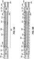
- the sleeve 502 can have one or more stretch resistant fibers 800 positioned within a wall of the sleeve 502.
- the stretch resistant fibers 800 can include polymeric fibers and/or metallic fibers.
- the stretch resistant fibers 800 can be oriented within the wall of the sleeve 502 in a linear orientation, as shown in FIG. 7A , or in one or more helical orientations, as shown in FIG. 7B .
- the stretch resistant fibers 800 can be incorporated into the wall of the sleeve 502 during the extrusion process of the fibered sleeve 502.
- the fibered sleeve 502 can have a wall thickness T measuring within a range including about 0.025 mm (0.001 inch) to about 0.076 mm (0.003 inch).
- the fibered sleeve 502 can further be coated with a hydrophilic coating to further minimize friction during intravascular navigation.
- FIG. 7C is an illustration of a cross section of a delivery member 10 according to aspects of the present invention.
- the fibered sleeve 502 can be fused or glued to the flexible tubular section 200, the proximal hypotube 100, and/or the distal hypotube 300, such that the fibered sleeve 502 prevents the flexible tubular section 200 from stretching while the delivery member 10 is manipulated in the vasculature, while also preserving the flexibility of the distal hypotube 300.
- the fibered sleeve 502 can also be fused through openings of the flexible tubular section 200.
- the terms “about” or “approximately” for any numerical values or ranges indicate a suitable dimensional tolerance that allows the part or collection of components to function for its intended purpose as described herein. More specifically, “about” or “approximately” may refer to the range of values ⁇ 20% of the recited value, e.g. "about 90%” may refer to the range of values from 71% to 99%.
Landscapes
- Health & Medical Sciences (AREA)
- Surgery (AREA)
- Life Sciences & Earth Sciences (AREA)
- Heart & Thoracic Surgery (AREA)
- Nuclear Medicine, Radiotherapy & Molecular Imaging (AREA)
- Vascular Medicine (AREA)
- Engineering & Computer Science (AREA)
- Biomedical Technology (AREA)
- Reproductive Health (AREA)
- Medical Informatics (AREA)
- Molecular Biology (AREA)
- Animal Behavior & Ethology (AREA)
- General Health & Medical Sciences (AREA)
- Public Health (AREA)
- Veterinary Medicine (AREA)
- Surgical Instruments (AREA)
Claims (11)
- Abgabeelement zum Abgeben einer implantierbaren medizinischen Vorrichtung an eine Zielstelle eines Körpergefäßes, das Abgabeelement umfassend:ein distales Hyporohr (300), umfassend ein distales Ende (304), das geformt ist, um die implantierbare medizinische Vorrichtung aufzunehmen;einen flexiblen rohrförmigen Abschnitt (200), der an einem proximalen Ende (302) des distalen Hyporohrs befestigt ist, der flexible rohrförmige Abschnitt umfassend Öffnungen dahindurch;ein proximales Hyporohr (100), das an einem proximalen Ende (202) des flexiblen rohrförmigen Abschnitts befestigt ist;ein Lumen (208), das sich durch das distale Hyporohr, den flexiblen rohrförmigen Abschnitt und das proximale Hyporohr erstreckt;gekennzeichnet durch:ein dehnungsbeständiges Element (600), das außerhalb des Lumens positioniert ist, an dem proximalen Hyporohr befestigt ist, an dem distalen Hyporohr befestigt ist und sich entlang mindestens eines Anteils einer Außenoberfläche des flexiblen rohrförmigen Abschnitts erstreckt; undeine flexible Hülse (500), die mindestens einen Großteil der Außenoberfläche des flexiblen rohrförmigen Abschnitts und des dehnungsbeständigen Elements bedeckt.
- Abgabeelement nach Anspruch 1, ferner umfassend:
ein Eingriffssystem (140, 400), das beweglich ist, um eine implantierbare medizinische Vorrichtung, die an dem distalen Ende des distalen Hyporohrs in Eingriff steht, in Eingriff zu nehmen und einzusetzen, das Eingriffssystem umfassend:einen Schleifendraht (400), der sich durch eine Öffnung in der implantierbaren medizinischen Vorrichtung erstreckt, wodurch das Eingriffssystem die implantierbare medizinische Vorrichtung in Eingriff nimmt, und der beweglich ist, um aus der Öffnung in der implantierbaren medizinischen Vorrichtung zurückgezogen zu werden, um die implantierbare medizinische Vorrichtung einzusetzen, undeinen Zugdraht (140), der sich durch das Lumen erstreckt, der mit dem Schleifendraht in Eingriff steht und dadurch das Eingriffssystem mit der implantierbaren medizinischen Vorrichtung in Eingriff bringt, und der beweglich ist, um proximal zurückgezogen zu werden, um den Schleifendraht zu lösen, um die implantierbare medizinische Vorrichtung einzusetzen. - Abgabeelement nach Anspruch 2,wobei das distale Hyporohr einen komprimierbaren Anteil (306) umfasst, der von einem komprimierten Zustand in einen verlängerten Zustand beweglich ist, undwobei das Eingriffssystem den komprimierbaren Anteil in dem komprimierten Zustand hält, wenn er mit der implantierbaren medizinischen Vorrichtung in Eingriff steht.
- Abgabeelement nach Anspruch 1, wobei der flexible rohrförmige Abschnitt umfasst:eine nicht röntgendichte proximale Spule (212), die sich von dem proximalen Ende des flexiblen rohrförmigen Abschnitts erstreckt;eine nicht röntgendichte distale Spule (214), die sich von dem distalen Ende des flexiblen rohrförmigen Abschnitts erstreckt; undeine röntgendichte zentrale Spule (216), die sich zwischen der nicht röntgendichten proximalen Spule und der nicht röntgendichten distalen Spule erstreckt.
- Abgabeelement nach Anspruch 1, wobei der flexible rohrförmige Abschnitt umfasst:
einen Draht, der gewickelt ist, um den flexiblen rohrförmigen Abschnitt auszubilden und einen Anteil des Lumens zu definieren, der Draht umfassend einen Durchmesser von etwa 0,02 mm (0,0008 Zoll) bis etwa 0,1 mm (0,005 Zoll). - Abgabeelement nach Anspruch 1,wobei die flexible Hülse ein Polymer umfasst, undwobei die flexible Hülse Additive umfasst, die wirksam sind, um eine Gleitfähigkeit des Polymers zu erhöhen.
- Abgabeelement nach Anspruch 1, wobei die flexible Hülse an dem proximalen Hyporohr und dem distalen Hyporohr befestigt ist.
- Abgabeelement nach Anspruch 1, wobei das Abgabeelement eine Länge umfasst, die von dem proximalen Ende des flexiblen rohrförmigen Abschnitts zu dem distalen Ende des distalen Hyporohrs messbar ist, und wobei die Länge etwa 40 cm misst.
- Verfahren zum Konstruieren eines Abgabeelements zum Abgeben einer implantierbaren medizinischen Vorrichtung, das Verfahren umfassend:Auswählen eines ersten Hyporohrs (300), umfassend ein erstes Lumen dahindurch;Auswählen eines zweiten Hyporohrs (100), umfassend ein zweites Lumen dahindurch;Ausbilden eines flexiblen rohrförmigen Abschnitts (200), der sich von einem distalen Ende (104) des zweiten Hyporohrs zu einem proximalen Ende (302) des ersten Hyporohrs derart erstreckt, dass der flexible rohrförmige Abschnitt ein drittes Lumen dahindurch definiert;Befestigen eines distalen Anteils eines dehnungsbeständigen Elements (600) an dem ersten Hyporohr und Befestigen eines proximalen Anteils des dehnungsbeständigen Elements an dem zweiten Hyporohr,gekennzeichnet wobei ein Zwischenanteil des dehnungsbeständigen Elements außerhalb des ersten, zweiten und dritten Lumens positioniert ist;Auswählen einer flexiblen Hülse (500);Bedecken von mindestens einem Großteil der Außenoberfläche des flexiblen rohrförmigen Abschnitts mit der flexiblen Hülse; undlösbares Befestigen der implantierbaren medizinischen Vorrichtung an dem Abgabeelement in der Nähe eines distalen Endes des ersten Hyporohrs.
- Verfahren nach Anspruch 9, wobei der Schritt des Auswählens der flexiblen Hülse ferner umfasst:
Auswählen der flexiblen Hülse, umfassend ein Polymer, und ferner umfassend mindestens eines von:einem Additiv, das wirksam ist, um die Gleitfähigkeit des Polymers zu erhöhen,einer dehnungsbeständigen Faser, umfassend ein Polymer, undeiner dehnungsbeständigen Faser, umfassend ein Metall. - Verfahren nach Anspruch 9, wobei der Schritt des lösbaren Befestigens der implantierbaren medizinischen Vorrichtung an dem Abgabeelement in der Nähe eines distalen Endes des ersten Hyporohrs ferner umfasst:Komprimieren des ersten Hyporohrs; undlösbares Befestigen der implantierbaren medizinischen Vorrichtung an dem Abgabeelement in der Nähe des distalen Endes des komprimierten ersten Hyporohrs.
Applications Claiming Priority (2)
| Application Number | Priority Date | Filing Date | Title |
|---|---|---|---|
| US17/218,801 US12496431B2 (en) | 2019-07-03 | 2021-03-31 | Medical device delivery member with flexible stretch resistant distal portion |
| US17/379,276 US20210346002A1 (en) | 2019-07-03 | 2021-07-19 | Medical device delivery member with flexible stretch resistant distal portion |
Publications (3)
| Publication Number | Publication Date |
|---|---|
| EP4066752A1 EP4066752A1 (de) | 2022-10-05 |
| EP4066752C0 EP4066752C0 (de) | 2025-04-30 |
| EP4066752B1 true EP4066752B1 (de) | 2025-04-30 |
Family
ID=80999561
Family Applications (1)
| Application Number | Title | Priority Date | Filing Date |
|---|---|---|---|
| EP22165292.8A Active EP4066752B1 (de) | 2021-03-31 | 2022-03-30 | Abgabeelement einer medizinischen vorrichtung mit flexiblem, dehnbeständigem distalem abschnitt |
Country Status (1)
| Country | Link |
|---|---|
| EP (1) | EP4066752B1 (de) |
Families Citing this family (1)
| Publication number | Priority date | Publication date | Assignee | Title |
|---|---|---|---|---|
| CN119112276B (zh) * | 2024-09-13 | 2025-09-30 | 聚辉医疗科技(深圳)有限公司 | 植入医疗器械 |
Family Cites Families (4)
| Publication number | Priority date | Publication date | Assignee | Title |
|---|---|---|---|---|
| US6723108B1 (en) * | 2000-09-18 | 2004-04-20 | Cordis Neurovascular, Inc | Foam matrix embolization device |
| US10806462B2 (en) | 2017-12-21 | 2020-10-20 | DePuy Synthes Products, Inc. | Implantable medical device detachment system with split tube and cylindrical coupling |
| US10806461B2 (en) | 2018-04-27 | 2020-10-20 | DePuy Synthes Products, Inc. | Implantable medical device detachment system with split tube |
| US11207494B2 (en) * | 2019-07-03 | 2021-12-28 | DePuy Synthes Products, Inc. | Medical device delivery member with flexible stretch resistant distal portion |
-
2022
- 2022-03-30 EP EP22165292.8A patent/EP4066752B1/de active Active
Also Published As
| Publication number | Publication date |
|---|---|
| EP4066752C0 (de) | 2025-04-30 |
| EP4066752A1 (de) | 2022-10-05 |
Similar Documents
| Publication | Publication Date | Title |
|---|---|---|
| US12496431B2 (en) | Medical device delivery member with flexible stretch resistant distal portion | |
| EP3799803B1 (de) | Abgabeelement einer medizinischen vorrichtung mit flexibler dehnungsbeständiger mechanischer freigabe | |
| US20210346002A1 (en) | Medical device delivery member with flexible stretch resistant distal portion | |
| US11457922B2 (en) | Medical device delivery member with flexible stretch resistant distal portion | |
| US11951026B2 (en) | Implantable medical device detachment system with flexible braid section | |
| EP4066752B1 (de) | Abgabeelement einer medizinischen vorrichtung mit flexiblem, dehnbeständigem distalem abschnitt | |
| WO2023199147A1 (en) | Medical device delivery member with positioning window | |
| ES3033856T3 (en) | Medical device delivery member with flexible stretch resistant distal portion | |
| US20220240977A1 (en) | Medical device delivery member with positioning window |
Legal Events
| Date | Code | Title | Description |
|---|---|---|---|
| PUAI | Public reference made under article 153(3) epc to a published international application that has entered the european phase |
Free format text: ORIGINAL CODE: 0009012 |
|
| STAA | Information on the status of an ep patent application or granted ep patent |
Free format text: STATUS: THE APPLICATION HAS BEEN PUBLISHED |
|
| AK | Designated contracting states |
Kind code of ref document: A1 Designated state(s): AL AT BE BG CH CY CZ DE DK EE ES FI FR GB GR HR HU IE IS IT LI LT LU LV MC MK MT NL NO PL PT RO RS SE SI SK SM TR |
|
| STAA | Information on the status of an ep patent application or granted ep patent |
Free format text: STATUS: REQUEST FOR EXAMINATION WAS MADE |
|
| 17P | Request for examination filed |
Effective date: 20230303 |
|
| RBV | Designated contracting states (corrected) |
Designated state(s): AL AT BE BG CH CY CZ DE DK EE ES FI FR GB GR HR HU IE IS IT LI LT LU LV MC MK MT NL NO PL PT RO RS SE SI SK SM TR |
|
| GRAP | Despatch of communication of intention to grant a patent |
Free format text: ORIGINAL CODE: EPIDOSNIGR1 |
|
| STAA | Information on the status of an ep patent application or granted ep patent |
Free format text: STATUS: GRANT OF PATENT IS INTENDED |
|
| INTG | Intention to grant announced |
Effective date: 20241211 |
|
| GRAS | Grant fee paid |
Free format text: ORIGINAL CODE: EPIDOSNIGR3 |
|
| GRAA | (expected) grant |
Free format text: ORIGINAL CODE: 0009210 |
|
| STAA | Information on the status of an ep patent application or granted ep patent |
Free format text: STATUS: THE PATENT HAS BEEN GRANTED |
|
| AK | Designated contracting states |
Kind code of ref document: B1 Designated state(s): AL AT BE BG CH CY CZ DE DK EE ES FI FR GB GR HR HU IE IS IT LI LT LU LV MC MK MT NL NO PL PT RO RS SE SI SK SM TR |
|
| REG | Reference to a national code |
Ref country code: CH Ref legal event code: EP Ref country code: GB Ref legal event code: FG4D |
|
| REG | Reference to a national code |
Ref country code: DE Ref legal event code: R096 Ref document number: 602022013760 Country of ref document: DE |
|
| REG | Reference to a national code |
Ref country code: IE Ref legal event code: FG4D |
|
| U01 | Request for unitary effect filed |
Effective date: 20250520 |
|
| U07 | Unitary effect registered |
Designated state(s): AT BE BG DE DK EE FI FR IT LT LU LV MT NL PT RO SE SI Effective date: 20250528 |
|
| REG | Reference to a national code |
Ref country code: ES Ref legal event code: FG2A Ref document number: 3033856 Country of ref document: ES Kind code of ref document: T3 Effective date: 20250808 |
|
| PG25 | Lapsed in a contracting state [announced via postgrant information from national office to epo] |
Ref country code: NO Free format text: LAPSE BECAUSE OF FAILURE TO SUBMIT A TRANSLATION OF THE DESCRIPTION OR TO PAY THE FEE WITHIN THE PRESCRIBED TIME-LIMIT Effective date: 20250730 Ref country code: GR Free format text: LAPSE BECAUSE OF FAILURE TO SUBMIT A TRANSLATION OF THE DESCRIPTION OR TO PAY THE FEE WITHIN THE PRESCRIBED TIME-LIMIT Effective date: 20250731 |
|
| PG25 | Lapsed in a contracting state [announced via postgrant information from national office to epo] |
Ref country code: PL Free format text: LAPSE BECAUSE OF FAILURE TO SUBMIT A TRANSLATION OF THE DESCRIPTION OR TO PAY THE FEE WITHIN THE PRESCRIBED TIME-LIMIT Effective date: 20250430 |
|
| PG25 | Lapsed in a contracting state [announced via postgrant information from national office to epo] |
Ref country code: HR Free format text: LAPSE BECAUSE OF FAILURE TO SUBMIT A TRANSLATION OF THE DESCRIPTION OR TO PAY THE FEE WITHIN THE PRESCRIBED TIME-LIMIT Effective date: 20250430 |
|
| PG25 | Lapsed in a contracting state [announced via postgrant information from national office to epo] |
Ref country code: RS Free format text: LAPSE BECAUSE OF FAILURE TO SUBMIT A TRANSLATION OF THE DESCRIPTION OR TO PAY THE FEE WITHIN THE PRESCRIBED TIME-LIMIT Effective date: 20250731 |
|
| PG25 | Lapsed in a contracting state [announced via postgrant information from national office to epo] |
Ref country code: IS Free format text: LAPSE BECAUSE OF FAILURE TO SUBMIT A TRANSLATION OF THE DESCRIPTION OR TO PAY THE FEE WITHIN THE PRESCRIBED TIME-LIMIT Effective date: 20250830 |
|
| PG25 | Lapsed in a contracting state [announced via postgrant information from national office to epo] |
Ref country code: SM Free format text: LAPSE BECAUSE OF FAILURE TO SUBMIT A TRANSLATION OF THE DESCRIPTION OR TO PAY THE FEE WITHIN THE PRESCRIBED TIME-LIMIT Effective date: 20250430 |
|
| PG25 | Lapsed in a contracting state [announced via postgrant information from national office to epo] |
Ref country code: CZ Free format text: LAPSE BECAUSE OF FAILURE TO SUBMIT A TRANSLATION OF THE DESCRIPTION OR TO PAY THE FEE WITHIN THE PRESCRIBED TIME-LIMIT Effective date: 20250430 |
|
| PG25 | Lapsed in a contracting state [announced via postgrant information from national office to epo] |
Ref country code: SK Free format text: LAPSE BECAUSE OF FAILURE TO SUBMIT A TRANSLATION OF THE DESCRIPTION OR TO PAY THE FEE WITHIN THE PRESCRIBED TIME-LIMIT Effective date: 20250430 |
|
| PLBE | No opposition filed within time limit |
Free format text: ORIGINAL CODE: 0009261 |
|
| STAA | Information on the status of an ep patent application or granted ep patent |
Free format text: STATUS: NO OPPOSITION FILED WITHIN TIME LIMIT |
|
| REG | Reference to a national code |
Ref country code: CH Ref legal event code: L10 Free format text: ST27 STATUS EVENT CODE: U-0-0-L10-L00 (AS PROVIDED BY THE NATIONAL OFFICE) Effective date: 20260311 |
|
| U20 | Renewal fee for the european patent with unitary effect paid |
Year of fee payment: 5 Effective date: 20260209 |
|
| 26N | No opposition filed |
Effective date: 20260202 |
|
| PGFP | Annual fee paid to national office [announced via postgrant information from national office to epo] |
Ref country code: IE Payment date: 20260211 Year of fee payment: 5 |