EP3797983B1 - Hilfsvorrichtung zum positionieren eines in-cure-labels an einer formfläche einer vulkanisationsform - Google Patents
Hilfsvorrichtung zum positionieren eines in-cure-labels an einer formfläche einer vulkanisationsform Download PDFInfo
- Publication number
- EP3797983B1 EP3797983B1 EP20192888.4A EP20192888A EP3797983B1 EP 3797983 B1 EP3797983 B1 EP 3797983B1 EP 20192888 A EP20192888 A EP 20192888A EP 3797983 B1 EP3797983 B1 EP 3797983B1
- Authority
- EP
- European Patent Office
- Prior art keywords
- cure
- label
- support
- applicator
- grip element
- Prior art date
- Legal status (The legal status is an assumption and is not a legal conclusion. Google has not performed a legal analysis and makes no representation as to the accuracy of the status listed.)
- Active
Links
Images

Classifications
-
- B—PERFORMING OPERATIONS; TRANSPORTING
- B29—WORKING OF PLASTICS; WORKING OF SUBSTANCES IN A PLASTIC STATE IN GENERAL
- B29D—PRODUCING PARTICULAR ARTICLES FROM PLASTICS OR FROM SUBSTANCES IN A PLASTIC STATE
- B29D30/00—Producing pneumatic or solid tyres or parts thereof
- B29D30/06—Pneumatic tyres or parts thereof (e.g. produced by casting, moulding, compression moulding, injection moulding, centrifugal casting)
- B29D30/72—Side-walls
-
- B—PERFORMING OPERATIONS; TRANSPORTING
- B29—WORKING OF PLASTICS; WORKING OF SUBSTANCES IN A PLASTIC STATE IN GENERAL
- B29C—SHAPING OR JOINING OF PLASTICS; SHAPING OF MATERIAL IN A PLASTIC STATE, NOT OTHERWISE PROVIDED FOR; AFTER-TREATMENT OF THE SHAPED PRODUCTS, e.g. REPAIRING
- B29C31/00—Handling, e.g. feeding of the material to be shaped, storage of plastics material before moulding; Automation, i.e. automated handling lines in plastics processing plants, e.g. using manipulators or robots
- B29C31/008—Handling preformed parts, e.g. inserts
-
- B—PERFORMING OPERATIONS; TRANSPORTING
- B29—WORKING OF PLASTICS; WORKING OF SUBSTANCES IN A PLASTIC STATE IN GENERAL
- B29C—SHAPING OR JOINING OF PLASTICS; SHAPING OF MATERIAL IN A PLASTIC STATE, NOT OTHERWISE PROVIDED FOR; AFTER-TREATMENT OF THE SHAPED PRODUCTS, e.g. REPAIRING
- B29C33/00—Moulds or cores; Details thereof or accessories therefor
- B29C33/12—Moulds or cores; Details thereof or accessories therefor with incorporated means for positioning inserts, e.g. labels
-
- B—PERFORMING OPERATIONS; TRANSPORTING
- B29—WORKING OF PLASTICS; WORKING OF SUBSTANCES IN A PLASTIC STATE IN GENERAL
- B29D—PRODUCING PARTICULAR ARTICLES FROM PLASTICS OR FROM SUBSTANCES IN A PLASTIC STATE
- B29D30/00—Producing pneumatic or solid tyres or parts thereof
- B29D30/06—Pneumatic tyres or parts thereof (e.g. produced by casting, moulding, compression moulding, injection moulding, centrifugal casting)
- B29D30/0601—Vulcanising tyres; Vulcanising presses for tyres
- B29D30/0606—Vulcanising moulds not integral with vulcanising presses
-
- B—PERFORMING OPERATIONS; TRANSPORTING
- B29—WORKING OF PLASTICS; WORKING OF SUBSTANCES IN A PLASTIC STATE IN GENERAL
- B29D—PRODUCING PARTICULAR ARTICLES FROM PLASTICS OR FROM SUBSTANCES IN A PLASTIC STATE
- B29D30/00—Producing pneumatic or solid tyres or parts thereof
- B29D30/06—Pneumatic tyres or parts thereof (e.g. produced by casting, moulding, compression moulding, injection moulding, centrifugal casting)
- B29D30/0601—Vulcanising tyres; Vulcanising presses for tyres
- B29D30/0606—Vulcanising moulds not integral with vulcanising presses
- B29D2030/0607—Constructional features of the moulds
-
- B—PERFORMING OPERATIONS; TRANSPORTING
- B29—WORKING OF PLASTICS; WORKING OF SUBSTANCES IN A PLASTIC STATE IN GENERAL
- B29D—PRODUCING PARTICULAR ARTICLES FROM PLASTICS OR FROM SUBSTANCES IN A PLASTIC STATE
- B29D30/00—Producing pneumatic or solid tyres or parts thereof
- B29D30/06—Pneumatic tyres or parts thereof (e.g. produced by casting, moulding, compression moulding, injection moulding, centrifugal casting)
- B29D30/72—Side-walls
- B29D2030/726—Decorating or marking the sidewalls before tyre vulcanization
Definitions
- the invention relates to an auxiliary device for positioning an in-cure label on a mold surface of a vulcanization mold for a pneumatic vehicle tire.
- the documents U.S. 4,017,352 and DE 10 2018 221100 basically shows an auxiliary device for positioning an in-cure label on a mold surface of a blank of a pneumatic vehicle tire to be vulcanized.
- the labels are usually designed as peripheral sections of circular rings and are made of one or more thin, unvulcanized or pre-vulcanized rubber mixture layers, which are printed on one side in color or have been provided with characters using transfer foils or the like. On the other side, their backside, which is connected to the tire sidewall, the labels are covered with a protective film.
- In-cure labels are manually removed from a buffer, the protective film is removed from the back of the in-cure label, and then the in-cure label is placed in the lower sidewall tray of the vulcanization mold, back-side up, using an exact Positioning is carried out by spring-loaded pins fixed in the side wall shell, which engage in corresponding openings in the in-cure label.
- the positioning of the in-cure label in the usually still hot vulcanization mold requires precise handling by the operator, in particular to prevent any contamination of the in-cure label and injury to the operator from the hot vulcanization mold. In order to minimize the risk of contamination of the in-cure label and at the same time increase safety for the operator, the operator must wear gloves, which also makes handling the in-cure label more difficult.
- the object of the invention is to provide an auxiliary device by means of which the operator can position the in-cure label in the vulcanization mold safely, cleanly, quickly and precisely.
- the auxiliary device is an applicator with a grip element and a support for the in-cure label running at an obtuse angle thereto, with holding elements being attached to the side of the grip element running at the obtuse angle to the support are such that the in-cure label can be clamped between the holding elements and the support in a detachable manner
- the invention therefore provides an applicator with which in-cure labels can be positioned by an operator in a clean, quick and precise manner on the pins on the mold surface of the vulcanization mold. It is of particular advantage that the in-cure label is positioned flat and in a stable position in the applicator beforehand. The angling of the handle from the cradle allows the in-cure label to be placed on the tire mold without risk of the operator coming into contact with the hot mold surface. Touching the in-cure label is limited to placing it in the applicator, after positioning the in-cure label on the mold surface, the pins hold the in-cure label and it is only a matter of moving away and thus pulling off the applicator required by the In-Cure label.
- the overlay is designed in accordance with a strip-shaped edge section of the in-cure label. This measure ensures optimal positioning of the in-cure label in the applicator, since the contact surface is adapted to the shape of the in-cure label.
- the obtuse angle between the grip element and the support is preferably 160° to 175°, in particular of the order of 170°. This measure ensures comfortable handling of the applicator for positioning the in-cure label on the mold surface of the vulcanization mold and when detaching the applicator from the in-cure label after the in-cure label has been positioned.
- At least the support, and preferably also the grip element has a longitudinal extent which is adapted to the longitudinal extent of the in-cure label.
- the applicator therefore picks up the in-cure label in such a way that it can be precisely positioned on the pins on the mold surface of the vulcanization mold.
- a correspondingly large or elongated grip element allows for particularly comfortable handling of the applicator.
- two sliding elements are arranged on the side of the grip element running at the obtuse angle to the support, which protrude beyond the grip element above the support and overlap with the lateral edges of the support and are each provided with a roller element at their ends are, which is provided with at least one freely rotatable castor, the axis of rotation of which is oriented in the longitudinal extension of the support.
- the sliding rollers support easy removal of the applicator from the in-cure label positioned on the mold surface of the vulcanization mold.
- each roller element has two slide rollers, whereby to pull off the applicator after positioning the in-cure label in the vulcanization mold by tilting the applicator, one slide roller with the in-cure label and the other slide roller with the mold surface in Contact can be brought.
- In-cure labels usually have the shape of peripheral sections of circular rings and a width in the order of a few centimeters and are correspondingly adapted to the circular ring shape of the tire sidewall to which they are applied. In-cure labels make it possible to apply a different colored sign, in particular lettering, to tire sidewalls in a durable manner compared to the black rubber material of the sidewall.
- FIG. 3 shows an example of an in-cure label 1, which is printed with the lettering "Continental". 4 shows the in-cure label 1 held on an applicator 2, the non-printed side of the in-cure label 1 being visible.
- the in-cure label 1 has a hole 1a in each of its end regions, which allows the in-cure label 1 to be positioned on spring-loaded pins on the vulcanization mold.
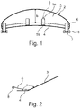
- the applicator 2 ( 1 and 2 ) is an auxiliary device for clean, quick and precise positioning of the in-cure label 2 in the lower side wall shell of a usually still hot vulcanization mold and reduces the risk of contamination of the in-cure label 1 by the operator.
- the applicator 2 has, in the example, an elongated and plate-shaped grip element 3 and a support 4, these two parts running at an angle to one another.
- the handle element 3 protrudes at an obtuse angle ⁇ ( 2 ) of in particular 160° to 175°, in particular in the order of 170°, from the support 4 and, in the embodiment shown, has an outer edge running in an arc.
- the top of the applicator 2 is the side on which the angle ⁇ is present.
- the handle element 3 is made in one piece with the support 4 and consists in particular of metal or a heat-resistant plastic.
- the support 4 is a strip-shaped, designed as a peripheral section of a circular ring Element with a width of for example 12.0 mm to 17.0 mm, in particular of the order of 15.0 mm.
- the support 4 is adapted to the curved shape of the in-cure label 1 in such a way that the edge located between the grip element 3 and the support 4 runs along an arc of a circle with a radius which corresponds to the radius of the arc of a circle at the in 3 and 4 corresponds to the upper edge of the in-cure label 1.
- the width or shape of the support 4 is such that the holes 1a of the in-cure label 1 are exposed when the in-cure label 1 is positioned on the applicator 2 .
- the arc length at the edge of the support 4 to the grip element 3 corresponds at least largely to the arc length of the mentioned upper edge of the in-cure label 1.
- the grip element 3 has a maximum width b of a few centimeters, in particular 5.0 cm to 10.0 cm, so that the operator can easily grasp the applicator 2 by hand.
- the grip element 3 also has a longitudinal extent that is adapted to the longitudinal extent of the support 4 .
- two holding elements 5 are attached, each with a fastening portion 5a, for example riveted.
- a holding section 5b protrudes from the fastening section 5a, for example via kinks in the material of the holding elements 5, which runs parallel to the support 4 and is at a distance from it which is adapted to the thickness of the in-cure label 1 in such a way that the in -Cure label 1 can be clamped without damage between the support 4 and the holding elements 5, but after positioning the in-cure label 1 in the vulcanization mold the applicator 2 can be detached from the in-cure label 1 without any problems.
- a sliding element 6 is fastened to the upper side of the grip element 3, for example also riveted.
- the sliding elements 6 protrude beyond the handle element 3 above the support 4 in overlapping with the lateral edges of the support 4 and are each provided at their ends with a roller element 7 which has two freely rotatable small rollers 7 each.
- the axes of rotation of the sliding rollers 7 run transversely to the pull-off direction (arrow P in Fig.1 ) of the applicator 2.
- the protective film on the printed side of the in-cure label 1 is removed and positioned on the applicator 2 by the operator, who is wearing gloves ( 3 ).
- the operator grips the applicator 2 on the grip element 3 and places the in-cure label 1 on the spring-loaded pins in the mold surface of the vulcanization mold by engaging the pins in the lateral holes 1a formed in the in-cure label 1 .
- the applicator 2 is tilted slightly so that the rollers 7 on the in-cure label 1 and the mold surface pull the applicator 2 off the in-cure label 1.
Landscapes
- Engineering & Computer Science (AREA)
- Mechanical Engineering (AREA)
- Robotics (AREA)
- Heating, Cooling, Or Curing Plastics Or The Like In General (AREA)
- Moulds For Moulding Plastics Or The Like (AREA)
Description
- Die Erfindung betrifft eine Hilfsvorrichtung zum Positionieren eines In-Cure-Labels an einer Formfläche einer Vulkanisationsform für einen Fahrzeugluftreifen. Die Dokumente
US 4 017 352 undDE 10 2018 221100 zeigt grundsätzlich eine Hilfsvorrichtung zum Positionieren eines In-Cure-Label an einer Formfläche eines zu vulkanisierenden Rohlings eines Fahrzeugluftreifens. - Es ist bekannt auf den Seitenwänden von Fahrzeugluftreifen farbige, also nicht schwarze, Zeichen bzw. Beschriftungen anzubringen über farbig gestaltete Labels aufzubringen. Die Labels sind meist als Umfangsabschnitte von Kreisringen gestaltet und Plättchen aus einer oder mehreren dünnen, unvulkanisierten oder vorvulkanisierten Kautschukmischungsschichten, die auf der einen Seite entsprechend farbig bedruckt sind oder per Transferfolien oder dgl. mit Zeichen versehen worden sind. Auf der anderen Seite, ihrer Rückseite, die mit der Reifenseitenwand verbunden wird, sind die Labels mit einer Schutzfolie versehen. In-Cure-Labels werden von Hand einem Puffer entnommen, die Schutzfolie wird von der Rückseite der In-Cure-Labels entfernt und anschließend wird das In-Cure-Label in die untere Seitenwandschale der Vulkanisationsform mit der Rückseite nach oben eingelegt, wobei eine exakte Positionierung durch in der Seitenwandschale befestigte, federbelastete Stifte erfolgt, die in entsprechende Öffnungen des In-Cure-Labels eingreifen. Die Positionierung der In-Cure-Label in der meist noch heißen Vulkanisationsform erfordert von der Bedienperson ein präzises Handling, insbesondere um eine etwaige Kontamination der In-Cure-Label und eine Verletzung der Bedienperson durch die heiße Vulkanisationsform zu verhindern. Um das Kontaminationsrisiko der In-Cure-Label zu minimieren und gleichzeitig die Sicherheit für die Bedienperson zu erhöhen, muss diese Handschuhe tragen, wodurch zusätzlich das Handling der In-Cure-Label erschwert wird.
- Der Erfindung liegt die Aufgabe zugrunde, eine Hilfsvorrichtung zur Verfügung zu stellen mittels welcher für die Bedienperson eine sichere, saubere, schnelle und präzise Positionierung der In-Cure-Label in der Vulkanisationsform möglich ist.
- Gelöst wird die gestellte Aufgabe erfindungsgemäß dadurch, dass die Hilfsvorrichtung ein Applikator mit einem Griffelement und einer zu diesem unter einem stumpfen Winkel verlaufenden Auflage für das In-Cure-Label ist, wobei an der unter dem stumpfen Winkel zur Auflage verlaufenden Seite des Griffelementes Halteelemente befestigt sind, derart, dass das In-Cure-Label zwischen den Halteelementen und der Auflage auflösbare Weise einklemmbar ist
- Die Erfindung stellt daher einen Applikator zur Verfügung, mit welchem In-Cure-Label von einer Bedienperson auf eine saubere, schnelle und präzise Weise auf den Stiften an der Formfläche Vulkanisationsform positioniert werden können. Dabei ist von besonderem Vorteil, dass die In-Cure-Label vorab schon flächig und in einer stabilen Lage im Applikator positioniert wird. Die Abwinkelung des Griffes von der Auflage gestattet es, die In-Cure-Label auf die Reifenheizform aufzusetzen ohne dass die Bedienperson Gefahr läuft, mit der heißen Formfläche in Kontakt zu kommen. Eine Berührung der In-Cure-Label beschränkt sich auf das Einlegen derselben in den Applikator, nach dem Positionieren des In-Cure-Labels auf der Formfläche halten die Stifte das In-Cure-Label und es ist lediglich ein Wegbewegen und damit Abziehen des Applikators vom In-Cure-Label erforderlich.
- Bei einer bevorzugten Ausführung ist die Auflage gemäß einem streifenförmigen Randabschnitt des In-Cure-Label gestaltet. Diese Maßnahme gewährleistet ein optimales Positionieren des In-Cure-Labels im Applikator, da die Auflagefläche an die Gestalt des In-Cure-Labels angepasst ist.
- Bevorzugt beträgt der stumpfe Winkel zwischen dem Griffelement und der Auflage 160° bis 175°, insbesondere in der Größenordnung von 170°. Durch diese Maßnahme wird eine komfortable Handhabung des Applikators zum Positionieren dersIn-Cure-Labels an der Formfläche der Vulkanisationsform und beim Ablösen des Applikators vom In-Cure-Label nach dem Positionieren des In-Cure-Labels gewährleistet.
- Gemäß einer weiteren vorteilhaften Ausgestaltung weist zumindest die Auflage, vorzugsweise weist auch das Griffelement, eine Längserstreckung auf, die an die Längserstreckung des In-Cure-Labels angepasst ist. Der Applikator nimmt daher das In-Cure-Label derart auf, dass es präzise auf den Stiften an der Formfläche der Vulkanisationsform positioniert werden kann. Ein entsprechend großes bzw. langgestrecktes Griffelement gestattet eine besonders komfortable Handhabung des Applikators.
- Bevorzugt ist weiters eine Ausführung, bei der an der unter dem stumpfen Winkel zur Auflage verlaufenden Seite des Griffelementes zwei Gleitelemente angeordnet sind, welche das Griffelement oberhalb der Auflage und in Überlappung mit den seitlichen Rändern der Auflage überragen und an ihren Enden mit je einem Rollenelement versehen sind, welches mit zumindest einer frei drehbaren Gleitrolle versehen ist, deren Drehachse in der Längserstreckung der Auflage orientiert ist. Die Gleitrollen unterstützen ein komfortables Abziehen des Applikators von dem an der Formfläche der Vulkanisationsform positionierten In-Cure-Label.
- Bei einer bevorzugten Ausführungsvariante ist dabei vorgesehen, dass die Gleitrolle zum Abziehen des Applikators nach dem Positionieren des In-Cure-Labels in der Vulkanisationsform durch Kippen des Applikators zugleich mit dem In-Cure-Label und der Formfläche in Kontakt bringbar ist. Bei einer alternativen Ausführung weist jedes Rollenelement zwei Gleitrollen auf, wobei zum Abziehen des Applikators nach dem Positionieren das In-Cure-Label in der Vulkanisationsform durch Kippen des Applikators die eine Gleitrolle mit dem In-Cure-Label und die andere Gleitrolle mit der Formfläche in Kontakt bringbar ist.
- Weitere Merkmale, Vorteile und Einzelheiten der Erfindung werden nun anhand der schematischen Zeichnung, die ein Ausführungsbeispiel darstellt, näher beschrieben. Dabei zeigen
-
Fig. 1 eine Draufsicht auf eine Ausführung eines Applikators, -
Fig. 2 den Applikator in leicht vergrößerter Seitenansicht, -
Fig. 3 eine Draufsicht auf ein Beispiel eines In-Cure-Labels und -
Fig. 4 eine Draufsicht auf den Applikator mit positioniertem In-Cure-Label. - In-Cure-Label weisen üblicherweise die Gestalt von Umfangsabschnitten von Kreisringen sowie eine Breite in der Größenordnung von einigen Zentimetern auf und sind dabei entsprechend an die Kreisringform der Reifenseitenwand, auf welche sie aufgebracht werden, angepasst. In-Cure-Label gestatten es, auf dauerhaltbare Weise eine gegenüber dem schwarzen Gummimaterial der Seitenwand andersfarbige Zeichen, insbesondere Schriftzüge, auf Reifenseitenwänden anzubringen.
-
Fig. 3 zeigt ein Bespiel eines In-Cure-Labels 1, welches mit dem Schriftzug "Continental" bedruckt ist.Fig. 4 zeigt das an einem Applikator 2 gehaltene In-Cure-Label 1, wobei die nicht bedruckte Seite des In-Cure-Labels 1 zu sehen ist. Das In-Cure-Label 1 weist an seinen Endbereichen je ein Loch 1a auf, welches ein Positionieren des In-Cure-Labels 1 auf federbelasteten Stiften an der Vulkanisationsform gestatten. - Der Applikator 2 (
Fig. 1 und Fig. 2 ) ist eine Hilfsvorrichtung zum sauberen, schnellen und präzisen Positionieren der In-Cure-Labels 2 in der unteren Seitenwandschale einer meist noch heißen Vulkanisationsform und reduziert das Kontaminationsrisiko der In-Cure-Label 1 durch die Bedienperson. Der Applikator 2 weist ein im Beispiel langgestrecktes und plattenförmiges Griffelement 3 und eine Auflage 4 auf, wobei diese beiden Teile zueinander gewinkelt verlaufen. Das Griffelement 3 ragt unter einem stumpfen Winkel α (Fig. 2 ) von insbesondere 160° bis 175°, insbesondere in der Größenordnung von 170° von der Auflage 4 ab und weist bei der gezeigten Ausführung eine bogenförmig verlaufende Außenkante auf. Die Oberseite des Applikators 2 ist jene Seite, an welcher der Winkel α vorliegt. Bei der bevorzugten Ausführung ist das Griffelement 3 mit der Auflage 4 einteilig hergestellt und besteht insbesondere aus Metall oder einem hitzebeständigen Kunststoff. Die Auflage 4 ist ein streifenförmiges, als Umfangsabschnitt eines Kreisringes gestaltetes Element mit einer Breite von beispielsweise 12,0 mm bis 17,0 mm, insbesondere in der Größenordnung von 15,0 mm. Die Auflage 4 ist an die gebogene Form des In-Cure-Labels 1 derart angepasst, dass die zwischen dem Griffelement 3 und der Auflage 4 befindliche Kante entlang eines Kreisbogens mit einem Radius verläuft, welcher dem Radius des Kreisbogens an der inFig. 3 und Fig. 4 oberen Kante des In-Cure-Labels 1 entspricht. Die Breite bzw. Gestalt der Auflage 4 ist jedenfalls derart, dass die Löcher 1a des In-Cure-Labels 1 bei am Applikator 2 positioniertem In-Cure-Label 1 frei liegen. Die Bogenlänge an der Kante der Auflage 4 zum Griffelement 3 entspricht zumindest weitgehend der Bogenlänge der erwähnten oberen Kante des In-Cure-Labels 1. - Das Griffelement 3 weist eine größte Breite b von einigen Zentimetern, insbesondere 5,0 cm bis 10,0 cm, auf, sodass die Bedienperson den Applikator 2 von Hand aus gut ergreifen kann. Bei der gezeigten Ausführung weist ferner das Griffelement 3 eine Längserstreckung auf, die an die Längserstreckung der Auflage 4 angepasst ist. An der Oberseite des Griffelementes 3 sind zwei Halteelemente 5 mit je einem Befestigungsabschnitt 5a befestigt, beispielsweise angenietet. Vom Befestigungsabschnitt 5a ragt, beispielsweise über Knicke im Material der Halteelemente 5, ein Halteabschnitt 5b ab, welcher parallel zur Auflage 4 verläuft und zu diesem einen Abstand aufweist, welcher an die Dicke des In-Cure-Labels 1 derart angepasst ist, dass das In-Cure-Label 1 ohne Beschädigung zwischen der Auflage 4 und den Halteelementen 5 zwar eingeklemmt werden kann jedoch nach dem Positionieren des In-Cure-Labels 1 in der Vulkanisationsform der Applikator 2 vom In-Cure-Label 1 problemlos gelöst werden kann.
- An den seitlichen Randbereichen des Griffelementes 3 ist an der Oberseite des Griffelementes 3 jeweils ein Gleitelement 6 befestigt, beispielsweise ebenfalls angenietet. Die Gleitelemente 6 überragen das Griffelement 3 oberhalb der Auflage 4 in Überlappung mit den seitlichen Rändern der Auflage 4 und sind an ihren Enden mit je einem Rollenelement 7 versehen, welches jeweils zwei frei drehbare, kleine Gleitrollen 7 aufweist. Die Drehachsen der Gleitrollen 7 verlaufen quer zur Abziehrichtung (Pfeil P in
Fig.1 ) des Applikators 2. - Zum Positionieren eines In-Cure-Labels 1 in der Vulkanisationsform wird die auf der bedruckten Seite des In-Cure-Labels 1 befindliche Schutzfolie abgezogen und von der Bedienperson, die Handschuhe trägt, am Applikator 2 positioniert (
Fig. 3 ). Die Bedienperson erfasst den Applikator 2 am Griffelement 3 und setzt das In-Cure-Label 1 auf die federbelasteten Stifte in der Formfläche der Vulkanisationsform, indem die Stifte in die im In-Cure-Label 1 ausgebildeten seitlichen Löcher 1a eingreifen. Zum Lösen des Applikators 2 vom positionierten In-Cure-Label 1 wird der Applikator 2 leicht gekippt, sodass durch Abrollen der Gleitrollen 7 am In-Cure-Label 1 und der Formfläche ein Abziehen des Applikators 2 vom In-Cure-Label 1 erfolgt. -
- 1
- In-Cure-Label
- 1a
- seitliches Loch
- 2
- Applikator
- 3
- Griffelement
- 4
- Auflage
- 5
- Halteelement
- 5a
- Befestigungsabschnitt
- 5b
- Halteabschnitt
- 6
- Gleitelement
- 6a
- Befestigungsabschnitt
- 6b
- Gleitabschnitt
- 7
- Rollenelement
- 8
- Gleitrolle
- b
- Breite
- α
- Winkel
Claims (7)
- Hilfsvorrichtung zum Positionieren eines In-Cure-Label (1) an einer Formfläche einer Vulkanisationsform für einen Fahrzeugluftreifen,
dadurch gekennzeichnet,
dass sie ein Applikator (2) mit einem Griffelement (3) und einer zu diesem unter einem stumpfen Winkel (a) verlaufenden Auflage (4) für das In-Cure-Label (1) ist, wobei an der unter dem stumpfen Winkel (a) zur Auflage verlaufenden Seite des Griffelementes (3) Halteelemente (5) befestigt sind, derart, dass das In-Cure-Label (1) zwischen den Halteelementen (5) und der Auflage (4) auflösbare Weise einklemmbar ist. - Hilfsvorrichtung nach Anspruch 1, dadurch gekennzeichnet, dass die Auflage (4) gemäß einem streifenförmigen Randabschnitt des In-Cure-Labels (1) gestaltet ist.
- Hilfsvorrichtung nach Anspruch 1 oder 2, dadurch gekennzeichnet, dass der stumpfe Winkel (a) zwischen dem Griffelement (3) und der Auflage (4) 160° bis 175°, insbesondere in der Größenordnung von 170°, beträgt.
- Hilfsvorrichtung nach einem der Ansprüche 1 bis 3, dadurch gekennzeichnet, dass zumindest die Auflage (4), vorzugsweise auch das Griffelement (3), eine Längserstreckung aufweist bzw. aufweisen, die an die Längserstreckung des In-Cure-Labels (1) angepasst ist.
- Hilfsvorrichtung nach einem der Ansprüche 1 bis 4, dadurch gekennzeichnet, dass an der unter dem stumpfen Winkel (a) zur Auflage (4) verlaufenden Seite des Griffelementes (3) zwei Gleitelemente (6) angeordnet sind, welche das Griffelement (3) oberhalb der Auflage (4) und in Überlappung mit den seitlichen Rändern der Auflage (4) überragen und an ihren Enden mit je einem Rollenelement (7) versehen sind, welches mit zumindest einer frei drehbaren Gleitrolle (8) versehen ist, deren Drehachse in der Längserstreckung der Auflage (4) orientiert ist.
- Hilfsvorrichtung nach Anspruch 5, dadurch gekennzeichnet, dass die Gleitrolle (7) zum Abziehen des Applikators (2) nach dem Positionieren des In-Cure-Labels (1) in der Vulkanisationsform durch Kippen des Applikators (2) zugleich mit dem In-Cure-Label (1) und der Formfläche in Kontakt bringbar ist.
- Hilfsvorrichtung nach Anspruch 5, dadurch gekennzeichnet, dass jedes Rollenelement (7) zwei Gleitrollen (8) aufweist, wobei zum Abziehen des Applikators nach dem Positionieren des In-Cure-Labels (1) in der Vulkanisationsform durch Kippen des Applikators die eine Gleitrolle (8) mit dem In-Cure-Label (1) und die andere Gleitrolle (8) mit der Formfläche in Kontakt bringbar ist.
Applications Claiming Priority (1)
| Application Number | Priority Date | Filing Date | Title |
|---|---|---|---|
| DE102019214967.7A DE102019214967A1 (de) | 2019-09-30 | 2019-09-30 | Hilfsvorrichtung zum Positionieren eines In-Cure-Labels an einer Formfläche einer Vulkanisationsform |
Publications (2)
| Publication Number | Publication Date |
|---|---|
| EP3797983A1 EP3797983A1 (de) | 2021-03-31 |
| EP3797983B1 true EP3797983B1 (de) | 2022-06-01 |
Family
ID=72243029
Family Applications (1)
| Application Number | Title | Priority Date | Filing Date |
|---|---|---|---|
| EP20192888.4A Active EP3797983B1 (de) | 2019-09-30 | 2020-08-26 | Hilfsvorrichtung zum positionieren eines in-cure-labels an einer formfläche einer vulkanisationsform |
Country Status (2)
| Country | Link |
|---|---|
| EP (1) | EP3797983B1 (de) |
| DE (1) | DE102019214967A1 (de) |
Family Cites Families (4)
| Publication number | Priority date | Publication date | Assignee | Title |
|---|---|---|---|---|
| US4017352A (en) * | 1976-05-26 | 1977-04-12 | The Goodyear Tire & Rubber Company | Apparatus used in the application of white sidewall to a tire |
| US5932052A (en) * | 1997-02-10 | 1999-08-03 | Brown; Russell S | Process for applying indicia onto an elastomeric component |
| WO2014156744A1 (ja) * | 2013-03-28 | 2014-10-02 | リンテック株式会社 | タイヤ用粘着シート、タイヤ用粘着シートの製造方法、およびタイヤ用粘着シートの使用方法 |
| DE102018221100A1 (de) * | 2018-12-06 | 2020-06-10 | Continental Reifen Deutschland Gmbh | Vorrichtung zum Einlegen von Seitenwandaufklebern in eine Reifen- Vulkanisationsform |
-
2019
- 2019-09-30 DE DE102019214967.7A patent/DE102019214967A1/de not_active Withdrawn
-
2020
- 2020-08-26 EP EP20192888.4A patent/EP3797983B1/de active Active
Also Published As
| Publication number | Publication date |
|---|---|
| EP3797983A1 (de) | 2021-03-31 |
| DE102019214967A1 (de) | 2021-04-01 |
Similar Documents
| Publication | Publication Date | Title |
|---|---|---|
| DE68906000T2 (de) | Greifvorrichtung für Behälter. | |
| EP0413836B1 (de) | Traggriffbefestigung | |
| DE1505007B2 (de) | Gleitschutz- bzw. reifenschutzkette fuer hintereinander angeordnete raeder eines kraftfahrzeuges | |
| DE3435041C2 (de) | ||
| EP3797983B1 (de) | Hilfsvorrichtung zum positionieren eines in-cure-labels an einer formfläche einer vulkanisationsform | |
| DE202015103482U1 (de) | Etikettiervorrichtung für Behälter | |
| DE602004006474T2 (de) | Reifenabdrückvorrichtung für ein Raddemontiergerät | |
| EP3630629B1 (de) | Palette für eine etikettiermaschine mit austauschbarem elastischen oberflächenelement | |
| DE69228328T2 (de) | Schneid-Stanzvorrichtung für eine Druckvorrichtung | |
| DE1915830C3 (de) | Hebelwerkzeug zur Verwendung beim Reifenwechsel an Fahrzeugrädern | |
| DE1548101B2 (de) | Vorrichtung zum Abziehen eines Uhrglases und zum Abziehen mit dieser Vorrichtung bestimmtes Uhrglas | |
| DE102018221100A1 (de) | Vorrichtung zum Einlegen von Seitenwandaufklebern in eine Reifen- Vulkanisationsform | |
| DE102004006392B4 (de) | Rollvorrichtung für ein defektes Rad eines Kraftfahrzeugs | |
| DE959157C (de) | Gleitschutzvorrichtung fuer Fahrzeugraeder | |
| DE102007050528A1 (de) | Werkzeug, Verfahren und Werkzeugset zum Ablösen von Auswucht-Klebegewichten von Fahrzeugfelgen | |
| US20250001802A1 (en) | Wheel mounting guide bar | |
| DE102007018971B4 (de) | Vorrichtung zum automatischen Herstellen von Wulstkernpaketen | |
| DE2331807C3 (de) | Hilfsträger zum Anordnen, Ausrichten und Übertragen von selbstklebenden typographischen oder anderen Figuren in Folienform | |
| DE10001002C1 (de) | Kabelmesser | |
| DE202015008522U1 (de) | Vorrichtung zum Herauslösen von Teilbereichen aus einer Materialbahn | |
| DE2119654C3 (de) | Verfahren und Werkzeug zum Entfernen von Klebeplaketten von Unterlagen | |
| DE2923164C2 (de) | ||
| EP0199918A1 (de) | Verfahren und Vorrichtung zur Wiederverwendung des Materials von Panzerketten | |
| DE701678C (de) | Vorrichtung zum Einbrennen von Einschnitten in die Laufflaeche von Gummireifen | |
| EP0187214A1 (de) | Handmontage-Gerätesatz für Reifendecken |
Legal Events
| Date | Code | Title | Description |
|---|---|---|---|
| PUAI | Public reference made under article 153(3) epc to a published international application that has entered the european phase |
Free format text: ORIGINAL CODE: 0009012 |
|
| STAA | Information on the status of an ep patent application or granted ep patent |
Free format text: STATUS: THE APPLICATION HAS BEEN PUBLISHED |
|
| AK | Designated contracting states |
Kind code of ref document: A1 Designated state(s): AL AT BE BG CH CY CZ DE DK EE ES FI FR GB GR HR HU IE IS IT LI LT LU LV MC MK MT NL NO PL PT RO RS SE SI SK SM TR |
|
| AX | Request for extension of the european patent |
Extension state: BA ME |
|
| STAA | Information on the status of an ep patent application or granted ep patent |
Free format text: STATUS: REQUEST FOR EXAMINATION WAS MADE |
|
| 17P | Request for examination filed |
Effective date: 20210930 |
|
| RBV | Designated contracting states (corrected) |
Designated state(s): AL AT BE BG CH CY CZ DE DK EE ES FI FR GB GR HR HU IE IS IT LI LT LU LV MC MK MT NL NO PL PT RO RS SE SI SK SM TR |
|
| GRAP | Despatch of communication of intention to grant a patent |
Free format text: ORIGINAL CODE: EPIDOSNIGR1 |
|
| STAA | Information on the status of an ep patent application or granted ep patent |
Free format text: STATUS: GRANT OF PATENT IS INTENDED |
|
| INTG | Intention to grant announced |
Effective date: 20220124 |
|
| GRAS | Grant fee paid |
Free format text: ORIGINAL CODE: EPIDOSNIGR3 |
|
| GRAA | (expected) grant |
Free format text: ORIGINAL CODE: 0009210 |
|
| STAA | Information on the status of an ep patent application or granted ep patent |
Free format text: STATUS: THE PATENT HAS BEEN GRANTED |
|
| AK | Designated contracting states |
Kind code of ref document: B1 Designated state(s): AL AT BE BG CH CY CZ DE DK EE ES FI FR GB GR HR HU IE IS IT LI LT LU LV MC MK MT NL NO PL PT RO RS SE SI SK SM TR |
|
| REG | Reference to a national code |
Ref country code: GB Ref legal event code: FG4D Free format text: NOT ENGLISH |
|
| REG | Reference to a national code |
Ref country code: AT Ref legal event code: REF Ref document number: 1495101 Country of ref document: AT Kind code of ref document: T Effective date: 20220615 Ref country code: CH Ref legal event code: EP Ref country code: DE Ref legal event code: R096 Ref document number: 502020001163 Country of ref document: DE |
|
| REG | Reference to a national code |
Ref country code: IE Ref legal event code: FG4D Free format text: LANGUAGE OF EP DOCUMENT: GERMAN |
|
| REG | Reference to a national code |
Ref country code: LT Ref legal event code: MG9D |
|
| REG | Reference to a national code |
Ref country code: NL Ref legal event code: MP Effective date: 20220601 |
|
| PG25 | Lapsed in a contracting state [announced via postgrant information from national office to epo] |
Ref country code: SE Free format text: LAPSE BECAUSE OF FAILURE TO SUBMIT A TRANSLATION OF THE DESCRIPTION OR TO PAY THE FEE WITHIN THE PRESCRIBED TIME-LIMIT Effective date: 20220601 Ref country code: NO Free format text: LAPSE BECAUSE OF FAILURE TO SUBMIT A TRANSLATION OF THE DESCRIPTION OR TO PAY THE FEE WITHIN THE PRESCRIBED TIME-LIMIT Effective date: 20220901 Ref country code: LT Free format text: LAPSE BECAUSE OF FAILURE TO SUBMIT A TRANSLATION OF THE DESCRIPTION OR TO PAY THE FEE WITHIN THE PRESCRIBED TIME-LIMIT Effective date: 20220601 Ref country code: HR Free format text: LAPSE BECAUSE OF FAILURE TO SUBMIT A TRANSLATION OF THE DESCRIPTION OR TO PAY THE FEE WITHIN THE PRESCRIBED TIME-LIMIT Effective date: 20220601 Ref country code: GR Free format text: LAPSE BECAUSE OF FAILURE TO SUBMIT A TRANSLATION OF THE DESCRIPTION OR TO PAY THE FEE WITHIN THE PRESCRIBED TIME-LIMIT Effective date: 20220902 Ref country code: FI Free format text: LAPSE BECAUSE OF FAILURE TO SUBMIT A TRANSLATION OF THE DESCRIPTION OR TO PAY THE FEE WITHIN THE PRESCRIBED TIME-LIMIT Effective date: 20220601 Ref country code: BG Free format text: LAPSE BECAUSE OF FAILURE TO SUBMIT A TRANSLATION OF THE DESCRIPTION OR TO PAY THE FEE WITHIN THE PRESCRIBED TIME-LIMIT Effective date: 20220901 |
|
| PG25 | Lapsed in a contracting state [announced via postgrant information from national office to epo] |
Ref country code: RS Free format text: LAPSE BECAUSE OF FAILURE TO SUBMIT A TRANSLATION OF THE DESCRIPTION OR TO PAY THE FEE WITHIN THE PRESCRIBED TIME-LIMIT Effective date: 20220601 Ref country code: PL Free format text: LAPSE BECAUSE OF FAILURE TO SUBMIT A TRANSLATION OF THE DESCRIPTION OR TO PAY THE FEE WITHIN THE PRESCRIBED TIME-LIMIT Effective date: 20220601 Ref country code: LV Free format text: LAPSE BECAUSE OF FAILURE TO SUBMIT A TRANSLATION OF THE DESCRIPTION OR TO PAY THE FEE WITHIN THE PRESCRIBED TIME-LIMIT Effective date: 20220601 |
|
| PG25 | Lapsed in a contracting state [announced via postgrant information from national office to epo] |
Ref country code: NL Free format text: LAPSE BECAUSE OF FAILURE TO SUBMIT A TRANSLATION OF THE DESCRIPTION OR TO PAY THE FEE WITHIN THE PRESCRIBED TIME-LIMIT Effective date: 20220601 |
|
| PG25 | Lapsed in a contracting state [announced via postgrant information from national office to epo] |
Ref country code: SM Free format text: LAPSE BECAUSE OF FAILURE TO SUBMIT A TRANSLATION OF THE DESCRIPTION OR TO PAY THE FEE WITHIN THE PRESCRIBED TIME-LIMIT Effective date: 20220601 Ref country code: SK Free format text: LAPSE BECAUSE OF FAILURE TO SUBMIT A TRANSLATION OF THE DESCRIPTION OR TO PAY THE FEE WITHIN THE PRESCRIBED TIME-LIMIT Effective date: 20220601 Ref country code: RO Free format text: LAPSE BECAUSE OF FAILURE TO SUBMIT A TRANSLATION OF THE DESCRIPTION OR TO PAY THE FEE WITHIN THE PRESCRIBED TIME-LIMIT Effective date: 20220601 Ref country code: PT Free format text: LAPSE BECAUSE OF FAILURE TO SUBMIT A TRANSLATION OF THE DESCRIPTION OR TO PAY THE FEE WITHIN THE PRESCRIBED TIME-LIMIT Effective date: 20221003 Ref country code: ES Free format text: LAPSE BECAUSE OF FAILURE TO SUBMIT A TRANSLATION OF THE DESCRIPTION OR TO PAY THE FEE WITHIN THE PRESCRIBED TIME-LIMIT Effective date: 20220601 Ref country code: EE Free format text: LAPSE BECAUSE OF FAILURE TO SUBMIT A TRANSLATION OF THE DESCRIPTION OR TO PAY THE FEE WITHIN THE PRESCRIBED TIME-LIMIT Effective date: 20220601 Ref country code: CZ Free format text: LAPSE BECAUSE OF FAILURE TO SUBMIT A TRANSLATION OF THE DESCRIPTION OR TO PAY THE FEE WITHIN THE PRESCRIBED TIME-LIMIT Effective date: 20220601 |
|
| PG25 | Lapsed in a contracting state [announced via postgrant information from national office to epo] |
Ref country code: IS Free format text: LAPSE BECAUSE OF FAILURE TO SUBMIT A TRANSLATION OF THE DESCRIPTION OR TO PAY THE FEE WITHIN THE PRESCRIBED TIME-LIMIT Effective date: 20221001 |
|
| REG | Reference to a national code |
Ref country code: DE Ref legal event code: R097 Ref document number: 502020001163 Country of ref document: DE |
|
| PG25 | Lapsed in a contracting state [announced via postgrant information from national office to epo] |
Ref country code: MC Free format text: LAPSE BECAUSE OF FAILURE TO SUBMIT A TRANSLATION OF THE DESCRIPTION OR TO PAY THE FEE WITHIN THE PRESCRIBED TIME-LIMIT Effective date: 20220601 Ref country code: AL Free format text: LAPSE BECAUSE OF FAILURE TO SUBMIT A TRANSLATION OF THE DESCRIPTION OR TO PAY THE FEE WITHIN THE PRESCRIBED TIME-LIMIT Effective date: 20220601 |
|
| PLBE | No opposition filed within time limit |
Free format text: ORIGINAL CODE: 0009261 |
|
| STAA | Information on the status of an ep patent application or granted ep patent |
Free format text: STATUS: NO OPPOSITION FILED WITHIN TIME LIMIT |
|
| PG25 | Lapsed in a contracting state [announced via postgrant information from national office to epo] |
Ref country code: LU Free format text: LAPSE BECAUSE OF NON-PAYMENT OF DUE FEES Effective date: 20220826 Ref country code: DK Free format text: LAPSE BECAUSE OF FAILURE TO SUBMIT A TRANSLATION OF THE DESCRIPTION OR TO PAY THE FEE WITHIN THE PRESCRIBED TIME-LIMIT Effective date: 20220601 |
|
| REG | Reference to a national code |
Ref country code: BE Ref legal event code: MM Effective date: 20220831 |
|
| 26N | No opposition filed |
Effective date: 20230302 |
|
| PG25 | Lapsed in a contracting state [announced via postgrant information from national office to epo] |
Ref country code: SI Free format text: LAPSE BECAUSE OF FAILURE TO SUBMIT A TRANSLATION OF THE DESCRIPTION OR TO PAY THE FEE WITHIN THE PRESCRIBED TIME-LIMIT Effective date: 20220601 |
|
| P01 | Opt-out of the competence of the unified patent court (upc) registered |
Effective date: 20230602 |
|
| PG25 | Lapsed in a contracting state [announced via postgrant information from national office to epo] |
Ref country code: IE Free format text: LAPSE BECAUSE OF NON-PAYMENT OF DUE FEES Effective date: 20220826 |
|
| PG25 | Lapsed in a contracting state [announced via postgrant information from national office to epo] |
Ref country code: BE Free format text: LAPSE BECAUSE OF NON-PAYMENT OF DUE FEES Effective date: 20220831 |
|
| PG25 | Lapsed in a contracting state [announced via postgrant information from national office to epo] |
Ref country code: IT Free format text: LAPSE BECAUSE OF FAILURE TO SUBMIT A TRANSLATION OF THE DESCRIPTION OR TO PAY THE FEE WITHIN THE PRESCRIBED TIME-LIMIT Effective date: 20220601 |
|
| REG | Reference to a national code |
Ref country code: DE Ref legal event code: R081 Ref document number: 502020001163 Country of ref document: DE Owner name: CONTINENTAL REIFEN DEUTSCHLAND GMBH, DE Free format text: FORMER OWNER: CONTINENTAL REIFEN DEUTSCHLAND GMBH, 30165 HANNOVER, DE |
|
| REG | Reference to a national code |
Ref country code: CH Ref legal event code: PL |
|
| PG25 | Lapsed in a contracting state [announced via postgrant information from national office to epo] |
Ref country code: CY Free format text: LAPSE BECAUSE OF FAILURE TO SUBMIT A TRANSLATION OF THE DESCRIPTION OR TO PAY THE FEE WITHIN THE PRESCRIBED TIME-LIMIT Effective date: 20220601 Ref country code: CH Free format text: LAPSE BECAUSE OF NON-PAYMENT OF DUE FEES Effective date: 20230831 |
|
| PG25 | Lapsed in a contracting state [announced via postgrant information from national office to epo] |
Ref country code: MK Free format text: LAPSE BECAUSE OF FAILURE TO SUBMIT A TRANSLATION OF THE DESCRIPTION OR TO PAY THE FEE WITHIN THE PRESCRIBED TIME-LIMIT Effective date: 20220601 Ref country code: HU Free format text: LAPSE BECAUSE OF FAILURE TO SUBMIT A TRANSLATION OF THE DESCRIPTION OR TO PAY THE FEE WITHIN THE PRESCRIBED TIME-LIMIT; INVALID AB INITIO Effective date: 20200826 |
|
| PG25 | Lapsed in a contracting state [announced via postgrant information from national office to epo] |
Ref country code: TR Free format text: LAPSE BECAUSE OF FAILURE TO SUBMIT A TRANSLATION OF THE DESCRIPTION OR TO PAY THE FEE WITHIN THE PRESCRIBED TIME-LIMIT Effective date: 20220601 |
|
| PG25 | Lapsed in a contracting state [announced via postgrant information from national office to epo] |
Ref country code: MT Free format text: LAPSE BECAUSE OF FAILURE TO SUBMIT A TRANSLATION OF THE DESCRIPTION OR TO PAY THE FEE WITHIN THE PRESCRIBED TIME-LIMIT Effective date: 20220601 |
|
| PG25 | Lapsed in a contracting state [announced via postgrant information from national office to epo] |
Ref country code: BG Free format text: LAPSE BECAUSE OF FAILURE TO SUBMIT A TRANSLATION OF THE DESCRIPTION OR TO PAY THE FEE WITHIN THE PRESCRIBED TIME-LIMIT Effective date: 20220601 |
|
| PG25 | Lapsed in a contracting state [announced via postgrant information from national office to epo] |
Ref country code: BG Free format text: LAPSE BECAUSE OF FAILURE TO SUBMIT A TRANSLATION OF THE DESCRIPTION OR TO PAY THE FEE WITHIN THE PRESCRIBED TIME-LIMIT Effective date: 20220601 |
|
| GBPC | Gb: european patent ceased through non-payment of renewal fee |
Effective date: 20240826 |
|
| PG25 | Lapsed in a contracting state [announced via postgrant information from national office to epo] |
Ref country code: GB Free format text: LAPSE BECAUSE OF NON-PAYMENT OF DUE FEES Effective date: 20240826 |
|
| PGFP | Annual fee paid to national office [announced via postgrant information from national office to epo] |
Ref country code: DE Payment date: 20250831 Year of fee payment: 6 |
|
| PGFP | Annual fee paid to national office [announced via postgrant information from national office to epo] |
Ref country code: AT Payment date: 20251020 Year of fee payment: 5 Ref country code: FR Payment date: 20250828 Year of fee payment: 6 |