EP3795780A1 - Schloss mit einer riegeleinrichtung - Google Patents
Schloss mit einer riegeleinrichtung Download PDFInfo
- Publication number
- EP3795780A1 EP3795780A1 EP20194782.7A EP20194782A EP3795780A1 EP 3795780 A1 EP3795780 A1 EP 3795780A1 EP 20194782 A EP20194782 A EP 20194782A EP 3795780 A1 EP3795780 A1 EP 3795780A1
- Authority
- EP
- European Patent Office
- Prior art keywords
- lock
- locking
- slide
- coupling device
- locking slide
- Prior art date
- Legal status (The legal status is an assumption and is not a legal conclusion. Google has not performed a legal analysis and makes no representation as to the accuracy of the status listed.)
- Granted
Links
- 230000008878 coupling Effects 0.000 claims abstract description 40
- 238000010168 coupling process Methods 0.000 claims abstract description 40
- 238000005859 coupling reaction Methods 0.000 claims abstract description 40
- 230000000903 blocking effect Effects 0.000 claims abstract description 9
- 230000033001 locomotion Effects 0.000 claims description 23
- 238000009434 installation Methods 0.000 claims description 4
- 230000005540 biological transmission Effects 0.000 claims description 2
- 238000010276 construction Methods 0.000 description 2
- 230000001419 dependent effect Effects 0.000 description 1
Images

Classifications
-
- E—FIXED CONSTRUCTIONS
- E05—LOCKS; KEYS; WINDOW OR DOOR FITTINGS; SAFES
- E05B—LOCKS; ACCESSORIES THEREFOR; HANDCUFFS
- E05B59/00—Locks with latches separate from the lock-bolts or with a plurality of latches or lock-bolts
-
- E—FIXED CONSTRUCTIONS
- E05—LOCKS; KEYS; WINDOW OR DOOR FITTINGS; SAFES
- E05B—LOCKS; ACCESSORIES THEREFOR; HANDCUFFS
- E05B13/00—Devices preventing the key or the handle or both from being used
- E05B13/002—Devices preventing the key or the handle or both from being used locking the handle
- E05B13/004—Devices preventing the key or the handle or both from being used locking the handle by locking the spindle, follower, or the like
-
- E—FIXED CONSTRUCTIONS
- E05—LOCKS; KEYS; WINDOW OR DOOR FITTINGS; SAFES
- E05B—LOCKS; ACCESSORIES THEREFOR; HANDCUFFS
- E05B63/00—Locks or fastenings with special structural characteristics
- E05B63/0065—Operating modes; Transformable to different operating modes
-
- E—FIXED CONSTRUCTIONS
- E05—LOCKS; KEYS; WINDOW OR DOOR FITTINGS; SAFES
- E05B—LOCKS; ACCESSORIES THEREFOR; HANDCUFFS
- E05B65/00—Locks or fastenings for special use
- E05B65/10—Locks or fastenings for special use for panic or emergency doors
Definitions
- the invention relates to a lock with a locking device, the locking device being drivable from a locking position into an unlocking position, with a receptacle for a lock cylinder, with at least one nut provided for connection to a handle, with one of a lock bit of the lock cylinder inserted into the receptacle and a bolt slide that can be driven by the nut for controlling the bolt device and with a coupling device connecting the nut to the bolt slide.
- Such a lock is for example from the EP 3 498 942 A1 known.
- This lock has two segments that can be driven by a lock cylinder. A locking device can be controlled with one of the segments, while a locking device is controlled with the other segment. The locking device then blocks the locking device in the locked position. This gives the lock a high level of protection against manipulation.
- a locking system has become known in which a central lock can be actuated via a lock nut and a lock cylinder.
- the lock follower works via a lock chain on a central bolt.
- the lock cylinder has a bolt lock that can be driven by the lock cylinder and with which the lock chain is held in a locking position or in an unlocking position.
- the invention is based on the problem of developing a lock of the type mentioned at the beginning in such a way that the possibility of unlocking can be controlled particularly conveniently via the handle.
- a locking slide can be coupled to the lock cylinder and that the locking slide can be moved from a position releasing the coupling device into a position blocking the coupling device.
- the locking slide engages in the area of the connection between the handle and the locking device. This avoids direct intervention in the locking device.
- the locking slide blocks the intervention of the handle by blocking the nut.
- the coupling device can consist of a support surface on the locking slide side and a driver nose on the socket side. This means that the lock can be closed via the lock cylinder regardless of the position of the locking slide. Since the unlocking option is controlled by means of the handle via the lock cylinder, the lock is particularly convenient to use.
- the control of the coupling device is particularly simple if the locking slide is held in one position by a latching device and is pretensioned in the direction of the other position.
- the locking slide is preferably held by the latching device in the position that blocks the coupling device.
- the biasing of the locking slide into one position is particularly simple when the locking slide is supported on a stationary component of the lock via a locking slide spring.
- the fixed component is preferably a lock case.
- the release of the bolt slide from the latching device is particularly simple if the bolt slide has a control cam which controls the latching device.
- the locking device is released when the bolt slide is driven by normal closing with the lock cylinder.
- the control cam releases the locking device so that the locking slide is moved into the other position releasing the coupling device due to its bias.
- the coupling device is particularly simple in construction if the coupling device has a follower arm arranged on the follower and a driver nose arranged on the locking slide.
- the coupling device is particularly simple in construction when the locking slide protrudes into the range of motion of the nut arm in the position blocking the coupling device.
- the blocking of the coupling device is particularly simple if the locking slide has a locking lug that can be moved into the range of motion of the components of the coupling device.
- the locking nose protrudes into the range of motion of the coupling device and is thus able to block the movement of the bolt slide via the nut.
- the locking lug can also be moved out of the range of motion of the coupling device and thus release the movement of the bolt slide over the nut.
- the lock is structurally particularly simple when the nut arm has a support surface at its free end, when the support surface faces the driver nose and when the locking nose is in the position blocking the coupling device in front of the support surface and in the coupling device releasing position is arranged outside the range of motion of the support surface.
- the control of the movement of the locking slide in one direction of movement is particularly simple according to another advantageous development of the invention if the locking slide is connected to a tilt jack that can be swiveled into the receptacle of the lock cylinder and if the tilt jack is in the swiveled-in position with its free end in the Receipt of the lock cylinder for driving the locking slide protrudes in one direction of movement.
- This design allows the locking slide to be driven until it is held by the latching device.
- the drive of the tilt jack is dependent on the drive direction of the lock bit of the lock cylinder when the tilt jack is biased into the receptacle of the lock cylinder by a tilt jack spring.
- the tilt lifter can be pushed out of the receptacle of the lock cylinder in one drive direction of the lock bit and axially displaced in the other drive direction from the lock bit to drive the locking slide.
- the coupling device When the coupling device is in the blocked position, according to another advantageous development of the invention, damage to the lock can be avoided if the coupling device has a cross-sectional constriction that limits the force transmission from the nut against the force of the locking slide.
- the cross-sectional constriction forms a predetermined breaking point on the nut, so that if you attempt to forcefully unlock the lock, the damage is limited to the nut. The possibility of unlocking the lock via the nut is thus destroyed.
- the lock is particularly compact and functionally reliable if the bolt slide and the locking slide are arranged on parallel spaced planes and at least one component of the lock is arranged at least in sections in the installation space between these planes.
- the installation space between the bolt slide and the locking slide is used for other components, such as the bolt.
- the slides are ideally arranged close to the lock case and thus on opposite sides of the lock and can therefore be guided reliably and independently of one another. The components between the slides are additionally protected by this arrangement.
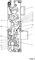
- Figure 1 shows a lock with a bolt device 2 having a bolt 1 and with a latch 3.
- the lock has a receptacle 4 for a lock cylinder 5 and a nut 6 for connection to a handle (not shown).
- the lock cylinder has a lock bit 7 for driving a drive bow 8 guided around the receptacle 4.
- the drive bow 8 is connected via a coupling lever 9 with an in Figure 2
- the locking slide 10 shown is coupled so that the movements of the drive bow 8 are transmitted to the locking slide 10.
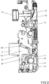
- the bolt slide 10 has a link guide 11 for the bolt 1. When the bolt slide 10 is moved, the bolt 1 is extended or retracted.
- the bolt slide 10 can be connected to further bolt devices, not shown, such as drive rods or secondary locks.
- the socket 6 has a socket arm 12 with a support surface 13 arranged at the free end.
- the support surface 13 faces a driver lug 14 of the bolt slide 10.
- Support surface 13 and driver lug 14 thus form a coupling device 15 for coupling the movement of the nut 6 with the locking device 2.
- the socket 6 also has a latch lever 16 which, when the socket 6 is pivoted, enables the latch 3 to be retracted against the force of a latch spring 17.
- a return spring holds the nut 6 in the basic position shown.
- the lock has a locking slide 19 with a locking lug 20 which is pretensioned by a locking slide spring 18 into the position shown.
- the locking lug 20 is located outside the range of movement of the support surface 13 of the follower arm 12 and thus outside the coupling device 15. The coupling device 15 is thus released and the locking device 2 can be controlled by the follower 6 as described above.
- the locking slide 19 is connected to a pivotable tilt jack 21.
- the tilt lifter 21 is preloaded into the range of motion of the lock bit 7 by means of a schematically illustrated tilt lifter spring 22 and can be pushed out of the range of motion by the drive bow 8.
- the drive bow 8 and thus the locking device 2 are driven and the tilt jack 21 is pressed out of the receptacle 4 for the lock cylinder 5 against the force of the tilt jack spring 22.
- the lock bit 7 of the lock cylinder 5 is driven clockwise, the lock bit 7 comes against the free end of the rocker arm 21 and moves it against the locking slide 19.
- the locking slide 19 is thus moved and the locking lug 20 is moved in front of the support surface 13 of the nut arm 12.
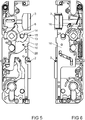
- Figure 3 shows the locking nose 20 moved in front of the support surface 13 of the nut arm 12. This position is reached when starting from the position Figure 1 , the lock bit 7 of the lock cylinder 5 is rotated clockwise. This characterizes the blocked position of the coupling device 15. If one tries, starting from the in Figure 3 To control the locking device 2 by means of the socket 6 shown in the position shown, the support surface 13 of the socket arm 12 is held by the locking lug 20 and thus the coupling device 15 is blocked. A predetermined breaking point formed by a cross-sectional constriction 23 in the nut arm 12 limits the maximum possible force that can be transmitted to the locking nose 20.
- FIG. 3 Furthermore shows Figure 3 that the locking slide 16 is held in the position shown by a latching device 24.
- the latching device 24 and the locking slide 19 have mutually corresponding hooks 25, 26.
- the latching device 24 has a ramp 27 which faces a control cam 28 on the locking slide 10. If the locking slide 10 with the control cam 28 is moved over the ramp 27, the hooks 25, 26 are separated and the movement of the locking slide 19 is released, causing it to return to the in Figure 1 position shown is moved.
- Figure 5 shows the lock Figure 1 when unlocking via the nut 6.
- Figure 6 shows this position in the rear view. Since the locking nose 20 is arranged outside the range of movement of the support surface 13 of the nut arm 12, the support surface 13 moves the driver nose 14 of the bolt slide 10 when the nut 6 is pivoted, so that the bolt device 2 is driven into the unlocked position. In addition, the latch 3 is withdrawn via the latch lever 16.
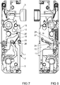
- Figure 7 shows the lock in an unlocked position in which only the latch protrudes.
- Figure 8 shows the lock Figure 7 in a back view. Based on the position Figure 1 the locking device 2 is moved into an unlocked position by means of the lock cylinder 5. The bolt 1 is held in its retracted position in the link guide 11.
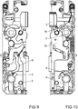
- Figures 9 and 10 show the lock Figure 1 when the latch is withdrawn via the lock cylinder 5.
- the lock cylinder 5 drives the drive bow 8, which moves the bolt slide 10 via the coupling lever 9.
- the bolt slide 10 then drives the latch lever 16 of the nut 6 and pulls the latch 3 back.
Landscapes
- Engineering & Computer Science (AREA)
- Structural Engineering (AREA)
- Business, Economics & Management (AREA)
- Emergency Management (AREA)
- Lock And Its Accessories (AREA)
- Mutual Connection Of Rods And Tubes (AREA)
Abstract
Description
- Die Erfindung betrifft ein Schloss mit einer Riegeleinrichtung, wobei die Riegeleinrichtung von einer Verriegelungsstellung in eine Entriegelungsstellung antreibbar ist, mit einer Aufnahme für einen Schließzylinder, mit zumindest einer zur Verbindung mit einer Handhabe vorgesehenen Nuss, mit einem von einem Schließbart des in die Aufnahme eingesetzten Schließzylinders und von der Nuss antreibbaren Riegelschieber zur Ansteuerung der Riegeleinrichtung und mit einer die Nuss mit dem Riegelschieber verbindenden Koppeleinrichtung.
- Ein solches Schloss ist beispielsweise aus der
EP 3 498 942 A1 bekannt. Dieses Schloss hat zwei über einen Schließzylinder antreibbare Segmente. Mit einem der Segmente lässt sich eine Riegeleinrichtung ansteuern, während mit dem anderen Segment eine Sperreinrichtung angesteuert wird. Die Sperreinrichtung blockiert anschließend die Riegeleinrichtung in der verriegelten Stellung. Damit hat das Schloss einen hohen Schutz vor Manipulation. - Aus der
EP 2 615 229 A2 ist eine Schließanlage bekannt geworden, bei der ein Zentralschloss über eine Schlossnuss und über einen Schließzylinder betätigbar ist. Die Schlossnuss arbeitet über eine Schlosskette auf einem Zentralriegel. Der Schließzylinder hat eine von dem Schließzylinder antreibbare Riegelsperre, mit der die Schlosskette in einer Verriegelungsstellung oder in einer Entriegelungsstellung gehalten wird. - Häufig besteht jedoch der Wunsch, ein Schloss sowohl mittels der Handhabe als auch mittels des Schließzylinders entriegeln zu können. Jedoch soll die Möglichkeit der Entriegelung über die Handhabe abschaltbar sein, so dass zumindest vorübergehend das Schloss ausschließlich mittels des Schließzylinders entriegelt werden kann.
- Der Erfindung liegt das Problem zugrunde, ein Schloss der eingangs genannten Art so weiter zu bilden, dass die Entriegelungsmöglichkeit über die Handhabe besonders komfortabel gesteuert werden kann.
- Dieses Problem wird erfindungsgemäß dadurch gelöst, dass ein Sperrschieber mit dem Schließzylinder koppelbar ist und dass der Sperrschieber von einer die Koppeleinrichtung freigebenden Stellung in eine die Koppeleinrichtung blockierende Stellung bewegbar ist.
- Durch diese Gestaltung greift der Sperrschieber in den Bereich der Verbindung der Handhabe mit der Riegeleinrichtung ein. Ein direkter Eingriff in die Riegeleinrichtung wird hierdurch vermieden. Der Sperrschieber blockiert damit die Eingriffsmöglichkeit der Handhabe durch die Blockierung der Nuss. Die Koppeleinrichtung kann dabei aus einer riegelschieberseitigen Stützfläche und einer nussseitigen Mitnehmernase bestehen. Damit kann das Schloss unabhängig von der Stellung des Sperrschiebers über den Schließzylinder geschlossen werden. Da die Entriegelungsmöglichkeit mittels der Handhabe über den Schließzylinder gesteuert wird, ist das Schloss besonders komfortabel in der Handhabung.
- Die Steuerung der Koppeleinrichtung gestaltet sich gemäß einer anderen vorteilhaften Weiterbildung der Erfindung besonders einfach, wenn der Sperrschieber von einer Rasteinrichtung in einer Stellung gehalten ist und in Richtung der anderen Stellung vorgespannt ist. Vorzugsweise ist der Sperrschieber in der die Koppeleinrichtung blockierende Stellung von der Rasteinrichtung gehalten.
- Die Vorspannung des Sperrschiebers in die eine Stellung gestaltet sich gemäß einer anderen vorteilhaften Weiterbildung der Erfindung besonders einfach, wenn der Sperrschieber über eine Sperrschieberfeder an einem feststehenden Bauteil des Schlosses abgestützt ist. Vorzugsweise ist das feststehende Bauteil ein Schlosskasten.
- Die Lösung des Riegelschiebers von der Rasteinrichtung gestaltet sich gemäß einer anderen vorteilhaften Weiterbildung der Erfindung besonders einfach, wenn der Riegelschieber einen die Rasteinrichtung ansteuernde Steuernocken hat. Durch diese Gestaltung wird die Rasteinrichtung gelöst, wenn der Riegelschieber durch gewöhnliches Schließen mit dem Schließzylinder angetrieben wird. Dabei löst der Steuernocken die Rasteinrichtung, so dass der Sperrschieber durch seine Vorspannung in die andere, die Koppeleinrichtung freigebende Stellung bewegt wird.
- Die Koppeleinrichtung gestaltet sich gemäß einer vorteilhaften Weiterbildung der Erfindung konstruktiv besonders einfach, wenn die Koppeleinrichtung einen an der Nuss angeordneten Nussarm und eine an dem Riegelschieber angeordnete Mitnehmernase hat.
- Die Koppeleinrichtung gestaltet sich gemäß einer vorteilhaften Weiterbildung der Erfindung konstruktiv besonders einfach, wenn der Sperrschieber in der die Koppeleinrichtung blockierende Stellung in den Bewegungsbereich des Nussarms hineinragt.
- Die Blockierung der Koppeleinrichtung gestaltet sich gemäß einer anderen vorteilhaften Weiterbildung der Erfindung besonders einfach, wenn der Sperrschieber eine in den Bewegungsbereich der Bauteile der Koppeleinrichtung hineinbewegbare Sperrnase hat. Durch diese Gestaltung ragt die Sperrnase in den Bewegungsbereich der Koppeleinrichtung hinein und vermag damit die Bewegung des Riegelschiebers über die Nuss zu blockieren. Jedoch kann die Sperrnase auch aus dem Bewegungsbereich der Koppeleinrichtung herausbewegt werden und damit die Bewegung des Riegelschiebers über die Nuss freigeben.
- Das Schloss gestaltet sich gemäß einer anderen vorteilhaften Weiterbildung der Erfindung konstruktiv besonders einfach, wenn der Nussarm an seinem freien Ende eine Stützfläche hat, wenn die Stützfläche der Mitnehmernase gegenübersteht und wenn die Sperrnase in der die Koppeleinrichtung blockierende Stellung vor der Stützfläche und in der die Koppeleinrichtung freigebende Stellung außerhalb des Bewegungsbereichs der Stützfläche angeordnet ist.
- Die Steuerung der Bewegung des Sperrschiebers in die eine Bewegungsrichtung gestaltet sich gemäß einer anderen vorteilhaften Weiterbildung der Erfindung besonders einfach, wenn der Sperrschieber mit einem in die Aufnahme des Schließzylinders einschwenkbaren Kippheber verbunden ist und wenn der Kippheber in der eingeschwenkten Stellung mit seinem freien Ende in die Aufnahme des Schließzylinders zum Antrieb des Sperrschiebers in einer Bewegungsrichtung hineinragt. Durch diese Gestaltung kann der Sperrschieber angetrieben werden, bis er von der Rasteinrichtung gehalten ist.
- Der Antrieb des Kipphebers ist abhängig von der Antriebsrichtung des Schließbartes des Schließzylinders, wenn der Kippheber von einer Kippheberfeder in die Aufnahme des Schließzylinders vorgespannt ist. Durch diese Gestaltung kann der Kippheber in einer Antriebsrichtung des Schließbartes aus der Aufnahme des Schließzylinders herausgedrückt und in der anderen Antriebsrichtung von dem Schließbart zum Antrieb des Sperrschiebers axial verlagert werden.
- Bei in blockierter Stellung befindlicher Koppeleinrichtung lässt sich gemäß einer anderen vorteilhaften Weiterbildung der Erfindung eine Beschädigung des Schlosses vermeiden, wenn die Koppeleinrichtung eine die Kraftübertragung von der Nuss gegen die Kraft des Sperrschiebers begrenzende Querschnittsverengung hat. Durch diese Gestaltung bildet die Querschnittsverengung eine Sollbruchstelle an der Nuss, so dass bei dem Versuch einer gewaltsamen Entriegelung des Schlosses die Beschädigung auf die Nuss begrenzt ist. Die Möglichkeit der Entriegelung des Schlosses über die Nuss ist damit zerstört.
- Das Schloss ist besonders kompakt und funktionssicher aufgebaut, wenn der Riegelschieber und der Sperrschieber auf parallel beabstandeten Ebenen angeordnet sind und in dem Bauraum zwischen diesen Ebenen zumindest ein Bauteil des Schlosses zumindest abschnittsweise angeordnet ist. Dadurch wird der Bauraum zwischen dem Riegelschieber und dem Sperrschieber für weitere Bauteile, etwa dem Riegel, genutzt. Die Schieber sind dabei idealerweise nahe am Schlosskasten und somit auf entgegengesetzten Seiten des Schlosses angeordnet und können dadurch funktionssicher und unabhängig voneinander geführt werden. Die Bauteile zwischen den Schiebern sind durch diese Anordnung zusätzlich geschützt.
- Die Erfindung lässt zahlreiche Ausführungsformen zu. Zur weiteren Verdeutlichung ihres Grundprinzips ist eine davon in der Zeichnung dargestellt und wird nachfolgend beschrieben. Diese zeigt in
- Fig.1
- ein Schloss in einer verriegelten Stellung und freigegebener Stellung einer Koppeleinrichtung,
- Fig.2
- das Schloss aus
Figur 1 in einer Rückansicht, - Fig.3
- das Schloss aus
Figur 1 in verriegelter Stellung und einer blockierten Stellung der Koppeleinrichtung, - Fig.4
- das Schloss aus
Figur 3 in einer Rückansicht, - Fig.5
- das Schloss aus
Figur 1 beim Entriegeln mittels einer Handhabe, - Fig.6
- das Schloss aus
Figur 5 in einer Rückansicht, - Fig.7
- das Schloss aus
Figur 1 beim Entriegeln über einen Schließzylinder, - Fig.8
- das Schloss aus
Figur 7 in einer Rückansicht, - Fig.9
- das Schloss aus
Figur 1 beim Fallenrückzug über den Schließzylinder, - Fig.10
- das Schloss aus
Figur 9 in einer Rückansicht. -
Figur 1 zeigt ein Schloss mit einer einen Riegel 1 aufweisenden Riegeleinrichtung 2 und mit einer Falle 3. Das Schloss hat eine Aufnahme 4 für einen Schließzylinder 5 und eine Nuss 6 zur Verbindung mit einer nicht dargestellten Handhabe. Der Schließzylinder hat einen Schließbart 7 zum Antrieb eines um die Aufnahme 4 geführten Antriebsbogens 8. Der Antriebsbogen 8 ist über einen Koppelhebel 9 mit einem inFigur 2 dargestellten Riegelschieber 10 gekoppelt, so dass die Bewegungen des Antriebsbogens 8 auf den Riegelschieber 10 übertragen werden. WieFigur 2 in einer Rückansicht zeigt, hat der Riegelschieber 10 eine Kulissenführung 11 für den Riegel 1. Bei einer Verschiebung des Riegelschiebers 10 wird der Riegel 1 aus- oder eingefahren. Der Riegelschieber 10 kann mit weiteren, nicht dargestellten Riegeleinrichtungen wie Treibstange oder Nebenschlössern verbunden sein. - Aus
Figur 1 mitFigur 2 ist ersichtlich, dass der Riegelschieber 10 und der Sperrschieber 19 auf parallel beabstandeten Ebenen angeordnet sind und sich in dem Bauraum zwischen diesen Ebenen der Riegel 1 abschnittsweise angeordnet ist. - Die Nuss 6 hat einen Nussarm 12 mit einer am freien Ende angeordneten Stützfläche 13. Die Stützfläche 13 steht einer Mitnehmernase 14 des Riegelschiebers 10 gegenüber. Stützfläche 13 und Mitnehmernase 14 bilden damit eine Koppeleinrichtung 15 zur Koppelung der Bewegung der Nuss 6 mit der Riegeleinrichtung 2. Bei einer Verschwenkung der Nuss 6 wird der Riegelschieber 10 angetrieben und damit der Riegel 1 ebenfalls in die Entriegelungsstellung zurückgezogen. Wie
Figur 2 in einer rückseitigen Ansicht zeigt, hat die Nuss 6 zudem einen Fallenhebel 16, welcher beim Verschwenken der Nuss 6 einen Rückzug der Falle 3 gegen die Kraft einer Fallenfeder 17 ermöglicht. Eine Rückstellfeder hält die Nuss 6 in der dargestellten Grundstellung. - Weiterhin zeigt
Figur 1 , dass das Schloss einen von einer Sperrschieberfeder 18 in die dargestellte Stellung vorgespannten Sperrschieber 19 mit einer Sperrnase 20 hat. In der dargestellten Stellung befindet sich die Sperrnase 20 außerhalb des Bewegungsbereichs der Stützfläche 13 des Nussarms 12 und damit außerhalb der Koppeleinrichtung 15. Damit ist die Koppeleinrichtung 15 freigegeben und die Riegeleinrichtung 2 kann wie oben beschrieben von der Nuss 6 angesteuert werden. - Der Sperrschieber 19 ist mit einem schwenkbaren Kippheber 21 verbunden. Der Kippheber 21 ist mittels einer schematisch dargestellten Kippheberfeder 22 in den Bewegungsbereich des Schließbartes 7 vorgespannt und kann von dem Antriebsbogen 8 aus dem Bewegungsbereich herausgedrückt werden. Beim Antrieb des Schließbartes 7 des Schließzylinders 5 gegen den Uhrzeigersinn aus
Figur 1 werden der Antriebsbogen 8 und damit die Riegeleinrichtung 2 angetrieben und der Kippheber 21 gegen die Kraft der Kippheberfeder 22 aus der Aufnahme 4 für den Schließzylinder 5 herausgedrückt. Beim Antrieb des Schließbartes 7 des Schließzylinders 5 in Uhrzeigersinn gelangt der Schließbart 7 gegen das freie Ende des Kipphebers 21 und verschiebt diesen gegen den Sperrschieber 19. Damit wird der Sperrschieber 19 bewegt und die Sperrnase 20 vor die Stützfläche 13 des Nussarms 12 bewegt. -
Figur 3 zeigt die vor die Stützfläche 13 des Nussarms 12 bewegte Sperrnase 20. Diese Stellung wird erreicht, wenn ausgehend von der Stellung ausFigur 1 , der Schließbart 7 des Schließzylinders 5 im Uhrzeigersinn gedreht wird. Dies kennzeichnet die blockierte Stellung der Koppeleinrichtung 15. Versucht man ausgehend von der inFigur 3 dargestellten Stellung mittels der Nuss 6 die Riegeleinrichtung 2 anzusteuern, wird die Stützfläche 13 des Nussarms 12 von der Sperrnase 20 gehalten und damit die Koppeleinrichtung 15 blockiert. Eine von einer Querschnittsverengung 23 im Nussarm 12 gebildete Sollbruchstelle begrenzt die maximal mögliche Kraft, die auf die Sperrnase 20 übertragen werden kann. - Weiterhin zeigt
Figur 3 , dass der Sperrschieber 16 von einer Rasteinrichtung 24 in der dargestellten Stellung gehalten ist. Die Rasteinrichtung 24 und der Sperrschieber 19 haben einander korrespondierende Haken 25, 26. WieFigur 4 in einer rückseitigen Ansicht des Schlosses ausFigur 3 zeigt, hat die Rasteinrichtung 24 eine Rampe 27, welche einem Steuernocken 28 am Riegelschieber 10 gegenübersteht. Wird der Riegelschieber 10 mit dem Steuernocken 28 über die Rampe 27 bewegt, werden die Haken 25, 26 getrennt und die Bewegung des Sperrschiebers 19 freigegeben, wodurch dieser durch die Kraft der Sperrschieberfeder 18 wieder in die inFigur 1 dargestellte Stellung bewegt wird. -
Figur 5 zeigt das Schloss ausFigur 1 beim Entriegeln über die Nuss 6.Figur 6 zeigt diese Stellung in der rückseitigen Ansicht. Da die Sperrnase 20 außerhalb des Bewegungsbereichs der Stützfläche 13 des Nussarms 12 angeordnet ist, bewegt die Stützfläche 13 beim Verschwenken der Nuss 6 die Mitnehmernase 14 des Riegelschiebers 10, so dass die Riegeleinrichtung 2 in die entriegelte Stellung angetrieben ist. Zudem wird die Falle 3 über den Fallenhebel 16 zurückgezogen. -
Figur 7 zeigt das Schloss in einer entriegelten Stellung, in der ausschließlich die Falle hervorsteht.Figur 8 zeigt das Schloss ausFigur 7 in einer rückseitigen Ansicht. Ausgehend von der Stellung ausFigur 1 ist die Riegeleinrichtung 2 mittels des Schließzylinders 5 in eine entriegelte Stellung bewegt. Der Riegel 1 wird in seiner zurückgezogenen Stellung in der Kulissenführung 11 gehalten. - Vergleicht man die
Figuren 4 und8 zeigt sich, dass beim Entriegeln des Schlosses mittels des Schließzylinders 5 der Steuernocken 28 über die Rampe 27 der Rasteinrichtung 24 bewegt wurde. Bei dieser Bewegung wurden die in denFiguren 3 und7 dargestellten Haken 25, 26 des Sperrschiebers 19 und der Rasteinrichtung 24 getrennt und der Sperrschieber 19 von der Kraft der Sperrschieberfeder 18 in die in denFiguren 3 und 4 dargestellte Stellung bewegt, so dass sich die Sperrnase 20 wieder außerhalb des Bewegungsbereichs der Stützfläche 13 des Nussarms 12 befindet. -
Figuren 9 und 10 zeigen das Schloss ausFigur 1 bei einem Fallenrückzug über den Schließzylinder 5. Der Schließzylinder 5 treibt den Antriebsbogen 8 an, welcher über den Koppelhebel 9 den Riegelschieber 10 verschiebt. Der Riegelschieber 10 treibt anschließend den Fallenhebel 16 der Nuss 6 an und zieht die Falle 3 zurück.
Claims (12)
- Schloss mit einer Riegeleinrichtung (2), wobei die Riegeleinrichtung (2) von einer Verriegelungsstellung in eine Entriegelungsstellung antreibbar ist, mit einer Aufnahme (4) für einen Schließzylinder (5), mit zumindest einer zur Verbindung mit einer Handhabe vorgesehenen Nuss (6), mit einem von einem Schließbart (7) des in die Aufnahme (4) eingesetzten Schließzylinders (5) und von der Nuss (6) antreibbaren Riegelschieber (10) zur Ansteuerung der Riegeleinrichtung (2) und mit einer die Nuss (6) mit dem Riegelschieber (10) verbindenden Koppeleinrichtung (15), dadurch gekennzeichnet, dass ein Sperrschieber (19) mit dem Schließzylinder (5) koppelbar ist und dass der Sperrschieber (19) von einer die Koppeleinrichtung (15) freigebenden Stellung in eine die Koppeleinrichtung (15) blockierende Stellung bewegbar ist.
- Schloss nach Anspruch 1, dadurch gekennzeichnet, dass der Sperrschieber (19) von einer Rasteinrichtung (24) in einer Stellung gehalten ist und in Richtung der anderen Stellung vorgespannt ist.
- Schloss nach Anspruch 1 oder 2, dadurch gekennzeichnet, dass der Sperrschieber (19) über eine Sperrschieberfeder (18) an einem feststehenden Bauteil des Schlosses abgestützt ist.
- Schloss nach Anspruch 2 oder 3, dadurch gekennzeichnet, dass der Riegelschieber (10) einen die Rasteinrichtung (24) ansteuernden Steuernocken (28) hat.
- Schloss nach zumindest einem der vorhergehenden Ansprüche, dadurch gekennzeichnet, dass die Koppeleinrichtung (15) einen an der Nuss (6) angeordneten Nussarm (12) und eine an dem Riegelschieber (10) angeordnete Mitnehmernase (14) hat.
- Schloss nach Anspruch 5, dadurch gekennzeichnet, dass der Sperrschieber (19) in der die Koppeleinrichtung (15) blockierende Stellung in den Bewegungsbereich des Nussarms (12) hineinragt.
- Schloss nach zumindest einem der vorhergehenden Ansprüche, dadurch gekennzeichnet, dass der Sperrschieber (19) eine in den Bewegungsbereich der Bauteile der Koppeleinrichtung (15) hineinbewegbare Sperrnase (20) hat.
- Schloss nach Anspruch 7, dadurch gekennzeichnet, dass der Nussarm (12) an seinem freien Ende eine Stützfläche (13) hat, dass die Stützfläche (13) der Mitnehmernase (14) gegenübersteht und dass die Sperrnase (20) in der die Koppeleinrichtung (15) blockierende Stellung vor der Stützfläche (13) und in der die Koppeleinrichtung (15) freigebende Stellung außerhalb des Bewegungsbereichs der Stützfläche (13) angeordnet ist.
- Schloss nach zumindest einem der vorhergehenden Ansprüche, dadurch gekennzeichnet, dass der Sperrschieber (19) mit einem in die Aufnahme (4) des Schließzylinders (5) einschwenkbaren Kippheber (21) verbunden ist und dass der Kippheber (21) in der eingeschwenkten Stellung mit seinem freien Ende in die Aufnahme (4) des Schließzylinders (5) zum Antrieb des Sperrschiebers (19) in einer Bewegungsrichtung hineinragt.
- Schloss nach Anspruch 9, dadurch gekennzeichnet, dass der Kippheber (21) von einer Kippheberfeder (22) in die Aufnahme (4) des Schließzylinders (5) vorgespannt ist.
- Schloss nach zumindest einem der vorhergehenden Ansprüche, dadurch gekennzeichnet, dass die Koppeleinrichtung (15) eine die Kraftübertragung von der Nuss (6) gegen die Kraft des Sperrschiebers (19) begrenzende Querschnittsverengung (23) hat.
- Schloss nach zumindest einem der vorhergehenden Ansprüche, dadurch gekennzeichnet, dass der Riegelschieber (10) und der Sperrschieber (19) auf parallel beabstandeten Ebenen angeordnet sind und in dem Bauraum zwischen diesen Ebenen zumindest ein Bauteil des Schlosses zumindest abschnittsweise angeordnet ist.
Applications Claiming Priority (1)
| Application Number | Priority Date | Filing Date | Title |
|---|---|---|---|
| DE102019214300.8A DE102019214300A1 (de) | 2019-09-19 | 2019-09-19 | Schloss mit einer riegeleinrichtung |
Publications (2)
| Publication Number | Publication Date |
|---|---|
| EP3795780A1 true EP3795780A1 (de) | 2021-03-24 |
| EP3795780B1 EP3795780B1 (de) | 2023-01-18 |
Family
ID=72422117
Family Applications (1)
| Application Number | Title | Priority Date | Filing Date |
|---|---|---|---|
| EP20194782.7A Active EP3795780B1 (de) | 2019-09-19 | 2020-09-07 | Schloss mit einer riegeleinrichtung |
Country Status (3)
| Country | Link |
|---|---|
| EP (1) | EP3795780B1 (de) |
| DE (1) | DE102019214300A1 (de) |
| PL (1) | PL3795780T3 (de) |
Citations (8)
| Publication number | Priority date | Publication date | Assignee | Title |
|---|---|---|---|---|
| GB2175950A (en) * | 1985-04-24 | 1986-12-10 | Erebus Limited | Locks |
| EP0682167A1 (de) * | 1994-05-09 | 1995-11-15 | BKS GmbH | Einsteckschloss mit Fallenriegel und Schlossriegel |
| DE10202088A1 (de) * | 2001-01-19 | 2002-07-25 | Msl Schloss Und Beschlaegefabr | Schloss |
| EP1953313A1 (de) * | 2007-02-02 | 2008-08-06 | Roto Frank Ag | Schloss für eine Tür |
| EP2584123A1 (de) * | 2011-10-21 | 2013-04-24 | Roto Frank AG | Schloss für eine Tür, ein Fenster oder dergleichen |
| EP2615229A2 (de) | 2012-01-13 | 2013-07-17 | Carl Fuhr GmbH & Co. KG | Schließanlage |
| EP2860332A2 (de) * | 2013-10-11 | 2015-04-15 | KFV Karl Fliether GmbH & Co. KG | Drückerbetätigbares, selbstverriegelndes Schloss |
| EP3498942A1 (de) | 2017-12-13 | 2019-06-19 | Aug. Winkhaus GmbH & Co. KG | Schloss |
-
2019
- 2019-09-19 DE DE102019214300.8A patent/DE102019214300A1/de active Pending
-
2020
- 2020-09-07 PL PL20194782.7T patent/PL3795780T3/pl unknown
- 2020-09-07 EP EP20194782.7A patent/EP3795780B1/de active Active
Patent Citations (8)
| Publication number | Priority date | Publication date | Assignee | Title |
|---|---|---|---|---|
| GB2175950A (en) * | 1985-04-24 | 1986-12-10 | Erebus Limited | Locks |
| EP0682167A1 (de) * | 1994-05-09 | 1995-11-15 | BKS GmbH | Einsteckschloss mit Fallenriegel und Schlossriegel |
| DE10202088A1 (de) * | 2001-01-19 | 2002-07-25 | Msl Schloss Und Beschlaegefabr | Schloss |
| EP1953313A1 (de) * | 2007-02-02 | 2008-08-06 | Roto Frank Ag | Schloss für eine Tür |
| EP2584123A1 (de) * | 2011-10-21 | 2013-04-24 | Roto Frank AG | Schloss für eine Tür, ein Fenster oder dergleichen |
| EP2615229A2 (de) | 2012-01-13 | 2013-07-17 | Carl Fuhr GmbH & Co. KG | Schließanlage |
| EP2860332A2 (de) * | 2013-10-11 | 2015-04-15 | KFV Karl Fliether GmbH & Co. KG | Drückerbetätigbares, selbstverriegelndes Schloss |
| EP3498942A1 (de) | 2017-12-13 | 2019-06-19 | Aug. Winkhaus GmbH & Co. KG | Schloss |
Also Published As
| Publication number | Publication date |
|---|---|
| PL3795780T3 (pl) | 2023-05-08 |
| DE102019214300A1 (de) | 2021-03-25 |
| EP3795780B1 (de) | 2023-01-18 |
Similar Documents
| Publication | Publication Date | Title |
|---|---|---|
| EP0673876B1 (de) | Teleskopierstab | |
| DE202017005939U1 (de) | Schienenzange | |
| DE19819603C2 (de) | Zentralgesteuerte Verschlußeinrichtung für einen Kraftfahrzeugtürverschluß | |
| EP3795780B1 (de) | Schloss mit einer riegeleinrichtung | |
| EP1790802B1 (de) | Treibstangenschloss | |
| DE102012214413B4 (de) | Sattelkupplung | |
| EP2060714A2 (de) | Treibstangenschloss | |
| DE10100787A1 (de) | Schliesszylinder | |
| EP1947275B1 (de) | Schloss | |
| DE1531344C3 (de) | Vorrichtung zum Ziehen und/oder Heben eines Seiles | |
| EP3215696B1 (de) | Schloss | |
| EP3498942A1 (de) | Schloss | |
| EP4166739B1 (de) | Schloss mit einem schlosskasten | |
| EP3521538B1 (de) | Schloss mit einem fallenriegel | |
| EP3018274B1 (de) | Gegenschloss eines treibstangenschlosses einer zweiflügeligen tür | |
| DE202008008417U1 (de) | Verriegelung zum Verriegeln eines Containers auf einer Auflage | |
| EP3018270B1 (de) | Schloss | |
| DE414110C (de) | Sicherheitsschloss | |
| DE102010029536A1 (de) | Verfahren zum Heben von Lasten und Hebevorrichtung hierfür | |
| EP1806468A2 (de) | Elektromechanisches Türschloss | |
| DE202014002187U1 (de) | Teleskop-Ausleger | |
| DE202020103469U1 (de) | Anschlagvorrichtung für Gurt- und/oder Flächensicherungsmittel | |
| DE640100C (de) | Doppelseitig zu oeffnende Tuer, insbesondere fuer Kuehlschraenke | |
| DE1277746B (de) | Schaufellader mit Anordnung zum seitlichen Entleeren eines Ladekuebels | |
| DE19505534A1 (de) | Vorrichtung zur Verriegelung |
Legal Events
| Date | Code | Title | Description |
|---|---|---|---|
| PUAI | Public reference made under article 153(3) epc to a published international application that has entered the european phase |
Free format text: ORIGINAL CODE: 0009012 |
|
| STAA | Information on the status of an ep patent application or granted ep patent |
Free format text: STATUS: THE APPLICATION HAS BEEN PUBLISHED |
|
| AK | Designated contracting states |
Kind code of ref document: A1 Designated state(s): AL AT BE BG CH CY CZ DE DK EE ES FI FR GB GR HR HU IE IS IT LI LT LU LV MC MK MT NL NO PL PT RO RS SE SI SK SM TR |
|
| AX | Request for extension of the european patent |
Extension state: BA ME |
|
| STAA | Information on the status of an ep patent application or granted ep patent |
Free format text: STATUS: REQUEST FOR EXAMINATION WAS MADE |
|
| 17P | Request for examination filed |
Effective date: 20210824 |
|
| RBV | Designated contracting states (corrected) |
Designated state(s): AL AT BE BG CH CY CZ DE DK EE ES FI FR GB GR HR HU IE IS IT LI LT LU LV MC MK MT NL NO PL PT RO RS SE SI SK SM TR |
|
| GRAP | Despatch of communication of intention to grant a patent |
Free format text: ORIGINAL CODE: EPIDOSNIGR1 |
|
| STAA | Information on the status of an ep patent application or granted ep patent |
Free format text: STATUS: GRANT OF PATENT IS INTENDED |
|
| INTG | Intention to grant announced |
Effective date: 20220912 |
|
| GRAS | Grant fee paid |
Free format text: ORIGINAL CODE: EPIDOSNIGR3 |
|
| GRAA | (expected) grant |
Free format text: ORIGINAL CODE: 0009210 |
|
| STAA | Information on the status of an ep patent application or granted ep patent |
Free format text: STATUS: THE PATENT HAS BEEN GRANTED |
|
| AK | Designated contracting states |
Kind code of ref document: B1 Designated state(s): AL AT BE BG CH CY CZ DE DK EE ES FI FR GB GR HR HU IE IS IT LI LT LU LV MC MK MT NL NO PL PT RO RS SE SI SK SM TR |
|
| REG | Reference to a national code |
Ref country code: GB Ref legal event code: FG4D Free format text: NOT ENGLISH |
|
| REG | Reference to a national code |
Ref country code: CH Ref legal event code: EP |
|
| REG | Reference to a national code |
Ref country code: DE Ref legal event code: R096 Ref document number: 502020002383 Country of ref document: DE |
|
| REG | Reference to a national code |
Ref country code: AT Ref legal event code: REF Ref document number: 1544784 Country of ref document: AT Kind code of ref document: T Effective date: 20230215 Ref country code: IE Ref legal event code: FG4D Free format text: LANGUAGE OF EP DOCUMENT: GERMAN |
|
| REG | Reference to a national code |
Ref country code: NL Ref legal event code: FP |
|
| REG | Reference to a national code |
Ref country code: LT Ref legal event code: MG9D |
|
| P01 | Opt-out of the competence of the unified patent court (upc) registered |
Effective date: 20230512 |
|
| PG25 | Lapsed in a contracting state [announced via postgrant information from national office to epo] |
Ref country code: RS Free format text: LAPSE BECAUSE OF FAILURE TO SUBMIT A TRANSLATION OF THE DESCRIPTION OR TO PAY THE FEE WITHIN THE PRESCRIBED TIME-LIMIT Effective date: 20230118 Ref country code: PT Free format text: LAPSE BECAUSE OF FAILURE TO SUBMIT A TRANSLATION OF THE DESCRIPTION OR TO PAY THE FEE WITHIN THE PRESCRIBED TIME-LIMIT Effective date: 20230518 Ref country code: NO Free format text: LAPSE BECAUSE OF FAILURE TO SUBMIT A TRANSLATION OF THE DESCRIPTION OR TO PAY THE FEE WITHIN THE PRESCRIBED TIME-LIMIT Effective date: 20230418 Ref country code: LV Free format text: LAPSE BECAUSE OF FAILURE TO SUBMIT A TRANSLATION OF THE DESCRIPTION OR TO PAY THE FEE WITHIN THE PRESCRIBED TIME-LIMIT Effective date: 20230118 Ref country code: LT Free format text: LAPSE BECAUSE OF FAILURE TO SUBMIT A TRANSLATION OF THE DESCRIPTION OR TO PAY THE FEE WITHIN THE PRESCRIBED TIME-LIMIT Effective date: 20230118 Ref country code: HR Free format text: LAPSE BECAUSE OF FAILURE TO SUBMIT A TRANSLATION OF THE DESCRIPTION OR TO PAY THE FEE WITHIN THE PRESCRIBED TIME-LIMIT Effective date: 20230118 Ref country code: ES Free format text: LAPSE BECAUSE OF FAILURE TO SUBMIT A TRANSLATION OF THE DESCRIPTION OR TO PAY THE FEE WITHIN THE PRESCRIBED TIME-LIMIT Effective date: 20230118 |
|
| PG25 | Lapsed in a contracting state [announced via postgrant information from national office to epo] |
Ref country code: SE Free format text: LAPSE BECAUSE OF FAILURE TO SUBMIT A TRANSLATION OF THE DESCRIPTION OR TO PAY THE FEE WITHIN THE PRESCRIBED TIME-LIMIT Effective date: 20230118 Ref country code: IS Free format text: LAPSE BECAUSE OF FAILURE TO SUBMIT A TRANSLATION OF THE DESCRIPTION OR TO PAY THE FEE WITHIN THE PRESCRIBED TIME-LIMIT Effective date: 20230518 Ref country code: GR Free format text: LAPSE BECAUSE OF FAILURE TO SUBMIT A TRANSLATION OF THE DESCRIPTION OR TO PAY THE FEE WITHIN THE PRESCRIBED TIME-LIMIT Effective date: 20230419 Ref country code: FI Free format text: LAPSE BECAUSE OF FAILURE TO SUBMIT A TRANSLATION OF THE DESCRIPTION OR TO PAY THE FEE WITHIN THE PRESCRIBED TIME-LIMIT Effective date: 20230118 |
|
| REG | Reference to a national code |
Ref country code: DE Ref legal event code: R097 Ref document number: 502020002383 Country of ref document: DE |
|
| PG25 | Lapsed in a contracting state [announced via postgrant information from national office to epo] |
Ref country code: SM Free format text: LAPSE BECAUSE OF FAILURE TO SUBMIT A TRANSLATION OF THE DESCRIPTION OR TO PAY THE FEE WITHIN THE PRESCRIBED TIME-LIMIT Effective date: 20230118 Ref country code: RO Free format text: LAPSE BECAUSE OF FAILURE TO SUBMIT A TRANSLATION OF THE DESCRIPTION OR TO PAY THE FEE WITHIN THE PRESCRIBED TIME-LIMIT Effective date: 20230118 Ref country code: EE Free format text: LAPSE BECAUSE OF FAILURE TO SUBMIT A TRANSLATION OF THE DESCRIPTION OR TO PAY THE FEE WITHIN THE PRESCRIBED TIME-LIMIT Effective date: 20230118 Ref country code: DK Free format text: LAPSE BECAUSE OF FAILURE TO SUBMIT A TRANSLATION OF THE DESCRIPTION OR TO PAY THE FEE WITHIN THE PRESCRIBED TIME-LIMIT Effective date: 20230118 Ref country code: CZ Free format text: LAPSE BECAUSE OF FAILURE TO SUBMIT A TRANSLATION OF THE DESCRIPTION OR TO PAY THE FEE WITHIN THE PRESCRIBED TIME-LIMIT Effective date: 20230118 |
|
| PGFP | Annual fee paid to national office [announced via postgrant information from national office to epo] |
Ref country code: NL Payment date: 20230920 Year of fee payment: 4 |
|
| PLBE | No opposition filed within time limit |
Free format text: ORIGINAL CODE: 0009261 |
|
| STAA | Information on the status of an ep patent application or granted ep patent |
Free format text: STATUS: NO OPPOSITION FILED WITHIN TIME LIMIT |
|
| PG25 | Lapsed in a contracting state [announced via postgrant information from national office to epo] |
Ref country code: SK Free format text: LAPSE BECAUSE OF FAILURE TO SUBMIT A TRANSLATION OF THE DESCRIPTION OR TO PAY THE FEE WITHIN THE PRESCRIBED TIME-LIMIT Effective date: 20230118 Ref country code: AL Free format text: LAPSE BECAUSE OF FAILURE TO SUBMIT A TRANSLATION OF THE DESCRIPTION OR TO PAY THE FEE WITHIN THE PRESCRIBED TIME-LIMIT Effective date: 20230118 |
|
| PGFP | Annual fee paid to national office [announced via postgrant information from national office to epo] |
Ref country code: PL Payment date: 20230901 Year of fee payment: 4 Ref country code: BE Payment date: 20230918 Year of fee payment: 4 Ref country code: FR Payment date: 20230918 Year of fee payment: 4 Ref country code: DE Payment date: 20230919 Year of fee payment: 4 |
|
| 26N | No opposition filed |
Effective date: 20231019 |
|
| PG25 | Lapsed in a contracting state [announced via postgrant information from national office to epo] |
Ref country code: SI Free format text: LAPSE BECAUSE OF FAILURE TO SUBMIT A TRANSLATION OF THE DESCRIPTION OR TO PAY THE FEE WITHIN THE PRESCRIBED TIME-LIMIT Effective date: 20230118 |
|
| PGFP | Annual fee paid to national office [announced via postgrant information from national office to epo] |
Ref country code: IT Payment date: 20230930 Year of fee payment: 4 |
|
| REG | Reference to a national code |
Ref country code: CH Ref legal event code: PL |
|
| PG25 | Lapsed in a contracting state [announced via postgrant information from national office to epo] |
Ref country code: LU Free format text: LAPSE BECAUSE OF NON-PAYMENT OF DUE FEES Effective date: 20230907 |