EP3794193B1 - Führungsvorrichtung für eine schiebetür und verfahren zur montage einer führungsschiene - Google Patents
Führungsvorrichtung für eine schiebetür und verfahren zur montage einer führungsschiene Download PDFInfo
- Publication number
- EP3794193B1 EP3794193B1 EP19725145.7A EP19725145A EP3794193B1 EP 3794193 B1 EP3794193 B1 EP 3794193B1 EP 19725145 A EP19725145 A EP 19725145A EP 3794193 B1 EP3794193 B1 EP 3794193B1
- Authority
- EP
- European Patent Office
- Prior art keywords
- guide rail
- mounting
- mounting part
- holder
- guide
- Prior art date
- Legal status (The legal status is an assumption and is not a legal conclusion. Google has not performed a legal analysis and makes no representation as to the accuracy of the status listed.)
- Active
Links
Images







Classifications
-
- E—FIXED CONSTRUCTIONS
- E05—LOCKS; KEYS; WINDOW OR DOOR FITTINGS; SAFES
- E05D—HINGES OR SUSPENSION DEVICES FOR DOORS, WINDOWS OR WINGS
- E05D15/00—Suspension arrangements for wings
- E05D15/06—Suspension arrangements for wings for wings sliding horizontally more or less in their own plane
- E05D15/0621—Details, e.g. suspension or supporting guides
- E05D15/0626—Details, e.g. suspension or supporting guides for wings suspended at the top
- E05D15/0652—Tracks
-
- E—FIXED CONSTRUCTIONS
- E05—LOCKS; KEYS; WINDOW OR DOOR FITTINGS; SAFES
- E05F—DEVICES FOR MOVING WINGS INTO OPEN OR CLOSED POSITION; CHECKS FOR WINGS; WING FITTINGS NOT OTHERWISE PROVIDED FOR, CONCERNED WITH THE FUNCTIONING OF THE WING
- E05F5/00—Braking devices, e.g. checks; Stops; Buffers
- E05F5/003—Braking devices, e.g. checks; Stops; Buffers for sliding wings
-
- E—FIXED CONSTRUCTIONS
- E05—LOCKS; KEYS; WINDOW OR DOOR FITTINGS; SAFES
- E05Y—INDEXING SCHEME ASSOCIATED WITH SUBCLASSES E05D AND E05F, RELATING TO CONSTRUCTION ELEMENTS, ELECTRIC CONTROL, POWER SUPPLY, POWER SIGNAL OR TRANSMISSION, USER INTERFACES, MOUNTING OR COUPLING, DETAILS, ACCESSORIES, AUXILIARY OPERATIONS NOT OTHERWISE PROVIDED FOR, APPLICATION THEREOF
- E05Y2201/00—Constructional elements; Accessories therefor
- E05Y2201/40—Motors; Magnets; Springs; Weights; Accessories therefor
- E05Y2201/404—Function thereof
- E05Y2201/41—Function thereof for closing
- E05Y2201/412—Function thereof for closing for the final closing movement
-
- E—FIXED CONSTRUCTIONS
- E05—LOCKS; KEYS; WINDOW OR DOOR FITTINGS; SAFES
- E05Y—INDEXING SCHEME ASSOCIATED WITH SUBCLASSES E05D AND E05F, RELATING TO CONSTRUCTION ELEMENTS, ELECTRIC CONTROL, POWER SUPPLY, POWER SIGNAL OR TRANSMISSION, USER INTERFACES, MOUNTING OR COUPLING, DETAILS, ACCESSORIES, AUXILIARY OPERATIONS NOT OTHERWISE PROVIDED FOR, APPLICATION THEREOF
- E05Y2600/00—Mounting or coupling arrangements for elements provided for in this subclass
- E05Y2600/50—Mounting methods; Positioning
- E05Y2600/52—Toolless
- E05Y2600/528—Hooking, e.g. using bayonets; Locking
-
- E—FIXED CONSTRUCTIONS
- E05—LOCKS; KEYS; WINDOW OR DOOR FITTINGS; SAFES
- E05Y—INDEXING SCHEME ASSOCIATED WITH SUBCLASSES E05D AND E05F, RELATING TO CONSTRUCTION ELEMENTS, ELECTRIC CONTROL, POWER SUPPLY, POWER SIGNAL OR TRANSMISSION, USER INTERFACES, MOUNTING OR COUPLING, DETAILS, ACCESSORIES, AUXILIARY OPERATIONS NOT OTHERWISE PROVIDED FOR, APPLICATION THEREOF
- E05Y2600/00—Mounting or coupling arrangements for elements provided for in this subclass
- E05Y2600/50—Mounting methods; Positioning
- E05Y2600/56—Positioning, e.g. re-positioning, or pre-mounting
-
- E—FIXED CONSTRUCTIONS
- E05—LOCKS; KEYS; WINDOW OR DOOR FITTINGS; SAFES
- E05Y—INDEXING SCHEME ASSOCIATED WITH SUBCLASSES E05D AND E05F, RELATING TO CONSTRUCTION ELEMENTS, ELECTRIC CONTROL, POWER SUPPLY, POWER SIGNAL OR TRANSMISSION, USER INTERFACES, MOUNTING OR COUPLING, DETAILS, ACCESSORIES, AUXILIARY OPERATIONS NOT OTHERWISE PROVIDED FOR, APPLICATION THEREOF
- E05Y2800/00—Details, accessories and auxiliary operations not otherwise provided for
- E05Y2800/20—Combinations of elements
- E05Y2800/205—Combinations of elements forming a unit
-
- E—FIXED CONSTRUCTIONS
- E05—LOCKS; KEYS; WINDOW OR DOOR FITTINGS; SAFES
- E05Y—INDEXING SCHEME ASSOCIATED WITH SUBCLASSES E05D AND E05F, RELATING TO CONSTRUCTION ELEMENTS, ELECTRIC CONTROL, POWER SUPPLY, POWER SIGNAL OR TRANSMISSION, USER INTERFACES, MOUNTING OR COUPLING, DETAILS, ACCESSORIES, AUXILIARY OPERATIONS NOT OTHERWISE PROVIDED FOR, APPLICATION THEREOF
- E05Y2800/00—Details, accessories and auxiliary operations not otherwise provided for
- E05Y2800/40—Physical or chemical protection
- E05Y2800/409—Physical or chemical protection against faulty mounting or coupling
-
- E—FIXED CONSTRUCTIONS
- E05—LOCKS; KEYS; WINDOW OR DOOR FITTINGS; SAFES
- E05Y—INDEXING SCHEME ASSOCIATED WITH SUBCLASSES E05D AND E05F, RELATING TO CONSTRUCTION ELEMENTS, ELECTRIC CONTROL, POWER SUPPLY, POWER SIGNAL OR TRANSMISSION, USER INTERFACES, MOUNTING OR COUPLING, DETAILS, ACCESSORIES, AUXILIARY OPERATIONS NOT OTHERWISE PROVIDED FOR, APPLICATION THEREOF
- E05Y2900/00—Application of doors, windows, wings or fittings thereof
- E05Y2900/20—Application of doors, windows, wings or fittings thereof for furniture, e.g. cabinets
Definitions
- the present invention relates to a guide device for a sliding door according to the preamble of claim 1 and a method for mounting a guide rail of a guide device for a sliding door according to the preamble of claim 14.
- the republished WO 2018/162320 discloses a guide device for a sliding door with a fixing device attached to the end of a guide rail, to which a mounting element is fixed via locking means.
- the guide rail is thereby fixed via the mounting element, so that several components are fixed in place with a single fastening process.
- the fixing device can have a cap which comprises a wall which closes the front of the guide rail.
- the guide device comprises a guide rail, into which a mounting part is inserted on each of the opposite end faces, wherein a first holder holds one mounting part of the guide rail in The first mounting part on the first holder forms a fixed bearing that secures the guide rail in the longitudinal direction, while the second holder fixes the guide rail or the other mounting part perpendicular to the longitudinal direction of the guide rail, and a second holder holds the guide rail or the other mounting part fixed perpendicular to the longitudinal direction of the guide rail and allows it to be moved in the longitudinal direction of the guide rail.
- the first mounting part on the first holder thus forms a fixed bearing that secures the guide rail in the longitudinal direction, while the second holder fixes the guide rail or the other mounting part perpendicular to the longitudinal direction of the guide rail, so that this forms a "loose bearing".
- one or more stops and/or one or more self-closing devices can now be fixed directly to the guide rail, thereby specifying predeterminable end positions for the sliding doors. This enables flexible design with regard to the length of the guide rail and the number of holders, while at the same time enabling precise positioning of the sliding doors.
- Each holder preferably has a locking element for fixing the guide rail or an assembly part.
- the locking element can be actuated via a pivoting lever and can be designed, for example, as a rotatable bolt or linearly guided slider.
- the locking element preferably has a curved guide, by means of which the guide rail can be clamped in place when the locking element is pivoted or moved.
- the locking element can have a spring section formed as one piece or can work together with a separate spring element so that the clamping forces do not exceed a certain value and/or to compensate for tolerances. Such a spring section can preferably be produced by flexible webs on an otherwise bolt-shaped section on the locking element.
- Each holder preferably has a base that can be fixed to the floor or the top floor and a movable locking element, one end of which rests against a web or engages in a groove in the guide rail in order to fix it at least perpendicular to the longitudinal direction.
- the base can have a hook that engages in an undercut groove in the guide rail, the locking element in the locking position Hook secures in the groove.
- the guide rail can neither be lifted from the floor or the top floor nor moved horizontally perpendicular to the longitudinal direction of the guide rail.
- the number of holders per guide rail can be made dependent on the length, with preferably at least three holders being mounted per guide rail.
- At least one projection preferably two projections, can be formed on the holder, with the at least one projection protruding upwards relative to the base.
- This at least one projection acts as a torque support in the event of a load change to prevent the guide rail from lifting off a floor or top floor by being supported on a vertical and/or horizontal wall section of the guide rail.
- the mounting part which ensures that the guide rail is fixed both in the longitudinal direction and perpendicular to the longitudinal direction of the guide rail, preferably has a mounting web that extends in the longitudinal direction of the guide rail and is in positive engagement with the holder.
- the mounting web can have a receptacle, opening, recess or projection that is in engagement with a counterpart in the form of a receptacle, a projection or another component of the holder, so that the guide rail is secured in the longitudinal direction of the guide rail by a positive connection between the mounting part and the holder, i.e. is held immovably in this direction.
- At least one fastening element can also be provided on the mounting web in order to fix the mounting part to the guide rail in a force-fitting manner.
- each assembly part has at least one assembly element for fixing a stop or a self-closing mechanism, wherein the assembly elements are arranged on webs that are inserted into the guide rail.
- This allows the stop or the self-closing mechanism to be fixed directly to the guide rail, which enables optimized force introduction.
- a predeterminable door offset of at least two sliding doors can be achieved by a suitable arrangement of the assembly elements, in which at least two assembly elements are arranged in the longitudinal direction of the guide rail and at the same time at least two assembly elements are arranged in a depth direction of the furniture body.
- the mounting elements on the mounting parts are designed as receptacles into which a clamping element for fixing a stop or a self-closing mechanism can be inserted.
- the receptacles can be limited on opposite sides by webs or projections in order to ensure precise positioning of the stop or the self-closing mechanism.
- a stop or a self-retractor is clamped to a groove in the guide rail by means of at least one slot nut, for example in the form of a rhombus nut.
- the slot nut can first be inserted into the groove from above and then, after rotation, engage behind the groove with two inwardly projecting webs, whereby the stop or the self-retractor is clamped to the guide rail by further screwing a screw into the slot nut.
- brackets are fixed to a base or top of a cabinet.
- a first mounting part is inserted into one end of the guide rail and a second mounting part is inserted into an opposite end of the guide rail.
- the guide rail with the mounting parts is then positioned on brackets, with the first mounting part being fixed to the guide rail in order to fix the guide rail to the first mounting part in the longitudinal direction and perpendicular to the longitudinal direction of the guide rail by locking the first holder.
- the other brackets only fix the guide rail perpendicular to the longitudinal direction of the guide rail, with a stop or a self-retractor being fixed to a groove in the guide rail via at least one sliding block.
- the order of the individual assembly steps is irrelevant; for example, the brackets could also be fixed to the top or base of the cabinet after the assembly parts have been mounted. In the method according to the invention, the individual process steps should therefore be carried out in any order.
- the method according to the invention enables effective assembly of the guide rail, which is fixedly positioned in the longitudinal direction, so that an end position of the sliding doors can be specified via a stop or a self-closing mechanism that is fixed to the guide rail.
- each holder has a locking element that engages in a groove of the guide rail or engages behind a web. This allows the The guide rail must be secured on each holder against lifting and horizontal displacement perpendicular to the longitudinal direction of the guide rail, parallel to the top floor or floor.
- the guide rail is only fixed in the longitudinal direction by the holder on the first mounting part, preferably via a positive connection between the holder and a mounting web of the mounting part.
- a piece of furniture 1 comprises a furniture body 2 which has two side walls 4 which are connected to one another in the upper area via a top panel 3.
- a guide rail 5 is fixed to the top panel 3, on which a rear sliding door 6 and a front sliding door 7 are movably mounted. It is also possible to provide more than just two sliding doors 6 and 7 on a furniture body 2.
- the sliding door 6 can be moved via running parts 60 on a first guide track and the sliding door 7 can be moved via running parts 70 on a second guide track of the guide rail 5.
- the sliding doors 6 and 7 each cover an end face of a side wall 4 on one side or assume a predeterminable distance from one another when they are arranged in the end position. This end position can be specified using a guide device.
- the guide rail 5 is shown, on which a mounting part 9 or 10 is inserted on opposite sides.
- These mounting parts 9 and 10 serve to fix one or more self-closing devices 20 or stops 40, by means of which an end position of a sliding door 6 or 7 is specified.
- the mounting part 10 comprises a mounting web 11, on which a clamping element in the form of a slot nut 12 is held.
- a screw passes through the mounting web 11 and the slot nut 12 in order to clamp the mounting web 11 to the guide rail 5 after it has been pushed into a channel or groove.
- two webs 13 and 17 are provided on the mounting part 10, which can be inserted into corresponding grooves or channels of the guide rail 5.
- Two mounting elements 15 and 16 are formed on the web 13, which are arranged offset in the longitudinal direction of the guide rail 5, i.e. one behind the other.
- Two mounting elements 18 and 19 are also provided on the web 17, which are also arranged offset in the longitudinal direction of the guide rail 5.
- the mounting elements 15, 16, 18 and 19 are designed as pot-shaped receptacles, but can also be formed by webs, recesses or other shaped bodies.
- Both webs 13 and 17 are attached to a wall 14, which can be placed against the front of the guide rail 5.
- the webs 13 and 17 have a different height in relation to the top floor 3, but can also be arranged at the same height.
- FIG. 5A and 5B a further mounting part 9 is shown, which is fixed to the guide rail 5 on the opposite side to the mounting part 10.
- the mounting part 9 also comprises two webs 13 and 17, on which mounting elements 15, 16, 18 and 19 are provided.
- the mounting part 9 does not have a mounting web 11 with a clamping element, so that the mounting part 9 can only be loosely inserted into the guide rail 5.
- the mounting part 10 is fixedly arranged on the guide rail 5 via a force-fitting fixation, while the mounting part 9 is displaceable in the longitudinal direction of the guide rail 5.
- Each self-closing device 20 comprises an elongated housing 21 on which a guide track 22 for a driver 23 is formed.
- the guide track 22 can be linear with an angled end section on which the driver 23 can be pivoted and fixed in a parking position.
- the driver 23 is pre-tensioned via a force accumulator, in particular a spring, and can be braked into a retracted position by means of a damper device 24.
- Each driver 23 can be connected to one of the sliding doors 6 or 7 to move the sliding door 6 or 7 to an end position and hold it there.
- At least one clamping element in the form of a slot nut 25 is provided on the housing 21, which can be inserted into one of the mounting elements 15, 16, 18 or 19 and is then clamped to the guide rail 5 by turning.
- FIG. 6 further shows, for example, a self-closing mechanism 20 for the rear sliding door 6 can be positioned on a mounting element 18 on the web 17 adjacent to the wall 14, while another self-closing mechanism 20 for the front sliding door 7 is positioned on a mounting element 16 on the web 13 further away from the wall 14.
- the mounting elements 15 and 16 on the web 13 are each in alignment with the mounting elements 18 and 19 on the web 17.
- a stop 40 which can be mounted on one of the mounting parts 9 or 10 instead of a self-closing mechanism 20.
- Each stop 40 comprises a stop element 41 which, in the embodiment shown, is designed as a U-shaped holder in which a bolt or another component can be fixed in a locking manner in order to hold a sliding door 6 or 7 in an end position.
- the stop element 41 is held on a web 42 which has at least one clamping element in the form of a slot nut 43 at the end which, as previously described, can be fixed in a clamping manner on or in the guide rail 5 by turning after the desired positioning of the stop 40 to one of the mounting elements 15, 16, 18 or 19.
- the end position of the sliding door 6 or 7 is preset.
- the mounting elements 15 and 16 as well as 18 and 19 can, for example, have a distance of between 20 mm and 40 mm in order to preset a position of the sliding door in front of a front edge of a side wall 4 or next to the side wall 4. Fine adjustment of the The final position can then optionally be set using the running parts 60 and 70.
- the guide rail 5 comprises two tracks 51 and 52, each of which is formed on T-shaped webs. Other geometries for the tracks 51 and 52 are of course also possible.
- the two tracks 51 and 52 are each arranged between side walls 53, which protrude vertically upwards.
- a groove 54 is provided on the side of the guide rail 5, into which an area with the slot nut of the mounting web 11 can be inserted.
- the groove 54 is undercut with inwardly projecting webs that at least partially surround the mounting web 11. To fix the mounting part 10, the mounting web 11 is pushed into the groove 54 and then the screw with the slot nut 12 is turned from the outside until it hits the groove walls and is then clamped onto the guide rail 5.
- a groove 55 is formed into which the web 13 can be inserted.
- a groove 56 is formed on the guide rail 5, into which the web 17 is inserted.
- the self-closing device 20 ( Figure 9 ) or a stop 40 is inserted from above into the respective groove 55 or 56.
- the fitter can now choose whether to use the mounting element 15 or 18 adjacent to the wall 14 or the mounting element 16 or 19 further away from the wall 14 to fix the self-closing mechanism 20.
- Assembly is carried out in such a way that the housing 21 of the self-closing mechanism 20 is inserted into the groove 55 or 56 and is then pre-positioned on the mounting part 10 by the at least one sliding block 25 arranged on the underside of the housing 21 assuming the predetermined position in the mounting element 15, 16, 17 or 18.
- the fitter can then turn the at least one screw 26, which in a first step turns the sliding block 25 and secures it against lifting on the undercut groove 55 or 56.
- the at least one slot nut 25 is elongated and can only cover a certain angle range in the slot 55 or 56 until it hits the groove walls, so that by tightening the screw 26 the inwardly projecting webs on the groove 55 and 56 are clamped between the housing 21 and the at least one slot nut 25 and the self-closing mechanism 20 is thus fixed in the desired position.
- the second self-closing mechanism 20 or a stop 40 can now be fixed to the other groove 55 or 56.
- a guide rail 5 is shown being mounted on a top panel 3, to which four holders 30 are already attached.
- the furniture body with the top panel 3 is only partially shown, and the guide rail 5 can extend between two side walls 4.
- a mounting part 10 is inserted into the end of the guide rail 5 and a further mounting part 9 is inserted into the opposite end.
- a large number of self-closing mechanisms 20 are already fixed to the guide rail 5 in order to hold at least one sliding door in a closed position or an open position or to hold two sliding doors at a distance from one another.
- Each holder 30 comprises a base 31 which is essentially plate-shaped and can be fixed to the top 3 via screws or other fastening means which pass through the base 31.
- a bearing receptacle 32 is formed on the base 31, into which a locking element 34 can be inserted, which is essentially bolt-shaped.
- the base 31 also has one or more hooks 33 which protrude on the side facing the guide rail 5.
- the locking element 34 is rotatable via an actuating element 35 designed as a lever, which protrudes radially.
- the locking element 34 also has a recess 36 into which a projection 38 of the base 31 engages in order to secure the locking element 34 in the axial direction on the base 31.
- the locking element 34 also has a flattened area 37 at one end, so that the end is not cylindrical, but has a recess on one side above the flattened area 37.
- FIGS 12A to 12C and 13A to 13C The mounting of the guide rail 5 with the self-closing devices 20 on a holder 30 is shown.
- the holder 30 is fixed to the top floor 3, and the guide rail 5 is accordingly Figure 12A or 13A parallel to the top floor with only one joining direction.
- a recess 39 is provided on the mounting web 11 of the mounting part 10, through which the hooks 33 and a front end of the locking element 34 can pass in order to engage in a groove 54 of the guide rail 5.
- the Figures 12B and 13B shown position is reached.
- the locking element 34 engages with a front end in the undercut groove 54, the hooks 33 engaging behind an upper web of the groove 54 and the flattening 37 pointing downwards so that the guide rail 5 can be easily lifted and removed in the unlocked position.
- the hooks 33 engage in the recess 39 of the mounting web 11 in such a way that one of their vertical side surfaces almost comes into contact with the respective outer lateral boundary surface of the recess 39 with only a small amount of play. In this way, movement in the longitudinal direction of the guide rail 5 can be effectively prevented.
- the locking element 34 is rotated via the actuating element 35 so that the flattening 37 is turned to the side and the locking element 34 comes to rest on the lower web of the groove 54.
- the guide rail 5 can no longer be lifted, since this is blocked by the locking element 34, as is particularly the case Figure 12C shows.
- the guide rail 5 is thus secured by a positive engagement between the base 31 and the mounting web 11 in the longitudinal direction of the guide rail 5, and in addition the guide rail 5 cannot be moved perpendicular to the longitudinal direction, since this is prevented by the engagement of the locking element 34 and the hook 33 in the groove 54.
- other profile webs can also be used to lock the guide rail 5 to a holder 30 in a direction perpendicular to the longitudinal direction of the guide rail 5.
- FIG 14 the guide rail 5 is shown in an assembled position.
- Four holders 30 are arranged distributed over the length of the guide rail 5, whereby only the holder 30 on the mounting part 10 fixes the guide rail 5 in its longitudinal direction. All holders 30, however, fix the guide rail 5 perpendicular to the longitudinal direction to prevent it from being lifted or moved in the horizontal direction.
- Several self-closing devices 20 are fixed to the guide rail 5 in the grooves 55, 56, as explained above. It is of course also possible to provide only stops 40 on the mounting elements 15, 16, 18 and 19 instead of the self-closing devices 20.
- a modified holder 30 for fixing a guide rail 5 is shown.
- the holder 30 comprises a plate-shaped base 31, which can be fixed to a floor or top floor 3 using screws or other fastening means.
- a locking element 34 is rotatably held on a bearing receptacle 32 of the base 31.
- two projections 46 protruding upwards relative to the base 31 are formed next to the hooks 33 for supporting the guide rail 5, the hooks 33 being designed analogously to the first embodiment.
- the locking element 34 can be arranged in the bearing receptacle 32 in a rotatable manner via a radially protruding actuating element 35 designed as a lever.
- a recess 36 is provided on the locking element 34, into which a projection 38 of the base 31 engages in order to secure the locking element 34 in the axial direction on the base 31.
- the locking element 34 also has a lateral flattening 37 at one end. In the area of the flattening 37, a Figure 18 recognizable helical curve guide 45 is arranged.
- the locking element 34 further has a resilient portion 44 which is formed by flexible webs on an otherwise bolt-shaped portion on the locking element 34.
- the mounting of the guide rail 5 on a holder 30 of the Figure 15 is in the Figures 16A and 16B shown.
- the locking element 34 is rotated via the actuating element 35 until the Figure 16B shown position is reached.
- the flattened portion 37 is rotated to the side and the locking element 34 holds the guide rail 5 essentially free of play in the vertical direction in order to prevent the guide rail 5 from being lifted.
- the guide rail 5 is also attracted by the curved guide 45 in the axial direction of the locking element 34 in the direction of the holder 30.
- the projections 46 act as torque support elements on a groove wall 58 of the groove 57, which is formed above the groove 54.
- the resilient section 44 can carry out a certain compensating movement in the axial direction. This possible compensating movement can be used in particular to compensate for tolerances in the fastening system in order to avoid undesirable tensions in the guide rail 5.
- Figure 17 the holder 30 with the locking element 34 is shown in a top view without the guide rail 5.
- the helical curved guide 45 designed in a spiral shape can be seen, which, as previously described, is able to move and brace a web projecting inwards into the curved guide in the axial direction when the locking element 34 is rotated.
- the Figure 18 shows the locking element 34 without the base 31.
- the resilient portion 44 comprises a plurality of flexible webs arranged in a grid shape, which can execute a compensating movement in the axial direction of the bolt-shaped locking element 34.
- a spring element such as a compression spring or a disc spring can perform the same task.
Landscapes
- Engineering & Computer Science (AREA)
- Mechanical Engineering (AREA)
- Support Devices For Sliding Doors (AREA)
Description
- Die vorliegende Erfindung betrifft eine Führungsvorrichtung für eine Schiebetürnach dem Oberbegriff des Anspruches 1 und ein Verfahren zur Montage einer Führungsschiene einer Führungsvorrichtung für eine Schiebetür nach dem Oberbegriff des Anspruches 14.
- Zur Montage einer Führungsschiene an einem Oberboden eines Schrankmöbels ist es aus der
WO 2010/095029 bekannt, eine Führungsschiene über Halter zu fixieren, wie dies inFigur 17 gezeigt ist. Dabei kann die Führungsschiene verrastet werden. Ein Fixieren der Führungsschiene über eine Verrastung ist auch in derEP 2 444 577 gezeigt. Bei solchen Montagesystemen ist es nachteilig, dass die Führungsschiene in Längsrichtung ein gewisses Spiel besitzt und daher die Endpositionen von Schiebetüren nicht hinreichend genau eingestellt werden können, wenn diese an der Führungsschiene fixiert sind. Zudem sind die Haltekräfte der Rastverbindungen begrenzt. - Die nachveröffentlichte
WO 2018/162320 offenbart eine Führungsvorrichtung für eine Schiebetür mit einer endseitig auf eine Führungsschiene aufgesteckt Fixiereinrichtung, an der über Arretiermittel ein Montageelement festgelegt ist. Dadurch erfolgt über das Montageelement eine Fixierung der Führungsschiene, so dass mit einem einzigen Befestigungsvorgang mehrere Bauteile fixiert werden. Die Fixiereinrichtung kann eine Kappe aufweisen, die eine die Führungsschiene stirnseitig verschließende Wand umfasst. - Es ist daher Aufgabe der vorliegenden Erfindung, eine Führungsvorrichtung für eine Schiebetür sowie ein Verfahren zur Montage einer Führungsschiene einer Führungsvorrichtung zu schaffen, die eine stabile Fixierung der Führungsschiene an einem Boden oder Oberboden gewährleisten und eine einfache Montage ermöglichen.
- Diese Aufgabe wird mit einer Führungsvorrichtung mit den Merkmalen des Anspruches 1 und einem Verfahren mit den Merkmalen des Anspruches 14 gelöst.
- Die erfindungsgemäße Führungsvorrichtung umfasst eine Führungsschiene, in die an den gegenüberliegenden Stirnseiten jeweils ein Montageteil eingesteckt ist, wobei ein erster Halter das eine Montageteil der Führungsschiene in Längsrichtung der Führungsschiene und senkrecht hierzu fixiert und ein zweiter Halter die Führungsschiene oder das andere Montageteil nur senkrecht zur Längsrichtung der Führungsschiene fixiert und in Längsrichtung der Führungsschiene verschiebbar hält. Dadurch bildet das erste Montageteil an dem ersten Halter ein Festlager aus, das die Führungsschiene in Längsrichtung sichert, während der zweite Halter die Führungsschiene oder das andere Montageteil nur senkrecht zur Längsrichtung der Führungsschiene fixiert, so dass dieses ein "Loslager" bildet. Dadurch wird die Montage vereinfacht, da die Führungsschiene nur an einer Position in Längsrichtung gesichert ist, aber an mehreren Positionen senkrecht zur Längsrichtung. Hierdurch können Längentoleranzen der Führungsschiene sowie Anschraubtoleranzen der Halter am Möbelkorpus vernachlässigt werden. Durch die ortsfeste Positionierung der Führungsschiene über den ersten Halter können ein oder mehrere Anschläge und/oder ein oder mehrere Selbsteinzüge nun unmittelbar an der Führungsschiene fixiert werden und geben dadurch vorbestimmbare Endpositionen der Schiebetüren vor. Dies ermöglicht eine flexible Ausgestaltung im Hinblick auf die Länge der Führungsschiene und die Anzahl der Halter und ermöglicht gleichzeitig eine genaue Positionierung der Schiebetüren.
- Vorzugsweise weist jeder Halter ein Verriegelungselement zum Fixieren der Führungsschiene oder eines Montageteils auf. Das Verriegelungselement kann dabei über einen schwenkbaren Hebel betätigt werden und beispielsweise als drehbarer Bolzen oder linear geführter Schieber ausgebildet sein. Das Verriegelungselement weist bevorzugt eine Kurvenführung auf, mittels der bei einem Verschwenken oder Verschieben des Verriegelungselementes die Führungsschiene klemmend festlegbar ist. Das Verriegelungselement kann dabei einen einstückig daran ausgebildeten federnden Abschnitt aufweisen oder mit einem separaten Federelement zusammen wirken, damit die Klemmkräfte einen gewissen Wert nicht überschreiten und/oder um Toleranzen ausgleichen zu können. Ein solcher federnden Abschnitt kann vorzugsweise durch biegbare Stege an einem ansonsten bolzenförmigen Abschnitt an dem Verriegelungselement hergestellt sein.
- Jeder Halter weist vorzugsweise eine am Boden oder am Oberboden festlegbare Basis und ein bewegbares Verriegelungselement auf, das mit einem Ende an einem Steg anliegt oder in eine Nut der Führungsschiene eingreift, um diese zumindest senkrecht zur Längsrichtung festzulegen. Die Basis kann dabei einen Haken aufweisen, der in eine hinterschnittene Nut der Führungsschiene eingreift, wobei das Verriegelungselement in der Verriegelungsposition den Haken in der Nut sichert. Dadurch kann die Führungsschiene weder von dem Boden oder von dem Oberboden angehoben noch horizontal senkrecht zur Längsrichtung der Führungsschiene verschoben werden. Die Anzahl der Halter pro Führungsschiene kann von der Länge abhängig gemacht werden, wobei vorzugsweise mindestens drei Halter pro Führungsschiene montiert werden. Weiterhin kann an dem Halter mindestens ein Vorsprung, vorzugsweise zwei Vorsprünge, ausgebildet sein, wobei der mindestens eine Vorsprung gegenüber der Basis nach oben hervorsteht. Dieser mindestens eine Vorsprung fungiert bei einem Lastwechsel als Drehmomentstütze zum Verhindern eines Abhebens der Führungsschiene von einem Boden bzw. Oberboden, indem er sich an einem vertikalen und/oder einem horizontalen Wandabschnitt der Führungsschiene abstützt.
- Das Montageteil, das für eine Fixierung der Führungsschiene sowohl in Längsrichtung als auch senkrecht zur Längsrichtung der Führungsschiene sorgt, weist vorzugsweise einen Montagesteg auf, der sich in Längsrichtung der Führungsschiene erstreckt und formschlüssig mit dem Halter in Eingriff steht. Der Montagesteg kann hierfür eine Aufnahme, Öffnung, Aussparung oder einen Vorsprung aufweisen, der mit einem Gegenstück im Form einer Aufnahme, einem Vorsprung oder einem anderen Bauteil des Halters in Eingriff steht, so dass die Führungsschiene durch eine formschlüssige Verbindung zwischen Montageteil und Halter in Längsrichtung der Führungsschiene gesichert, also in dieser Richtung unverschiebbar gehalten ist. An dem Montagesteg kann zudem mindestens ein Befestigungselement vorgesehen sein, um das Montageteil kraftschlüssig an der Führungsschiene zu fixieren.
- In einer weiteren Ausgestaltung weist jedes Montageteil mindestens ein Montageelement zur Fixierung eines Anschlags oder eines Selbsteinzuges auf, wobei die Montageelemente an Stegen angeordnet sind, die in die Führungsschiene eingeschoben sind. Dadurch kann eine Fixierung des Anschlages oder des Selbsteinzuges unmittelbar an der Führungsschiene erfolgen, was eine optimierte Krafteinleitung ermöglicht. Zudem können durch eine geeignete Anordnung der Montageelemente, bei der mindestens zwei Montageelemente in Längsrichtung der Führungsschiene und gleichzeitig mindestens zwei Montageelemente in einer Tiefenrichtung des Möbelkorpus in einer Flucht angeordnet sind, ein vorbestimmbarer Türversatz mindestens zweier Schiebetüren realisiert werden.
- Vorzugsweise sind die Montageelemente an den Montageteilen als Aufnahmen ausgebildet, in die ein Klemmelement zur Fixierung eines Anschlages oder eines Selbsteinzuges einsteckbar ist. Die Aufnahmen können dabei an gegenüberliegenden Seiten durch Stege oder Vorsprünge begrenzt sein, um ein exaktes Positionieren des Anschlages oder des Selbsteinzuges zu gewährleisten.
- In einer erfindungsgemäßen Ausgestaltung ist ein Anschlag oder ein Selbsteinzug an einer Nut der Führungsschiene über mindestens einen Nutenstein, beispielsweise in Form einer Rhombusmutter, klemmend festgelegt. Der Nutenstein kann zunächst von oben in die Nut eingefügt werden, um dann nach einer Drehung mit zwei nach innen ragende Stege an der Nut zu hintergreifen, wobei durch ein weiteres Eindrehen einer Schraube in den Nutenstein der Anschlag oder der Selbsteinzug klemmend an der Führungsschiene fixiert wird.
- Bei dem erfindungsgemäßen Verfahren zur Montage einer Führungsschiene werden mehrere Halter an einem Boden oder Oberboden eines Schrankmöbels fixiert. Zudem werden ein erstes Montageteil an einer Stirnseite der Führungsschiene und ein zweites Montageteil an einer gegenüberliegenden Stirnseite der Führungsschiene eingesteckt. Die Führungsschiene mit den Montageteilen wird dann an Haltern positioniert, wobei das erste Montageteil an der Führungsschiene festgelegt wird, um durch ein Verriegeln des ersten Halters die Führungsschiene an dem ersten Montageteil in Längsrichtung und senkrecht zur Längsrichtung der Führungsschiene zu fixieren. Die weiteren Halter hingegen fixieren die Führungsschiene nur senkrecht zur Längsrichtung der Führungsschiene, wobei ein Anschlag oder ein Selbsteinzug an einer Nut der Führungsschiene über mindestens einen Nutenstein festlegt wird. Die Reihenfolge der einzelnen Montageschritte ist dabei nebensächlich, beispielsweise könnten die Halter auch nach der Montage der Montageteile an dem Oberboden oder Boden des Schrankmöbels fixiert werden. Bei dem erfindungsgemäßen Verfahren sollen die einzelnen Verfahrensschritte daher in beliebiger Reihenfolge durchgeführt werden. Durch das erfindungsgemäße Verfahren wird eine effektive Montage der Führungsschiene ermöglicht, die in Längsrichtung ortsfest positioniert ist, so dass eine Endposition der Schiebetüren über einen Anschlag oder einen Selbsteinzug vorgegeben werden kann, der an der Führungsschiene festgelegt ist.
- Vorzugsweise weist jeder Halter ein Verriegelungselement auf, das in eine Nut der Führungsschiene eingreift oder einen Steg hintergreift. Dadurch kann die Führungsschiene an jedem Halter gegen ein Anheben und horizontales Verschieben senkrecht zur Längsrichtung der Führungsschiene, parallel zum Oberboden oder Boden, gesichert werden. Eine Fixierung in Längsrichtung der Führungsschiene erfolgt nur durch den Halter an dem ersten Montageteil, vorzugsweise über einen Formschluss zwischen dem Halter und einem Montagesteg des Montageteils.
- Die Erfindung wird nachfolgend anhand mehrerer Ausführungsbeispiele mit Bezug auf die beigefügten Zeichnungen erläutert. Es zeigen:
- Figur 1
- eine perspektivische Ansicht eines Schrankmöbels mit einer erfindungsgemäßen Führungsvorrichtung;
- Figur 2
- eine perspektivische Ansicht einer Führungsschiene mit zwei Montageteilen bei der Montage;
- Figur 3
- eine Ansicht der Führungsschiene der
Figur 2 mit zwei Selbsteinzügen bei der Montage; - Figuren 4A und 4B
- zwei perspektivische Ansichten eines Montageteils gemäß einem ersten Ausführungsbeispiel;
- Figuren 5A und 5B
- zwei perspektivische Ansichten eines Montageteils gemäß einem zweiten Ausführungsbeispiel;
- Figur 6
- eine perspektivische Ansicht von zwei Selbsteinzügen bei der Montage an dem Montageteil der
Figur 4 ; - Figur 7
- eine perspektivische Ansicht von zwei Anschlägen bei der Montage an dem Montageteil der
Figur 4 ; - Figur 8
- eine perspektivische Darstellung der Montage des Montageteils der
Figur 4 ; - Figur 9
- eine perspektivische Ansicht bei der Montage eines Selbsteinzuges an der Führungsschiene;
- Figur 10
- eine perspektivische Ansicht eines Möbels bei der Montage einer Führungsschiene;
- Figuren 11A bis 11C
- mehrere Ansichten eines Halters einer Führungsvorrichtung;
- Figuren 12A bis 12C
- mehrere Schnittansichten bei der Montage einer Führungsschiene an einem Oberboden;
- Figuren 13A bis 13C
- mehrere perspektivische Ansichten bei der Montage einer Führungsschiene an einem Oberboden;
- Figur 14
- eine perspektivische Ansicht eines Möbels mit montierter Führungsschiene;
- Figuren 15A bis 15C
- mehrere Ansichten eines Halters einer Führungsvorrichtung;
- Figuren 16A und 16B
- zwei Ansichten bei der Montage einer Führungsschiene an einem Halter der
Figur 15 ; - Figur 17
- eine Draufsicht auf den Halter der
Figur 15 , und - Figur 18
- eine Ansicht des Verriegelungselementes des Halters.
- Ein Möbel 1 umfasst einen Möbelkorpus 2, der zwei Seitenwände 4 aufweist, die im oberen Bereich über einen Oberboden 3 miteinander verbunden sind. An dem Oberboden 3 ist eine Führungsschiene 5 fixiert, an der eine hintere Schiebetür 6 und eine vordere Schiebetür 7 verfahrbar gelagert sind. Es ist auch möglich, mehr als nur zwei Schiebetüren 6 und 7 an einem Möbelkorpus 2 vorzusehen. Die Schiebetür 6 ist dabei über Laufteile 60 an einer ersten Führungsbahn und die Schiebetür 7 über Laufteile 70 an einer zweiten Führungsbahn der Führungsschiene 5 verfahrbar. In einer Endposition überdecken die Schiebetüren 6 und 7 jeweils an einer Seite eine Stirnseite einer Seitenwand 4 oder nehmen eine vorbestimmbare Beabstandung zueinander ein, wenn sie in der Endposition angeordnet sind. Diese Endposition kann mit einer Führungsvorrichtung vorgegeben werden.
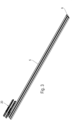
- In den
Figuren 2 und3 ist die Führungsschiene 5 gezeigt, an der an gegenüberliegenden Seiten ein Montageteil 9 oder 10 eingesteckt wird. Diese Montageteile 9 und 10 dienen zur Fixierung eines oder mehrerer Selbsteinzüge 20 oder Anschläge 40, mittels denen eine Endposition einer Schiebetür 6 oder 7 vorgegeben wird. - In den
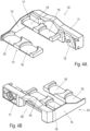
Figuren 4A und 4B ist ein Montageteil 10 im Detail dargestellt. Das Montageteil 10 umfasst einen Montagesteg 11, an dem ein Klemmelement in Form eines Nutensteins 12 gehalten ist. Eine Schraube durchgreift den Montagesteg 11 und den Nutenstein 12, um den Montagesteg 11 nach dem Einschieben in einen Kanal oder eine Nut an der Führungsschiene 5 festzuklemmen. - An dem Montageteil 10 sind ferner zwei Stege 13 und 17 vorgesehen, die in entsprechende Nuten oder Kanäle der Führungsschiene 5 einschiebbar sind. An dem Steg 13 sind zwei Montageelemente 15 und 16 ausgebildet, die in Längsrichtung der Führungsschiene 5 versetzt, also hintereinander, angeordnet sind. An dem Steg 17 sind ebenfalls zwei Montageelemente 18 und 19 vorgesehen, die in Längsrichtung der Führungsschiene 5 gleichfalls versetzt angeordnet sind. Die Montageelemente 15, 16, 18 und 19 sind als topfförmige Aufnahmen ausgebildet, können aber auch durch Stege, Aussparungen oder andere Formkörper gebildet sein. Beide Stege 13 und 17 sind an einer Wand 14 befestigt, die stirnseitig an die Führungsschiene 5 anlegbar ist. Die Stege 13 und 17 weisen eine unterschiedliche Höhe in Relation zu dem Oberboden 3 auf, können aber auch auf gleicher Höhe angeordnet sein.
- In den
Figuren 5A und 5B ist ein weiteres Montageteil 9 gezeigt, das auf der gegenüberliegenden Seite zu dem Montageteil 10 an der Führungsschiene 5 fixiert wird. Das Montageteil 9 umfasst ebenfalls zwei Stege 13 und 17, an denen Montageelemente 15, 16, 18 und 19 vorgesehen sind. Bei dem Montageteil 9 ist allerdings kein Montagesteg 11 mit einem Klemmelement vorgesehen, so dass das Montageteil 9 nur lose in die Führungsschiene 5 eingesteckt werden kann. - Das Montageteil 10 ist über eine kraftschlüssige Fixierung fest an der Führungsschiene 5 angeordnet, während das Montageteil 9 in Längsrichtung der Führungsschiene 5 verschiebbar ist.
- In
Figur 6 ist die Montage von zwei Selbsteinzügen 20 an dem Montageteil 10 gezeigt. Jeder Selbsteinzug 20 umfasst ein längliches Gehäuse 21, an dem eine Führungsbahn 22 für einen Mitnehmer 23 ausgebildet ist. Die Führungsbahn 22 kann linear mit einem abgewinkelten Endabschnitt ausgebildet sein, an dem der Mitnehmer 23 verschwenkt und in einer Parkposition fixiert werden kann. Der Mitnehmer 23 ist über einen Kraftspeicher, insbesondere eine Feder, vorgespannt und kann in eine Einzugsposition mittels einer Dämpfervorrichtung 24 abgebremst werden. Jeder Mitnehmer 23 kann mit einer der Schiebetüren 6 oder 7 gekoppelt werden, um die Schiebetür 6 oder 7 in eine Endposition zu verfahren und dort zu halten. - Um den Selbsteinzug 20 an dem Montageteil 9 oder 10 montieren zu können, ist an dem Gehäuse 21 mindestens ein Klemmelement in Form eines Nutensteins 25 vorgesehen, der in eines der Montageelemente 15, 16, 18 oder 19 eingefügt werden kann und dann durch Drehen an der Führungsschiene 5 klemmend fixiert wird.
- Wie
Figur 6 weiterhin zeigt, kann beispielsweise ein Selbsteinzug 20 für die hintere Schiebetür 6 an einem zu der Wand 14 benachbarten Montageelement 18 an dem Steg 17 positioniert sein, während ein anderer Selbsteinzug 20 für die vordere Schiebetür 7 an einem von der Wand 14 weiter beabstandeten Montageelement 16 an dem Steg 13 positioniert ist. Hierbei liegen in einer Tiefenrichtung des Möbelkorpus 2, also in einer Richtung parallel zur Erstreckung der Wand 14, die Montageelemente 15 bzw. 16 an dem Steg 13 jeweils in einer Flucht mit den Montageelementen 18 bzw. 19 an dem Steg 17. Derart kann je nach Wunsch ein vorher bestimmbarer Türversatz bzw. auch eine Bündigkeit in Richtung senkrecht zur Schieberichtung mindestens zweier Schiebetüren 6, 7 in ihren Endpositionen erreicht werden. - In
Figur 7 ist ein Anschlag 40 gezeigt, der statt eines Selbsteinzuges 20 an einem der Montageteile 9 oder 10 montiert werden kann. Jeder Anschlag 40 umfasst ein Anschlagelement 41, das in dem dargestellten Ausführungsbeispiel als U-förmiger Halter ausgebildet ist, in dem ein Bolzen oder ein anderes Bauteil rastend fixiert werden kann, um eine Schiebetür 6 oder 7 in einer Endposition zu halten. Das Anschlagelement 41 ist an einem Steg 42 gehalten, der endseitig mindestens ein Klemmelement in Form eines Nutensteins 43 aufweist, der, wie zuvor beschrieben, nach der gewünschten Positionierung des Anschlages 40 zu eines der Montageelemente 15, 16, 18 oder 19 durch Drehen klemmend an oder in der Führungsschiene 5 fixiert werden kann. - Je nachdem, in welches der Montageelemente 15 oder 16 bzw. 18 oder 19 der Selbsteinzug 20 oder der Anschlag 40 montiert wird, ist die Endposition der Schiebetür 6 oder 7 voreingestellt. Die Montageelemente 15 und 16 sowie 18 und 19 können beispielsweise einen Abstand zwischen 20 mm und 40 mm aufweisen, um eine Position der Schiebetür vor einer Stirnkante einer Seitenwand 4 oder neben der Seitenwand 4 voreinzustellen. Eine Feinjustage der Endposition kann dann optional über die Laufteile 60 und 70 vorgenommen werden.
- In
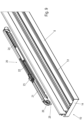
Figur 8 ist die Montage des Montageteils 10 an der Führungsschiene 5 dargestellt. Die Führungsschiene 5 umfasst zwei Laufbahnen 51 und 52, die jeweils an T-förmigen Stegen ausgebildet sind. Auch andere Geometrien für die Laufbahnen 51 und 52 sind natürlich möglich. Die beiden Laufbahnen 51 und 52 sind jeweils zwischen Seitenwänden 53 angeordnet, die vertikal nach oben hervorstehen. - An der Führungsschiene 5 ist seitlich eine Nut 54 vorgesehen, in die ein Bereich mit dem dort einliegenden Nutenstein des Montagesteges 11 eingefügt werden kann. Die Nut 54 ist dabei hinterschnitten mit nach innen ragenden Stegen ausgebildet, die den Montagesteg 11 zumindest bereichsweise umgreifen. Für die Fixierung des Montageteils 10 wird der Montagesteg 11 in die Nut 54 eingeschoben und dann von außen die Schraube mit dem Nutenstein 12 gedreht, bis dieser an den Nutwänden anschlägt und dann klemmend an der Führungsschiene 5 fixiert wird.
- Benachbart zu der Laufbahn 51 ist eine Nut 55 ausgebildet, in die der Steg 13 einfügbar ist. Benachbart zu der Laufbahn 52 ist eine Nut 56 an der Führungsschiene 5 ausgebildet, in die der Steg 17 eingefügt wird. Die Montageelemente 15, 16, 18 und 19 sind nach der Montage des Montageteils 10 von oben zugänglich.
- Um einen Selbsteinzug 20 oder einen Anschlag 40 an dem fixierten Montageteil 10 zu befestigen, wird der Selbsteinzug 20 (
Figur 9 ) oder ein Anschlag 40 von oben in die jeweilige Nut 55 oder 56 eingefügt. Der Monteur kann nun wählen, ob er das Montageelement 15 oder 18 benachbart zu der Wand 14 oder das weiter von der Wand 14 entfernt liegende Montageelement 16 oder 19 nimmt, um den Selbsteinzug 20 zu fixieren. Die Montage erfolgt dergestalt, dass das Gehäuse 21 des Selbsteinzuges 20 in die Nut 55 oder 56 eingesetzt wird und anschließend an dem Montageteil 10 vorpositioniert wird, indem der mindestens eine, an der Unterseite des Gehäuses 21 angeordnete, Nutenstein 25 die vorbestimmte Position in dem Montageelement 15, 16, 17 oder 18 einnimmt. Dann kann der Monteur die mindestens eine Schraube 26 drehen, was in einem ersten Schritt den Nutenstein 25 dreht und an der hinterschnittenen Nut 55 oder 56 gegen ein Anheben sichert. Der mindestens eine Nutenstein 25 ist länglich ausgebildet und kann nur einen gewissen Winkelbereich in der Nut 55 oder 56 gedreht werden, bis es an den Nutwänden anschlägt, so dass dann durch Anziehen der Schraube 26 die nach innen ragenden Stege an der Nut 55 und 56 zwischen dem Gehäuse 21 und dem mindestens einen Nutenstein 25 festgeklemmt werden und der Selbsteinzug 20 so in der gewünschten Position fixiert ist. Nach der Montage des Selbsteinzuges 20 kann nun der zweite Selbsteinzug 20 oder ein Anschlag 40 an der anderen Nut 55 oder 56 fixiert werden. - In
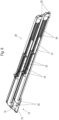
Figur 10 ist eine Führungsschiene 5 bei der Montage an einem Oberboden 3 gezeigt, an dem bereits vier Halter 30 festgelegt sind. Der Möbelkorpus mit dem Oberboden 3 ist dabei nur teilweise dargestellt, und die Führungsschiene 5 kann sich zwischen zwei Seitenwänden 4 erstrecken. An der Führungsschiene 5 ist endseitig ein Montageteil 10 und an der gegenüberliegenden Endseite ein weiteres Montageteil 9 eingesteckt. Ferner sind an der Führungsschiene 5 bereits eine Vielzahl von Selbsteinzügen 20 fixiert, um mindestens eine Schiebetür in einer Schließposition oder einer Öffnungsposition beziehungsweise zwei Schiebetüren beabstandet zueinander zu halten. - Der Aufbau der Halter 30 zur Fixierung der Führungsschiene 5 ist in den
Figuren 11A bis 11C im Detail gezeigt. Jeder Halter 30 umfasst eine Basis 31, die im Wesentlichen plattenförmig ausgebildet ist und an dem Oberboden 3 über Schrauben oder anderen Befestigungsmittel fixiert werden kann, die die Basis 31 durchgreifen. An der Basis 31 ist eine Lageraufnahme 32 ausgebildet, in die ein Verriegelungselement 34 eingefügt werden kann, das im Wesentlichen bolzenförmig ausgebildet ist. Die Basis 31 weist ferner einen oder mehrere Haken 33 auf, die auf der zur Führungsschiene 5 gewandten Seite hervorstehen. - Das Verriegelungselement 34 ist über ein als Hebel ausgebildetes Betätigungselement 35 drehbar, der radial hervorsteht. An dem Verriegelungselement 34 befindet sich ferner eine Aussparung 36, in die ein Vorsprung 38 der Basis 31 eingreift, um das Verriegelungselement 34 in axialer Richtung an der Basis 31 zu sichern. Ferner weist das Verriegelungselement 34 an einem Ende eine Abflachung 37 auf, so dass das Ende nicht zylindrisch ist, sondern an einer Seite über die Abflachung 37 ausspart.
- In
Figur 11B ist eine Montageposition dargestellt, in der die Abflachung 37 nach unten gerichtet ist. Durch Drehen des Betätigungselementes 35 wird das Verriegelungselement 34 in der Lageraufnahme 32 gedreht, so dass die Abflachung 37 zur Seite gedreht wird und im Bereich der Spitze das Verriegelungselement 34 sich nun weiter nach unten erstreckt. - In den
Figuren 12A bis 12C und13A bis 13C ist die Montage der Führungsschiene 5 mit den Selbsteinzügen 20 an einem Halter 30 gezeigt. Der Halter 30 ist an dem Oberboden 3 fixiert, und die Führungsschiene 5 wird entsprechendFigur 12A oder13A parallel zum Oberboden mit lediglich einer Fügerichtung aufgeschoben. An dem Montagesteg 11 des Montageteils 10 ist eine Aussparung 39 vorgesehen, die von den Haken 33 und einem vorderen Ende des Verriegelungselementes 34 durchgriffen werden kann, um in eine Nut 54 der Führungsschiene 5 eingreifen zu können. Nach dem Aufschieben der Führungsschiene 5 ist die in denFiguren 12B und13B gezeigte Position erreicht. Das Verriegelungselement 34 greift mit einem vorderen Ende in die hinterschnittene Nut 54 ein, wobei die Haken 33 einen oberen Steg der Nut 54 hintergreifen und die Abflachung 37 nach unten gerichtet ist, so dass die Führungsschiene 5 in der unverriegelten Position leicht angehoben und abgezogen werden kann. Die Haken 33 greifen in die Aussparung 39 des Montagesteges 11 derart ein, dass jeweils eine ihrer vertikalen Seitenflächen mit nur einem geringen Spiel an die jeweilige äußere seitliche Begrenzungsfläche der Aussparung 39 nahezu zur Anlage kommt. Somit kann eine Bewegung in Längsrichtung der Führungsschiene 5 wirkungsvoll verhindert werden. - Im nächsten Schritt wird nun das Verriegelungselement 34 über das Betätigungselement 35 gedreht, so dass die Abflachung 37 zur Seite gedreht wird und das Verriegelungselement 34 an dem unteren Steg der Nut 54 zur Anlage kommt. Dadurch kann die Führungsschiene 5 nicht mehr angehoben werden, da dies durch das Verriegelungselement 34 blockiert wird, wie dies insbesondere
Figur 12C zeigt. Im Bereich des Montageteils 10 ist somit die Führungsschiene 5 durch einen formschlüssigen Eingriff zwischen der Basis 31 und dem Montagesteg 11 in Längsrichtung der Führungsschiene 5 gesichert, und zudem kann die Führungsschiene 5 auch nicht senkrecht zur Längsrichtung bewegt werden, da dies durch das Eingreifen des Verriegelungselementes 34 und der Haken 33 in die Nut 54 verhindert wird. Statt der dargestellten Nut 54 können auch andere Profilstege eingesetzt werden, um die Führungsschiene 5 in eine Richtung senkrecht zur Längsrichtung der Führungsschiene 5 an einem Halter 30 zu verriegeln. - In
Figur 14 ist die Führungsschiene 5 in einer montierten Position gezeigt. Über die Länge der Führungsschiene 5 verteilt sind vier Halter 30 angeordnet, wobei nur der Halter 30 an dem Montageteil 10 die Führungsschiene 5 in deren Längsrichtung fixiert. Alle Halter 30 hingegen fixieren die Führungsschiene 5 senkrecht zur Längsrichtung gegen ein Anheben oder Verschieben in horizontale Richtung. An der Führungsschiene 5 sind in den Nuten 55, 56 mehrere Selbsteinzüge 20 fixiert, wie dies oben erläutert wurde. Es ist natürlich auch möglich, statt den Selbsteinzügen 20 nur Anschläge 40 an den Montageelementen 15, 16, 18 und 19 vorzusehen. - In den
Figuren 15A bis 15C ist ein modifizierter Halter 30 zur Fixierung einer Führungsschiene 5 gezeigt. Der Halter 30 umfasst eine plattenförmige Basis 31, die an einem Boden oder Oberboden 3 über Schrauben oder anderen Befestigungsmittel fixiert werden kann. An einer Lageraufnahme 32 der Basis 31 ist ein Verriegelungselement 34 drehbar gehalten. An dem Halter 30 sind zwei gegenüber der Basis 31 nach oben hervorstehende Vorsprünge 46 jeweils neben den Haken 33 ausgebildet zur Abstützung der Führungsschiene 5, wobei die Haken 33 analog der ersten Ausführungsvariante gestaltet sind. - Das Verriegelungselement 34 ist über ein als Hebel ausgebildetes, radial hervorstehendes Betätigungselement 35 drehbar in der Lageraufnahme 32 anordenbar. Zur axialen Sicherung ist an dem Verriegelungselement 34 eine Aussparung 36 vorgesehen, in die ein Vorsprung 38 der Basis 31 eingreift, um das Verriegelungselement 34 in axialer Richtung an der Basis 31 zu sichern. Ferner weist das Verriegelungselement 34 an einem Ende eine seitliche Abflachung 37auf. Im Bereich der Abflachung 37 ist weiterhin eine in
Figur 18 erkennbare helixförmige Kurvenführung 45 angeordnet. Das Verriegelungselement 34 weist ferner einen federnden Abschnitt 44 auf, der durch biegbare Stege an einem ansonsten bolzenförmigen Abschnitt an dem Verriegelungselement 34 ausgebildet ist. - In
Figur 15B ist die Montageposition dargestellt, in der die Abflachung 37 nach unten ausgerichtet ist. Durch Drehen des Betätigungselementes 35 wird das Verriegelungselement 34 in der Lageraufnahme 32 gedreht, so dass die Abflachung 37 zur Seite gedreht wird und sich das Verriegelungselement 34 im Bereich der Abflachung 37nun radial weiter nach unten erstreckt (Figur 15C ). Dabei wird auch die helixförmige Kurvenführung 45 andem Verriegelungselement 34 gedreht. - Die Montage der Führungsschiene 5 an einem Halter 30 der
Figur 15 ist in denFiguren 16A und 16B gezeigt. Die Haken 33 sowie eine Spitze des Verriegelungselementes 34, an der die Abflachung 37 sowie die Kurvenführung 45 angeordnet sind, greifen in eine an der Führungsschiene 5 ausgebildete, hinterschnittene Nut 54 ein, wobei die Abflachung 37 nach unten ausgerichtet ist. Sowohl in vertikaler Richtung als auch in horizontaler Richtung senkrecht zur Längsrichtung der Führungsschiene 5 ist in dieser Montageposition Spiel zwischen den Haken 33 und dem Verriegelungselement 34 in Bezug zur Führungsschiene 5. - Für die Festlegung der Führungsschiene 5 an dem Oberboden 3 wird das Verriegelungselement 34 über das Betätigungselement 35 gedreht, bis die in
Figur 16B gezeigte Position erreicht ist. Dadurch wird die Abflachung 37 zur Seite gedreht und das Verriegelungselement 34 hält die Führungsschiene 5 im Wesentlichen spielfrei in vertikaler Richtung, um ein Anheben der Führungsschiene 5 zu unterbinden. Ferner wird die Führungsschiene 5 durch die Kurvenführung 45 auch in Achsrichtung des Verriegelungselementes 34 in Richtung des Halters 30 angezogen. Die Vorsprünge 46 liegen als Drehmomentstützelemente an einer Nutwand 58 der Nut 57 an, die oberhalb der Nut 54 ausgebildet ist. Durch Drehen des Verriegelungselementes 34 kann somit die Führungsschiene 5 klemmend festgelegt werden. Falls durch die Drehung der Kurvenführung 45 eine hohe Anzugskraft auf das Verriegelungselement 34 wirkt, kann der federnde Abschnitt 44 eine gewisse Ausgleichsbewegung in axialer Richtung ausführen. Durch diese mögliche Ausgleichsbewegung lassen sich insbesondere Toleranzen in dem Befestigungssystem ausgleichen, um unerwünschte Spannungen in der Führungsschiene 5 zu vermeiden. - In
Figur 17 ist der Halter 30 mit dem Verriegelungselement 34 in einer Draufsicht ohne die Führungsschiene 5 gezeigt. Hier ist im Besonderen die in einer Wendelform ausgebildete, helixförmige Kurvenführung 45 erkennbar, die wie zuvor beschrieben bei einer Drehung des Verriegelungselementes 34 einen nach innen in die Kurvenführung ragenden Steg in axialer Richtung bewegen und verspannen vermag. - Die
Figur 18 zeigt das Verriegelungselement 34 ohne die Basis 31. Der federnde Abschnitt 44 umfasst eine Vielzahl von gitterförmig angeordneten biegbaren Stegen, die in axialer Richtung des bolzenförmigen Verriegelungselement 34 eine Ausgleichsbewegung ausführen können. - Anstatt des einstückig an dem Verriegelungselement 34 ausgebildeten federnden Abschnittes 44 kann auch ein separat im Bereich der Lageraufnahme 32 eingesetztes Federelement wie zum Beispiel eine Druckfeder oder eine Tellerfeder, dieselbe Aufgabe übernehmen.
-
- 1
- Möbel
- 2
- Möbelkorpus
- 3
- Oberboden
- 4
- Seitenwand
- 5
- Führungsschiene
- 6
- Schiebetür
- 7
- Schiebetür
- 9
- Montageteil
- 10
- Montageteil
- 11
- Montagesteg
- 12
- Nutenstein
- 13
- Steg
- 14
- Wand
- 15
- Montageelement
- 16
- Montageelement
- 17
- Steg
- 18
- Montageelement
- 19
- Montageelement
- 20
- Selbsteinzug
- 21
- Gehäuse
- 22
- Führungsbahn
- 23
- Dämpfervorrichtung
- 24
- Kraftspeicher
- 25
- Nutenstein
- 26
- Schraube
- 30
- Halter
- 31
- Basis
- 32
- Lageraufnahme
- 33
- Haken
- 34
- Verriegelungselement
- 35
- Betätigungselement
- 36
- Aussparung
- 37
- Abflachung
- 38
- Vorsprung
- 39
- Aussparung
- 40
- Anschlag
- 41
- Anschlagelement
- 42
- Steg
- 43
- Nutenstein
- 44
- federnder Abschnitt
- 45
- Kurvenführung
- 46
- Vorsprung
- 51
- Laufbahn
- 52
- Laufbahn
- 53
- Seitenwand
- 54
- Nut
- 55
- Nut
- 56
- Nut
- 57
- Nut
- 58
- Nutwand
- 60
- Laufteil
- 70
- Laufteil
Claims (16)
- Führungsvorrichtung für eine Schiebetür (6, 7), mit einer Führungsschiene (5), die mindestens eine Laufbahn (51, 52) für ein verfahrbares Laufteil (60, 70) aufweist, wobei in die Führungsschiene (5) an gegenüberliegenden Stirnseiten ein Montageteil (9, 10) eingesteckt ist, und an jedem Montageteil (9, 10) ein Anschlag (40) und/oder ein Selbsteinzug (20) montiert ist, wobei mindestens ein Montageteil (9, 10) über einen Halter (30) der Führungsvorrichtung an einem Oberboden (3) oder Boden fixierbar ist, wobei in montierter Stellung ein erster Halter (30) der Führungsvorrichtung das eine Montageteil (10) in Längsrichtung der Führungsschiene (5) und senkrecht hierzu fixiert und ein zweiter Halter (30) der Führungsvorrichtung die Führungsschiene (5) oder das andere Montageteil (9) senkrecht zur Längsrichtung der Führungsschiene (5) fixiert und in Längsrichtung der Führungsschiene (5) verschiebbar hält, dadurch gekennzeichnet, dass der Anschlag (40) oder der Selbsteinzug (20) an einer Nut (55, 56) der Führungsschiene (5) über mindestens einen Nutenstein (25, 43) festgelegt ist.
- Führungsvorrichtung nach Anspruch 1, dadurch gekennzeichnet, dass der erste Halter (30) in der Montagestellung das eine Montageteil (10) in Längsrichtung der Führungsschiene (5) und senkrecht hierzu parallel zum Oberboden (3) oder Boden fixiert.
- Führungsvorrichtung nach Anspruch 1 oder 2, dadurch gekennzeichnet, dass die Halter (30) ein Verriegelungselement (34) zum Fixieren der Montageteile (9, 10) und/oder der Führungsschiene (5) aufweisen.
- Führungsvorrichtung nach Anspruch 3, dadurch gekennzeichnet, dass das Verriegelungselement (34) über ein Betätigungselement (35) des jeweiligen Halters (30) betätigbar ist.
- Führungsvorrichtung nach Anspruch 3, dadurch gekennzeichnet, dass jeder Halter (30) eine an einem Boden oder Oberboden (3) festlegbare Basis (31) und das über das Betätigungselement (35) bewegbare Verriegelungselement (34) aufweist, das mit einem Endabschnitt an einem Steg oder in einer weiteren Nut der (54) Führungsschiene (5) festlegbar ist.
- Führungsvorrichtung nach Anspruch 5, dadurch gekennzeichnet, dass die Basis (31) mit mindestens einem Haken (33) in die als hinterschnittene Nut ausgeführte weitere Nut (54) der Führungsschiene (5) eingreifen kann und das Verriegelungselement (34) in einer Verriegelungsposition den mindestens einen Haken (33) in der weiteren Nut (54) sichern kann.
- Führungsvorrichtung nach Anspruch 5, dadurch gekennzeichnet, dass an jedem Halter (30) mindestens ein gegenüber der Basis (31) nach oben hervorstehender Vorsprung (46) ausgebildet ist, der sich an einem vertikalen und/oder einem horizontalen Wandabschnitt der Führungsschiene (5) abstützen kann.
- Führungsvorrichtung nach Anspruch 5 oder 6, dadurch gekennzeichnet, dass das Verriegelungselement (34) eine Kurvenführung (45) aufweist, mittels der bei einem Verschwenken oder Verschieben des Verriegelungselementes (34) die Führungsschiene (5) klemmend festlegbar ist.
- Führungsvorrichtung nach einem der vorhergehenden Ansprüche 3-8, dadurch gekennzeichnet, dass das Verriegelungselement (34) mit mindestens einem federnden Element zusammen wirkt oder daran einstückig mindestens ein federnder Abschnitt (44) ausgebildet ist.
- Führungsvorrichtung nach einem der vorhergehenden Ansprüche,
dadurch gekennzeichnet, dass in der Montagestellung das eine Montageteil (10) mit der Fixierung in Längsrichtung der Führungsschiene (5) einen sich in Längsrichtung erstreckenden Montagesteg (11) aufweist, der formschlüssig mit dem ersten Halter (30) in Eingriff steht. - Führungsvorrichtung nach einem der vorhergehenden Ansprüche,
dadurch gekennzeichnet, dass jedes Montageteil (9, 10) mindestens ein Montageelement (15, 16, 18, 19) zur Fixierung des Anschlages (40) oder des Selbsteinzuges (20) aufweist und die Montageelemente (15, 16, 18, 19) an Stegen (13, 17) der Montageteile angeordnet sind, die in die Führungsschiene (5) eingeschoben sind. - Führungsvorrichtung nach Anspruch 11,
dadurch gekennzeichnet, dass die Montageelemente (15, 16, 18, 19) als Aufnahmen ausgebildet sind, in die ein Klemmelement des Anschlages (40) oder des Selbsteinzuges zur Fixierung des Anschlages (40) oder des Selbsteinzuges (20) einsteckbar ist. - Führungsvorrichtung nach einem der vorhergehenden Ansprüche 11 oder 12, dadurch gekennzeichnet, dass jedes Montageteil (9, 10) einen Wandabschnitt (14) aufweist, der stirnseitig an der Führungsschiene (5) angelegt ist, wobei eine Nut (55, 56) der Führungsschiene (5) zur Aufnahme mindestens eines Montageelementes (15, 16, 18, 19) benachbart zu einer Laufbahn (51, 52) an der Führungsschiene (5) angeordnet ist.
- Verfahren zur Montage einer Führungsschiene (5) einer Führungsvorrichtung für eine Schiebetür (6, 7), mit den folgenden Schritten:- Fixieren mehrerer Halter (30) an einem Boden oder Oberboden (3) eines Schrankmöbels (1);- Einstecken eines ersten Montageteils (10) an einer Stirnseite der Führungsschiene (5);- Einstecken eines zweiten Montageteils (9) an einer gegenüberliegenden Stirnseite der Führungsschiene (5);- Positionieren der Führungsschiene (5) an den Haltern (30);- Festlegen des ersten Montageteils (10) an der Führungsschiene (5), und- Verriegeln der Halter (30) derart, dass die Führungsschiene (5) an dem ersten Montageteil (10) in Längsrichtung und senkrecht zur Längsrichtung der Führungsschiene (5) fixiert ist und an dem anderen Halter (30) nur ein Fixieren senkrecht zur Längsrichtung der Führungsschiene (5) erfolgt- dadurch gekennzeichnet, dass ein Anschlag (40) oder ein Selbsteinzug (20) an einer Nut (55, 56) der Führungsschiene (5) über mindestens einen Nutenstein (25, 43) festlegt wird.
- Verfahren nach Anspruch 14, dadurch gekennzeichnet, dass die Halter (30) jeweils ein Verriegelungselement (34) aufweisen, das mit einem Ende in eine weitere Nut (54) der Führungsschiene (5) eingreift.
- Verfahren nach Anspruch 14 oder 15, dadurch gekennzeichnet, dass über die Führungsschiene (5) verteilt mindestens zwei Halter (30) montiert werden.
Applications Claiming Priority (2)
| Application Number | Priority Date | Filing Date | Title |
|---|---|---|---|
| DE102018112026.5A DE102018112026A1 (de) | 2018-05-18 | 2018-05-18 | Führungsvorrichtung für eine Schiebetür und Verfahren zur Montage einer Führungsschiene |
| PCT/EP2019/062803 WO2019219910A1 (de) | 2018-05-18 | 2019-05-17 | Führungsvorrichtung für eine schiebetür und verfahren zur montage einer führungsschiene |
Publications (2)
| Publication Number | Publication Date |
|---|---|
| EP3794193A1 EP3794193A1 (de) | 2021-03-24 |
| EP3794193B1 true EP3794193B1 (de) | 2024-12-25 |
Family
ID=66597609
Family Applications (1)
| Application Number | Title | Priority Date | Filing Date |
|---|---|---|---|
| EP19725145.7A Active EP3794193B1 (de) | 2018-05-18 | 2019-05-17 | Führungsvorrichtung für eine schiebetür und verfahren zur montage einer führungsschiene |
Country Status (4)
| Country | Link |
|---|---|
| EP (1) | EP3794193B1 (de) |
| CN (1) | CN112166234B (de) |
| DE (1) | DE102018112026A1 (de) |
| WO (1) | WO2019219910A1 (de) |
Families Citing this family (2)
| Publication number | Priority date | Publication date | Assignee | Title |
|---|---|---|---|---|
| IT201700008876A1 (it) * | 2017-01-27 | 2018-07-27 | Terno Scorrevoli S P A Unipersonale | Dispositivo per lo scorrimento e la frenatura di porte scorrevoli e ante |
| IT202200007370A1 (it) | 2022-04-13 | 2023-10-13 | Terno Scorrevoli S P A Unipersonale | Dispositivo per l’aggancio e la regolazione di accessori lungo profili di supporto |
Family Cites Families (10)
| Publication number | Priority date | Publication date | Assignee | Title |
|---|---|---|---|---|
| GB2407965A (en) * | 2003-11-14 | 2005-05-18 | Cairns Michael Paul | Curtain pole hanging bracket and system |
| ITMI20072168A1 (it) * | 2007-11-14 | 2009-05-15 | Agostino Ferrari Spa | "sistema di chiusura controllata per elementi scorrevoli di mobilio" |
| IT1392935B1 (it) | 2009-02-23 | 2012-04-02 | Caimi Export Spa | Dispositivo per la movimentazione di ante scorrevoli |
| IT1401802B1 (it) * | 2010-10-19 | 2013-08-28 | Bortoluzzi Lab S R L | Sistema di fissaggio a scatto delle guide, particolarmente per porte scorrevoli di mobili |
| JP6082590B2 (ja) * | 2012-12-26 | 2017-02-15 | 磯川産業株式会社 | 引戸用ランナー構造 |
| CN203503951U (zh) * | 2013-10-25 | 2014-03-26 | 深圳市奥普利斯光电有限公司 | 可滑动的调光膜导电装置 |
| DE102014109429B4 (de) * | 2014-07-07 | 2026-01-22 | Hettich-Heinze Gmbh & Co. Kg | Beschlag für eine Schiebetür |
| DE102014114339A1 (de) * | 2014-10-02 | 2016-04-07 | Hettich-Heinze Gmbh & Co. Kg | Führungseinrichtung zur Führung einer Schiebetür und Schrankmöbel |
| DE102015114392A1 (de) * | 2015-08-28 | 2017-03-02 | Hettich-Heinze Gmbh & Co. Kg | Vorrichtung zum Positionieren von zwei Schiebetüren und Möbel |
| WO2018162320A1 (de) * | 2017-03-08 | 2018-09-13 | Hettich-Heinze Gmbh & Co. Kg | Montageeinheit und verfahren zur montage einer führungsschiene an einem oberboden oder boden eines möbels |
-
2018
- 2018-05-18 DE DE102018112026.5A patent/DE102018112026A1/de active Pending
-
2019
- 2019-05-17 CN CN201980032653.9A patent/CN112166234B/zh active Active
- 2019-05-17 EP EP19725145.7A patent/EP3794193B1/de active Active
- 2019-05-17 WO PCT/EP2019/062803 patent/WO2019219910A1/de not_active Ceased
Also Published As
| Publication number | Publication date |
|---|---|
| CN112166234B (zh) | 2022-09-02 |
| WO2019219910A1 (de) | 2019-11-21 |
| CN112166234A (zh) | 2021-01-01 |
| EP3794193A1 (de) | 2021-03-24 |
| DE102018112026A1 (de) | 2019-11-21 |
Similar Documents
| Publication | Publication Date | Title |
|---|---|---|
| DE202018102084U1 (de) | Vorrichtung zur Bewegung eines an einem Möbelkorpus eines Möbels aufgenommenen Möbelteils | |
| EP1916361A1 (de) | Griff zur Montage in einem Durchbruch | |
| EP3713448B1 (de) | Vorrichtung zum festlegen eines schubelementes und möbel | |
| EP0940067A2 (de) | Schaltschrank mit einer montageplatte | |
| EP3105397A1 (de) | Beschlag für eine schiebetür | |
| EP3859110B1 (de) | Schiebetürbeschlag und verfahren zum bewegen einer steuereinrichtung | |
| EP3859107B1 (de) | Schiebetür | |
| WO2012110373A1 (de) | Vorrichtung zur verriegelung relativ zueinander beweglicher teile | |
| EP3742931B1 (de) | Ausziehführung für einen schubkasten und verfahren zum ausrichten eines schubkastens an einer ausziehführung | |
| EP3954852B1 (de) | Führungsvorrichtung und möbel | |
| EP3859105B1 (de) | Schliesseinrichtung | |
| EP1716778B1 (de) | Schublade für einen freistehenden Korpus, welche beidseitig ausziehbar ist | |
| WO2019219910A1 (de) | Führungsvorrichtung für eine schiebetür und verfahren zur montage einer führungsschiene | |
| EP3569804B1 (de) | Führungsvorrichtung für eine schiebetür | |
| EP3464767B1 (de) | Führungseinrichtung für ein schiebeelement, möbel und verfahren zur montage eines schiebeelementes | |
| WO2024016032A1 (de) | Schubladenseitenwand für eine schublade | |
| EP1775482A1 (de) | Schnellbefestigungselement | |
| EP4263990A1 (de) | Lagerungsvorrichtung zur lagerung wenigstens eines türflügels | |
| EP0063294B1 (de) | Befestigungsvorrichtung, insbesondere für Armlehnen oder Haltegriffe an der Karosseriewand von Fahrzeugen | |
| DE69002342T2 (de) | Befestigungsvorrichtung durch Zusammenschrauben auf einem Profil, insbesondere auf einem Elektrizitätsschrank. | |
| DE102020114807A1 (de) | Möbel | |
| EP4184731B1 (de) | Montageelement für den innenausbau eines schaltschrankgehäuses und eine entsprechende schaltschrankanordnung | |
| DE10319955B4 (de) | Verstelleinrichtung | |
| WO2018210901A1 (de) | Möbel und verfahren zur montage eines schiebeelementes an einem möbelkorpus | |
| EP3256677B1 (de) | Beschlag für mindestens einen linear verfahrbaren flügel und möbel |
Legal Events
| Date | Code | Title | Description |
|---|---|---|---|
| STAA | Information on the status of an ep patent application or granted ep patent |
Free format text: STATUS: UNKNOWN |
|
| STAA | Information on the status of an ep patent application or granted ep patent |
Free format text: STATUS: THE INTERNATIONAL PUBLICATION HAS BEEN MADE |
|
| PUAI | Public reference made under article 153(3) epc to a published international application that has entered the european phase |
Free format text: ORIGINAL CODE: 0009012 |
|
| STAA | Information on the status of an ep patent application or granted ep patent |
Free format text: STATUS: REQUEST FOR EXAMINATION WAS MADE |
|
| 17P | Request for examination filed |
Effective date: 20201126 |
|
| AK | Designated contracting states |
Kind code of ref document: A1 Designated state(s): AL AT BE BG CH CY CZ DE DK EE ES FI FR GB GR HR HU IE IS IT LI LT LU LV MC MK MT NL NO PL PT RO RS SE SI SK SM TR |
|
| AX | Request for extension of the european patent |
Extension state: BA ME |
|
| DAV | Request for validation of the european patent (deleted) | ||
| DAX | Request for extension of the european patent (deleted) | ||
| GRAP | Despatch of communication of intention to grant a patent |
Free format text: ORIGINAL CODE: EPIDOSNIGR1 |
|
| STAA | Information on the status of an ep patent application or granted ep patent |
Free format text: STATUS: GRANT OF PATENT IS INTENDED |
|
| INTG | Intention to grant announced |
Effective date: 20240807 |
|
| GRAS | Grant fee paid |
Free format text: ORIGINAL CODE: EPIDOSNIGR3 |
|
| GRAA | (expected) grant |
Free format text: ORIGINAL CODE: 0009210 |
|
| STAA | Information on the status of an ep patent application or granted ep patent |
Free format text: STATUS: THE PATENT HAS BEEN GRANTED |
|
| AK | Designated contracting states |
Kind code of ref document: B1 Designated state(s): AL AT BE BG CH CY CZ DE DK EE ES FI FR GB GR HR HU IE IS IT LI LT LU LV MC MK MT NL NO PL PT RO RS SE SI SK SM TR |
|
| P01 | Opt-out of the competence of the unified patent court (upc) registered |
Free format text: CASE NUMBER: APP_61609/2024 Effective date: 20241118 |
|
| REG | Reference to a national code |
Ref country code: GB Ref legal event code: FG4D Free format text: NOT ENGLISH |
|
| REG | Reference to a national code |
Ref country code: CH Ref legal event code: EP |
|
| REG | Reference to a national code |
Ref country code: DE Ref legal event code: R096 Ref document number: 502019012691 Country of ref document: DE |
|
| REG | Reference to a national code |
Ref country code: IE Ref legal event code: FG4D Free format text: LANGUAGE OF EP DOCUMENT: GERMAN |
|
| REG | Reference to a national code |
Ref country code: LT Ref legal event code: MG9D |
|
| PG25 | Lapsed in a contracting state [announced via postgrant information from national office to epo] |
Ref country code: FI Free format text: LAPSE BECAUSE OF FAILURE TO SUBMIT A TRANSLATION OF THE DESCRIPTION OR TO PAY THE FEE WITHIN THE PRESCRIBED TIME-LIMIT Effective date: 20241225 |
|
| PG25 | Lapsed in a contracting state [announced via postgrant information from national office to epo] |
Ref country code: BG Free format text: LAPSE BECAUSE OF FAILURE TO SUBMIT A TRANSLATION OF THE DESCRIPTION OR TO PAY THE FEE WITHIN THE PRESCRIBED TIME-LIMIT Effective date: 20241225 |
|
| PG25 | Lapsed in a contracting state [announced via postgrant information from national office to epo] |
Ref country code: NO Free format text: LAPSE BECAUSE OF FAILURE TO SUBMIT A TRANSLATION OF THE DESCRIPTION OR TO PAY THE FEE WITHIN THE PRESCRIBED TIME-LIMIT Effective date: 20250325 |
|
| PG25 | Lapsed in a contracting state [announced via postgrant information from national office to epo] |
Ref country code: LV Free format text: LAPSE BECAUSE OF FAILURE TO SUBMIT A TRANSLATION OF THE DESCRIPTION OR TO PAY THE FEE WITHIN THE PRESCRIBED TIME-LIMIT Effective date: 20241225 Ref country code: GR Free format text: LAPSE BECAUSE OF FAILURE TO SUBMIT A TRANSLATION OF THE DESCRIPTION OR TO PAY THE FEE WITHIN THE PRESCRIBED TIME-LIMIT Effective date: 20250326 |
|
| PG25 | Lapsed in a contracting state [announced via postgrant information from national office to epo] |
Ref country code: RS Free format text: LAPSE BECAUSE OF FAILURE TO SUBMIT A TRANSLATION OF THE DESCRIPTION OR TO PAY THE FEE WITHIN THE PRESCRIBED TIME-LIMIT Effective date: 20250325 |
|
| REG | Reference to a national code |
Ref country code: NL Ref legal event code: MP Effective date: 20241225 |
|
| PG25 | Lapsed in a contracting state [announced via postgrant information from national office to epo] |
Ref country code: NL Free format text: LAPSE BECAUSE OF FAILURE TO SUBMIT A TRANSLATION OF THE DESCRIPTION OR TO PAY THE FEE WITHIN THE PRESCRIBED TIME-LIMIT Effective date: 20241225 |
|
| PG25 | Lapsed in a contracting state [announced via postgrant information from national office to epo] |
Ref country code: SM Free format text: LAPSE BECAUSE OF FAILURE TO SUBMIT A TRANSLATION OF THE DESCRIPTION OR TO PAY THE FEE WITHIN THE PRESCRIBED TIME-LIMIT Effective date: 20241225 |
|
| PG25 | Lapsed in a contracting state [announced via postgrant information from national office to epo] |
Ref country code: PL Free format text: LAPSE BECAUSE OF FAILURE TO SUBMIT A TRANSLATION OF THE DESCRIPTION OR TO PAY THE FEE WITHIN THE PRESCRIBED TIME-LIMIT Effective date: 20241225 |
|
| PGFP | Annual fee paid to national office [announced via postgrant information from national office to epo] |
Ref country code: DE Payment date: 20250519 Year of fee payment: 7 |
|
| PG25 | Lapsed in a contracting state [announced via postgrant information from national office to epo] |
Ref country code: ES Free format text: LAPSE BECAUSE OF FAILURE TO SUBMIT A TRANSLATION OF THE DESCRIPTION OR TO PAY THE FEE WITHIN THE PRESCRIBED TIME-LIMIT Effective date: 20241225 |
|
| PG25 | Lapsed in a contracting state [announced via postgrant information from national office to epo] |
Ref country code: IS Free format text: LAPSE BECAUSE OF FAILURE TO SUBMIT A TRANSLATION OF THE DESCRIPTION OR TO PAY THE FEE WITHIN THE PRESCRIBED TIME-LIMIT Effective date: 20250425 |
|
| PGFP | Annual fee paid to national office [announced via postgrant information from national office to epo] |
Ref country code: IT Payment date: 20250530 Year of fee payment: 7 |
|
| PG25 | Lapsed in a contracting state [announced via postgrant information from national office to epo] |
Ref country code: PT Free format text: LAPSE BECAUSE OF FAILURE TO SUBMIT A TRANSLATION OF THE DESCRIPTION OR TO PAY THE FEE WITHIN THE PRESCRIBED TIME-LIMIT Effective date: 20250428 |
|
| PG25 | Lapsed in a contracting state [announced via postgrant information from national office to epo] |
Ref country code: EE Free format text: LAPSE BECAUSE OF FAILURE TO SUBMIT A TRANSLATION OF THE DESCRIPTION OR TO PAY THE FEE WITHIN THE PRESCRIBED TIME-LIMIT Effective date: 20241225 |
|
| PGFP | Annual fee paid to national office [announced via postgrant information from national office to epo] |
Ref country code: CH Payment date: 20250601 Year of fee payment: 7 |
|
| PG25 | Lapsed in a contracting state [announced via postgrant information from national office to epo] |
Ref country code: RO Free format text: LAPSE BECAUSE OF FAILURE TO SUBMIT A TRANSLATION OF THE DESCRIPTION OR TO PAY THE FEE WITHIN THE PRESCRIBED TIME-LIMIT Effective date: 20241225 |
|
| PG25 | Lapsed in a contracting state [announced via postgrant information from national office to epo] |
Ref country code: SK Free format text: LAPSE BECAUSE OF FAILURE TO SUBMIT A TRANSLATION OF THE DESCRIPTION OR TO PAY THE FEE WITHIN THE PRESCRIBED TIME-LIMIT Effective date: 20241225 |
|
| PG25 | Lapsed in a contracting state [announced via postgrant information from national office to epo] |
Ref country code: CZ Free format text: LAPSE BECAUSE OF FAILURE TO SUBMIT A TRANSLATION OF THE DESCRIPTION OR TO PAY THE FEE WITHIN THE PRESCRIBED TIME-LIMIT Effective date: 20241225 |
|
| PG25 | Lapsed in a contracting state [announced via postgrant information from national office to epo] |
Ref country code: SE Free format text: LAPSE BECAUSE OF FAILURE TO SUBMIT A TRANSLATION OF THE DESCRIPTION OR TO PAY THE FEE WITHIN THE PRESCRIBED TIME-LIMIT Effective date: 20241225 |
|
| REG | Reference to a national code |
Ref country code: DE Ref legal event code: R097 Ref document number: 502019012691 Country of ref document: DE |
|
| PG25 | Lapsed in a contracting state [announced via postgrant information from national office to epo] |
Ref country code: DK Free format text: LAPSE BECAUSE OF FAILURE TO SUBMIT A TRANSLATION OF THE DESCRIPTION OR TO PAY THE FEE WITHIN THE PRESCRIBED TIME-LIMIT Effective date: 20241225 |
|
| PLBE | No opposition filed within time limit |
Free format text: ORIGINAL CODE: 0009261 |
|
| STAA | Information on the status of an ep patent application or granted ep patent |
Free format text: STATUS: NO OPPOSITION FILED WITHIN TIME LIMIT |
|
| 26N | No opposition filed |
Effective date: 20250926 |
|
| PG25 | Lapsed in a contracting state [announced via postgrant information from national office to epo] |
Ref country code: LU Free format text: LAPSE BECAUSE OF NON-PAYMENT OF DUE FEES Effective date: 20250517 |
|
| GBPC | Gb: european patent ceased through non-payment of renewal fee |
Effective date: 20250517 |
|
| REG | Reference to a national code |
Ref country code: BE Ref legal event code: MM Effective date: 20250531 |
|
| PG25 | Lapsed in a contracting state [announced via postgrant information from national office to epo] |
Ref country code: MC Free format text: LAPSE BECAUSE OF FAILURE TO SUBMIT A TRANSLATION OF THE DESCRIPTION OR TO PAY THE FEE WITHIN THE PRESCRIBED TIME-LIMIT Effective date: 20241225 |
|
| PG25 | Lapsed in a contracting state [announced via postgrant information from national office to epo] |
Ref country code: GB Free format text: LAPSE BECAUSE OF NON-PAYMENT OF DUE FEES Effective date: 20250517 |
|
| PG25 | Lapsed in a contracting state [announced via postgrant information from national office to epo] |
Ref country code: IE Free format text: LAPSE BECAUSE OF NON-PAYMENT OF DUE FEES Effective date: 20250517 |
|
| PG25 | Lapsed in a contracting state [announced via postgrant information from national office to epo] |
Ref country code: HR Free format text: LAPSE BECAUSE OF FAILURE TO SUBMIT A TRANSLATION OF THE DESCRIPTION OR TO PAY THE FEE WITHIN THE PRESCRIBED TIME-LIMIT Effective date: 20241225 |
|
| PG25 | Lapsed in a contracting state [announced via postgrant information from national office to epo] |
Ref country code: BE Free format text: LAPSE BECAUSE OF NON-PAYMENT OF DUE FEES Effective date: 20250531 |
|
| PG25 | Lapsed in a contracting state [announced via postgrant information from national office to epo] |
Ref country code: FR Free format text: LAPSE BECAUSE OF NON-PAYMENT OF DUE FEES Effective date: 20250531 |