EP3792009B1 - Appareil de travail portatif doté d'un outil - Google Patents
Appareil de travail portatif doté d'un outil Download PDFInfo
- Publication number
- EP3792009B1 EP3792009B1 EP20197561.2A EP20197561A EP3792009B1 EP 3792009 B1 EP3792009 B1 EP 3792009B1 EP 20197561 A EP20197561 A EP 20197561A EP 3792009 B1 EP3792009 B1 EP 3792009B1
- Authority
- EP
- European Patent Office
- Prior art keywords
- locking lever
- lever
- spring
- axis
- locking
- Prior art date
- Legal status (The legal status is an assumption and is not a legal conclusion. Google has not performed a legal analysis and makes no representation as to the accuracy of the status listed.)
- Active
Links
- 230000000903 blocking effect Effects 0.000 claims 21
- 210000003813 thumb Anatomy 0.000 description 18
- 239000013598 vector Substances 0.000 description 6
- 230000036316 preload Effects 0.000 description 5
- 230000002093 peripheral effect Effects 0.000 description 4
- 210000003811 finger Anatomy 0.000 description 3
- 238000002485 combustion reaction Methods 0.000 description 2
- 238000009434 installation Methods 0.000 description 2
- 238000000034 method Methods 0.000 description 2
- 238000005452 bending Methods 0.000 description 1
- 230000015572 biosynthetic process Effects 0.000 description 1
- 230000007423 decrease Effects 0.000 description 1
- 230000005484 gravity Effects 0.000 description 1
- 210000004247 hand Anatomy 0.000 description 1
- 230000000284 resting effect Effects 0.000 description 1
- 230000003068 static effect Effects 0.000 description 1
- 238000004804 winding Methods 0.000 description 1
- 239000002023 wood Substances 0.000 description 1
- 210000000707 wrist Anatomy 0.000 description 1
Images


Classifications
-
- B—PERFORMING OPERATIONS; TRANSPORTING
- B23—MACHINE TOOLS; METAL-WORKING NOT OTHERWISE PROVIDED FOR
- B23Q—DETAILS, COMPONENTS, OR ACCESSORIES FOR MACHINE TOOLS, e.g. ARRANGEMENTS FOR COPYING OR CONTROLLING; MACHINE TOOLS IN GENERAL CHARACTERISED BY THE CONSTRUCTION OF PARTICULAR DETAILS OR COMPONENTS; COMBINATIONS OR ASSOCIATIONS OF METAL-WORKING MACHINES, NOT DIRECTED TO A PARTICULAR RESULT
- B23Q5/00—Driving or feeding mechanisms; Control arrangements therefor
- B23Q5/54—Arrangements or details not restricted to group B23Q5/02 or group B23Q5/22 respectively, e.g. control handles
- B23Q5/58—Safety devices
-
- B—PERFORMING OPERATIONS; TRANSPORTING
- B25—HAND TOOLS; PORTABLE POWER-DRIVEN TOOLS; MANIPULATORS
- B25F—COMBINATION OR MULTI-PURPOSE TOOLS NOT OTHERWISE PROVIDED FOR; DETAILS OR COMPONENTS OF PORTABLE POWER-DRIVEN TOOLS NOT PARTICULARLY RELATED TO THE OPERATIONS PERFORMED AND NOT OTHERWISE PROVIDED FOR
- B25F5/00—Details or components of portable power-driven tools not particularly related to the operations performed and not otherwise provided for
- B25F5/02—Construction of casings, bodies or handles
-
- A—HUMAN NECESSITIES
- A01—AGRICULTURE; FORESTRY; ANIMAL HUSBANDRY; HUNTING; TRAPPING; FISHING
- A01G—HORTICULTURE; CULTIVATION OF VEGETABLES, FLOWERS, RICE, FRUIT, VINES, HOPS OR SEAWEED; FORESTRY; WATERING
- A01G3/00—Cutting implements specially adapted for horticultural purposes; Delimbing standing trees
- A01G3/04—Apparatus for trimming hedges, e.g. hedge shears
- A01G3/047—Apparatus for trimming hedges, e.g. hedge shears portable
- A01G3/053—Apparatus for trimming hedges, e.g. hedge shears portable motor-driven
-
- B—PERFORMING OPERATIONS; TRANSPORTING
- B27—WORKING OR PRESERVING WOOD OR SIMILAR MATERIAL; NAILING OR STAPLING MACHINES IN GENERAL
- B27B—SAWS FOR WOOD OR SIMILAR MATERIAL; COMPONENTS OR ACCESSORIES THEREFOR
- B27B17/00—Chain saws; Equipment therefor
- B27B17/08—Drives or gearings; Devices for swivelling or tilting the chain saw
Definitions
- the invention relates to a hand-held working device with a tool.
- Hand-held tools are known in which the operating lever for operating a drive motor is locked by a safety device, such as a locking lever.
- a safety device such as a locking lever.
- the locking lever and the operating lever must therefore be pressed one after the other or at least simultaneously.
- the arrangement of the levers is usually chosen so that the operator can press both levers with just one hand.
- the disadvantage of such tools is that operating both levers at the same time is often uncomfortable and not very intuitive. The operator may even have to give up his firm hand position on the handle of the tool in order to be able to press both levers at the same time.
- a router with a locking lever is known, wherein the locking lever has a single wing element.
- the invention is based on the object of developing a hand-held working device in such a way that ergonomic operation of the working device is made possible for the operator.
- the locking lever has three wing elements for actuating the locking lever. This allows the operator to actuate the locking lever in an ergonomic manner even when the tool is held sideways.
- a sideways grip position is common, for example, with hedge trimmers. If, for example, a hedge is cut along its horizontally aligned top side, the operator must move the hedge trimmer in a horizontal plane. To do this, the operator usually holds the hedge trimmer in an upper grip position. If the operator cuts the hedge on its vertical sides, the operator will move the hedge trimmer up and down in a vertical plane and rotate the hedge trimmer sideways so that the cutting tool of the hedge trimmer is also aligned parallel to the sides of the hedge.
- the operator usually holds the hedge trimmer rotated by 90° around the longitudinal axis of the handle compared to the upper grip position. With such a grip position, it is difficult for the operator to operate the locking lever with conventional tools.
- the three wing elements arranged on the locking lever allow the operator to easily operate the locking lever in any grip position. This type of locking lever design can also be advantageous for other tools that require different grip positions.
- one of the three wing elements is an upper wing element.
- the upper wing element is advantageously arranged on the locking lever opposite the actuating lever with respect to the rotation axis of the locking lever.
- the upper wing element is preferably located in the longitudinal plane of the handle in the locking position of the locking lever.
- two of the three wing elements are lateral wing elements, wherein the two lateral wing elements of the locking lever are arranged opposite one another on the locking lever with respect to the longitudinal plane of the handle.
- the lateral wing elements can be arranged offset from one another in a direction parallel to the rotation axis of the locking lever and/or in a direction that runs parallel to the longitudinal plane and perpendicular to the rotation axis.
- the lateral wing elements are in the locking position of the locking lever are arranged symmetrically to one another with respect to the longitudinal plane.
- the two lateral wing elements of the locking lever are at the same angular distance around the axis of rotation of the locking lever to the upper wing element.
- the lateral wing elements are preferably arranged symmetrically to the upper wing element.
- the angular distance is at least 60°, preferably at least 90°.
- the wing elements arranged on the sides mean that the implement can be gripped with both the right and left hand and the locking lever can be operated.
- the upper wing element ensures ergonomic operation of the locking lever, particularly when the implement is held sideways.
- the longitudinal axis of the handle forms an angle with the axis of rotation of the locking lever in the direction of view perpendicular to the longitudinal plane, wherein the angle lies in a range of 10° to 60°.
- the operator When operating the implement, the operator holds the implement firmly by its handle. In this hand position, the operator is able to move the thumb and at least the index finger freely.
- the locking lever and operating lever are advantageously arranged in such a way that the locking lever can be pressed with the thumb and the thus unlocked operating lever can then be operated with the index finger or another free finger.
- the preferred arrangement of the longitudinal axis of the handle and the rotation axis of the locking lever allows operation with a pure swinging movement of the thumb relative to the hand. A movement of the thumb in the longitudinal direction can thus be avoided. If the rotation axis of the locking lever is arranged parallel to the longitudinal axis of the handle, the thumb could slip off the locking lever during a swinging movement. To avoid this, the operator would have to move his thumb forwards in the longitudinal direction. to the locking lever, which would require the operator to give up his firm hand position on the handle of the implement.
- the locking lever can be operated by the thumb as part of the natural pivoting movement of the thumb. Compensating for the thumb movement by moving in the longitudinal direction of the handle is not necessary. Ergonomic operation of the locking lever and ergonomic use of the tool are possible.
- the angle is preferably in a range of 15° to 45°. This enables particularly ergonomic operation.
- the longitudinal axis is a tangent to the center line of the handle.
- the tangent is on the center line at the front end of the handle.
- the center line runs through the centroids of the individual cross-sectional planes of the handle that are parallel to one another.
- a spring unit for the locking lever interacts with a contour on the locking lever, the contour extending over an angular section around the rotation axis of the locking lever and having a lower section formed in the direction of the rotation axis of the locking lever. It is preferably provided that the spring unit rests against the lower section of the contour and pre-tensions the locking lever in the direction of the locking position.
- the locking lever If the locking lever is operated, it rotates around its axis of rotation, whereby the spring unit is deflected by the contour of the locking lever in a direction away from the axis of rotation of the locking lever.
- the spring unit exerts a restoring force on the contour, which in turn causes a restoring moment on the locking lever.
- the locking lever is pre-tensioned in the deflected position in the direction of its locking position.
- the spring unit pushes the locking lever back into the locking position via the contour.
- the locking lever can advantageously be pivoted from its locking position in a first pivoting direction about the axis of rotation of the locking lever into the first release position and in a second pivoting direction opposite to the first pivoting direction into the second release position.
- This makes it possible to operate it in both directions.
- This is particularly advantageous in order to enable ergonomic operation for right-handed and left-handed people.
- the spring unit preferably causes a restoring force that is the same in magnitude in the first pivoting direction and in the second pivoting direction with the same angular deflection.
- Tools are used with different working techniques and in different positions. This is reflected, for example, in the different grip positions of the operator. The ability to unlock the locking lever in both pivoting directions makes unlocking easier for the operator in different positions and different grip positions of the tool.
- the spring unit is pre-tensioned in the locking position of the locking lever such that the pre-tensioning force vector lies in the longitudinal plane.
- the pre-tensioning force vector corresponds to the vector of the spring force.
- the spring unit is pre-tensioned in the locking position of the locking lever in the direction of the axis of rotation of the locking lever. In order to actuate the locking lever, the operator must apply a certain minimum actuation force, which can prevent accidental actuation of the locking lever.
- the spring unit slides on the contour of the locking lever.
- the spring unit is thus in constant contact with the contour of the locking lever and permanently exerts a restoring force on the locking lever via the contour.
- the spring unit is preferably designed in one piece, which promotes the generation of a restoring force of equal magnitude with a deflection of equal magnitude in both pivoting directions.
- the spring unit is advantageously designed as a leaf spring.
- the contour of the locking lever is formed from two legs arranged at an angle to one another. The angle between the legs arranged relative to one another results from the tangents on the legs in the lower section of the contour. The angle advantageously opens in the direction away from the axis of rotation of the locking lever. In an alternative embodiment, it can also be expedient to design the contour in such a way that the angle between the legs opens away from the axis of rotation.
- the angle is preferably in a range between 70° and 130°, advantageously between 90° and 110°.
- the angle is preferably approximately 100°.
- the legs are preferably designed symmetrically to one another. This symmetry means that the restoring forces for the two pivoting directions of the locking lever are equal in magnitude.
- the symmetrical contour of the locking lever enables a secure position of the locking lever in the locking position, as the preload force of the spring element is divided into balancing force vectors by the symmetrical contour. The resulting torques balance each other out. This means that the function of the locking lever as a locking element for the gear lever is always ensured, regardless of the level of the preload force of the spring element.
- the locking lever has at least two wing elements for actuating the locking lever, which are arranged opposite one another with respect to the longitudinal plane.
- the wing elements can be arranged offset from one another in a direction parallel to the axis of rotation of the locking lever and/or in a direction that runs parallel to the longitudinal plane and perpendicular to the axis of rotation.
- the wing elements are arranged symmetrically to one another with respect to the longitudinal plane in the locking position of the locking lever. This allows the working device can be easily gripped and unlocked with either the left or right hand. The operator can therefore switch between holding the implement with his or her left or right hand depending on the situation. In addition, there are no differences in the operation of the implement for left- and right-handed people.
- the operating lever and the locking lever can be operated equally ergonomically with both hands.
- the wing elements are accessible from both the side in the first pivoting direction and the side in the second pivoting direction when the locking lever is in the locked position. Accordingly, when holding the handle, the operator can use his or her thumb to pivot the locking lever on a wing element in the first pivoting direction with a downward movement and pivot the locking lever on the same wing element in the second pivoting direction with an upward movement of the thumb. This enables the locking lever to be easily unlocked with different grip positions.
- the locking lever can be pivoted about the axis of rotation of the locking lever, starting from its locking position, in a first pivoting direction and in a second pivoting direction opposite to the first pivoting direction, the spring unit having a first spring leg and a second spring leg.
- the spring unit is designed in particular such that when the locking lever is deflected in the first pivoting direction, the first spring leg resting on the locking lever causes a restoring force on the locking lever in the direction of the locking position.
- the first spring leg of the spring unit is preferably deflected and the spring unit is tensioned in the process.
- the spring leg in particular forms a restoring force that acts on the locking lever. If the operator lets go of the locking lever so that the actuating force is removed and the restoring force of the spring unit acts on the locking lever, the latter rotates back into the locking position.
- the spring unit is preferably designed such that when the locking lever is deflected in the second pivoting direction, the second spring leg rests against the locking lever a restoring force is exerted on the locking lever in the direction of the locking position.
- the spring unit is preferably clamped onto the locking lever.
- the spring unit can thus be clamped into the locking lever before the work tool is mounted and the locking lever with the spring unit can be easily mounted as an assembly.
- the housing preferably forms a first rotation stop and a second rotation stop, wherein the first rotation stop advantageously limits a rotational movement of the first spring leg in the second pivoting direction and the second rotation stop advantageously limits a rotational movement of the second spring leg in the first pivoting direction. If the spring unit causes a restoring force on the locking lever, the spring unit is supported on the housing.
- Fig. 1 to 10 are not in accordance with the invention and are for illustrative purposes only.
- a hand-held implement is shown, which in the exemplary embodiment is designed as a wood cutter.
- the implement 1 can also be designed in an alternative embodiment, for example, as a hedge trimmer, chainsaw, blower or the like.
- the implement 1 can also be designed as an implement with a shaft, for example as a pole pruner, hedge trimmer, brush cutter, lawn trimmer, brush cutter or the like.
- the implement 1 comprises a housing 23 with a handle 26.
- the handle 26 extends along its longitudinal axis 18 from its rear end 29 forwards in the direction of its front end 28.
- the handle 26 is connected to the base body 73 of the housing 23.
- the implement 1 comprises a tool 3, which in the exemplary embodiment has a guide rail 40 with a saw chain 42 ( Fig.2 ).
- the guide rail 40 projects forward on the side of the housing 23 opposite the handle 26.
- a cut protection 41 is attached to the guide rail 40.
- a pivoting hood 74 is arranged on the housing 23, which extends along the guide rail 41 and at least partially projects beyond the guide rail 40.
- the hood 74 can be pivoted upwards away from the guide rail 40.
- the saw chain 42 is arranged circumferentially on the guide rail 40 and is driven by a drive motor 2 arranged in the housing 26.
- the drive motor 2 in the exemplary embodiment is designed as an electric motor which is fed with energy by a battery 39.
- the battery 39 is arranged at the rear end 29 of the handle 26.
- the electric motor can also be supplied with energy via a connecting cable.
- the drive motor 2 can also be designed as an internal combustion engine, in particular as a two-stroke engine or a mixture-lubricated four-stroke engine.
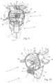
- the working device 1 comprises an actuating lever 4 for operating the drive motor 2 and a locking lever 5 for the actuating lever 4.
- the operating lever 4 and the locking lever 5 are arranged on the housing 26 at the front end 28 of the handle 26.
- a locking position 10 of the locking lever 5 the operating lever 4 is blocked by the locking lever 5.
- the operating lever 4 blocked by the locking lever 5 is in an unactuated position.
- a release position 11, 11' of the locking lever 5 the operating lever 4 is released.
- the operator can move the operating lever 4 into a working position 13 ( Figures 9, 10 ) to operate the drive motor 2.
- the locking lever 5 is pivotably mounted on the housing 23 about its axis of rotation 8 of the locking lever 5.
- the actuating lever 4 is pivotably mounted on the housing 23 about a pivot axis 9.
- the pivot axis 9 is perpendicular to a longitudinal plane 27 ( Fig.3 ) of the handle 26, the longitudinal plane 27 containing the longitudinal axis 18 of the handle 26 and running parallel to the axis of rotation 8 of the locking lever 5.
- the term “parallel” also includes that both the axis of rotation 8 of the locking lever 5 and the longitudinal axis 18 can be contained in the longitudinal plane 27.
- the locking lever 5 comprises a flag 37 with an end face 52, the flag 37 being arranged on the side of the locking lever 5 facing the actuating lever 4.
- the actuating lever 4 comprises a counter flag 38 with a counter end face 53 which is arranged on the side of the actuating lever 4 facing the locking lever 5.
- the end face 52 of the flag 37 and the counter end face 53 of the counter flag 38 are aligned facing each other in the locking position 10. If the actuating lever 4 is pressed, the front surface 52 and the counter-front surface 53 come into contact, whereby pivoting of the actuating lever 4 about the pivot axis 9 is blocked. If the locking lever 5 is moved to a release position 11, 11' ( Figures 7, 8 ), the locking lever 5 releases the actuating lever 4.
- the flag 37 of the locking lever 5 is thereby moved out of the pivoting path of the counter flag 38 of the actuating lever 4.
- the actuating lever 4 can be pivoted with its counter flag 38 about the pivot axis 9 without contacting the flag 37 of the locking lever 5.
- the working device 1 comprises a switch 43 with a contact tongue 44 for actuating the drive motor 2.
- the actuating lever 4 presses in the contact tongue 44, whereby the drive motor 2 is switched on.
- Such a switch 43 would be actuated directly by the actuating lever 4.
- the drive motor 2 can only be switched on or off via the actuating lever 4.
- the speed of the drive motor 2, which is designed as an electric motor is continuously adjustable via the actuating lever 4.
- the longitudinal axis 18 of the handle 26 forms an angle ⁇ with the axis of rotation 8 of the locking lever 5 when viewed perpendicular to the longitudinal plane 27.
- the angle ⁇ is in a range from 10° to 60°, in particular from 15° to 45°. In the exemplary embodiment, the angle ⁇ is in particular approximately 45°. If the operator holds the implement 1 firmly by the handle 26, the operator can actuate the locking lever 5 with his thumb. The operator only has to perform a pivoting movement with his thumb.
- the longitudinal axis 18 is defined by a tangent to a center line of the handle 26 at the front end.
- the center line runs through the center of gravity of the individual cross-sectional planes of the handle 26 that are parallel to one another.
- the locking lever 5 comprises a hub 55, wherein the locking lever 5 is provided with two bearing pins 56 ( Fig.6 ) is pivotally mounted about the rotation axis 8 of the locking lever 5.
- the bearing pins 56 are advantageously formed on the locking lever 5.
- the bearing pins 56 can also be formed by a separate shaft and can be pivotally mounted relative to the housing 23 about the rotation axis 8 of the locking lever 5.
- the locking lever 5 in the embodiment comprises two wall sections 58, 58', which run in the shape of a circular segment.
- the wall sections 58, 58' are connected to the hub 55 via a central web 59.
- the two wall sections 58, 58' are arranged opposite one another in the locking position 10 with respect to the longitudinal plane 27.
- the wall sections 58, 58' are arranged and designed symmetrically to one another.
- the wall sections 58, 58' each extend over an angle ⁇ ( Fig.5 ) about the axis of rotation 8, wherein the angle ⁇ is at least 60°, in particular at least 75°, preferably approximately 90°.
- the wall sections 58, 58' form a peripheral wall 14 of the locking lever 5 with a diameter d.
- the locking lever 5 comprises two lateral wing elements 24, 24' for actuating the locking lever 5.
- the two lateral wing elements 24, 24' are arranged on the wall sections 58, 58'.
- the two lateral wing elements 24, 24' are in particular formed in one piece with the wall sections 58, 58'.
- the lateral wing elements 24, 24' extend approximately perpendicular to the longitudinal plane 27 away from the peripheral wall 14 of the locking lever 5.
- the lateral wing elements 24, 24' protrude from openings 48, 48' provided in the housing 23, whereby the locking lever 5 is accessible to the operator outside the housing 23.
- the openings 48, 48' are arranged opposite the locking lever 5 in such a way that the wall sections 58, 58' cover the interior space enclosed by the housing 23 at the openings 48, 48'.
- the wing elements 24, 24' are arranged opposite one another on the locking lever 5 with respect to the longitudinal plane 27 of the handle 26.
- the wing elements 24, 24' are designed to be symmetrical to one another with respect to the longitudinal plane 27.
- the wing elements 24, 24' each have a width a measured perpendicular to the longitudinal plane 27.
- the width a in the exemplary embodiment corresponds to at least 15%, in particular at least 30%, preferably 38% of the diameter d of the locking lever 5.
- the width a of the wing elements 24, 24' corresponds to a maximum of 50% of the diameter d of the locking lever 5.
- the wing elements 24, 24' have an upper wing side 46 facing away from the actuating element 4 and a lower wing side 47 facing the actuating element 4.
- the lateral wing elements 24, 24' have a height b which corresponds to the distance between the lower wing side 47 and the upper wing side 46 measured in the direction perpendicular to the axis of rotation 8 and parallel to the longitudinal plane 27.
- the height b corresponds to a maximum of 20% of the diameter d of the locking lever 5.
- the lateral wing elements 24, 24' lie in a plane with the axis of rotation 8, wherein the plane is aligned perpendicular to the longitudinal plane 27.
- the working device 1 comprises a spring unit 6.
- the spring unit 6 pretensions the locking lever 5 in the direction of the locking position 10.
- the locking lever 5 has a contour 15 which interacts with the spring unit 6.
- the contour 15 is formed from two legs 17, 17' which are connected to one another in a lower section 16.
- the lower section 16 is the section of the contour 15 closest to the axis of rotation 8 and forms a depression in the contour 15 running towards the axis of rotation 8.
- the individual legs 17, 17' are arc-shaped.
- the legs 17, 17' run from radially outside to inside with respect to the axis of rotation 8 of the locking lever 5.
- the locking lever 5 is designed such that the legs 17, 17' in the locking position 10 run in an arc from the upper ends of the wall sections 58, 58' facing away from the actuating lever 4 to the longitudinal plane 27 and are supported on the hub 55 via a connecting web 35.
- the contour 15 formed by the legs 17, 17' corresponds approximately to the shape of a V.
- the contour 15 is aligned such that the lower section 16 of the contour 15 is arranged towards the axis of rotation 8 of the locking lever 5 and the contour 15 opens in its V-shape away from the axis of rotation 8 of the locking lever 5.
- the longitudinal plane 27 runs centrally through the lower section 16.
- the Tangents 49, 49' adjacent to legs 17 enclose an angle ⁇ , which in the exemplary embodiment lies in a range between 70° and 130°, preferably between 90° and 110°.
- the angle ⁇ corresponds approximately to 100°.
- the spring unit 6 rests against the contour 15 of the locking lever 5.
- the spring unit 6 acts with a spring force F F ( Fig.5 ) on the contour 15 in the direction of the axis of rotation 8 of the locking lever 5.
- the preload force vector which corresponds to the vector of the spring force F F , lies in the longitudinal plane 27.
- the contour 15 can also be designed such that the contour 15 opens in its V-shape downwards towards the axis of rotation 8.
- the spring unit 6 would be arranged between the axis of rotation 8 and the contour 15 and would act on the contour 15 away from the axis of rotation 8.
- the spring unit 6 is designed as a leaf spring.
- the spring unit 6 can also be designed as a leg spring or the like. The spring unit 6 is designed symmetrically with respect to the longitudinal plane 27.
- the locking lever 5 comprises a first pivoting direction 19 and a second pivoting direction 19' opposite to the first pivoting direction 19. If the locking lever 5, as shown in the Figures 7 to 10 shown, pivoted in one of the two pivot directions 19, 19' around the rotation axis 8 of the locking lever 5, the spring unit 6 is pressed by the contour 15 of the locking lever 5 in the direction away from the rotation axis 8 of the locking lever 5. The spring unit 6 slides along one of the two legs 17, 17' of the contour 15, whereby the spring force F F acting on the contour 15 of the locking lever 5 increases. At the contact point between the spring unit 6 and the contour 15, a restoring force F R resulting from the spring force F F acts approximately normal to the surface on the contour 15.
- the restoring force F R causes a restoring moment M R which counteracts the pivot direction, in the embodiment of the first pivot direction 19. If the locking lever 5 is released by the operator, no actuating force acts on the locking lever 5. Only the spring force F F acts through the Spring unit 6 on the locking lever 5. The restoring force F R resulting from the spring force F F causes the restoring torque M F , whereby the locking lever 5 is rotated back into the locking position 10.
- the spring unit 6 and the contour 15 generate an approximately constant restoring torque M R over the entire pivoting path of the locking lever.
- the resulting spring force F R increases.
- the contour 15, on the other hand flattens out with increasing radial distance from the axis of rotation 8 of the locking lever 5 such that the direction of the restoring force F R is directed closer to the axis of rotation 8 of the locking lever 5. Consequently, the lever arm of the restoring force F R to the axis of rotation 8 of the locking lever 5 also decreases, as a result of which the restoring torque M R remains approximately constant.
- the contour 15 is preferably designed such that when the locking lever 5 is pivoted over the entire pivoting range, an approximately constant restoring torque M R acts.
- the contour 15 can be designed in an alternative embodiment according to the desired restoring torque M R. Due to the symmetrical design of the legs 17, 17' of the contour 15, the restoring force FR is also of the same magnitude for the same deflection in the respective pivoting direction 19, 19'. This results in a particularly pleasant pivoting behavior for the operator in all pivoting directions 19, 19' of the locking lever 5.
- the pivoting behavior of the locking lever 5 is the same, regardless of which of the two lateral wing elements 24, 24' is actuated and in which pivoting direction 19, 19' one of the two lateral wing elements 24, 24' is pressed.
- the spring unit 6 in the embodiment comprises two opposing spring legs 30 and 31, which are formed at the end of the spring unit 6 adjacent to the contour 15.
- the spring legs 30, 31 run in the direction away from the contour 15.
- the spring legs 30, 31 are formed in the preferred embodiment as bent sections of the spring unit 6, whereby the spring unit 6 has a rounded contact surface with respect to the contour 15. This facilitates the sliding up and down of the spring unit 6 on the contour 15.
- the spring unit 6 has a width g measured perpendicular to the longitudinal plane 27, which corresponds to at least 20% of the diameter d of the locking lever 5. Due to the wide design of the spring unit 6, the spring unit 6 rests in the locking position 10 of the locking lever 5 at two contact points on the contour 15, namely on one of the two legs 17, 17' of the contour 15 ( Fig.4 ). The spring unit 6, which is pre-tensioned in the direction of the axis of rotation 8 of the locking lever 5, thus exerts a restoring force F R on both legs 17, 17' of the contour 15. These restoring forces F R in turn cause opposing restoring moments M R .
- the spring unit 6 acts with the spring force F F on the locking lever 5 in the direction of the axis of rotation 8 of the locking lever 5. Due to the wide design of the spring unit 6, however, the force is introduced at the contour 15 not in the direction of the axis of rotation 8 of the locking lever 5, but offset from it. As a result, large restoring moments M R can be generated even with small deflections of the locking lever 5.
- a lower edge 36, 36' of the openings 48, 48' of the housing 23 serves as a rotation stop of the locking lever 5.
- the lower edge 36, 36' is the edge of the openings 48, 48' of the housing 23 that is closest to the actuating lever 4. If the locking lever 5 is arranged in the release position 11, 11', the lower edge 36, 36' of the opening 48, 48' forms a stop for the wing element 24, 24'. Accordingly, the locking lever 5 can be rotated in the first pivoting direction 19 until the lateral wing element 24 with its wing top 46 against the lower edge 36 of the opening 48 In an alternative embodiment, it may also be appropriate to provide the upper edges of the openings 48, 48' as a stop for the wing elements 24, 24'.
- the locking lever 5 is shown pivoted into the release position 11, and the actuating lever 4 is actuated and is in the working position 13.
- the flag 37 of the locking lever 5 and the counter flag 38 of the actuating lever 4 do not contact each other.
- the working device 1 comprises a spring element 7, which pre-tensions the actuating lever 4 in the direction of the unactuated position 12.
- the spring element 7 is designed as a leg spring in the exemplary embodiment.
- the spring element 7 is designed symmetrically with respect to the longitudinal plane 27 in order to avoid undesirable tilting moments on the actuating lever 4.
- the spring element 7 comprises two spring legs 21, 21', which are clamped to one component of the housing 23 and the actuating lever 4, the spring element 7 being supported by a central spring section 25 on the other component of the housing 23 and the actuating lever 4.
- the central spring section 25 of the spring element 7 is on the housing 23 ( Fig.6 ).
- the spring legs 21, 21' of the spring element 7 are clamped at their ends 22, 22' on the actuating lever 4.
- the spring legs 21, 21' are additionally supported between their ends and the pivot axis 9 on the actuating lever 4.
- the windings of the spring element 7 are supported on a bearing pin 73 of the actuating lever 4, on which the actuating lever 4 is pivotally mounted. If no actuating force acts on the actuating lever 4, it is tensioned into the unactuated position by the spring element 7. In order to press the actuating lever 4 into the working position 13, the spring force of the spring element 7 must be overcome.
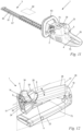
- FIG. 11 an embodiment of a working device 1 according to the invention is shown, namely a hedge trimmer.
- the same reference numerals as in the embodiment after the Figures 1 to 10 denote corresponding components.
- the working device 1 has, as a tool 3, a blade bar 60 with two reciprocating cutting blades 61, 61', which determine a cutting plane 62.
- a drive unit with the schematically shown drive motor 2 is accommodated in the housing 23, which is fed via the battery 39 plugged into the housing 23.
- the hedge trimmer is an electric hedge trimmer, in particular a battery-operated hedge trimmer.
- the housing 23 has the handle 26, which is designed as a rear handle in the longitudinal direction of the working device 1.
- the locking lever 5 arranged on the housing 23 is only shown schematically in the form of a dashed rectangle.
- the actuating lever 4 is arranged on the housing 23.
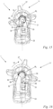
- Fig. 12 is a detail of the part of the housing 23 of the working device 1 according to the invention
- Fig. 11 which comprises the handle 26 and on which the locking lever 5 and the actuating lever 4 are arranged.
- the handle 26 merges at its rear end 29, i.e. the end of the handle 26 facing away from the locking lever 5, into a base body 73 of the housing 23.
- the working device 1 comprises a hand stop 50, via which the handle 26 merges at its front end 28 into the base body 73 of the housing 23.
- the hand stop 50 is formed on the housing 23 at the front end 28 of the handle 26 and extends away from the handle 26 in the direction from the actuating lever 4 to the handle 26.
- the hand stop 50 forms a stop for the operator's hand towards the front in the direction of the longitudinal axis 18 of the handle 26.
- the hand stop 50 is used to support the operator's thumb saddle.
- the locking lever 5 is arranged adjacent to the hand stop 50.
- the longitudinal axis 18 of the handle 26 and the rotation axis 8 of the locking lever 5 enclose the angle ⁇ , which opens away from the base body 73 of the housing 23.
- the angle ⁇ is in a range from 10° to 60°, preferably from 15° to 45°.
- angle ⁇ is approximately 15° in the direction perpendicular to the longitudinal plane 27.
- the locking lever 5 differs from the locking lever 5 according to the embodiment according to Fig.1 essentially in that the locking lever 5 has three wing elements 24, 24', 34 ( Fig. 14 ).
- the tool according to the invention with such a locking lever 5 with three wing elements 24, 24', 34 can also be designed in an alternative embodiment, for example as a chainsaw, blower or the like.
- the tool 1 can also be designed as a tool with a shaft, for example as a pole pruner, hedge trimmer, brush cutter, lawn trimmer, brush cutter or the like. Between the lateral wing elements 24, 24' there is a further, upper wing element 34 on the locking lever 5.
- the wing elements 24, 24', 34 comprise an upper wing element 34 and two lateral wing elements 24, 24' in the direction of the longitudinal axis 18.
- the upper wing element 34 lies in the circumferential direction between the two lateral wing elements 24, 24'.
- the upper wing element 34 of the three wing elements 24, 24', 34 is arranged on the locking lever 5 opposite the actuating lever 4 with respect to the axis of rotation 8 of the locking lever 5.
- the two lateral wing elements 24, 24' of the three wing elements 24, 24', 34 of the locking lever 5 are arranged opposite one another on the locking lever 5 with respect to the longitudinal plane 27, in particular mirror-symmetrically.
- the two lateral wing elements 24, 24' of the locking lever 5 have an equal angular distance ⁇ around the axis of rotation 8 of the locking lever 5 to the upper wing element 34.
- the angular distance ⁇ in the exemplary embodiment is at least 60°, in particular at least 70°, preferably approximately 90°.
- the wing elements 24, 24', 34 are formed on the peripheral wall 14 of the locking lever 5. Accordingly, the wing elements 24, 24', 34 on the locking lever 5 are formed in one piece.
- the housing 23 has a groove 51 which extends at least 180° around the axis of rotation 8 of the locking lever 5.
- the locking lever 5 is arranged in the groove 51, with the wing elements 24, 24', 34 protruding from the groove 51 and thus being easily accessible to the operator from outside the housing 23.
- the locking lever 5 has only one wall section 58, which is connected to a shaft 70 of the locking lever 5 via the central web 59 and the connecting web 35. All three wing elements 24, 24', 34 are formed on the wall section 58.
- the embodiment shown here for a working device 1 comprises a compared to the embodiment according to Fig.1 Alternative design of a spring unit 6.
- the spring unit 6 preloads the locking lever 5 in the direction of the locking position 10.
- the spring unit 6 is designed as a leaf spring, but in an alternative embodiment it can also be designed as a leg spring or the like or can comprise several springs.
- the spring unit 6 comprises a first spring leg 30 and a second spring leg 31.
- the spring legs 30, 31 are connected via an arcuate section 72 of the spring unit 6. Accordingly, the spring unit 6 has approximately a V-shape.
- the spring unit 6 is designed in one piece. The spring unit 6 is clamped to the locking lever 5.
- the spring legs 30, 31 protrude from the peripheral wall of the locking lever 5 and are directed towards the actuating lever 4 in the locking position.
- the curved section 72 of the spring unit 6 extends around part of the circumference of the shaft 70 of the locking lever 5.
- the spring unit 6 is also clamped to the locking lever 5 via three guides 54. Two of the three guides 54 are formed opposite one another on the central web 59 with respect to the longitudinal plane 27.
- the other guide 54 is formed on the connecting web 35 of the locking lever 5.
- the guides 54 are each formed as a slot, in particular as an opening.
- the spring unit is clamped in a pre-tensioned manner in the guides 54, in particular in the guides 54 provided on the central web 59.
- the housing 23 forms a first rotation stop 32 and a second rotation stop 33.
- a first stop surface 68 and a second stop surface 69 are formed on the locking lever 5.
- the stop surfaces 68, 69 are formed at the ends of the wall section 58.
- the spring unit 6 is arranged opposite the housing 23 in such a way that when the locking lever 5 is pivoted in the first pivoting direction 19, the first spring leg 30 of the spring unit 6 is deflected by the first stop surface 68 of the locking lever 5 in the direction of the longitudinal plane 27.
- the spring unit 6 is supported by the second spring leg 31 on the second rotation stop 33 of the housing 23 ( Fig. 15 ).
- the spring unit 6 acts on the stop surface 68 of the locking lever 5 with a spring force.
- the second spring leg 31 lies approximately flat against the stop surface 68, whereby the spring force corresponds approximately to the restoring force F R acting on the locking lever.
- the restoring force F R in turn generates the restoring moment M R , by means of which the locking lever 5 is pivoted from the release position 11 back into the locking position 10. If the locking lever 5 is deflected in the second pivoting direction 19', the second spring leg 31 is deflected via the second stop surface 69 of the locking lever 5 in the direction of the longitudinal plane 27.
- the spring unit 6 is supported via the first spring leg 30 on the first rotation stop 32 of the housing 23 ( Fig. 16 ).
- the formation of the effective forces is analogous to the first spring leg 30.
- the restoring force F R is equal in magnitude in both pivot directions 19, 19' with the same deflection.
- the spring unit 6 is designed symmetrically to the longitudinal plane 27.
- the locking lever 5 is also designed symmetrically to the longitudinal plane 27. This creates In both different pivoting directions 19, 19', equal-magnitude restoring forces F R and equal-magnitude restoring moments M R are generated.
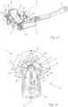
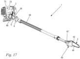
- a pole pruner is shown in Fig. 17 as an alternative embodiment of a working device 1 according to the invention.
- the working device 1 comprises the drive unit, which is connected to a cutting head 65 via a shaft, which comprises a guide tube 64.
- the shaft or the guide tube 64 form part of the housing 23.
- the drive unit is arranged in the housing 23 and comprises the schematically shown drive motor 2.
- the drive motor 2 is designed as an internal combustion engine in the exemplary embodiment.
- the drive motor 2 is an electric motor.
- the drive motor 2 is arranged on the cutting head 65, in particular if the drive motor 2 is an electric motor.
- a battery 39 for supplying the drive motor 2 with energy can then be provided in the housing 23, for example.
- the guide tube 64 is designed as a telescopic tube in the exemplary embodiment.
- the guide tube 64 has a first end 66 to which the drive unit is attached.
- the handle 26 is fixed to the guide tube 64 adjacent to the first end 66 of the guide tube 64.
- the actuating lever 4 and the schematically illustrated locking lever 5 are mounted on the handle 26.
- the cutting head 65 is arranged at a second end 67 of the guide tube 64.
- a drive shaft can protrude through the guide tube 64 if the drive motor 2 is arranged in the base body 73 of the housing 23. If the drive motor 2 is arranged on the cutting head 65, energy and signal lines advantageously run through the guide tube 64.
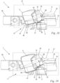
- the guide tube 64, the handle 26 as well as the operating lever 4 and the locking lever 5 are shown.
- the longitudinal axis 18 of the handle 26 and the rotation axis 8 of the locking lever 5 enclose the angle ⁇ when viewed perpendicularly to the longitudinal plane 27.
- the angle ⁇ lies in a range between 10° and 60°, preferably between 15° and 45°. In the exemplary embodiment, the angle ⁇ is in particular approximately 15°.
- the locking lever 5 has a shaft 70 which is pivotably mounted in the housing 23 about the axis of rotation 8 of the locking lever 5.
- the wall section 58 is connected to the shaft 70 via the connecting web 35.
- the connecting web 35 lies in the locking position 10 of the locking lever 5 in the longitudinal plane 27.
- the shaft 70 and the locking lever 5 are formed in one piece.
- the shaft 70 comprises an extension on which the flag 37 is formed.
- the actuating lever 4 is blocked in its pivoting direction for actuating the drive motor 2 by the flag 37 of the shaft 70. When the actuating lever 4 is actuated, the front surface 52 of the flag 37 and the counter-front surface 53 of the counter flag 38 come into contact.
- the actuating lever 4 is locked.
- the locking lever 5 is in the locking position 10.
- the locking lever 5 is pivoted in the second pivoting direction 19', so that the flag 37 releases the counter flag 38.
- the actuating lever 4 can be actuated, i.e. pressed in the direction of the rotation axis 8 of the locking lever 5, without the flag 37 and the counter flag 38 coming into contact.
- the locking lever 5 is in the second release position 11'.
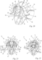
- the three wing elements 24, 24', 34 are formed on the locking lever 5.
- the locking lever 5 differs from the one shown in Fig. 12 shown locking lever 5 in that in the locking position 10 both the maximum distance e and the minimum distance f between the lateral wing elements 24, 24' and the axis of rotation 8 of the locking lever 5 are larger.
- the maximum distance e corresponds to at least 15%, preferably at least 25%, in particular approximately 30% of the diameter d of the locking lever 5.
- the minimum distance f corresponds to at least 5%, in particular at least 10% of the diameter d of the locking lever 5.
- the wall section 58 extends over the angle ⁇ ( Fig. 22 ) about the axis of rotation 8 of the locking lever 5, wherein the angle ⁇ is at least 180°, in particular at least 200°, preferably approximately 250°.
- Such tools 1 with a shaft are used for cutting trees or high hedges.
- the operator holds the tool 1 in such a way that the shaft points upwards. This means that the handle 26 must be held in an angled position.
- the thumb is a large distance from the axis of rotation 8 of the locking lever 5 in the direction of the actuating lever 4. Due to the low arrangement of the lateral wing elements 24, 24' on the locking lever 5, the distances e, f of the lateral wing elements 24, 24' from the axis of rotation of the locking lever 5 are significantly increased. This results in a relaxed grip position for the operator, especially with an angled hand position.
- the spring unit 6 is shown, which is in its installation position compared to the spring unit of the embodiment according to Fig. 12
- the spring unit 6 also has a first spring leg 30 and a second spring leg 31, which are connected to one another via an arcuate section 72.
- the spring unit 6 has an approximately V-shape. However, the spring unit 6 is installed rotated by 180° with respect to the axis of rotation 8 of the locking lever 5.
- the spring legs 30, 31 run away from the actuating lever 4 in the direction of the upper wing element 34.
- the spring unit 6 is clamped between the shaft 70 of the locking lever 5 and a shaft holder 57 provided for the locking lever 5.
- the spring legs 30, 31 extend approximately to the inside of the locking lever 5.
- the stop surfaces 68, 69 for supporting the spring legs 30, 31 are formed on the inside of the locking lever 5.
- the first rotation stop 32 and the second rotation stop 33 are formed by the housing 23, in particular by the base body of the housing 23 or by recesses in the guide tube 64.
- the housing 23 extends via two webs 71, 71' into the interior of the locking lever 5.
- the webs 71, 71' are formed opposite one another with respect to the longitudinal plane 27.
- the two webs 71, 71' extend approximately to the two stop surfaces 68, 69, but without contacting them.
- the rotation stops 32, 33 are formed at the ends of the webs 71, 71'. In an alternative embodiment according to the invention, the rotation stops 32, 33 are formed either by the base body of the housing 23 or by the guide tube 64.
- the first rotation stop 32 blocks the rotational movement of the first spring leg 30 in the second pivoting direction 19'.
- the spring unit 6 thereby exerts a restoring force F R on the locking lever 5 via its second spring leg 31, which preloads the locking lever 5 back into its locking position 10.
- the first spring leg 30 is supported on the first rotation stop 32, with the second spring leg 32 acting on the locking lever 5 via the first stop surface 68 of the locking lever 5.
- the second rotation stop 33 limits a rotational movement of the second spring leg 31 in the first pivoting direction 19.
- the second spring leg 31 is deflected accordingly at the second rotation stop 33.
- the first spring leg 30 causes a restoring force F R which prestresses the locking lever 5 via the second stop surface 69 against the first pivot direction 19 back into the locking position 10, wherein the first spring leg 30 is supported on the first rotation stop 32.
- the spring legs 30, 31 are clamped on the stop surfaces 68, 69 formed on the inside of the locking lever 5.
- the spring unit 6 is prestressed in the locking position 10, in particular clamped between the shaft 70 and the shaft holder 57 and between the two stop surfaces 68, 69.
Claims (9)
- Appareil de travail à main, comprenant un outil (3) et un moteur d'entraînement (2) destiné à l'entraînement de l'outil (3), une poignée (26), la poignée (26) présentant un axe longitudinal (18), un levier d'actionnement (4) destiné à commander le moteur d'entraînement (2), un levier de blocage (5) destiné au levier d'actionnement (4), le levier de blocage (5) étant monté de manière pivotante sur un axe de rotation (8) du levier de blocage (5), et un plan longitudinal (27), le plan longitudinal (27) contenant l'axe longitudinal (18) de la poignée (26) et s'étendant parallèlement à l'axe de rotation (8) du levier de blocage (5), le levier de blocage (5) bloquant le levier d'actionnement (4) dans une position de blocage (10) et le libérant dans au moins une position de libération (11, 11') pour effectuer l'actionnement,
caractérisé en ce que le levier de blocage (5) comporte trois éléments formant ailette (24, 24', 34) pour actionner le levier de blocage (5). - Appareil de travail à main selon la revendication 1,
caractérisé en ce qu'un élément formant ailette parmi les trois éléments formant ailettes (24, 24', 34) est un élément formant ailette supérieur (34), l'élément formant ailette supérieur (34) étant disposé sur le levier de blocage (5) à l'opposé du levier d'actionnement (4) par rapport à l'axe de rotation (8) du levier de blocage (5). - Appareil de travail à main selon la revendication 2,
caractérisé en ce que deux des trois éléments formant ailette (24, 24', 34) sont des éléments formant ailette latéraux (24, 24'), les deux éléments formant ailette latéraux (24, 24') du levier de blocage (5) étant disposés l'un en face de l'autre sur le levier de blocage (5) par rapport au plan longitudinal (18) de la poignée (26). - Appareil de travail à main selon la revendication 3,
caractérisé en ce que les deux éléments formant ailette latéraux (24, 24') du levier de blocage (5) présentent un même espacement angulaire (γ) autour de l'axe de rotation (8) du levier de blocage (5) par rapport à l'élément formant ailette supérieur (34), l'espacement angulaire (γ) étant d'au moins 60°. - Appareil de travail à main selon l'une des revendications 1 à 4,
caractérisé en ce que l'axe longitudinal (18) de la poignée (26) forme un angle (α) avec l'axe de rotation (8) du levier de blocage (5) dans la direction perpendiculaire au plan longitudinal (27), l'angle (α) étant compris entre 10° et 60°. - Appareil de travail à main selon la revendication 5,
caractérisé en ce que l'angle (α) est compris entre 15° et 45°. - Appareil de travail à main selon l'une des revendications 1 à 6,
caractérisé en ce que deux positions de libération (11, 11') sont prévues et en ce que le levier de blocage (5) peut pivoter depuis sa position de blocage (10), dans un premier sens de pivotement (19) sur l'axe de rotation (8) du levier de blocage (5) jusque dans la première position de libération (11) et, dans un deuxième sens de pivotement (19') opposé au premier sens de pivotement (19), jusque dans la deuxième position de libération (11'). - Appareil de travail à main selon la revendication 7,
caractérisé en ce que, lorsque le levier de blocage (5) est dévié angulairement de la position de blocage (10), une unité à ressort (6) provoque une force de rappel dont l'intensité en valeur absolue est la même dans le premier sens de pivotement (19) et dans le deuxième sens de pivotement (19') pour une même déviation angulaire. - Appareil de travail à main selon l'une des revendications 1 à 8,
caractérisé en ce que les éléments formant ailette (24, 24') en position de blocage (10) sont accessibles aussi bien du côté situé dans le premier sens de pivotement (19) que du côté situé dans le deuxième sens de pivotement (19').
Priority Applications (1)
| Application Number | Priority Date | Filing Date | Title |
|---|---|---|---|
| EP20197561.2A EP3792009B1 (fr) | 2019-09-12 | 2019-09-12 | Appareil de travail portatif doté d'un outil |
Applications Claiming Priority (2)
| Application Number | Priority Date | Filing Date | Title |
|---|---|---|---|
| EP19197112.6A EP3792006A1 (fr) | 2019-09-12 | 2019-09-12 | Appareil de travail portatif doté d'un outil |
| EP20197561.2A EP3792009B1 (fr) | 2019-09-12 | 2019-09-12 | Appareil de travail portatif doté d'un outil |
Related Parent Applications (2)
| Application Number | Title | Priority Date | Filing Date |
|---|---|---|---|
| EP19197112.6A Division EP3792006A1 (fr) | 2019-09-12 | 2019-09-12 | Appareil de travail portatif doté d'un outil |
| EP19197112.6A Division-Into EP3792006A1 (fr) | 2019-09-12 | 2019-09-12 | Appareil de travail portatif doté d'un outil |
Publications (2)
| Publication Number | Publication Date |
|---|---|
| EP3792009A1 EP3792009A1 (fr) | 2021-03-17 |
| EP3792009B1 true EP3792009B1 (fr) | 2024-04-24 |
Family
ID=67953708
Family Applications (3)
| Application Number | Title | Priority Date | Filing Date |
|---|---|---|---|
| EP19197112.6A Pending EP3792006A1 (fr) | 2019-09-12 | 2019-09-12 | Appareil de travail portatif doté d'un outil |
| EP20197561.2A Active EP3792009B1 (fr) | 2019-09-12 | 2019-09-12 | Appareil de travail portatif doté d'un outil |
| EP20197560.4A Active EP3792008B1 (fr) | 2019-09-12 | 2019-09-12 | Appareil de travail portatif doté d'un outil |
Family Applications Before (1)
| Application Number | Title | Priority Date | Filing Date |
|---|---|---|---|
| EP19197112.6A Pending EP3792006A1 (fr) | 2019-09-12 | 2019-09-12 | Appareil de travail portatif doté d'un outil |
Family Applications After (1)
| Application Number | Title | Priority Date | Filing Date |
|---|---|---|---|
| EP20197560.4A Active EP3792008B1 (fr) | 2019-09-12 | 2019-09-12 | Appareil de travail portatif doté d'un outil |
Country Status (3)
| Country | Link |
|---|---|
| US (1) | US11958155B2 (fr) |
| EP (3) | EP3792006A1 (fr) |
| CN (1) | CN112470737A (fr) |
Families Citing this family (10)
| Publication number | Priority date | Publication date | Assignee | Title |
|---|---|---|---|---|
| USD932268S1 (en) * | 2020-11-04 | 2021-10-05 | Shenghui Liao | Pruning saw |
| USD926007S1 (en) * | 2020-12-29 | 2021-07-27 | Yongkang Huiyan Industry and Trade Co., Ltd. | Chainsaw |
| US20220288765A1 (en) * | 2021-03-15 | 2022-09-15 | Andreas Stihl Ag & Co. Kg | Hand- guided work apparatus |
| USD959945S1 (en) * | 2021-06-22 | 2022-08-09 | Jimin Lin | Mini chainsaw |
| USD957225S1 (en) * | 2021-07-04 | 2022-07-12 | Hefei Qiongzhi Network Technology Co., Ltd. | Mini chainsaw |
| USD1020421S1 (en) * | 2021-08-25 | 2024-04-02 | Jinhua Bochao Tools Co., Ltd | Lithium battery-powered chainsaw |
| WO2024051895A1 (fr) | 2022-09-09 | 2024-03-14 | Andreas Stihl Ag & Co. Kg | Scie de jardin |
| DE102022123061A1 (de) | 2022-09-09 | 2024-03-14 | Andreas Stihl Ag & Co. Kg | Gehölzschneider |
| DE102022123203A1 (de) | 2022-09-12 | 2024-03-14 | Andreas Stihl Ag & Co. Kg | Handgeführtes Arbeitsgerät |
| USD1005075S1 (en) * | 2023-03-29 | 2023-11-21 | Jinyun Mailin Tools Co., Ltd | Chainsaw |
Citations (1)
| Publication number | Priority date | Publication date | Assignee | Title |
|---|---|---|---|---|
| EP2202035B1 (fr) * | 2008-12-26 | 2013-07-24 | Omron Corporation | Outil électrique |
Family Cites Families (21)
| Publication number | Priority date | Publication date | Assignee | Title |
|---|---|---|---|---|
| DE3033604A1 (de) * | 1980-09-06 | 1982-04-22 | Fa. Andreas Stihl, 7050 Waiblingen | Motorsaege |
| DE4102482A1 (de) * | 1991-01-29 | 1992-07-30 | Bosch Gmbh Robert | Handwerkzeugmaschine |
| DE4411002A1 (de) * | 1994-03-30 | 1995-10-05 | Bosch Gmbh Robert | Gerät zum Schneiden von Pflanzen |
| US6091035A (en) | 1998-08-14 | 2000-07-18 | Black & Decker, Inc. | Lockout mechanism for power tool |
| US5988241A (en) * | 1998-11-16 | 1999-11-23 | Porter-Cable Corporation | Ergonomic router handles |
| EP1759813A3 (fr) * | 2002-01-10 | 2008-04-23 | Black & Decker, Inc. | Meuleuse d'angle |
| DE10323544B4 (de) | 2003-05-24 | 2005-10-27 | Preh Gmbh | Rasteinrichtung für ein dreheinstellbares, elektrisches Bauelement |
| DE10353013A1 (de) * | 2003-11-13 | 2005-06-16 | Robert Bosch Gmbh | Handwerkzeugmaschine |
| US7708085B2 (en) * | 2005-11-04 | 2010-05-04 | Robert Bosch Gmbh | Articulating drill with optical speed control and method of operation |
| US7538503B2 (en) * | 2006-04-21 | 2009-05-26 | Andreas Stihl Ag & Co. Kg | Hand-held power tool, in particular a trimmer or the like, having an electric drive motor |
| JP2007299602A (ja) | 2006-04-28 | 2007-11-15 | Tokai Rika Co Ltd | ロータリースイッチ装置 |
| DE102006047451B4 (de) * | 2006-10-07 | 2021-11-04 | Andreas Stihl Ag & Co. Kg | Handgeführtes Arbeitsgerät |
| DE102010054653B4 (de) * | 2010-12-15 | 2022-03-03 | Andreas Stihl Ag & Co. Kg | Handgeführte Heckenschere |
| US8723060B2 (en) * | 2011-12-21 | 2014-05-13 | Robert Bosch Tool Corporation | Method and mechanism for power tool lock-off |
| ES2564015T3 (es) * | 2011-12-22 | 2016-03-17 | Black & Decker Inc. | Dispositivo de corte de vegetación |
| DE102011089722A1 (de) | 2011-12-23 | 2013-06-27 | Robert Bosch Gmbh | Werkzeugmaschine |
| CN104012242B (zh) * | 2013-02-28 | 2018-02-13 | 安德烈亚斯.斯蒂尔两合公司 | 手持式工作器械 |
| DE102013009891A1 (de) * | 2013-06-13 | 2014-12-18 | Andreas Stihl Ag & Co. Kg | Arbeitsgerät mit einem Verbrennungsmotor |
| US10014128B2 (en) * | 2013-12-17 | 2018-07-03 | Robert Bosch Tool Corporation | Portable power tool with trigger switch, trigger release and lock-on mechanism combination |
| DE102014009144A1 (de) * | 2014-06-20 | 2015-12-24 | Andreas Stihl Ag & Co. Kg | Handgeführtes Arbeitsgerät |
| CN206471261U (zh) | 2017-01-16 | 2017-09-05 | 德利威电子股份有限公司 | 可复位的旋钮开关 |
-
2019
- 2019-09-12 EP EP19197112.6A patent/EP3792006A1/fr active Pending
- 2019-09-12 EP EP20197561.2A patent/EP3792009B1/fr active Active
- 2019-09-12 EP EP20197560.4A patent/EP3792008B1/fr active Active
-
2020
- 2020-09-11 CN CN202010953953.5A patent/CN112470737A/zh active Pending
- 2020-09-14 US US17/020,482 patent/US11958155B2/en active Active
Patent Citations (1)
| Publication number | Priority date | Publication date | Assignee | Title |
|---|---|---|---|---|
| EP2202035B1 (fr) * | 2008-12-26 | 2013-07-24 | Omron Corporation | Outil électrique |
Also Published As
| Publication number | Publication date |
|---|---|
| EP3792009A1 (fr) | 2021-03-17 |
| EP3792008A1 (fr) | 2021-03-17 |
| US20210078123A1 (en) | 2021-03-18 |
| CN112470737A (zh) | 2021-03-12 |
| EP3792008B1 (fr) | 2024-05-01 |
| US11958155B2 (en) | 2024-04-16 |
| EP3792006A1 (fr) | 2021-03-17 |
Similar Documents
| Publication | Publication Date | Title |
|---|---|---|
| EP3792009B1 (fr) | Appareil de travail portatif doté d'un outil | |
| DE602004002328T2 (de) | Vegetationsästungsvorrichtung | |
| DE19637874B4 (de) | Heckenschneider mit Motorantrieb | |
| DE19745306C2 (de) | Handgriffanordnung für einen Winkelschleifer | |
| DE60005718T2 (de) | Griff für Mähgerät | |
| EP0102954A1 (fr) | Outil ou jeu d'outils. | |
| DE2816485C2 (de) | Handgriffausbildung an einem tragbaren kraftbetriebenen Werkzeug, insbesondere Motorsäge, Heckenschere od. dgl. | |
| WO2000041554A1 (fr) | Lame pour debroussailleuse | |
| DE19821375B4 (de) | Handhabbare motorangetriebene Arbeitsmaschine | |
| EP1782682A2 (fr) | Appareil de travail guidé manuellement | |
| DE10003984A1 (de) | Arbeitsgerät mit einem Antriebsmotor | |
| DE10332918A1 (de) | Fadenschneider | |
| DE102007008355B4 (de) | Rohrtrennvorrichtung | |
| DE602004002438T2 (de) | Abriegelungsmechanismus für eine schwenkbare Griffanordnung eines Kraftwerkzeugs | |
| DE602004000897T2 (de) | Betätigungsmechanismus für ein Kraftwerkzeug | |
| EP3760025A1 (fr) | Dispositif de commande à poignée et appareil de travail entraîné par un moteur | |
| EP0434781B1 (fr) | Ciseaux manuels a pelouse commandes par moteur electrique | |
| EP1466690A1 (fr) | Scie sauteuse en forme de sabre avec dispositif d'ajustage pour un guide | |
| DE19926375A1 (de) | Motorbetriebenes Gartenwerkzeug, insbesondere Heckenschere | |
| DE602004001941T2 (de) | Griffanordnung für ein Kraftwerkzeug | |
| EP3892082A1 (fr) | Poignée pour un appareil de travail guidé à la main et débroussailleuse | |
| EP0618050B1 (fr) | Rabot à main | |
| DE3633655A1 (de) | Tragbare kreissaege | |
| WO2008110266A2 (fr) | Ciseaux à pelouse comportant un dispositif de préhension | |
| EP0826299B1 (fr) | Taille-haie |
Legal Events
| Date | Code | Title | Description |
|---|---|---|---|
| PUAI | Public reference made under article 153(3) epc to a published international application that has entered the european phase |
Free format text: ORIGINAL CODE: 0009012 |
|
| STAA | Information on the status of an ep patent application or granted ep patent |
Free format text: STATUS: THE APPLICATION HAS BEEN PUBLISHED |
|
| AC | Divisional application: reference to earlier application |
Ref document number: 3792006 Country of ref document: EP Kind code of ref document: P |
|
| AK | Designated contracting states |
Kind code of ref document: A1 Designated state(s): AL AT BE BG CH CY CZ DE DK EE ES FI FR GB GR HR HU IE IS IT LI LT LU LV MC MK MT NL NO PL PT RO RS SE SI SK SM TR |
|
| AX | Request for extension of the european patent |
Extension state: BA ME |
|
| RIN1 | Information on inventor provided before grant (corrected) |
Inventor name: MANN, VERENA Inventor name: MANDEL, ROLAND Inventor name: MAIER, THOMAS Inventor name: KERN, FRANZISKA Inventor name: OBERHOFER, FELIX Inventor name: JENKE, MARCUS Inventor name: POSNER, BENEDIKT Inventor name: BATHKE, LARS |
|
| STAA | Information on the status of an ep patent application or granted ep patent |
Free format text: STATUS: REQUEST FOR EXAMINATION WAS MADE |
|
| 17P | Request for examination filed |
Effective date: 20210907 |
|
| RBV | Designated contracting states (corrected) |
Designated state(s): AL AT BE BG CH CY CZ DE DK EE ES FI FR GB GR HR HU IE IS IT LI LT LU LV MC MK MT NL NO PL PT RO RS SE SI SK SM TR |
|
| GRAP | Despatch of communication of intention to grant a patent |
Free format text: ORIGINAL CODE: EPIDOSNIGR1 |
|
| STAA | Information on the status of an ep patent application or granted ep patent |
Free format text: STATUS: GRANT OF PATENT IS INTENDED |
|
| INTG | Intention to grant announced |
Effective date: 20231122 |
|
| RIN1 | Information on inventor provided before grant (corrected) |
Inventor name: POSNER, BENEDIKT Inventor name: MANDEL, ROLAND Inventor name: BATHKE, LARS Inventor name: MANN, VERENA Inventor name: MAIER, THOMAS Inventor name: KERN, FRANZISKA Inventor name: JENKE, MARCUS Inventor name: OBERHOFER, FELIX |
|
| GRAS | Grant fee paid |
Free format text: ORIGINAL CODE: EPIDOSNIGR3 |
|
| GRAA | (expected) grant |
Free format text: ORIGINAL CODE: 0009210 |
|
| STAA | Information on the status of an ep patent application or granted ep patent |
Free format text: STATUS: THE PATENT HAS BEEN GRANTED |
|
| AC | Divisional application: reference to earlier application |
Ref document number: 3792006 Country of ref document: EP Kind code of ref document: P |
|
| AK | Designated contracting states |
Kind code of ref document: B1 Designated state(s): AL AT BE BG CH CY CZ DE DK EE ES FI FR GB GR HR HU IE IS IT LI LT LU LV MC MK MT NL NO PL PT RO RS SE SI SK SM TR |
|
| REG | Reference to a national code |
Ref country code: GB Ref legal event code: FG4D Free format text: NOT ENGLISH |
|
| REG | Reference to a national code |
Ref country code: CH Ref legal event code: EP |
|
| REG | Reference to a national code |
Ref country code: DE Ref legal event code: R096 Ref document number: 502019011141 Country of ref document: DE |