EP3792009A1 - Appareil de travail portatif doté d'un outil - Google Patents
Appareil de travail portatif doté d'un outil Download PDFInfo
- Publication number
- EP3792009A1 EP3792009A1 EP20197561.2A EP20197561A EP3792009A1 EP 3792009 A1 EP3792009 A1 EP 3792009A1 EP 20197561 A EP20197561 A EP 20197561A EP 3792009 A1 EP3792009 A1 EP 3792009A1
- Authority
- EP
- European Patent Office
- Prior art keywords
- locking lever
- lever
- axis
- locking
- rotation
- Prior art date
- Legal status (The legal status is an assumption and is not a legal conclusion. Google has not performed a legal analysis and makes no representation as to the accuracy of the status listed.)
- Granted
Links
- 230000000903 blocking effect Effects 0.000 claims description 20
- 210000003813 thumb Anatomy 0.000 description 18
- 238000005520 cutting process Methods 0.000 description 9
- 239000013598 vector Substances 0.000 description 6
- 230000000284 resting effect Effects 0.000 description 4
- 210000003811 finger Anatomy 0.000 description 3
- 230000002093 peripheral effect Effects 0.000 description 3
- 244000025254 Cannabis sativa Species 0.000 description 2
- 238000002485 combustion reaction Methods 0.000 description 2
- 238000009434 installation Methods 0.000 description 2
- 238000000034 method Methods 0.000 description 2
- 230000015572 biosynthetic process Effects 0.000 description 1
- 230000007423 decrease Effects 0.000 description 1
- 230000000694 effects Effects 0.000 description 1
- 210000004247 hand Anatomy 0.000 description 1
- 230000013011 mating Effects 0.000 description 1
- 230000036316 preload Effects 0.000 description 1
- 230000003068 static effect Effects 0.000 description 1
- 239000002023 wood Substances 0.000 description 1
- 210000000707 wrist Anatomy 0.000 description 1
Images


Classifications
-
- B—PERFORMING OPERATIONS; TRANSPORTING
- B23—MACHINE TOOLS; METAL-WORKING NOT OTHERWISE PROVIDED FOR
- B23Q—DETAILS, COMPONENTS, OR ACCESSORIES FOR MACHINE TOOLS, e.g. ARRANGEMENTS FOR COPYING OR CONTROLLING; MACHINE TOOLS IN GENERAL CHARACTERISED BY THE CONSTRUCTION OF PARTICULAR DETAILS OR COMPONENTS; COMBINATIONS OR ASSOCIATIONS OF METAL-WORKING MACHINES, NOT DIRECTED TO A PARTICULAR RESULT
- B23Q5/00—Driving or feeding mechanisms; Control arrangements therefor
- B23Q5/54—Arrangements or details not restricted to group B23Q5/02 or group B23Q5/22 respectively, e.g. control handles
- B23Q5/58—Safety devices
-
- A—HUMAN NECESSITIES
- A01—AGRICULTURE; FORESTRY; ANIMAL HUSBANDRY; HUNTING; TRAPPING; FISHING
- A01G—HORTICULTURE; CULTIVATION OF VEGETABLES, FLOWERS, RICE, FRUIT, VINES, HOPS OR SEAWEED; FORESTRY; WATERING
- A01G3/00—Cutting implements specially adapted for horticultural purposes; Delimbing standing trees
- A01G3/04—Apparatus for trimming hedges, e.g. hedge shears
- A01G3/047—Apparatus for trimming hedges, e.g. hedge shears portable
- A01G3/053—Apparatus for trimming hedges, e.g. hedge shears portable motor-driven
-
- B—PERFORMING OPERATIONS; TRANSPORTING
- B25—HAND TOOLS; PORTABLE POWER-DRIVEN TOOLS; MANIPULATORS
- B25F—COMBINATION OR MULTI-PURPOSE TOOLS NOT OTHERWISE PROVIDED FOR; DETAILS OR COMPONENTS OF PORTABLE POWER-DRIVEN TOOLS NOT PARTICULARLY RELATED TO THE OPERATIONS PERFORMED AND NOT OTHERWISE PROVIDED FOR
- B25F5/00—Details or components of portable power-driven tools not particularly related to the operations performed and not otherwise provided for
- B25F5/02—Construction of casings, bodies or handles
-
- B—PERFORMING OPERATIONS; TRANSPORTING
- B27—WORKING OR PRESERVING WOOD OR SIMILAR MATERIAL; NAILING OR STAPLING MACHINES IN GENERAL
- B27B—SAWS FOR WOOD OR SIMILAR MATERIAL; COMPONENTS OR ACCESSORIES THEREFOR
- B27B17/00—Chain saws; Equipment therefor
- B27B17/08—Drives or gearings; Devices for swivelling or tilting the chain saw
Definitions
- the invention relates to a hand-held implement with a tool.
- Hand-held tools are known, the actuating lever of which is locked for actuating a drive motor by a safety device, for example a locking lever.
- a safety device for example a locking lever.
- the locking lever and the actuating lever must therefore be pressed one after the other or at least simultaneously.
- the arrangement of the levers is usually chosen so that it is possible for the operator to press both levers with just one hand.
- the disadvantage of such working devices is that the actuation of both levers at the same time is often uncomfortable and not very intuitive. Possibly. the operator even has to give up his firm hand position on the handle of the implement in order to be able to press both levers at the same time.
- the invention is based on the object of developing a hand-operated tool in such a way that ergonomic operation of the tool is made possible for the operator.
- the hand-held tool comprises a handle, the handle having a longitudinal axis.
- the locking lever is mounted pivotably about an axis of rotation of the locking lever.
- the implement comprises a longitudinal plane, the longitudinal plane being the Contains the longitudinal axis of the handle and runs parallel to the axis of rotation of the locking lever.
- the longitudinal plane also runs parallel to the axis of rotation of the locking lever when the axis of rotation of the locking lever lies in the longitudinal plane.
- the longitudinal axis of the handle forms an angle with the axis of rotation of the locking lever in the direction of view perpendicular to the longitudinal plane, the angle being in a range from 10 ° to 60 °.
- the operator When operating the implement, the operator holds the implement by its handle. In this hand position it is possible for the operator to move the thumb and at least the index finger freely.
- the locking lever and the actuating lever are advantageously arranged in such a way that the locking lever can be pressed with the thumb and the actuating lever thus unlocked can then be actuated with the index finger or another free finger.
- the invention is based on the knowledge that it is ergonomic for the operator if the operator only has to pivot his thumb when holding the handle of the implement.
- the inventive arrangement of the longitudinal axis of the handle and the axis of rotation of the locking lever enables actuation with a pure pivoting movement of the thumb with respect to the hand. Movement of the thumb in the longitudinal direction can thereby be avoided.
- the thumb could slide off the locking lever during a pivoting movement. In order to avoid this, the operator would have to push his thumb forwards in the longitudinal direction towards the locking lever, whereby the operator would have to give up his firm hand position on the handle of the implement.
- the locking lever can be actuated by the thumb as part of the natural pivoting movement of the thumb.
- a compensation of the thumb movement by a movement in the longitudinal direction of the handle is not necessary. Ergonomic actuation of the locking lever and ergonomic use of the implement are made possible.
- the angle is preferably in a range from 15 ° to 45 °. This enables particularly ergonomic actuation.
- the longitudinal axis is a tangent to the center line of the handle.
- the tangent lies on the center line at the front end of the handle.
- the center line runs through the centroids of the individual cross-sectional planes of the handle that are parallel to one another.
- a spring unit for the locking lever interacts with a contour on the locking lever, the contour extending over an angular section around the axis of rotation of the locking lever and having a lower section formed in the direction of the axis of rotation of the locking lever. It is provided that the spring unit, lying in the lower section of the contour, biases the locking lever in the direction of the locking position.
- the locking lever If the locking lever is actuated, it rotates about its axis of rotation of the locking lever, the spring unit being deflected by the contour of the locking lever in the direction away from the axis of rotation of the locking lever.
- the spring unit exerts a restoring force on the contour, which in turn causes a restoring torque on the locking lever.
- the locking lever is biased in the deflected position in the direction of its locking position. If the operator releases the locking lever, the spring unit pushes the locking lever back into the locking position via the contour.
- Two release positions are preferably provided.
- the locking lever starting from its locking position, is advantageous in a first pivoting direction about the axis of rotation of the locking lever into the first release position and in one of the first pivoting directions opposite second pivot direction pivotable into the second release position. This enables actuation in both directions. This is particularly advantageous in order to enable ergonomic operation for right-handers and left-handers.
- the spring unit preferably brings about a restoring force which is of the same magnitude in the first pivot direction and in the second pivot direction with the same angular deflection. Tools are used with different working techniques and in different positions. This is reflected, for example, in the operator's different grip positions. The possibility of unlocking the locking lever in both pivoting directions makes unlocking easier for the operator in different positions and in different grip positions of the implement.
- the spring unit is preferably pretensioned in the blocking position of the blocking lever in such a way that the pretensioning force vector lies in the longitudinal plane.
- the preload force vector corresponds to the vector of the spring force.
- the spring unit In the locking position of the locking lever, the spring unit is preferably pretensioned in the direction of the axis of rotation of the locking lever. In order to actuate the locking lever, the operator must apply a certain minimum actuation force, as a result of which inadvertent actuation of the locking lever can be avoided.
- the spring unit slides on the contour of the locking lever.
- the spring unit is thus in constant contact with the contour of the locking lever and permanently exerts a restoring force on the locking lever via the contour.
- the spring unit is preferably designed in one piece, which promotes the generation of a restoring force of the same magnitude with a deflection of the same magnitude in both pivoting directions.
- the spring unit is advantageously designed as a leaf spring.
- the contour of the locking lever is formed from two legs arranged at an angle to one another. The angle between the legs arranged relative to one another results from the tangents resting on the legs in the lower section of the contour. The angle advantageously opens in the direction away from the axis of rotation of the locking lever. In an alternative embodiment, it can also be expedient to design the contour in such a way that the angle between the legs opens away from the axis of rotation.
- the angle is preferably in a range between 70 ° and 130 °, advantageously between 90 ° and 110 °.
- the angle is preferably approximately 100 °.
- the legs are preferably designed symmetrically to one another. This symmetry means that the restoring forces for the two pivoting directions of the locking lever are equal in terms of amount.
- the symmetrical contour of the locking lever enables a secured position of the locking lever in the locking position, since the prestressing force of the spring element is divided into self-balancing force vectors by the symmetrical contour. The resulting torques balance each other out. In this way, the function of the locking lever as a locking element for the shift lever is always ensured, regardless of the level of the pretensioning force of the spring element.
- the locking lever has at least two wing elements for actuating the locking lever, which are arranged opposite one another with respect to the longitudinal plane.
- the wing elements can be arranged offset to one another in a direction parallel to the axis of rotation of the locking lever and / or in a direction which runs parallel to the longitudinal plane and perpendicular to the axis of rotation.
- the wing elements are arranged symmetrically to one another with respect to the longitudinal plane in the blocking position of the blocking lever.
- the operating lever and the locking lever can be operated ergonomically with both hands.
- the wing elements are preferably in the blocking position of the locking lever accessible both from the side in the first pivot direction and from the side lying in the second pivot direction. Accordingly, when holding the handle with his thumb, the operator can pivot the locking lever on one wing element in the first pivoting direction in a downward movement and pivot the locking lever on the same wing element in the second pivoting direction with an upward movement of the thumb. This enables the locking lever to be easily unlocked when the handle is held in different positions.
- the locking lever can be pivoted about the axis of rotation of the locking lever, starting from its locking position, in a first pivoting direction and in a second pivoting direction opposite to the first pivoting direction, the spring unit having a first spring leg and a second spring leg.
- the spring unit is designed in such a way that when the locking lever is deflected in the first pivoting direction, the first spring leg, resting on the locking lever, produces a restoring force in the direction of the locking position on the locking lever.
- the first spring leg of the spring unit is deflected and the spring unit is tensioned in the process.
- the spring leg forms a restoring force that acts on the locking lever. If the operator lets go of the locking lever so that the actuation force is canceled and the restoring force of the spring unit acts on the locking lever, the latter rotates back into the locking position.
- the spring unit is preferably designed such that when the locking lever is deflected in the second pivoting direction, the second spring leg, resting on the locking lever, causes a restoring force in the direction of the locking position on the locking lever.
- the locking lever can be pivoted in both pivoting directions, whereby increased ergonomics for the operator is achieved.
- the spring unit is preferably clamped on the locking lever.
- the spring unit can be clamped in the locking lever and the Locking lever can be easily mounted with the spring unit as an assembly.
- the housing preferably forms a first rotary stop and a second rotary stop, the first rotary stop advantageously limiting a rotary movement of the first spring leg in the second pivot direction and the second rotary stop advantageously limiting a rotary movement of the second spring leg in the first pivot direction. If the spring unit causes a restoring force on the locking lever, the spring unit is supported on the housing.
- the locking lever has three wing elements for actuating the locking lever.
- a lateral grip position is common with hedge trimmers, for example. For example, if a hedge is cut along its horizontally aligned upper side, the operator has to move the hedge trimmer in a horizontal plane. For this purpose, the operator usually holds the hedge trimmer in an upper grip position. If the operator cuts the hedge on its vertical sides, the operator will use the hedge trimmer to move the hedge trimmer up and down in the vertical plane and turn the hedge trimmer laterally so that the cutting tool of the hedge trimmer is also aligned parallel to the sides of the hedge.
- the operator usually holds the hedge trimmer rotated by 90 ° about the longitudinal axis of the handle in relation to the upper handle position. With such a grip posture, it is difficult for the operator to operate the locking lever in conventional implements. Due to the three wing elements arranged on the locking lever, the operator can operate the locking lever in a simple manner in any grip position. Such a design of the locking lever can also be advantageous for other tools that require different grip positions.
- one wing element of the three wing elements is an upper wing element.
- the upper wing element is advantageous with respect to the axis of rotation of the locking lever Operating lever arranged opposite on the locking lever.
- the upper wing element is preferably in the longitudinal plane of the handle in the locking position of the locking lever.
- Two of the three wing elements are preferably lateral wing elements, the two lateral wing elements of the locking lever being arranged opposite one another on the locking lever in relation to the longitudinal plane of the handle.
- the lateral wing elements can be arranged offset to one another in a direction parallel to the axis of rotation of the locking lever and / or in a direction which runs parallel to the longitudinal plane and perpendicular to the axis of rotation.
- the lateral wing elements are arranged symmetrically to one another with respect to the longitudinal plane in the blocking position of the blocking lever.
- the two lateral wing elements of the locking lever are at the same angular distance around the axis of rotation of the locking lever from the upper wing element.
- the side wing elements are preferably arranged symmetrically to the upper wing element.
- the angular distance is at least 60 °, preferably at least 90 °. Thanks to the wing elements arranged on the side, the tool can be gripped with both the right and left hand and the locking lever can be operated.
- the upper wing element ensures ergonomic actuation of the locking lever, especially when the implement is held sideways.
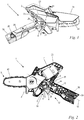
- Fig. 1 an inventive hand-held tool is shown, which is designed as a wood cutter in the embodiment.
- the working device 1 can also be designed, for example, as a hedge trimmer, motor saw, blower or the like.
- the work device 1 can also be designed as a work device with a shaft, for example as a pole pruner, hedge cutter, brush cutter, grass trimmer, brush cutter or the like.
- the tool 1 comprises a housing 23 with a handle 26.
- the handle 26 extends along its longitudinal axis 18 from its rear end 29 forwards in the direction of its front end 28. At the front end 28 is the handle 26 with the base body 73 of the housing 23 connected.
- the work device 1 comprises a tool 3 which, in the exemplary embodiment, has a guide rail 40 with a saw chain 42 Fig. 2 ) is.
- the guide rail 40 projects forward on the side of the housing 23 opposite the handle 26.
- a cut protection 41 is attached to the guide rail 40.
- a pivotable hood 74 is arranged on the housing 23, which hood extends along the guide rail 41 and at least partially projects beyond the guide rail 40.
- the hood 74 can be pivoted away from the guide rail 40 in an upward direction.
- the saw chain 42 which is driven by a drive motor 2 arranged in the housing 26, is arranged circumferentially on the guide rail 40.
- the drive motor 2 is designed as an electric motor which is fed with energy from a battery 39.
- the battery 39 is arranged at the rear end 29 of the handle 26.
- the electric motor can also be supplied with energy via a connection cable.
- the drive motor 2 can also be designed as an internal combustion engine, in particular as a two-stroke engine or a mixture-lubricated four-stroke engine.
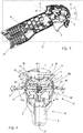
- the working device 1 comprises an actuating lever 4 for operating the drive motor 2 and a locking lever 5 for the actuating lever 4.
- the actuating lever 4 and the locking lever 5 are arranged on the housing 26 at the front end 28 of the handle 26.
- a blocking position 10 of the blocking lever 5 the actuating lever 4 is blocked by the blocking lever 5.
- the actuating lever 4 blocked by the locking lever 5 is in a non-actuated position.
- a release position 11, 11 'of the locking lever 5 the actuating lever 4 is released.
- the operator can move the actuating lever 4 into a working position 13 ( Figures 9, 10 ) Press and thus operate the drive motor 2.
- the locking lever 5 is pivotably mounted on the housing 23 about its axis of rotation 8 of the locking lever 5.
- the actuating lever 4 is mounted on the housing 23 so as to be pivotable about a pivot axis 9.
- the pivot axis 9 is perpendicular to a longitudinal plane 27 ( Fig. 3 ) of the handle 26, the longitudinal plane 27 containing the longitudinal axis 18 of the handle 26 and running parallel to the axis of rotation 8 of the locking lever 5.
- the term “parallel” also means that both the axis of rotation 8 of the locking lever 5 and the longitudinal axis 18 can be contained in the longitudinal plane 27.
- the locking lever 5 comprises a flag 37 with an end face 52, the flag 37 being arranged on the side of the locking lever 5 facing the actuating lever 4.
- the actuating lever 4 comprises a counter vane 38 with a counter face 53 which is arranged on the side of the actuating lever 4 facing the locking lever 5.
- the end face 52 of the vane 37 and the opposite end face 53 of the mating vane 38 are aligned facing one another in the blocking position 10. If the actuating lever 4 is pressed, the end face 52 and the opposing end face 53 contact each other, as a result of which pivoting of the actuating lever 4 about the pivot axis 9 is blocked.
- the locking lever 5 If the locking lever 5 is in a release position 11, 11 '( Figures 7, 8 ) pivoted, the locking lever 5 releases the actuating lever 4.
- the flag 37 of the locking lever 5 is moved out of the pivoting path of the counter-flag 38 of the actuating lever 4.
- the actuating lever 4 can be pivoted with its counter vane 38 about the pivot axis 9 without making contact with the vane 37 of the locking lever 5.
- the working device 1 comprises a switch 43 with a contact tongue 44 for actuating the drive motor 2.
- the actuating lever 4 pushes in the contact tongue 44, whereby the drive motor 2 is switched on.
- Such a switch 43 would be actuated directly by the actuating lever 4.
- the drive motor 2 can only be switched on or off via the actuating lever 4.
- the speed of the drive motor 2, which is designed as an electric motor is continuously adjustable via the actuating lever 4.
- the longitudinal axis 18 of the handle 26 forms an angle ⁇ with the axis of rotation 8 of the locking lever 5 in the direction of view perpendicular to the longitudinal plane 27.
- the angle ⁇ is in a range from 10 ° to 60 °, in particular from 15 ° to 45 °. In the exemplary embodiment, the angle ⁇ is in particular approximately 45 °. If the operator holds the implement 1 firmly by the handle 26, the operator can actuate the locking lever 5 with his thumb. The operator only has to perform a swiveling movement with his thumb.
- the longitudinal axis 18 is defined via a tangent lying on a center line of the handle 26 at the front end.
- the center line runs through the centroids of the individual cross-sectional planes of the handle 26 that are parallel to one another.
- the locking lever 5 comprises a hub 55, the locking lever 5 having two bearing journals 56 ( Fig. 6 ) is mounted pivotably about the axis of rotation 8 of the locking lever 5.
- the bearing pins 56 are advantageously formed on the locking lever 5.
- the bearing journals 56 can, however, also be formed by a separate shaft and can be rotatably mounted with respect to the housing 23 about the axis of rotation 8 of the locking lever 5.
- the locking lever 5 in the exemplary embodiment comprises two wall sections 58, 58 'which run in the shape of a segment of a circle.
- the wall sections 58, 58 ′ are connected to the hub 55 via a central web 59.
- the two wall sections 58, 58 ′ are arranged opposite one another in the blocking position 10 with respect to the longitudinal plane 27.
- the wall sections 58, 58 ' form a peripheral wall 14 of the locking lever 5 with a diameter d.
- the locking lever 5 comprises two lateral wing elements 24, 24 'for actuating the locking lever 5.
- the two lateral wing elements 24, 24' are arranged on the wall sections 58, 58 '.
- the two lateral wing elements 24, 24 ' are in particular formed in one piece with the wall sections 58, 58'.
- the lateral wing elements 24, 24 ' extend approximately perpendicular to the longitudinal plane 27 away from the peripheral wall 14 of the locking lever 5.
- the lateral wing elements 24, 24' protrude from openings 48, 48 'provided in the housing 23, whereby the locking lever 5 for the Operator outside the housing 23 is accessible.
- the wing elements 24, 24 ′ are arranged opposite one another on the locking lever 5 with respect to the longitudinal plane 27 of the handle 26.
- the wing elements 24, 24 ′ each have a width a measured perpendicular to the longitudinal plane 27.
- the width a corresponds to at least 15%, in particular at least 30%, preferably 38% of the diameter d of the locking lever 5.
- the width a of the wing elements 24, 24 ' corresponds to at most 50% of the diameter d of the locking lever 5.
- the wing elements 24, 24 ' have a wing upper side 46 facing away from the actuating element 4 and a wing lower side 47 facing the actuating element 4.
- the lateral wing elements 24, 24 ′ have a height b which corresponds to the distance between the wing underside 47 and the wing upper side 46, measured in the direction perpendicular to the axis of rotation 8 and parallel to the longitudinal plane 27.
- the height b corresponds to at most 20% of the diameter d of the locking lever 5.
- the lateral wing elements 24, 24 ′ lie with the axis of rotation 8 in one plane, the plane being oriented perpendicular to the longitudinal plane 27.
- the working device 1 comprises a spring unit 6.
- the spring unit 6 biases the locking lever 5 in the direction of the locking position 10.
- the locking lever 5 has a contour 15 which interacts with the spring unit 6.
- the contour 15 is formed from two legs 17, 17 ′ which are connected to one another in a lower section 16.
- the lower section 16 is the section of the contour 15 closest to the axis of rotation 8 and forms a depression of the contour 15 that extends towards the axis of rotation 8.
- the individual legs 17, 17 ' are arcuate.
- the locking lever 5 is designed such that the legs 17, 17 'in the locking position 10 extend in an arc from the upper ends of the wall sections 58, 58' facing away from the actuating lever 4 towards the longitudinal plane 27 and are supported on the hub 55 via a connecting web 35 are.
- the contour 15 is oriented such that the lower section 16 of the contour 15 is arranged towards the axis of rotation 8 of the locking lever 5 and the contour 15 is in it V-shape away from the axis of rotation 8 of the locking lever 5 opens.
- the longitudinal plane 27 runs centrally through the lower section 16.
- the angle ⁇ corresponds approximately to 100 °.
- the spring unit 6 rests against the contour 15 of the locking lever 5.
- the spring unit 6 acts with a spring force F F ( Fig. 5 ) on the contour 15 in the direction of the axis of rotation 8 of the locking lever 5.
- the pre-tensioning force vector which corresponds to the vector of the spring force F F , lies in the longitudinal plane 27.
- the contour 15 can also be designed such that the contour 15 in their V-shape opens downwards towards the axis of rotation 8.
- the spring unit 6 would be arranged between the axis of rotation 8 and the contour 15 and would act on the contour 15 away from the axis of rotation 8.
- the spring unit 6 is designed as a leaf spring in the exemplary embodiment.
- the spring unit 6 can also be designed as a leg spring or the like.
- the spring unit 6 is designed symmetrically with respect to the longitudinal plane 27.
- the locking lever 5 comprises a first pivoting direction 19 and a second pivoting direction 19 ′ opposite the first pivoting direction 19. If the locking lever 5, as in the Figures 7 to 10 shown, pivoted in one of the two pivoting directions 19, 19 'about the axis of rotation 8 of the locking lever 5, the spring unit 6 is pressed by the contour 15 of the locking lever 5 in the direction away from the axis of rotation 8 of the locking lever 5. The spring unit 6 slides along one of the two legs 17, 17 'of the contour 15, the spring force F F acting on the contour 15 of the locking lever 5 increasing. At the contact point between the spring unit 6 and the contour 15, a restoring force F R resulting from the spring force F F acts approximately normal to the surface on the contour 15.
- the restoring force F R causes a restoring moment M R that corresponds to the pivoting direction, in the exemplary embodiment the first pivoting direction 19, counteracts. If the operator releases the locking lever 5, no actuating force acts on the locking lever 5. Only the spring force F F acts through the Spring unit 6 on the locking lever 5. The restoring force F R resulting from the spring force F F causes the restoring torque M F , as a result of which the locking lever 5 is rotated back into the locking position 10.
- the spring unit 6 and the contour 15 generate an approximately constant restoring torque M R over the entire pivoting path of the locking lever.
- the resulting spring force F R increases .
- the contour 15, on the other hand flattens out with increasing radial distance from the axis of rotation 8 of the locking lever 5 in such a way that the direction of the restoring force F R is directed closer to the axis of rotation 8 of the locking lever 5. Consequently, the lever arm of the restoring force F R relative to the axis of rotation 8 of the locking lever 5 also decreases, as a result of which the restoring torque M R remains approximately constant.
- the contour 15 is preferably designed in such a way that when the locking lever 5 is pivoted over the entire pivoting range, an approximately constant restoring torque M R acts. In an alternative embodiment, however, the contour 15 can be designed in accordance with the desired restoring torque M R. Due to the symmetrical design of the legs 17, 17 'of the contour 15, the restoring force F R is also the same amount in terms of amount with the same deflection in the respective pivoting direction 19, 19'. This results in a particularly comfortable pivoting behavior for the operator in all pivoting directions 19, 19 'of the locking lever 5. The pivoting behavior of the locking lever 5 is the same regardless of which of the two lateral wing elements 24, 24 'is actuated and in which pivoting direction 19, 19' one of the two lateral wing elements 24, 24 'is pressed.
- the spring unit 6 in the exemplary embodiment comprises two mutually opposite spring legs 30 and 31, which are formed on the end of the spring unit 6 resting on the contour 15.
- the spring legs 30, 31 run in the direction away from the contour 15.
- the spring legs 30, 31 are designed as bent sections of the spring unit 6, whereby the spring unit 6 has a rounded contact surface with respect to the contour 15. This favors the sliding up and down of the spring unit 6 on the contour 15.
- the spring unit 6 has a width g, measured perpendicular to the longitudinal plane 27, which corresponds to at least 20% of the diameter d of the locking lever 5. Due to the wide design of the spring unit 6, the spring unit 6 rests in the blocking position 10 of the blocking lever 5 in two contact points on the contour 15, namely on one of the two legs 17, 17 'of the contour 15 ( Fig. 4 ). The spring unit 6, which is pretensioned in the direction of the axis of rotation 8 of the locking lever 5, thus exerts a restoring force F R on each of the two legs 17, 17 'of the contour 15. These restoring forces F R in turn cause opposing restoring torques M R.
- the spring unit 6 acts with the spring force F F on the locking lever 5 in the direction of the axis of rotation 8 of the locking lever 5. Due to the wide design of the spring unit 6, however, the force is applied to the contour 15 not in the direction of the axis of rotation 8 of the locking lever 5, but offset to this. As a result, large restoring torques M R can be generated even with small deflections of the locking lever 5.
- a lower edge 36, 36 'of the openings 48, 48' of the housing 23 serves as a rotary stop of the locking lever 5.
- the lower edge 36, 36 ' is the edge of the openings 48, 48' of the housing 23 that is closest to the actuating lever 4. If the locking lever 5 is arranged in the release position 11, 11 ', the lower edge 36, 36' of the opening 48, 48 'forms a stop for the wing element 24, 24'. Accordingly, the locking lever 5 can be rotated in the first pivoting direction 19 until the lateral wing element 24 with its upper wing 46 against the lower edge 36 of the opening 48 strikes. In an alternative embodiment, it can also be expedient to provide the upper edges of the openings 48, 48 'as a stop for the wing elements 24, 24'.
- the locking lever 5 is shown pivoted in the release position 11, and the actuating lever 4 is actuated and is in the working position 13.
- the flag 37 of the locking lever 5 and the counter-flag 38 of the actuating lever 4 do not make contact.
- the working device 1 comprises a spring element 7 which biases the actuating lever 4 in the direction of the non-actuated position 12.
- the spring element 7 is designed as a leg spring in the exemplary embodiment.
- the spring element 7 is designed symmetrically with respect to the longitudinal plane 27 in order to avoid undesirable tilting moments on the actuating lever 4.
- the spring element 7 comprises two spring legs 21, 21 ′, which are clamped on a component of the housing 23 and the actuating lever 4, the spring element 7 being supported via a central spring section 25 on the other component of the housing 23 and the actuating lever 4.
- the middle spring section 25 of the spring element 7 is on the housing 23 ( Fig. 6 ) clamped.
- the spring legs 21, 21 'of the spring element 7 are clamped at their ends 22, 22' on the actuating lever 4.
- the spring legs 21, 21 ′ are preferably additionally supported on the actuating lever 4 between their ends and the pivot axis 9.
- the turns of the spring element 7 are supported on a bearing journal 73 of the actuating lever 4, on which the actuating lever 4 is pivotably mounted. If no actuating force acts on the actuating lever 4, it is tensioned by the spring element 7 in the non-actuated position. In order to press the actuating lever 4 into the working position 13, the spring force of the spring element 7 must be overcome.
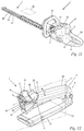
- Fig. 11 shows an alternative embodiment of an implement 1 according to the invention, namely a hedge trimmer.
- the same reference numerals as in the exemplary embodiment after the Figures 1 to 10 denote corresponding components.
- the working device 1 has, as tool 3, a cutter bar 60 with two cutting knives 61, 61 ′ which can be moved to and fro and which determine a cutting plane 62.
- a drive unit with the schematically illustrated drive motor 2 is received in the housing 23, which is fed via the rechargeable battery 39 plugged into the housing 23.
- the hedge trimmer is an electric hedge trimmer, especially a battery-operated hedge trimmer.
- the housing 23 has the handle 26, which is designed as a rear handle in the longitudinal direction of the implement 1.
- the locking lever 5 arranged on the housing 23 is only shown schematically in the form of a dashed rectangle.
- the actuating lever 4 is arranged on the housing 23.
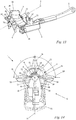
- Fig. 12 is a section of the part of the housing 23 of the implement 1 according to the invention
- Fig. 11 shown which includes the handle 26 and on which the locking lever 5 and the actuating lever 4 are arranged.
- the handle 26 merges at its rear end 29, that is to say the end of the handle 26 facing away from the locking lever 5, into a base body 73 of the housing 23.
- the work device 1 comprises a hand stop 50, via which the handle 26 merges at its front end 28 into the base body 73 of the housing 23.
- the hand stop 50 is formed on the housing 23 at the front end 28 of the handle 26 and extends away from the handle 26 in the direction from the actuating lever 4 to the handle 26.
- the hand stop 50 forms a stop for the hand of the operator towards the front in the direction of the longitudinal axis 18 of the handle 26.
- the hand stop 50 is used to rest the thumb saddle of the operator.
- the locking lever 5 is arranged adjacent to the hand stop 50.
- the longitudinal axis 18 of the handle 26 and the axis of rotation 8 of the locking lever 5 enclose the angle ⁇ , which opens away from the base body 73 of the housing 23.
- the angle ⁇ is in a range from 10 ° to 60 °, preferably from 15 ° to 45 °.
- the Angle ⁇ is in particular approximately 15 ° in the viewing direction perpendicular to the longitudinal plane 27.
- the locking lever 5 differs from the locking lever 5 according to the embodiment according to FIG Fig. 1 essentially in that the locking lever 5 has three wing elements 24, 24 ', 34 ( Fig. 14 ) having.
- the working device according to the invention with such a locking lever 5 with three wing elements 24, 24 ', 34 can also be designed in an alternative embodiment, for example as a motor saw, blower or the like.
- the work device 1 can also be designed as a work device with a shaft, for example as a pole pruner, hedge cutter, brush cutter, grass trimmer, brush cutter or the like.
- a further, upper wing element 34 is arranged on the locking lever 5 between the lateral wing elements 24, 24 ′.
- the wing elements 24, 24 ', 34 include an upper wing element 34 and two lateral wing elements 24, 24' in the direction of view of the longitudinal axis 18.
- the upper wing element 34 lies in the circumferential direction between the two lateral wing elements 24, 24 '.
- the upper wing element 34 of the three wing elements 24, 24 ′, 34 is arranged on the blocking lever 5 opposite the actuating lever 4 with respect to the axis of rotation 8 of the blocking lever 5.
- the two lateral wing elements 24, 24 'of the three wing elements 24, 24', 34 of the locking lever 5 are arranged opposite one another on the locking lever 5 with respect to the longitudinal plane 27, in particular mirror-symmetrically.
- the two lateral wing elements 24, 24 ′ of the locking lever 5 have the same angular spacing ⁇ about the axis of rotation 8 of the locking lever 5 from the upper wing element 34.
- the angular distance ⁇ is at least 60 °, in particular at least 70 °, preferably approximately 90 °.
- the wing elements 24, 24 ′, 34 are formed on the peripheral wall 14 of the locking lever 5. Accordingly, the wing elements 24, 24 ', 34 on the locking lever 5 are formed in one piece.
- the housing 23 has a groove 51 which extends at least 180 ° around the axis of rotation 8 of the locking lever 5.
- the locking lever 5 is arranged in the groove 51, the wing elements 24, 24 ′, 34 protruding from the groove 51 and thereby being easily accessible to the operator from outside the housing 23.
- the locking lever 5 has only one wall section 58, which is connected to a shaft 70 of the locking lever 5 via the central web 59 and the connecting web 35. All three wing elements 24, 24 ', 34 are formed on the wall section 58.
- the exemplary embodiment shown here for a working device 1 comprises one compared to the exemplary embodiment according to FIG Fig. 1 alternative design of a spring unit 6.
- the spring unit 6 biases the locking lever 5 in the direction of the locking position 10.
- the spring unit 6 is designed as a leaf spring, but in an alternative embodiment it can also be designed as a leg spring or the like, or it can comprise several springs.
- the spring unit 6 comprises a first spring leg 30 and a second spring leg 31.
- the spring legs 30, 31 are connected via an arcuate section 72 of the spring unit 6. Accordingly, the spring unit 6 has an approximately V-shape.
- the spring unit 6 is formed in one piece in the exemplary embodiment.
- the spring unit 6 is clamped on the locking lever 5.
- the spring legs 30, 31 protrude from the circumferential wall of the locking lever 5 and, in the locking position, are directed towards the actuating lever 4.
- the arcuate section 72 of the spring unit 6 runs around part of the circumference of the shaft 70 of the locking lever 5.
- the spring unit 6 is also clamped on the locking lever 5 via three guides 54. There two of the three guides 54 are formed opposite one another on the central web 59 with respect to the longitudinal plane 27.
- the further guide 54 is formed on the connecting web 35 of the locking lever 5.
- the guides 54 are each designed as a slot, in particular as an opening.
- the spring unit is clamped in a pretensioned manner in the guides 54, in particular in the guides 54 provided on the central web 59.
- the housing 23 forms a first rotary stop 32 and a second rotary stop 33.
- a first stop surface 68 and a second stop surface 69 are formed on the locking lever 5.
- the stop surfaces 68, 69 are formed at the ends of the wall section 58.
- the spring unit 6 is arranged opposite the housing 23 in such a way that when the locking lever 5 is pivoted in the first pivoting direction 19, the first spring leg 30 of the spring unit 6 is deflected by the first stop surface 68 of the locking lever 5 in the direction of the longitudinal plane 27.
- the spring unit 6 is supported via the second spring leg 31 on the second rotary stop 33 of the housing 23 ( Fig. 15 ).
- the spring unit 6 acts on the stop surface 68 of the locking lever 5 with a spring force.
- the second spring leg 31 lies approximately flat against the stop surface 68, whereby the spring force corresponds approximately to the restoring force F R acting on the locking lever.
- the restoring force F R in turn generates the restoring torque M R , by means of which the locking lever 5 is pivoted from the release position 11 back into the locking position 10. If the locking lever 5 is deflected in the second pivoting direction 19 ′, the second spring leg 31 is deflected via the second stop surface 69 of the locking lever 5 in the direction of the longitudinal plane 27.
- the spring unit 6 is supported via the first spring leg 30 on the first rotary stop 32 of the housing 23 ( Fig. 16 ).
- the formation of the acting forces takes place analogously to the first spring leg 30.
- the restoring force F R is the same amount in both pivoting directions 19, 19 'with the same amount of deflection.
- the spring unit 6 is designed symmetrically to the longitudinal plane 27.
- the locking lever 5 is also designed symmetrically to the longitudinal plane 27. This will be for the two different pivoting directions 19, 19 'generates restoring forces F R of equal magnitude and restoring torques M R of equal magnitude.
- a pole pruner is shown as an alternative embodiment of an implement 1 according to the invention.
- the same reference numerals according to the exemplary embodiment according to FIGS Figures 1 to 10 as well as the embodiment according to Figures 11 to 16 denote corresponding components.
- the work device 1 comprises the drive unit, which is connected to a cutting head 65 via a shaft which comprises a guide tube 64.
- the shaft or the guide tube 64 form part of the housing 23.
- the drive unit is arranged in the housing 23 and comprises the drive motor 2 shown schematically.
- the drive motor 2 is designed as an internal combustion engine in the exemplary embodiment.
- the drive motor 2 is an electric motor.
- the drive motor 2 is arranged on the cutting head 65, in particular when the drive motor 2 is an electric motor.
- a rechargeable battery 39 for supplying the drive motor 2 with energy can then be provided in the housing 23.
- the guide tube 64 is designed as a telescopic tube in the exemplary embodiment.
- the guide tube 64 has a first end 66 to which the drive unit is fixed. Adjacent to the first end 66 of the guide tube 64, the handle 26 is fixed on the guide tube 64.
- the actuating lever 4 and the schematically illustrated locking lever 5 are mounted on the handle 26.
- the cutting head 65 is arranged at a second end 67 of the guide tube 64.
- a drive shaft can protrude through the guide tube 64 when the drive motor 2 is arranged in the base body 73 of the housing 23. If the drive motor 2 is arranged on the cutting head 65, power and signal lines advantageously run through the guide tube 64.
- FIGS 18 and 19 are in a lateral, partial sectional view of the implement 1 according to Figure 17 the guide tube 64, the handle 26 and the actuating lever 4 and the locking lever 5 are shown. Also in this according to the invention Embodiment of the implement 1 enclose the longitudinal axis 18 of the handle 26 and the axis of rotation 8 of the locking lever 5 in the direction of view perpendicular to the longitudinal plane 27 at the angle ⁇ .
- the angle ⁇ is in a range between 10 ° and 60 °, preferably between 15 ° and 45 °. In the exemplary embodiment, the angle ⁇ is in particular approximately 15 °.
- the locking lever 5 has a shaft 70 which is mounted in the housing 23 so as to be pivotable about the axis of rotation 8 of the locking lever 5.
- the wall section 58 is connected to the shaft 70 via the connecting web 35.
- the connecting web 35 lies in the locking position 10 of the locking lever 5 in the longitudinal plane 27.
- the shaft 70 and the locking lever 5 are formed in one piece.
- the shaft 70 comprises an extension on which the flag 37 is formed.
- the actuating lever 4 is blocked in its pivoting direction for actuating the drive motor 2 by the flag 37 of the shaft 70.
- the three wing elements 24, 24 ', 34 are formed on the locking lever 5.
- the locking lever 5 differs from that in Fig. 12 locking lever 5 shown in that in locking position 10 both the maximum distance e and the minimum distance f between the lateral wing elements 24, 24 'and the axis of rotation 8 of the locking lever 5 is greater.
- the maximum distance e corresponds to at least 15%, preferably at least 25%, in particular approximately 30% of the diameter d of the locking lever 5.
- the minimum distance f corresponds to at least 5%, in particular at least 10% of the diameter d of the locking lever 5.
- the wall section 58 extends over the angle ⁇ ( Fig. 22 ) about the axis of rotation 8 of the locking lever 5, the angle ⁇ being at least 180 °, in particular at least 200 °, preferably approximately 250 °.
- Such tools 1 with a shaft are used for cutting operations on trees or high hedges.
- the operator holds the implement 1 in such a way that the shaft points upwards.
- the handle 26 must be held in an angled position. It has been shown that it is comfortable for the operator if the thumb is at a large distance from the axis of rotation 8 of the locking lever 5 in the direction of the actuating lever 4. Due to the deep arrangement of the lateral wing elements 24, 24 'on the locking lever 5, the distances e, f of the lateral wing elements 24, 24' to the axis of rotation of the locking lever 5 are significantly increased. This results in a relaxed grip position for the operator, in particular with an angled hand position.
- the spring unit 6 is shown, which in its installation position compared to the spring unit of the embodiment according to Fig. 12 differs.
- the spring unit 6 also has a first spring leg 30 and a second spring leg 31, which are connected to one another via an arcuate section 72.
- the spring unit 6 has an approximately V-shape. However, the spring unit 6 is installed rotated by 180 ° with respect to the axis of rotation 8 of the locking lever 5.
- the spring legs 30, 31 run away from the actuating lever 4 in the direction of the upper wing element 34.
- the spring unit 6 is clamped between the shaft 70 of the locking lever 5 and a shaft receptacle 57 provided for the locking lever 5.
- the spring legs 30, 31 extend approximately to the inside of the locking lever 5.
- the first rotary stop 32 and the second rotary stop 33 are formed by the housing 23, in particular by the base body of the housing 23 or by recesses in the guide tube 64.
- the housing 23 extends Via two webs 71, 71 'into the interior of the locking lever 5.
- the webs 71, 71' are formed opposite one another with respect to the longitudinal plane 27.
- the two webs 71, 71 ' extend approximately as far as the two stop surfaces 68, 69, but without contacting them.
- the rotary stops 32, 33 are formed at the ends of the webs 71, 71 '.
- the rotary stops 32, 33 are formed either by the base body of the housing 23 or by the guide tube 64.
- the first rotary stop 32 blocks the rotary movement of the first spring leg 30 in the second pivoting direction 19 '.
- the spring unit 6 effects a restoring force F R on the locking lever 5 via its second spring leg 31, which force F R biases the locking lever 5 back into its locking position 10.
- the first spring leg 30 is supported on the first rotary stop 32, the second spring leg 32 acting on the locking lever 5 via the first stop surface 68 of the locking lever 5.
- the second rotary stop 33 limits a rotary movement of the second spring leg 31 in the first pivoting direction 19.
- the second spring leg 31 is correspondingly deflected at the second rotary stop 33.
- the first spring leg 30 causes a restoring force F R , which biases the locking lever 5 back into the locking position 10 counter to the first pivoting direction 19 via the second stop surface 69, the first spring leg 30 being supported on the first rotary stop 32.
- the spring legs 30, 31 are clamped on the stop surfaces 68, 69 formed on the inside of the locking lever 5.
- the spring unit 6 is pretensioned in a clamped manner, in particular between the shaft 70 and the shaft receptacle 57 and between the two stop surfaces 68, 69.
Priority Applications (1)
| Application Number | Priority Date | Filing Date | Title |
|---|---|---|---|
| EP20197561.2A EP3792009B1 (fr) | 2019-09-12 | 2019-09-12 | Appareil de travail portatif doté d'un outil |
Applications Claiming Priority (2)
| Application Number | Priority Date | Filing Date | Title |
|---|---|---|---|
| EP19197112.6A EP3792006A1 (fr) | 2019-09-12 | 2019-09-12 | Appareil de travail portatif doté d'un outil |
| EP20197561.2A EP3792009B1 (fr) | 2019-09-12 | 2019-09-12 | Appareil de travail portatif doté d'un outil |
Related Parent Applications (2)
| Application Number | Title | Priority Date | Filing Date |
|---|---|---|---|
| EP19197112.6A Division EP3792006A1 (fr) | 2019-09-12 | 2019-09-12 | Appareil de travail portatif doté d'un outil |
| EP19197112.6A Division-Into EP3792006A1 (fr) | 2019-09-12 | 2019-09-12 | Appareil de travail portatif doté d'un outil |
Publications (2)
| Publication Number | Publication Date |
|---|---|
| EP3792009A1 true EP3792009A1 (fr) | 2021-03-17 |
| EP3792009B1 EP3792009B1 (fr) | 2024-04-24 |
Family
ID=67953708
Family Applications (3)
| Application Number | Title | Priority Date | Filing Date |
|---|---|---|---|
| EP19197112.6A Pending EP3792006A1 (fr) | 2019-09-12 | 2019-09-12 | Appareil de travail portatif doté d'un outil |
| EP20197561.2A Active EP3792009B1 (fr) | 2019-09-12 | 2019-09-12 | Appareil de travail portatif doté d'un outil |
| EP20197560.4A Active EP3792008B1 (fr) | 2019-09-12 | 2019-09-12 | Appareil de travail portatif doté d'un outil |
Family Applications Before (1)
| Application Number | Title | Priority Date | Filing Date |
|---|---|---|---|
| EP19197112.6A Pending EP3792006A1 (fr) | 2019-09-12 | 2019-09-12 | Appareil de travail portatif doté d'un outil |
Family Applications After (1)
| Application Number | Title | Priority Date | Filing Date |
|---|---|---|---|
| EP20197560.4A Active EP3792008B1 (fr) | 2019-09-12 | 2019-09-12 | Appareil de travail portatif doté d'un outil |
Country Status (3)
| Country | Link |
|---|---|
| US (1) | US11958155B2 (fr) |
| EP (3) | EP3792006A1 (fr) |
| CN (1) | CN112470737A (fr) |
Families Citing this family (10)
| Publication number | Priority date | Publication date | Assignee | Title |
|---|---|---|---|---|
| USD932268S1 (en) * | 2020-11-04 | 2021-10-05 | Shenghui Liao | Pruning saw |
| USD926007S1 (en) * | 2020-12-29 | 2021-07-27 | Yongkang Huiyan Industry and Trade Co., Ltd. | Chainsaw |
| US20220288765A1 (en) * | 2021-03-15 | 2022-09-15 | Andreas Stihl Ag & Co. Kg | Hand- guided work apparatus |
| USD959945S1 (en) * | 2021-06-22 | 2022-08-09 | Jimin Lin | Mini chainsaw |
| USD957225S1 (en) * | 2021-07-04 | 2022-07-12 | Hefei Qiongzhi Network Technology Co., Ltd. | Mini chainsaw |
| USD1020421S1 (en) * | 2021-08-25 | 2024-04-02 | Jinhua Bochao Tools Co., Ltd | Lithium battery-powered chainsaw |
| WO2024051895A1 (fr) | 2022-09-09 | 2024-03-14 | Andreas Stihl Ag & Co. Kg | Scie de jardin |
| DE102022123061A1 (de) | 2022-09-09 | 2024-03-14 | Andreas Stihl Ag & Co. Kg | Gehölzschneider |
| DE102022123203A1 (de) | 2022-09-12 | 2024-03-14 | Andreas Stihl Ag & Co. Kg | Handgeführtes Arbeitsgerät |
| USD1005075S1 (en) * | 2023-03-29 | 2023-11-21 | Jinyun Mailin Tools Co., Ltd | Chainsaw |
Citations (3)
| Publication number | Priority date | Publication date | Assignee | Title |
|---|---|---|---|---|
| US5988241A (en) * | 1998-11-16 | 1999-11-23 | Porter-Cable Corporation | Ergonomic router handles |
| EP1759813A2 (fr) * | 2002-01-10 | 2007-03-07 | Black & Decker, Inc. | Meuleuse d'angle |
| EP2202035A2 (fr) * | 2008-12-26 | 2010-06-30 | Omron Co., Ltd. | Outil électrique |
Family Cites Families (19)
| Publication number | Priority date | Publication date | Assignee | Title |
|---|---|---|---|---|
| DE3033604A1 (de) * | 1980-09-06 | 1982-04-22 | Fa. Andreas Stihl, 7050 Waiblingen | Motorsaege |
| DE4102482A1 (de) * | 1991-01-29 | 1992-07-30 | Bosch Gmbh Robert | Handwerkzeugmaschine |
| DE4411002A1 (de) * | 1994-03-30 | 1995-10-05 | Bosch Gmbh Robert | Gerät zum Schneiden von Pflanzen |
| US6091035A (en) | 1998-08-14 | 2000-07-18 | Black & Decker, Inc. | Lockout mechanism for power tool |
| DE10323544B4 (de) | 2003-05-24 | 2005-10-27 | Preh Gmbh | Rasteinrichtung für ein dreheinstellbares, elektrisches Bauelement |
| DE10353013A1 (de) * | 2003-11-13 | 2005-06-16 | Robert Bosch Gmbh | Handwerkzeugmaschine |
| US7708085B2 (en) * | 2005-11-04 | 2010-05-04 | Robert Bosch Gmbh | Articulating drill with optical speed control and method of operation |
| US7538503B2 (en) * | 2006-04-21 | 2009-05-26 | Andreas Stihl Ag & Co. Kg | Hand-held power tool, in particular a trimmer or the like, having an electric drive motor |
| JP2007299602A (ja) | 2006-04-28 | 2007-11-15 | Tokai Rika Co Ltd | ロータリースイッチ装置 |
| DE102006047451B4 (de) * | 2006-10-07 | 2021-11-04 | Andreas Stihl Ag & Co. Kg | Handgeführtes Arbeitsgerät |
| DE102010054653B4 (de) * | 2010-12-15 | 2022-03-03 | Andreas Stihl Ag & Co. Kg | Handgeführte Heckenschere |
| US8723060B2 (en) * | 2011-12-21 | 2014-05-13 | Robert Bosch Tool Corporation | Method and mechanism for power tool lock-off |
| ES2564015T3 (es) * | 2011-12-22 | 2016-03-17 | Black & Decker Inc. | Dispositivo de corte de vegetación |
| DE102011089722A1 (de) | 2011-12-23 | 2013-06-27 | Robert Bosch Gmbh | Werkzeugmaschine |
| CN104012242B (zh) * | 2013-02-28 | 2018-02-13 | 安德烈亚斯.斯蒂尔两合公司 | 手持式工作器械 |
| DE102013009891A1 (de) * | 2013-06-13 | 2014-12-18 | Andreas Stihl Ag & Co. Kg | Arbeitsgerät mit einem Verbrennungsmotor |
| US10014128B2 (en) * | 2013-12-17 | 2018-07-03 | Robert Bosch Tool Corporation | Portable power tool with trigger switch, trigger release and lock-on mechanism combination |
| DE102014009144A1 (de) * | 2014-06-20 | 2015-12-24 | Andreas Stihl Ag & Co. Kg | Handgeführtes Arbeitsgerät |
| CN206471261U (zh) | 2017-01-16 | 2017-09-05 | 德利威电子股份有限公司 | 可复位的旋钮开关 |
-
2019
- 2019-09-12 EP EP19197112.6A patent/EP3792006A1/fr active Pending
- 2019-09-12 EP EP20197561.2A patent/EP3792009B1/fr active Active
- 2019-09-12 EP EP20197560.4A patent/EP3792008B1/fr active Active
-
2020
- 2020-09-11 CN CN202010953953.5A patent/CN112470737A/zh active Pending
- 2020-09-14 US US17/020,482 patent/US11958155B2/en active Active
Patent Citations (3)
| Publication number | Priority date | Publication date | Assignee | Title |
|---|---|---|---|---|
| US5988241A (en) * | 1998-11-16 | 1999-11-23 | Porter-Cable Corporation | Ergonomic router handles |
| EP1759813A2 (fr) * | 2002-01-10 | 2007-03-07 | Black & Decker, Inc. | Meuleuse d'angle |
| EP2202035A2 (fr) * | 2008-12-26 | 2010-06-30 | Omron Co., Ltd. | Outil électrique |
Also Published As
| Publication number | Publication date |
|---|---|
| EP3792008A1 (fr) | 2021-03-17 |
| US20210078123A1 (en) | 2021-03-18 |
| CN112470737A (zh) | 2021-03-12 |
| EP3792008B1 (fr) | 2024-05-01 |
| US11958155B2 (en) | 2024-04-16 |
| EP3792006A1 (fr) | 2021-03-17 |
| EP3792009B1 (fr) | 2024-04-24 |
Similar Documents
| Publication | Publication Date | Title |
|---|---|---|
| EP3792008B1 (fr) | Appareil de travail portatif doté d'un outil | |
| DE60005718T2 (de) | Griff für Mähgerät | |
| DE19745306C2 (de) | Handgriffanordnung für einen Winkelschleifer | |
| EP0176784B1 (fr) | Sécateur pour arbres | |
| DE60107760T2 (de) | Schneidegerät, insbesondere Heckenschere | |
| EP0421108A1 (fr) | Cisailles à main, en particulier sécateur, cisailles à haies et/ou de jardinage | |
| DE3531059A1 (de) | Motorisch betriebenes handgeraet | |
| EP0347869B1 (fr) | Outil de coupe à moteur portable, notamment scie à chaîne ou cisaille à haies | |
| EP0102954A1 (fr) | Outil ou jeu d'outils. | |
| DE2816485C2 (de) | Handgriffausbildung an einem tragbaren kraftbetriebenen Werkzeug, insbesondere Motorsäge, Heckenschere od. dgl. | |
| DE3136143A1 (de) | Arbeitsgeraet, insbesondere haus- und gartengeraet mit einem antriebsmotor | |
| EP1782682A2 (fr) | Appareil de travail guidé manuellement | |
| DE10332918A1 (de) | Fadenschneider | |
| EP3760025A1 (fr) | Dispositif de commande à poignée et appareil de travail entraîné par un moteur | |
| EP1884156B1 (fr) | Machine-outil électronique commandée à la main tout comme couplage d'une machine-outil électronique commandée à la main | |
| EP1466690A1 (fr) | Scie sauteuse en forme de sabre avec dispositif d'ajustage pour un guide | |
| DE19926375A1 (de) | Motorbetriebenes Gartenwerkzeug, insbesondere Heckenschere | |
| WO1995009072A1 (fr) | Poignee pour outils a moteur | |
| EP3892082A1 (fr) | Poignée pour un appareil de travail guidé à la main et débroussailleuse | |
| EP1661447A1 (fr) | Débroussailleuse | |
| DE3310706A1 (de) | Elektrische haarschneidemaschine | |
| EP0618050B1 (fr) | Rabot à main | |
| DE3633655A1 (de) | Tragbare kreissaege | |
| EP0826299B1 (fr) | Taille-haie | |
| WO2008110266A2 (fr) | Ciseaux à pelouse comportant un dispositif de préhension |
Legal Events
| Date | Code | Title | Description |
|---|---|---|---|
| PUAI | Public reference made under article 153(3) epc to a published international application that has entered the european phase |
Free format text: ORIGINAL CODE: 0009012 |
|
| STAA | Information on the status of an ep patent application or granted ep patent |
Free format text: STATUS: THE APPLICATION HAS BEEN PUBLISHED |
|
| AC | Divisional application: reference to earlier application |
Ref document number: 3792006 Country of ref document: EP Kind code of ref document: P |
|
| AK | Designated contracting states |
Kind code of ref document: A1 Designated state(s): AL AT BE BG CH CY CZ DE DK EE ES FI FR GB GR HR HU IE IS IT LI LT LU LV MC MK MT NL NO PL PT RO RS SE SI SK SM TR |
|
| AX | Request for extension of the european patent |
Extension state: BA ME |
|
| RIN1 | Information on inventor provided before grant (corrected) |
Inventor name: MANN, VERENA Inventor name: MANDEL, ROLAND Inventor name: MAIER, THOMAS Inventor name: KERN, FRANZISKA Inventor name: OBERHOFER, FELIX Inventor name: JENKE, MARCUS Inventor name: POSNER, BENEDIKT Inventor name: BATHKE, LARS |
|
| STAA | Information on the status of an ep patent application or granted ep patent |
Free format text: STATUS: REQUEST FOR EXAMINATION WAS MADE |
|
| 17P | Request for examination filed |
Effective date: 20210907 |
|
| RBV | Designated contracting states (corrected) |
Designated state(s): AL AT BE BG CH CY CZ DE DK EE ES FI FR GB GR HR HU IE IS IT LI LT LU LV MC MK MT NL NO PL PT RO RS SE SI SK SM TR |
|
| GRAP | Despatch of communication of intention to grant a patent |
Free format text: ORIGINAL CODE: EPIDOSNIGR1 |
|
| STAA | Information on the status of an ep patent application or granted ep patent |
Free format text: STATUS: GRANT OF PATENT IS INTENDED |
|
| INTG | Intention to grant announced |
Effective date: 20231122 |
|
| RIN1 | Information on inventor provided before grant (corrected) |
Inventor name: POSNER, BENEDIKT Inventor name: MANDEL, ROLAND Inventor name: BATHKE, LARS Inventor name: MANN, VERENA Inventor name: MAIER, THOMAS Inventor name: KERN, FRANZISKA Inventor name: JENKE, MARCUS Inventor name: OBERHOFER, FELIX |
|
| GRAS | Grant fee paid |
Free format text: ORIGINAL CODE: EPIDOSNIGR3 |
|
| GRAA | (expected) grant |
Free format text: ORIGINAL CODE: 0009210 |
|
| STAA | Information on the status of an ep patent application or granted ep patent |
Free format text: STATUS: THE PATENT HAS BEEN GRANTED |
|
| AC | Divisional application: reference to earlier application |
Ref document number: 3792006 Country of ref document: EP Kind code of ref document: P |
|
| AK | Designated contracting states |
Kind code of ref document: B1 Designated state(s): AL AT BE BG CH CY CZ DE DK EE ES FI FR GB GR HR HU IE IS IT LI LT LU LV MC MK MT NL NO PL PT RO RS SE SI SK SM TR |
|
| REG | Reference to a national code |
Ref country code: GB Ref legal event code: FG4D Free format text: NOT ENGLISH |
|
| REG | Reference to a national code |
Ref country code: CH Ref legal event code: EP |
|
| REG | Reference to a national code |
Ref country code: DE Ref legal event code: R096 Ref document number: 502019011141 Country of ref document: DE |