EP3789544A1 - Antriebsanordnung für baumaschine - Google Patents
Antriebsanordnung für baumaschine Download PDFInfo
- Publication number
- EP3789544A1 EP3789544A1 EP20192463.6A EP20192463A EP3789544A1 EP 3789544 A1 EP3789544 A1 EP 3789544A1 EP 20192463 A EP20192463 A EP 20192463A EP 3789544 A1 EP3789544 A1 EP 3789544A1
- Authority
- EP
- European Patent Office
- Prior art keywords
- driving arrangement
- hydraulic pump
- electric motor
- base portion
- construction machine
- Prior art date
- Legal status (The legal status is an assumption and is not a legal conclusion. Google has not performed a legal analysis and makes no representation as to the accuracy of the status listed.)
- Withdrawn
Links
- 238000010276 construction Methods 0.000 title claims abstract description 36
- 230000033001 locomotion Effects 0.000 claims abstract description 6
- 238000013016 damping Methods 0.000 claims description 15
- 230000008878 coupling Effects 0.000 claims description 9
- 238000010168 coupling process Methods 0.000 claims description 9
- 238000005859 coupling reaction Methods 0.000 claims description 9
- 238000005728 strengthening Methods 0.000 description 11
- 229910000831 Steel Inorganic materials 0.000 description 2
- 238000002485 combustion reaction Methods 0.000 description 2
- 230000001747 exhibiting effect Effects 0.000 description 2
- 239000000463 material Substances 0.000 description 2
- 239000010959 steel Substances 0.000 description 2
- 238000003466 welding Methods 0.000 description 2
- 230000003247 decreasing effect Effects 0.000 description 1
- 239000013013 elastic material Substances 0.000 description 1
- 238000013017 mechanical damping Methods 0.000 description 1
- 230000035939 shock Effects 0.000 description 1
- 230000001360 synchronised effect Effects 0.000 description 1
Images

Classifications
-
- E—FIXED CONSTRUCTIONS
- E02—HYDRAULIC ENGINEERING; FOUNDATIONS; SOIL SHIFTING
- E02F—DREDGING; SOIL-SHIFTING
- E02F9/00—Component parts of dredgers or soil-shifting machines, not restricted to one of the kinds covered by groups E02F3/00 - E02F7/00
- E02F9/20—Drives; Control devices
- E02F9/202—Mechanical transmission, e.g. clutches, gears
-
- E—FIXED CONSTRUCTIONS
- E02—HYDRAULIC ENGINEERING; FOUNDATIONS; SOIL SHIFTING
- E02F—DREDGING; SOIL-SHIFTING
- E02F3/00—Dredgers; Soil-shifting machines
- E02F3/04—Dredgers; Soil-shifting machines mechanically-driven
- E02F3/28—Dredgers; Soil-shifting machines mechanically-driven with digging tools mounted on a dipper- or bucket-arm, i.e. there is either one arm or a pair of arms, e.g. dippers, buckets
- E02F3/36—Component parts
- E02F3/42—Drives for dippers, buckets, dipper-arms or bucket-arms
-
- E—FIXED CONSTRUCTIONS
- E02—HYDRAULIC ENGINEERING; FOUNDATIONS; SOIL SHIFTING
- E02F—DREDGING; SOIL-SHIFTING
- E02F9/00—Component parts of dredgers or soil-shifting machines, not restricted to one of the kinds covered by groups E02F3/00 - E02F7/00
- E02F9/20—Drives; Control devices
-
- E—FIXED CONSTRUCTIONS
- E02—HYDRAULIC ENGINEERING; FOUNDATIONS; SOIL SHIFTING
- E02F—DREDGING; SOIL-SHIFTING
- E02F9/00—Component parts of dredgers or soil-shifting machines, not restricted to one of the kinds covered by groups E02F3/00 - E02F7/00
- E02F9/08—Superstructures; Supports for superstructures
- E02F9/0808—Improving mounting or assembling, e.g. frame elements, disposition of all the components on the superstructures
-
- E—FIXED CONSTRUCTIONS
- E02—HYDRAULIC ENGINEERING; FOUNDATIONS; SOIL SHIFTING
- E02F—DREDGING; SOIL-SHIFTING
- E02F9/00—Component parts of dredgers or soil-shifting machines, not restricted to one of the kinds covered by groups E02F3/00 - E02F7/00
- E02F9/08—Superstructures; Supports for superstructures
- E02F9/0858—Arrangement of component parts installed on superstructures not otherwise provided for, e.g. electric components, fenders, air-conditioning units
- E02F9/0866—Engine compartment, e.g. heat exchangers, exhaust filters, cooling devices, silencers, mufflers, position of hydraulic pumps in the engine compartment
-
- E—FIXED CONSTRUCTIONS
- E02—HYDRAULIC ENGINEERING; FOUNDATIONS; SOIL SHIFTING
- E02F—DREDGING; SOIL-SHIFTING
- E02F9/00—Component parts of dredgers or soil-shifting machines, not restricted to one of the kinds covered by groups E02F3/00 - E02F7/00
- E02F9/20—Drives; Control devices
- E02F9/2058—Electric or electro-mechanical or mechanical control devices of vehicle sub-units
-
- E—FIXED CONSTRUCTIONS
- E02—HYDRAULIC ENGINEERING; FOUNDATIONS; SOIL SHIFTING
- E02F—DREDGING; SOIL-SHIFTING
- E02F9/00—Component parts of dredgers or soil-shifting machines, not restricted to one of the kinds covered by groups E02F3/00 - E02F7/00
- E02F9/20—Drives; Control devices
- E02F9/22—Hydraulic or pneumatic drives
Definitions
- the present invention relates to a driving arrangement for a construction machine, and to a construction machine comprising such a driving arrangement.
- the construction machine may be an excavator.
- Electrical excavators which comprise an electrical storage device for powering an electrical motor, the electrical motor driving a hydraulic pump via which hydraulic actuators of the excavator's boom may be actuated.
- CN 10 496 337 5 A relates to an excavator comprising an electric motor and a hydraulic pump.
- the present invention relates to a driving arrangement for a construction machine.
- the construction machine may be an excavator or any other type of construction machine.
- the excavator may comprise an undercarriage and a superstructure, which is pivotably provided on the undercarriage.
- the undercarriage may comprise one or multiple tracks for locomotion of the excavator, i.e. for moving the excavator forwards, backwards and/or sidewards.
- the construction machine e.g. the superstructure of the excavator, may comprise a boom with multiple arms, which are movable with respect to each other via hydraulic actuators.
- the hydraulic actuators may be part of a hydraulic circuit of the construction machine.
- the driving arrangement of the present invention comprises a hydraulic pump for powering a working equipment and/or locomotion of the construction machine through a hydraulic circuit.
- the hydraulic pump is suitable for powering the above-described hydraulic circuit comprising the multiple hydraulic actuators for moving the multiple arms of the construction machine's boom.
- the hydraulic pump may be configured to power a further hydraulic circuit via which means for locomotion of the excavator, e.g. tracks, may be driven.
- the driving arrangement comprises an electric motor for driving the hydraulic pump via a connection means.
- the electric motor is configured, e.g. exhibits an output torque/power, suitable for driving the hydraulic pump.
- the electric motor may be a synchronous or asynchronous motor.
- the driving arrangement comprises only this one electric motor for driving the hydraulic pump, implying that the hydraulic pump is not driven by any other power source, in particular not by a combustion engine.
- the electric motor may be powered by an electrical storage unit, which may comprise multiple battery packs, wherein each battery pack may comprise multiple battery cells.
- Each of the battery packs may be configured to provide a current of multiple hundreds of Ampere, e.g. at a rated voltage of approximately 100V.
- the construction machine e.g. the excavator, may be a pure electric excavator only comprising an electrical storage device as power source, in particular not comprising a combustion engine.
- the driving arrangement comprises a supporting device suitable to mount the driving arrangement to the construction machine.
- the supporting device may be made from multiple components, which may be connected to each other via material bonding, e.g. welding, and/or bolts/screws or which may be integrally formed with each other.
- the supporting device may be made from steel.
- the supporting device supports the hydraulic pump and the electric motor. Specifically, the hydraulic pump and the electric motor are mounted to the supporting device.
- the driving arrangement comprises an adjustment mechanism for adjusting the positional relationship between the electric motor and the hydraulic pump to align both components with respect to each other.
- the adjustment mechanism may be provided by the supporting device and/or by a separate arrangement. The positional relationship may be adjusted by displacing the electric motor and the hydraulic pump with respect to each other in a linear fashion and/or by rotating both components with respect to each other.
- the driving arrangement of the present invention is simple and easy to assemble, as the positional relationship between the hydraulic pump and the electric motor can be easily adapted, e.g. to align the shaft of the electric motor with the shaft of the hydraulic pump before coupling both parts together with the connection means.
- costs of the driving arrangement can be decreased significantly, as larger tolerances are acceptable, for example.
- connection means is configured as an elastic coupling.
- the elastic coupling may be an elastic material which is elastically deformable by loads applied thereto during the intended use of the driving arrangement.
- the elastic coupling may be a mechanical or a hydraulic coupling. Configuring the connection means as an elastic coupling results in high operational stability, as disturbances applied to one of the components are not directly transferred to the other one via the connection means.
- the adjustment mechanism of the driving arrangement of the present invention is particularly advantageous, as it allows for an easy alignment of the shafts of electric motor and hydraulic pump with respect to each other.
- the adjustment mechanism may be configured to allow for an adjustment of the positional relationship between the electric motor and the hydraulic pump in two different directions.
- said two directions are oriented perpendicular to each other and/or correspond to the vertical and depth direction of the driving arrangement.
- the vertical direction may correspond to the vertical direction of the construction machine when the driving arrangement is mounted thereto in the intended fashion.
- a length direction of the driving arrangement may run parallel to the shaft of the electric motor and/or the hydraulic pump and/or may be perpendicular to the vertical direction.
- a depth direction may be defined as being perpendicular to both the length and vertical directions of the driving arrangement. This embodiment allows for an effective and precise alignment of the electric motor and the hydraulic pump.
- the supporting device comprises a base portion, which may be formed in a plate-like shape.
- a plate-like shape may exhibit extensions in two directions, which are perpendicular to each other, which are significantly larger than the extension of the portion in a third direction, which is perpendicular to the other two directions.
- One of the hydraulic pump and the electric motor may be provided stationary with respect to the base portion and the other one of the hydraulic pump and the electric motor may be provided displaceable with respect to the base portion via the adjustment mechanism.
- the hydraulic pump is fixedly connected to the base portion and the electric motor is provided in a displaceable fashion.
- the supporting device may comprise a mounting portion, which is attached to the displaceable one of the hydraulic pump and the electric motor.
- the mounting portion is connected to the base portion in a displaceable manner, e.g. via an adjustment screw.
- the mounting portion may be integrally formed from a single component or from multiple components, which are connected to each other, e.g. via material bonding, in particular via welding.
- the mounting portion is connected to the base portion via multiple adjustment screws.
- This embodiment provides a driving arrangement with an adjustment mechanism exhibiting low complexity and being easy to use. Specifically, to adjust a positional relationship between the hydraulic pump and the electric motor, only an adjustment screw must be turned.
- the mounting portion may be connected to the base portion via a vertical adjustment screw for adjusting the vertical position of the electric motor and the hydraulic pump with respect to each other, and via a horizontal adjustment screw for adjusting the horizontal positions of the hydraulic pump and the electric motor with respect to each other.
- the horizontal positional relationship may be a positional relationship of both components in the depth direction of the driving arrangement.
- the supporting device comprises two of the above described mounting portions, which are provided on opposite sides of the displaceable one of the hydraulic pump and the electric motor. Both of the mounting portions can be connected to the base portion via one or multiple vertical and/or horizontal adjustment screws. The mounting portions can be provided in parallel to each other and substantially perpendicular to the base portion.
- the supporting device comprises a pump mounting portion, which may be formed in a plate-like fashion.
- the pump mounting portion may be provided vertically/upright on the base portion.
- the pump mounting portion may be provided at one of the ends of the base portion and/or may comprise a first mounting surface facing away from the base portion.
- the hydraulic pump may be attached, e.g. via one or multiple bolts and/or screws.
- the electric motor may be provided on the other side of the pump mounting portion to be positioned above the base portion.
- the pump mounting portion may exhibit an opening, e.g.
- connection means may be positioned via which the electric motor positioned on one side of the pump mounting portion and the hydraulic pump positioned on the other side of the pump mounting portion are connected.
- the driving arrangement further comprises a damping device provided at the supporting device for mounting the driving arrangement to the construction machine via the damping device.
- the damping device may be provided between the base portion described above and the construction machine to which the driving arrangement is mounted.
- the damping device may be a mechanical and/or a hydraulic damping device.
- the damping device may comprise one or multiple hydraulic damping cylinders and/or one or multiple rubber pads. The damping device results in a high operational safety, as it damps shocks exerted on the driving arrangement through the construction machine, thereby minimizing loads exerted on the hydraulic pump and the electric motor.
- the present invention further relates to a construction machine comprising a driving arrangement according to one of the above described embodiments.
- the construction machine may be an excavator having a configuration as described above.
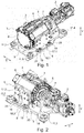
- Figs. 1 and 2 show a driving arrangement 1 for a construction machine according to an embodiment of the present invention in different perspective views.
- the construction machine is an excavator comprising an undercarriage and a superstructure, which is pivotably with respect to the undercarriage.
- On the superstructure of the excavator an operator's cabin and a boom with a working equipment at its distal end are provided.
- the excavator may be a pure electric excavator, implying that the locomotion of the excavator, the actuation of the boom and the actuation of the swing drive between the undercarriage and the superstructure are powered by electrical energy only.
- the electrical energy for powering those devices may be stored in multiple battery modules provided on top of the excavator's superstructure, wherein said battery modules may function as the excavator's counterweight.
- the excavator may comprise one or multiple electric motors for powering tracks provided at the excavator's undercarriage to move the excavator backwards, forwards and sidewards.
- the excavator may comprise an additional electric motor for powering the excavator's swing drive.
- the driving arrangement 1 of the present embodiment comprises a hydraulic pump 2 for powering multiple hydraulic cylinders of the excavator's boom via a hydraulic circuit.
- the excavator comprises a boom with multiple arms, which are movable with respect to each other via hydraulic cylinders.
- the hydraulic cylinders are part of a hydraulic circuit, which is powered by the hydraulic pump 2 of the driving arrangement 1 of the present embodiment.
- the driving arrangement 1 comprises an electric motor 3, which is powered by electric energy of the excavator's battery modules.
- the electric motor 3 comprises a lateral surface 4, a front surface 5 and a back surface 6, wherein the motor's shaft is oriented symmetrically with respect to the lateral surface 4 and is accessible via the front surface 5.
- the driving arrangement 1 comprises a connection means 7, which is configured as an elastic coupling in the present embodiment.
- the connection means 7 is provided between the electric motor 3 and the hydraulic pump 2 for transferring power of the electric motor 3 to the hydraulic pump 2.
- the driving arrangement 1 comprises a supporting device 8 for mounting the driving arrangement 1 to the construction machine.
- the supporting device 8 is configured to support the electric motor 3 and the hydraulic pump 2 as well as the connection means 7.
- the supporting device 8 comprises a base element 9, which is illustrated in Fig. 3 .
- the base element 9 exhibits a substantially rectangular plate-like base portion 10 via which the driving arrangement 1 can be mounted to the construction machine.
- the base portion 10 comprises a damping device with four damping units 11.1, 11.2, 11.3, 11.4, which are shown in Figs. 1 and 2 , via which the driving arrangement 1 can be mounted to the construction machine.
- the damping units 11.1, 11.2, 11.3, 11.4 are configured as mechanical damping units, e.g.
- the base portion 10 is oriented horizontally when the driving arrangement 1 is attached to the construction machine in the intended fashion.
- the base element 9 comprises a vertical plate-like pump mounting portion 12, which is provided upright on and in parallel to the short narrow side surfaces of the rectangular plate-like base portion 10.
- the pump mounting portion 12 is formed symmetrically and exhibits a through-hole 13, which is provided substantially centrally.
- the pump mounting portion 12 is situated offset and in proximity to one of the short narrow side surfaces of the base portion 10.
- the base element 9 comprises a first strengthening portion 14.1 and a second strengthening portion 14.2, which respectively extend in parallel to the long narrow side surfaces of the base portion 10, are formed plate-like, and are provided upright in a vertical fashion on the base portion 10.
- the strengthening portions 14.1 and 14.2 extend approximately along the entire length of the base portion 10 and engage with the pump mounting portion 12.
- the pump mounting portion 12 and the strengthening portions 14.1, 14.2 are welded to each other, wherein all three parts are also respectively welded to the base portion 10.
- the strengthening portions 14.1, 14.2 serve as strengthening means for strengthening the connection between the pump mounting portion 12 and the base portion 10, thereby fixing the positional relationship between both parts.
- the entire base element 9 is made from steel.
- the hydraulic pump 2 is connected to a mounting surface 16 of the pump mounting portion 12, which is facing away from the base portion 10.
- the hydraulic pump 2 is attached to the pump mounting portion 12 with multiple bolts and/or screws, as shown in Fig. 2 , for fixing the positional relationship between the base element 9 and the hydraulic pump 2.
- the connection means 7, which is coupled with the shaft of the hydraulic pump 2 is fixed in the through-hole 13 of the pump mounting portion 12.
- the electric motor 3 is positioned above the base portion 10 and between the strengthening sections 14.1, 14.2 of the base element 9.
- the base portion 10 exhibits a cut-out 15 between the damping units 11.3, 11.4 provided on the mounting surface 16 side of the mounting portion 12 for allowing good accessibility to the hydraulic pump 2. Further, as derivable from Fig. 3 , the base portion 10 exhibits a central cut-out 30 for accommodating the bottom portion of the electric motor 3, thereby allowing for a compact design of the driving arrangement 1.
- the driving arrangement 1 comprises an adjustment mechanism for adjusting the positional relationship between the electric motor 3 and the base portion 10 of the base element 9.
- the adjustment mechanism of the present embodiment is configured to adjust the positional relationship between those two parts in vertical direction V and in depth direction T of the driving arrangement 1.
- the connection means 7 and the hydraulic pump 2 are provided stationary with respect to the base portion 10 of the base element 9, the adjustment mechanism allows for an adjustment of the positional relationship between the electric motor 3 and the hydraulic pump 2 in vertical direction V and in depth direction T.
- the adjustment mechanism is embodied by the supporting device 8.
- the supporting device 8 comprises two plate-like mounting portions 17.1, 17.2, which are provided upright and in vertical fashion on the base portion 10.
- the mounting portion 17.1, 17.2 are attached to the right and left sides of the lateral surface 4 of the electric motor 3 via multiple bolts and/or screws, as shown in Fig. 4 .
- the mounting portion 17.1, 17.2 are oriented in parallel to the strengthening portions 14.1, 14.2 of the base element 9.
- the mounting portions 17.1, 17.2 are respectively provided outside of the strengthening portions 14.1, 14.2, as shown in Fig. 4 .
- the mounting portions 17.1, 17.2 respectively exhibit a plate-like lip portion 18.1, 18.2, which is oriented perpendicular to the remaining mounting portions 17.1, 17.2 such that the entire mounting portions 17.1, 17.2 exhibit a substantially L-shaped cross section.
- the lip portions 18.1, 18.2 are provided horizontally and parallel to the base portion 10 of the base element 9.
- each lip portion 18.1, 18.2 is connected to the base portion 8 via two vertical adjustment screws 19.
- the vertical adjustment screws 19 exhibit a hexagonal head 20 for turning of the screw and a cylindrical portion 21 with an outer thread.
- the vertical adjustment screws 19 exhibit a planar engagement surface 22.
- the planar engagement surface 22 of the vertical adjustment screws 19 engages with the top surface of the base portion 10 to form a planar contact.
- the outer thread of the cylindrical portion 21 of the vertical adjustment screws 19 engages with an inner thread formed in the respective lip portion 18.1, 18.2 of the mounting portions 17.1, 17.2.
- the outer thread 21 is turned relatively to the inner thread of the lip portion 18.1, 18.2, thereby moving the lip portion 18.1, 18.2 in vertical direction V with respect to the base portion 10, as the front surface 22 of the vertical adjustment screw 19 is in planar engagement with the base portion 10.
- the electric motor 3 is mounted to the lip portions 18.1, 18.2 via the mounting portions 17.1, 17.2, turning of the vertical adjustments screws 19 displaces the electric motor 3 with respect to the base portion 10 and therefore with respect to the hydraulic pump 2 in vertical direction V.
- the mounting portions 17.1, 17.2 are respectively connected to the strengthening portions 14.1, 14.2 of the base element 9 with two horizontal adjustment screws 25.
- the mounting portions 17.1, 17.2 and therefore the electric motor 3 may moved with respect to the base portion 10 and thus with respect to the hydraulic pump 2 in depth direction T.
Landscapes
- Engineering & Computer Science (AREA)
- Mining & Mineral Resources (AREA)
- Civil Engineering (AREA)
- General Engineering & Computer Science (AREA)
- Structural Engineering (AREA)
- Mechanical Engineering (AREA)
- Details Of Reciprocating Pumps (AREA)
- Operation Control Of Excavators (AREA)
Applications Claiming Priority (1)
| Application Number | Priority Date | Filing Date | Title |
|---|---|---|---|
| PCT/CN2019/104136 WO2021042256A1 (en) | 2019-09-03 | 2019-09-03 | Driving arrangement for construction machine |
Publications (1)
| Publication Number | Publication Date |
|---|---|
| EP3789544A1 true EP3789544A1 (de) | 2021-03-10 |
Family
ID=72234756
Family Applications (1)
| Application Number | Title | Priority Date | Filing Date |
|---|---|---|---|
| EP20192463.6A Withdrawn EP3789544A1 (de) | 2019-09-03 | 2020-08-24 | Antriebsanordnung für baumaschine |
Country Status (4)
| Country | Link |
|---|---|
| US (1) | US20210062458A1 (de) |
| EP (1) | EP3789544A1 (de) |
| CN (1) | CN112443007B (de) |
| WO (1) | WO2021042256A1 (de) |
Families Citing this family (1)
| Publication number | Priority date | Publication date | Assignee | Title |
|---|---|---|---|---|
| WO2023190179A1 (ja) * | 2022-03-31 | 2023-10-05 | 株式会社クボタ | 旋回作業機 |
Citations (6)
| Publication number | Priority date | Publication date | Assignee | Title |
|---|---|---|---|---|
| CA936439A (en) * | 1970-02-23 | 1973-11-06 | Takagi Moriyuki | Hydraulic driving device |
| US4962825A (en) * | 1987-08-21 | 1990-10-16 | Clark Equipment Company | Skid steer loader |
| KR20100073508A (ko) * | 2008-12-23 | 2010-07-01 | 두산인프라코어 주식회사 | 하이브리드 건설기계의 동력전달장치 |
| EP2302139A2 (de) * | 2009-09-29 | 2011-03-30 | Kobelco Construction Machinery Co., Ltd. | Hybride Baumaschine |
| CN104963375A (zh) | 2015-06-30 | 2015-10-07 | 泰安嘉和重工机械有限公司 | 用于液压挖掘机的双动力装置 |
| EP3696331A1 (de) * | 2019-02-15 | 2020-08-19 | Guangxi LiuGong Machinery Co., Ltd. | Baumaschine mit schwungradanordnung |
Family Cites Families (17)
| Publication number | Priority date | Publication date | Assignee | Title |
|---|---|---|---|---|
| FR2541661B1 (fr) * | 1983-02-24 | 1986-01-31 | Ppm Sa | Ensemble de stabilisation pour engin mobile |
| US8037963B2 (en) * | 2006-08-02 | 2011-10-18 | Komatsu Ltd. | Hybrid working vehicle |
| CN201294417Y (zh) * | 2008-10-13 | 2009-08-19 | 中山力劲机械有限公司 | 油泵专用电机 |
| JP5079738B2 (ja) * | 2009-05-15 | 2012-11-21 | 日立建機株式会社 | 建設機械 |
| CN101736765B (zh) * | 2009-12-10 | 2011-09-14 | 同济大学 | 一种基于全液压传动的履带推土机 |
| JP5054851B2 (ja) * | 2010-02-22 | 2012-10-24 | 日立建機株式会社 | 電動式建設機械 |
| JP5247848B2 (ja) * | 2011-03-31 | 2013-07-24 | 株式会社小松製作所 | 建設機械 |
| JP6006512B2 (ja) * | 2012-03-23 | 2016-10-12 | Kyb株式会社 | 駆動ユニット |
| WO2013154218A1 (ko) * | 2012-04-13 | 2013-10-17 | 볼보 컨스트럭션 이큅먼트 에이비 | 하이브리드형 건설기계 |
| CN202608539U (zh) * | 2012-06-27 | 2012-12-19 | 中联重科股份有限公司渭南分公司 | 动力系统的安装结构和液压挖掘机 |
| CN204781069U (zh) * | 2015-06-18 | 2015-11-18 | 上海彭浦机器厂有限公司 | 一种用于履带式挖掘机驱动电机与液压泵的联接装置 |
| CN204827837U (zh) * | 2015-08-13 | 2015-12-02 | 北京中金泰达电液科技有限公司 | 液压系统可调节同轴度的电机油泵组合装置 |
| CN105672395A (zh) * | 2016-03-24 | 2016-06-15 | 徐州徐工特种工程机械有限公司 | 一种辅助支撑系统 |
| JP2018165491A (ja) * | 2017-03-28 | 2018-10-25 | 株式会社荏原製作所 | 横軸ポンプ及び横軸ポンプ用ベース |
| CN207473417U (zh) * | 2017-12-12 | 2018-06-08 | 中国长江电力股份有限公司 | 一种同轴度调整装置 |
| CN208472807U (zh) * | 2018-05-28 | 2019-02-05 | 宋晓林 | 一种使用动力电池驱动的小型液压挖掘机 |
| CN209170124U (zh) * | 2018-11-14 | 2019-07-26 | 南京腾图节能科技有限公司 | 一种环形电机支架 |
-
2019
- 2019-09-03 WO PCT/CN2019/104136 patent/WO2021042256A1/en not_active Ceased
-
2020
- 2020-07-29 US US16/941,715 patent/US20210062458A1/en not_active Abandoned
- 2020-08-24 EP EP20192463.6A patent/EP3789544A1/de not_active Withdrawn
- 2020-09-02 CN CN202010908999.5A patent/CN112443007B/zh active Active
Patent Citations (6)
| Publication number | Priority date | Publication date | Assignee | Title |
|---|---|---|---|---|
| CA936439A (en) * | 1970-02-23 | 1973-11-06 | Takagi Moriyuki | Hydraulic driving device |
| US4962825A (en) * | 1987-08-21 | 1990-10-16 | Clark Equipment Company | Skid steer loader |
| KR20100073508A (ko) * | 2008-12-23 | 2010-07-01 | 두산인프라코어 주식회사 | 하이브리드 건설기계의 동력전달장치 |
| EP2302139A2 (de) * | 2009-09-29 | 2011-03-30 | Kobelco Construction Machinery Co., Ltd. | Hybride Baumaschine |
| CN104963375A (zh) | 2015-06-30 | 2015-10-07 | 泰安嘉和重工机械有限公司 | 用于液压挖掘机的双动力装置 |
| EP3696331A1 (de) * | 2019-02-15 | 2020-08-19 | Guangxi LiuGong Machinery Co., Ltd. | Baumaschine mit schwungradanordnung |
Also Published As
| Publication number | Publication date |
|---|---|
| US20210062458A1 (en) | 2021-03-04 |
| WO2021042256A1 (en) | 2021-03-11 |
| CN112443007B (zh) | 2022-09-13 |
| CN112443007A (zh) | 2021-03-05 |
Similar Documents
| Publication | Publication Date | Title |
|---|---|---|
| US9790662B2 (en) | Hybrid-type working machine | |
| JP7393323B2 (ja) | 建設機械 | |
| US20210066688A1 (en) | Energy Storage Assembly | |
| EP3789545A1 (de) | Antriebsanordnung für baumaschine | |
| EP3789544A1 (de) | Antriebsanordnung für baumaschine | |
| US12565753B2 (en) | Construction machine | |
| US12366049B2 (en) | Swivel working machine | |
| CN111246711A (zh) | 冷却设备、电子装置以及车辆 | |
| JP2008044408A (ja) | バッテリ駆動式建設機械のバッテリ保持構造 | |
| KR20230083226A (ko) | 전동식 작업 기계 | |
| JP5306786B2 (ja) | サーボ制御システム及び作業機械 | |
| JP2015142472A (ja) | ブスバー構造体、電力変換装置、作業機械 | |
| JP6444038B2 (ja) | ショベル | |
| US20230339305A1 (en) | Electric Work Machine | |
| US20260027945A1 (en) | Handling machine | |
| CN218301064U (zh) | 一种可调节电机固定支架 | |
| JP2020057547A (ja) | 電気機器 | |
| CN216920097U (zh) | 一种一体化超速抓拍警示杆 | |
| JP2024055444A (ja) | バッテリ保持構造および建設機械 | |
| US20240399846A1 (en) | Engine-driven-dc-supply unit | |
| JP2021035121A (ja) | 電力制御装置 | |
| JP6385069B2 (ja) | ショベル | |
| GB2631275A (en) | Power module for work machine | |
| KR20250110256A (ko) | 모듈형 액추에이터 제어 베이스 장착 시스템 | |
| EP3806125B1 (de) | Betriebsmechanismus für eine hochspannungsschaltvorrichtung |
Legal Events
| Date | Code | Title | Description |
|---|---|---|---|
| PUAI | Public reference made under article 153(3) epc to a published international application that has entered the european phase |
Free format text: ORIGINAL CODE: 0009012 |
|
| STAA | Information on the status of an ep patent application or granted ep patent |
Free format text: STATUS: THE APPLICATION HAS BEEN PUBLISHED |
|
| AK | Designated contracting states |
Kind code of ref document: A1 Designated state(s): AL AT BE BG CH CY CZ DE DK EE ES FI FR GB GR HR HU IE IS IT LI LT LU LV MC MK MT NL NO PL PT RO RS SE SI SK SM TR |
|
| AX | Request for extension of the european patent |
Extension state: BA ME |
|
| STAA | Information on the status of an ep patent application or granted ep patent |
Free format text: STATUS: THE APPLICATION IS DEEMED TO BE WITHDRAWN |
|
| 18D | Application deemed to be withdrawn |
Effective date: 20210911 |