EP3789072B1 - Führungsdraht - Google Patents
Führungsdraht Download PDFInfo
- Publication number
- EP3789072B1 EP3789072B1 EP18917477.4A EP18917477A EP3789072B1 EP 3789072 B1 EP3789072 B1 EP 3789072B1 EP 18917477 A EP18917477 A EP 18917477A EP 3789072 B1 EP3789072 B1 EP 3789072B1
- Authority
- EP
- European Patent Office
- Prior art keywords
- coil body
- guide wire
- core shaft
- resin layer
- protruding portion
- Prior art date
- Legal status (The legal status is an assumption and is not a legal conclusion. Google has not performed a legal analysis and makes no representation as to the accuracy of the status listed.)
- Active
Links
Images


Classifications
-
- A—HUMAN NECESSITIES
- A61—MEDICAL OR VETERINARY SCIENCE; HYGIENE
- A61M—DEVICES FOR INTRODUCING MEDIA INTO, OR ONTO, THE BODY; DEVICES FOR TRANSDUCING BODY MEDIA OR FOR TAKING MEDIA FROM THE BODY; DEVICES FOR PRODUCING OR ENDING SLEEP OR STUPOR
- A61M25/00—Catheters; Hollow probes
- A61M25/01—Introducing, guiding, advancing, emplacing or holding catheters
- A61M25/09—Guide wires
- A61M25/09016—Guide wires with mandrils
-
- A—HUMAN NECESSITIES
- A61—MEDICAL OR VETERINARY SCIENCE; HYGIENE
- A61M—DEVICES FOR INTRODUCING MEDIA INTO, OR ONTO, THE BODY; DEVICES FOR TRANSDUCING BODY MEDIA OR FOR TAKING MEDIA FROM THE BODY; DEVICES FOR PRODUCING OR ENDING SLEEP OR STUPOR
- A61M25/00—Catheters; Hollow probes
- A61M25/01—Introducing, guiding, advancing, emplacing or holding catheters
- A61M25/09—Guide wires
- A61M2025/09058—Basic structures of guide wires
- A61M2025/09083—Basic structures of guide wires having a coil around a core
- A61M2025/09091—Basic structures of guide wires having a coil around a core where a sheath surrounds the coil at the distal part
-
- A—HUMAN NECESSITIES
- A61—MEDICAL OR VETERINARY SCIENCE; HYGIENE
- A61M—DEVICES FOR INTRODUCING MEDIA INTO, OR ONTO, THE BODY; DEVICES FOR TRANSDUCING BODY MEDIA OR FOR TAKING MEDIA FROM THE BODY; DEVICES FOR PRODUCING OR ENDING SLEEP OR STUPOR
- A61M25/00—Catheters; Hollow probes
- A61M25/01—Introducing, guiding, advancing, emplacing or holding catheters
- A61M25/09—Guide wires
- A61M2025/09133—Guide wires having specific material compositions or coatings; Materials with specific mechanical behaviours, e.g. stiffness, strength to transmit torque
-
- A—HUMAN NECESSITIES
- A61—MEDICAL OR VETERINARY SCIENCE; HYGIENE
- A61M—DEVICES FOR INTRODUCING MEDIA INTO, OR ONTO, THE BODY; DEVICES FOR TRANSDUCING BODY MEDIA OR FOR TAKING MEDIA FROM THE BODY; DEVICES FOR PRODUCING OR ENDING SLEEP OR STUPOR
- A61M25/00—Catheters; Hollow probes
- A61M25/01—Introducing, guiding, advancing, emplacing or holding catheters
- A61M25/09—Guide wires
- A61M2025/09191—Guide wires made of twisted wires
Definitions
- the disclosed embodiment relates to a guide wire.
- a guide wire used for inserting a catheter into a blood vessel, a digestive organ, or the like typically includes a core shaft using a wire material, and a coil body wound around an outer periphery of the core shaft, and a distal end of the core shaft and a distal end of the coil body are joined.
- a technique is known in which a resin layer is formed on the coil body for the purpose of improving slidability by smoothing the guide wire, thrombus adhesion preventing property, operability, and the like.
- Patent Literatures 1, 2 and 3 disclose a guide wire in which a resin coating (resin layer) is formed on an outer periphery of a coil body.
- the guide wire described in Patent Literature 1 has a problem that a resin layer is formed between a coil body and a core shaft without a gap, and thus, the flexibility of the guide wire is not sufficient.
- the guide wire described in Patent Literature 2 has a problem that a resin layer may be peeled or damaged when a guide wire is curved. Specifically, when the guide wire is curved, a space between adjacent wires of a coil body expands at an outer side of the curve. In the guide wire described in Patent Literature 2, the resin layer is formed on an outer peripheral surface of the coil body, and thus, the thickness of the resin layer is reduced by the resin layer being elongated in a gap expanded between two adjacent lines of a wire, which may lead to peeling or damage of the resin layer.
- the invention has been made to resolve the above-described problems, and an object thereof is to provide a technique of suppressing peeling and damage of a resin layer while flexibility is secured in a guide wire including a coil body and a resin layer.
- the invention is defined by the subject matter of the independent claim. Further aspects are disclosed in the subclaims. The invention has been made to resolve at least a part of the above-described problems, and can be implemented as the following aspects.
- the guide wire when the guide wire is curved, a wire forming a coil body moves with the curve to decrease (reduce) or enlarge (expand) a space between the adjacent wires.
- the guide wire includes the resin layer extending toward the core shaft relative to the inner peripheral surface of the coil body, and thus, the thickness of the resin layer in a gap expanded with the curve of the guide wire between the adjacent wires, can be kept thick as compared to, for example, a configuration in which the resin layer is formed only on the outer peripheral surface of the coil body. Therefore, with this configuration, it is possible to suppress peeling and damage of the resin layer between the adjacent wires when the guide wire is curved.
- the protruding portion contacts the core shaft.
- the resin layer contacts the core shaft, and thus, the thickness of the resin layer in a gap expanded with the curve of the guide wire between the adjacent wires, can be kept much thicker.
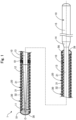
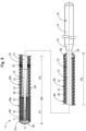
- Fig. 1 is a schematic partial cross-sectional view illustrating an entire configuration of a guide wire 1 according to a first example.
- the guide wire 1 is a medical device used when a catheter is inserted into a blood vessel or a digestive organ, and includes a core shaft 10, a coil body 20, a resin layer 30, a distal end joint part 51, a proximal end joint part 56, and an intermediate fixing part 61.
- an axis passing through the center of the guide wire 1 is represented by an axis O (dash-dot-dash line).
- the left side in Fig. 1 is referred to as a "distal end side" of the guide wire 1 and components, and the right side in Fig. 1 is referred to as a "proximal end side” of the guide wire 1 and components.
- an end part located on the distal end side is referred to as a "distal end part” or simply a “distal end”
- an end part located on the proximal end side is referred to as a "proximal end part” or simply a "proximal end” .
- the distal end side corresponds to a "distal side”
- the proximal end side corresponds to a "proximal side.”
- the core shaft 10 is a tapered long member having a large diameter at the proximal end side and a small diameter at the distal end side.
- the core shaft 10 may be formed of a material such as a stainless alloy (SUS304, SUS316, etc.), a superelastic alloy such as an Ni-Ti alloy, a piano wire, a nickel-chromium base alloy, a cobalt alloy, and tungsten.
- the core shaft 10 may be formed of a known material other than the above.
- the core shaft 10 includes a small-diameter part 11, a first tapered part 12, a first large-diameter part 13, a second tapered part 14, and a second large-diameter part 15 in this order from the distal end side to the proximal end side.
- An outer diameter and length at a portion of the core shaft 10 may be optionally determined.
- the small-diameter part 11 is formed at the distal end part of the core shaft 10.
- the small-diameter part 11 is a part where the outer diameter of the core shaft 10 is smallest, and has a substantially cylindrical shape having a constant outer diameter.
- the distal end joint part 51 is formed at the distal end part of the small-diameter part 11.
- the first tapered part 12 is formed between the small-diameter part 11 and the first large-diameter part 13.
- the first tapered part 12 has a tapered shape whose outer diameter increases from the distal end side toward the proximal end side.
- the first large-diameter part 13 is formed between the first tapered part 12 and the second tapered part 14.
- the first large-diameter part 13 has a substantially cylindrical shape having a constant outer diameter larger than the outer diameter of the small-diameter part 11.
- the proximal end joint part 56 is formed at the proximal end part of the first large-diameter part 13. Outer peripheral surfaces of the small-diameter part 11, the first tapered part 12, and the first large-diameter part 13 are covered by the coil body 20 described later.
- the second tapered part 14 is formed between the first large-diameter part 13 and the second large-diameter part 15.
- the second tapered part 14 has a tapered shape whose outer diameter increases from the distal end side toward the proximal end side.
- the second large-diameter part 15 is formed at the proximal end part of the core shaft 10.
- the second large-diameter part 15 is a portion where the outer diameter of the core shaft 10 is largest, and has a substantially cylindrical shape having a constant outer diameter.
- the second tapered part 14 and the second large-diameter part 15 are not covered by the coil body 20, and are used when an operator grasps the guide wire 1.
- the coil body 20 has a substantially hollow cylindrical shape in which a wire 21 is spirally wound around the core shaft 10.
- the coil body 20 of the present embodiment is arranged to cover the outer peripheral surfaces of the small-diameter part 11, the first tapered part 12, and the first large-diameter part 13 of the core shaft 10, and is not arranged on the second tapered part 14 and the second large-diameter part 15 of the core shaft 10.
- the wire 21 forming the coil body 20 may be a solid wire composed of one wire or a strand obtained by twisting a plurality of wires. If the wire 21 is a solid wire, the coil body 20 is configured as a single coil, and if the wire 21 is a strand, the coil body 20 is configured as a hollow stranded coil.
- the coil body 20 may be configured by combining a single coil and a hollow stranded coil.
- a wire diameter of the wire 21 and an average coil diameter in the coil body 20 may be optionally determined.
- the wire 21 may be formed of, for example, a stainless alloy (SUS304, SUS316, etc.), a superelastic alloy such as an Ni-Ti alloy, a piano wire, a nickel-chromium base alloy, a cobalt alloy, a radiolucent alloy such as tungsten, gold, platinum, tungsten, and a radiopaque alloy such as an alloy containing these elements (for example, a platinum-nickel alloy).
- the wire 21 may be formed of a known material other than the above.
- the coil body 20 is fixed to the core shaft 10 by the distal end joint part 51, the proximal end joint part 56, and the intermediate fixing part 61.
- the distal end joint part 51 is a member that joins a distal end part of the coil body 20 and the distal end part of the small-diameter part 11 of the core shaft 10.
- the distal end joint part 51 is formed of metal solder such as silver solder, gold solder, zinc, an Sn-Ag alloy, and an Au-Sn alloy.
- the distal end of the coil body 20 and the distal end of the small-diameter part 11 are fixed by the metal solder.
- the distal end joint part 51 may be formed by an adhesive such as an epoxy-based adhesive.
- the proximal end joint part 56 is a member that joins a proximal end part of the coil body 20 and the proximal end part of the first large-diameter part 13 of the core shaft 10.
- the proximal end joint part 56 may be formed of a material that is same as the material of the distal end joint part 51, or may be formed of a material that is different from the material of the distal end joint part 51.
- the intermediate fixing part 61 is a member that fixes the coil body 20 and the first large-diameter part 13 of the core shaft 10, in the vicinity of an intermediate portion of the coil body 20 in an axis O direction.
- the intermediate fixing part 61 may be formed of a material that is same as the materials of the distal end joint part 51 and the proximal end joint part 56, or may be formed of a material that is different from the materials of the distal end joint part 51 and the proximal end joint part 56.
- the guide wire 1 may include a plurality of fixing parts for fixing the coil body 20 and the core shaft 10.
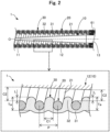
- Fig. 2 is a partial enlarged view of the guide wire 1.
- the upper side in Fig. 2 illustrates a portion of the guide wire 1, from the small-diameter part 11 to the first large-diameter part 13.
- the lower side in Fig. 2 illustrates an enlarged view of a portion surrounded by a broken-line rectangle in the upper side.
- the left side in Fig. 2 corresponds to the distal end side (distal side) of the guide wire 1 and components
- the right side in Fig. 2 corresponds to the proximal end side (proximal side) of the guide wire 1 and components.
- gaps C1 are formed between the adjacent wires 21 over an entire region in the axis O direction ( Fig. 1 and the lower side in Fig. 2 ).
- a gap C1 is defined as a size (length) at a portion where a distance between the adjacent wires 21 is closest in any cross section in the axis O direction.
- the size of the gap C1 may be optionally determined.
- the gaps C1 formed between the adjacent wires 21 have a constant size equal to the wire diameter of the wire 21. All the gaps C1 may have the same size, at least some of the gaps C1 may have different sizes, or all of the gaps C1 may have different sizes.
- the coil body 20 includes the sparsely wound part over the entire region in the axis O direction.
- a void C2 is formed between the outer peripheral surface of the core shaft 10 and an inner peripheral surface of the wire 21 of the coil body 20 (that is, an inner peripheral surface (inner surface) of the coil body 20) over the entire region in the axis O direction ( Fig. 1 and the lower side in Fig. 2 ).
- the void C2 is defined as a size (length) at a portion where a distance between the inner peripheral surface of the wire 21 and the outer peripheral surface of the core shaft 10 is closest in any cross section in the axis O direction.
- the size of the void C2 may be optionally determined.
- the inner diameter of the coil body 20 is constant while the outer diameter of the core shaft 10 increases from the distal end side toward the proximal end side.
- the void C2 formed between the inner peripheral surfaces of the wire 21 and the outer peripheral surface of the core shaft 10 is gradually smaller from the distal end side to the proximal end side.
- the resin layer 30 is a layer of resins that cover at least the outer peripheral surface (outer surface) of the coil body 20.
- the resin layer 30 may be formed of a resin material having hydrophobicity, a resin material having hydrophilicity, or a mixture thereof.
- the resin material having hydrophobicity to be employed include silicone resin, polyurethane, polyethylene, polyvinyl chloride, polyester, polypropylene, polyamide, polystyrene, polyolefin elastomer, polyester elastomer, polyamide elastomer, and polyurethane elastomer.
- the resin material having hydrophilicity to be employed examples include starch-based resin such as carboxymethyl starch, cellulose-based resin such as carboxymethylcellulose, polysaccharides such as alginic acid, chitin, chitosan, and hyaluronic acid, natural water-soluble polymer substances such as gelatin, and synthetic water-soluble polymer substances such as polyvinyl alcohol, polyethylene oxide, polyethylene glycol, polypropylene glycol, polyvinylpyrrolidone, and water-soluble nylon.
- starch-based resin such as carboxymethyl starch
- cellulose-based resin such as carboxymethylcellulose
- polysaccharides such as alginic acid, chitin, chitosan, and hyaluronic acid
- natural water-soluble polymer substances such as gelatin
- synthetic water-soluble polymer substances such as polyvinyl alcohol, polyethylene oxide, polyethylene glycol, polypropylene glycol, polyvinylpyrrolidone, and water-soluble nylon.
- the resin layer 30 includes a surface layer 31, protruding portions 32, a distal end resin layer 38, and a proximal end resin layer 39.
- the surface layer 31 is a part of the resin layer 30 and is a layered portion that covers the outer peripheral surface of the coil body 20.
- the shape of the surface layer 31 in the cross section illustrated in Fig. 2 is a wave shape.
- the thickness of the surface layer 31 may be optionally determined.
- the distal end resin layer 38 is a part of the resin layer 30 and is a layered portion that covers an outer peripheral surface of the distal end joint part 51.
- the proximal end resin layer 39 is a part of the resin layer 30 and is a layered portion that covers an outer peripheral surface of the proximal end joint part 56.
- Such a protruding portion 32 is a part of the resin layer 30 and is a portion protruding toward the core shaft 10 through the gap C1 between the adjacent wires 21 of the coil body 20.
- the protruding portion 32 extends toward the core shaft 10 relative to the inner peripheral surface of the coil body 20, in other words, a surface of the wire 21 on a side of the core shaft 10.
- the shape of a protrusion of the protruding portion 32 in the cross section illustrated in Fig. 2 is an arc shape.
- a protruding length L of the protruding portion 32 is defined as a length between the surface of the wire 21 on the side of the core shaft 10 and a protrusion distal end of the protruding portion 32 (a portion closest to the core shaft 10) in any cross section in the axis O direction.
- the protruding length L may be optionally determined.
- the protruding lengths L of the protruding portions 32 formed between the adjacent wires 21 are constant (same length) and are set to about half of the wire diameter of the wire 21. At least some or all of the protruding lengths L of the protruding portions 32 may be different from each other.
- a thickness Ta of the resin layer 30 is defined as a thickness (length) of the resin layer 30 in a middle part between the adjacent wires 21 in any cross section in the axis O direction.
- the thickness Ta of the resin layer 30 between the adjacent wires 21 is constant (same thickness) and is set to about 1.5 times to about 2 times the wire diameter of the wire 21.
- all of the protruding portions 32 included in the resin layer 30 and the core shaft 10 are separated and not in contact.
- the thickness of the resin layer 30 may be optionally determined, and at least some or the thickness of the resin layer 30 at all or some portions may be different from each other.
- the resin layer 30 may be formed, for example, by applying a liquidized resin material to the outer peripheral surface of the coil body 20.
- the surface layer 31 is formed through the solidification of the resin material that adheres to the outer peripheral surface of the coil body 20.
- the protruding portion 32 is formed through the solidification of the resin material dropped toward the core shaft 10 from the gaps C1 between the adjacent wires 21 of the coil body 20.
- the resin layer 30 can be easily formed.
- the surface layer 31 and the protruding portion 32 are formed integrally, but the surface layer 31 and the protruding portion 32 may be formed separately.
- the protruding portions 32 may be formed by applying a liquidized resin material, and then the surface layer 31 may be formed by winding a thin film-like resin material around the outer peripheral surface of the coil body 20. If the surface layer 31 and the protruding portion 32 are formed separately, the surface layer 31 and the protruding portion 32 may be formed by using different resin materials. In addition, an extruder may be used to extrude a resin material, and then the extruded resin material may pass through the gaps C1 to form the protruding portion 32.
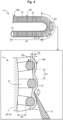
- Fig. 3 is a diagram for explaining the resin layer 30 when the guide wire 1 is curved.
- the upper side in Fig. 3 illustrates a schematic diagram representing a portion at the distal end side of the curved guide wire 1.
- the lower side in Fig. 3 illustrates an enlarged view of a portion surrounded by a broken-line rectangle in the upper side.
- the wire 21 forming the coil body 20 moves with the curve to decrease (reduce) or enlarge (expand) a space P between the adjacent wires 21.
- the gap C1 between the adjacent wires 21 is as described with reference to Figs. 1 and 2 .
- the space P between the adjacent wires 21 changes with the curve to cause clogging or enlargement between the adjacent wires 21.
- the gap C1 between the adjacent wires 21 on an outer side of a curved part increases, and the gap C1 between the adjacent wires 21 on an inner side of the curved part decreases.
- the guide wire 1 includes the resin layer 30 (protruding portion 32) extending toward the core shaft 10 relative to the inner peripheral surface of the coil body 20.
- the resin layer 30 is elongated, resulting in that the thickness of the resin layer 30 becomes thinner from a "thickness Ta during a normal time" to a "thickness Tb while being elongated", the thickness Tb of the resin layer 30 at the gap C1 expanded between the adjacent wires 21 can be kept thick.
- an additional device 2 a device such as a catheter used together with the guide wire 1
- a force is applied in a direction in which the resin layer 30 is peeled off from the coil body 20 (lower side in Fig. 3 : white arrow)
- resistance to the peeling force (lower side in Fig. 3 : arrow with oblique hatching) can be obtained. Consequently, in the guide wire 1 according to the present embodiment, it is possible to suppress peeling and damage of the resin layer 30 between the adjacent wires 21 when the guide wire 1 is curved.
- the guide wire 1 according to the present example includes the resin layer 30 (protruding portion 32) extending toward the core shaft 10 relative to the inner peripheral surface of the coil body 20. Therefore, for example, even if the core shaft 10 is bent inside the coil body 20 when the guide wire 1 is used, the core shaft 10 comes into contact with the protruding portion 32 of the resin layer 30, and thus, is prevented from contacting with the coil body 20.
- the resin layer 30 (protruding portion 32) is formed of a resin material having flexibility as described above. Thus, in the guide wire 1 according to the present embodiment, damage and deformation of the core shaft 10 and the coil body 20 can be suppressed.
- the void C2 is formed between the coil body 20 and the core shaft 10. Therefore, the wire 21 forming the coil body 20 easily moves as compared to, for example, a configuration having no voids C2 such as a case where the resin layer 30 is formed between the coil body 20 and the core shaft 10 without a gap. As a result, in the guide wire 1 according to the present embodiment, it is possible to reduce power required to curve the guide wire 1 and improve the flexibility of the guide wire 1. Further, in the guide wire 1 according to the present embodiment, the void C2 is formed between the coil body 20 and the core shaft 10, and thus, the resin layer 30 can be easily formed as compared to a configuration having no voids C2.
- Fig. 4 is a diagram for explaining a resin layer 30x when a guide wire 1x in a comparative example is curved.
- the resin layer 30x is composed of only the surface layer 31 and does not include the protruding portion 32.
- the resin layer 30x is formed only on the outer peripheral surface of the coil body 20.
- the thickness Tb while being elongated of the resin layer 30x cannot be kept sufficiently thick, and thus, if, for example, the distal end of the additional device 2 is caught on a surface of the resin layer 30x, sufficient resistance cannot be obtained against the force (lower side in Fig. 4 : white arrow) in a direction in which the resin layer 30x is peeled off from the coil body 20.
- the resin layer 30x between the adjacent wires 21 may be peeled or damaged when the guide wire 1x is curved.
- the guide wire 1x in the comparative example does not include the protruding portion 32 ( Figs. 2 and 3 ) extending toward the core shaft 10 relative to the inner peripheral surface of the coil body 20, and thus, if the core shaft 10 is bent inside the coil body 20, the core shaft 10 may come into contact with the coil body 20 to cause damage or deformation of the core shaft 10 and the coil body 20.
- Fig. 5 is a partial enlarged view of a guide wire 1a according to an embodiment of the invention.
- a resin layer 30a includes protruding portions 32a.
- Such a protruding portion 32a is formed so that a protrusion distal end of the protruding portion 32a (a portion closest to the core shaft 10) comes into contact with the core shaft 10.
- the shape of a protrusion of the protruding portion 32a in the cross section illustrated in Fig. 5 is an elliptical arc shape.
- the protruding portion 32a may be formed by using a material and manufacturing method similar to those of the protruding portion 32 according to the first embodiment.
- the protruding length L of the protruding portion 32a in the guide wire 1a is equal to the size of the void C2 between the wire 21 and the core shaft 10.
- the thickness Ta of the resin layer 30a can be made thicker than that in the guide wire 1 according to the first embodiment. All of the protruding portions 32a included in the guide wire 1a may contact the core shaft 10, or at least some thereof may not contact the core shaft 10.
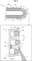
- Fig. 6 is a diagram for explaining the resin layer 30a when the guide wire 1a according to the embodiment of the invention above is curved.
- the guide wire 1a according to the second embodiment has the thickness Ta that is thick enough to cause the resin layer 30a (protruding portion 32a) to come into contact with the core shaft 10 ( Fig. 5 ).
- the thickness Tb while being elongated of the resin layer 30a at a gap expanded with the curve of the guide wire 1a between the adjacent wires 21, can be kept much thicker.
- the void C2 is formed between the coil body 20 and the core shaft 10.
- the wire 21 forming the coil body 20 easily moves, and thus, it is possible to reduce power required to curve the guide wire 1a and improve the flexibility of the guide wire 1a.
- the resin layer 30a can be easily formed as compared to a configuration having no voids C2.
- Fig. 7 is a partial enlarged view of a guide wire 1b according to a second embodiment of the invention.
- a resin layer 30b includes protruding portions 32b.
- a protrusion distal end of such a protruding portion 32b is joined to the core shaft 10.
- the shape of a protrusion of the protruding portion 32b in the cross section illustrated in Fig. 7 is a substantially rectangular shape in which a diameter of the center portion is reduced.
- the protruding portion 32b may be formed of a material similar to that of the protruding portion 32 according to the first example.
- the protruding portion 32b may be formed, for example, by applying an adhesive such as an epoxy-based adhesive to the outer peripheral surface of the core shaft 10 and then applying a liquidized resin material from the outer peripheral surface of the coil body 20. When the resin material is applied, the resin material is allowed to flow from the gap C1 of the coil body 20 to reach an adhesive layer of the core shaft 10. Thus, the protruding portion 32b joined to the core shaft 10 may be formed. Alternatively, fine irregularities may be provided on an outer surface of the core shaft 10, and then a molten resin material is poured toward the core shaft 10 and is physically joined to the core shaft 10 to form the protruding portion 32b.
- an adhesive such as an epoxy-based adhesive
- the protruding length L of the protruding portion 32b in the guide wire 1b is equal to the size of the void C2 between the wire 21 and the core shaft 10.
- the thickness Ta of the resin layer 30b can be made thicker than that in the guide wire 1 according to the first embodiment. All of the protruding portions 32b included in the guide wire 1b may be joined to the core shaft 10, or at least some thereof may not be joined to the core shaft 10.
- Fig. 8 is a diagram for explaining the resin layer 30b when the guide wire 1b according to the second embodiment of the invention. is curved.
- the resin layer 30b protruding portion 32b
- the thickness Tb while being elongated of the resin layer 30b at a gap expanded with the curve of the guide wire 1b, between the adjacent wires 21, can be made equal to the thickness Ta during a normal time (that is, the thickness Tb while being elongated can be kept much thicker).
- the void C2 is formed between the coil body 20 and the core shaft 10, and thus, as compared to a configuration having no voids C2, it is possible to improve the flexibility of the guide wire 1b and easily form the resin layer 30b.
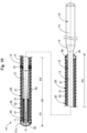
- Second Example Fig. 9 is a schematic partial cross-sectional view illustrating an entire configuration of a guide wire 1c according to a second example.
- a coil body 20c is formed, in a range P1 on the distal end side, as a closely wound part in which the adjacent wires 21 contact with each other without having the gap C1 ( Fig. 2 ), and is formed, in a range P2 on the proximal end side from the range P1, as a sparsely wound part in which there is the gap C1 between the adjacent wires 21.
- the guide wire 1c includes, at an inner side of the coil body 20c, an inner coil body 40 formed by spirally winding a wire 41 around the core shaft 10.
- the inner coil body 40 has a length shorter than a length of the coil body 20c in the axis O direction.
- a winding direction of the wire 41 in the inner coil body 40 is opposite to a winding direction in the coil body 20c.
- the winding direction of the wire 41 in the inner coil body may be the same as that in the coil body 20c, or may be a different direction other than the opposite direction.
- the wire 41 may be a solid wire or a strand.
- the inner coil body 40 may be configured by combining a single coil and a hollow stranded coil.
- a wire diameter of the wire 41 and an average coil diameter in the inner coil body 40 may be optionally determined.
- the wire 41 may be formed of a material similar to that of the wire 21 described in the first embodiment. The material used for the wire 41 may be the same as or different from that of the wire 21.
- the inner coil body 40 is fixed to the core shaft 10 by a distal end joint part 51c and an inner fixing part 62.
- the distal end joint part 51c joins a distal end part of the coil body 20c, a distal end part of the inner coil body 40, and the distal end part of the small-diameter part 11 of the core shaft 10.
- the distal end joint part 51c may be formed of a material similar to that of the distal end joint part 51 described in the first example.
- the material employed for the distal end joint part 51c may be the same as or different from that of the distal end joint part 51.
- the inner fixing part 62 joins a proximal end part of the inner coil body 40 and a part of the first tapered part 12 of the core shaft 10.
- the inner fixing part 62 may be formed of a material similar to that of the distal end joint part 51 described in the first embodiment.
- the material employed for the inner fixing part 62 may be the same as or different from that of the distal end joint
- a resin layer 30c includes the surface layer 31 and the protruding portion 32 in a portion (range P2) where the coil body 20c includes a sparsely wound part.
- the resin layer 30c includes only the surface layer 31 and does not include the protruding portion 32.
- the guide wire 1c may include, at a portion in the axis O direction, a closely wound part in which the adjacent wires 21 contact with each other without having the gap C1 ( Fig. 2 ).
- a range in which the closely wound part is formed may be optionally determined.
- the closely wound part is formed at the distal end part of the coil body 20c (guide wire 1c).
- the disclosed example is not limited to this, and the closely wound part may be formed at a rear end part of the coil body 20c (guide wire 1c).
- the sparsely wound part may be formed at the distal end part of the coil body 20c (guide wire 1c), and the inner coil body 40 may be arranged at an inner side of the sparsely wound part of the coil body 20c.
- the protruding portion 32 of the resin layer 30c may not be formed in the closely wound part of the coil body 20c.
- the guide wire 1c according to the second example can also exhibit a similar effect to that in the above-described first embodiment.
- the sparsely wound part formed with the resin layer 30c is located in a portion (range P2) where the coil body 20c does not cover the inner coil body 40, and thus, the movement of the inner coil body 40 cannot be prevented by the protruding portion 32 of the resin layer 30c.
- the flexibility of the guide wire 1c can be maintained even in the configuration including the inner coil body 40.
- Third Example Fig. 10 is a schematic partial cross-sectional view illustrating an entire configuration of a guide wire 1d according to a third example.
- the inner coil body 40 is provided at an inner side of the coil body 20, the entirety of which is formed as the sparsely wound part, in the range P1 on the distal end side.
- the inner coil body 40 has a length shorter than a length of the coil body 20 in the axis O direction.
- the configuration of the inner coil body 40 is similar to that of the second example.
- the inner coil body 40 is provided at the distal end part of the coil body 20 (guide wire 1d).
- the inner coil body 40 can be arranged at any position in the axis O direction.
- the inner coil body 40 may be arranged at a center part of the coil body 20 or may be arranged at a rear end part of the coil body 20.
- the sparsely wound part formed with the resin layer 30 may be located at a portion (range P1) where the coil body 20 covers the inner coil body 40.
- the guide wire 1d according to the fifth embodiment can also exhibit a similar effect to the above-described first embodiment and fourth embodiment.
- Fig. 11 is a partial enlarged view of a guide wire 1e according to a third embodiment.
- the left side in Fig. 11 corresponds to a distal end side (distal side) of the guide wire 1e and components
- the right side in Fig. 11 corresponds to a proximal end side (proximal side) of the guide wire 1e and components.
- a resin layer 30e includes protruding portions 32e and a resin film 34.
- the resin film 34 is a layer of resins that covers the outer peripheral surface (outer surface) of the core shaft 10.
- the resin film 34 may be formed of a material optionally selected from the resin materials listed for the resin layer 30 in the first embodiment.
- the resin film 34 may be formed, for example, by applying a liquidized resin material to the outer peripheral surface of the core shaft 10.
- the resin film 34 may be formed by joining a thin film-like resin material to the outer peripheral surface of the core shaft 10. For joining, for example, an adhesive such as an epoxy-based adhesive can be used.
- the thickness of the resin film 34 may be optionally determined.
- a protrusion distal end of such a protruding portion 32e is joined to the resin film 34.
- the shape of a protrusion of the protruding portion 32e in the cross section illustrated in Fig. 11 is a substantially rectangular shape in which a diameter of the center portion is reduced.
- the protruding portion 32e may be formed of a material that is similar to that of the protruding portion 32 according to the first embodiment.
- the protruding portion 32e may be formed, for example, by applying an adhesive such as an epoxy-based adhesive to a surface of the resin film 34 and then applying a liquidized resin material from the outer peripheral surface of the coil body 20.
- the protruding length L of the protruding portion 32e in the guide wire 1e is a length obtained by subtracting the thickness of the resin film 34 from the size of the void C2 between the wire 21 and the core shaft 10.
- the thickness Ta of the resin layer 30e can be made thicker than that in the first embodiment. All of the protruding portions 32e included in the guide wire 1e may be joined to the resin film 34, or at least some thereof may not be joined to the resin film 34.
- the guide wire 1e according to the third embodiment can also exhibit a similar effect to the above-described first example and second embodiment of the invention.
- Fourth Example Fig. 12 is a partial enlarged view of a guide wire 1f according to a fourth example.
- a resin layer 30f includes protruding portion 32f.
- the shape of such a protruding portion 32f in the cross section illustrated in Fig. 12 is a substantially rectangular shape.
- the protruding portion 32f may be formed of a material similar to that of the protruding portion 32 according to the first embodiment.
- the protruding portion 32f may be formed as follows.
- a core material that is made of a fluorine-based resin and has a hollow cylindrical shape having an outer diameter larger than the outer diameter of the core shaft 10 is arranged at the inner side of the coil body 20, and in this state, a thin film-like resin material having flexibility is wound around the outer peripheral surface of the coil body 20.
- the resin material is covered with a heat-shrinkable tube and then heated. As a result, the molten resin material flows into the core shaft 10 from the gap C 1 and comes into contact with the core material. Then, the core material is removed from the coil body 20 to form the protruding portion 32f having a substantially rectangular shape.
- the coil body 20 formed with the protruding portion 32f having a substantially rectangular shape is assembled to the core shaft 10.
- the protruding length L of the protruding portion 32f in the guide wire 1f may be optionally determined, as with the protruding portion 32 of the first example.
- the protruding portion 32f can employ various shapes as long as the protruding portion 32f extends toward the core shaft 10 through the gap C 1 between the adjacent wires 21 of the coil body 20, and extends toward the core shaft 10 relative to the inner peripheral surface of the coil body 20.
- the guide wire 1f according to the fourth example can also exhibit a similar effect to the above-described first example,
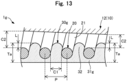
- a resin layer 30g includes a surface layer 31g.
- the shape of the surface layer 31g in the cross section illustrated in Fig. 13 is linear without any irregularities.
- the surface layer 31g may be formed of a material similar to that of the surface layer 31 according to the first example.
- the surface layer 31g whose cross section is linear may be formed as follows. That is, a resin material having flexibility is wound around the outer peripheral surface of the coil body 20. Next, the resin material is covered with a heat-shrinkable tube having a flat outer surface (no irregularities) and then heated.
- the molten resin material flows into the core shaft 10 from the gap C1 to form the protruding portion 32 and the surface layer 31g whose cross section is linear. Finally, the coil body 20 formed with the protruding portion 32 and the surface layer 31g is assembled to the core shaft 10.
- the surface layer 31g can function in various forms as long as the surface layer 31g covers at least the outer peripheral surface of the coil body 20.
- the guide wire 1g according to the fifth example can also exhibit a similar effect to the above-described first example.
- Fig. 14 is a partial enlarged view of a guide wire 1h according to a fourth embodiment.
- a resin layer 30h includes a protruding portion 32h1, a protruding portion 32h2, a protruding portion 32h3, and a protruding portion 32h4.
- the protruding portions 32h1 to 32h4 each have different shapes.
- the shape of the protruding portion 32h1 is a substantially triangular shape
- the shape of the protruding portion 32h2 is a trapezoidal shape
- the shape of the protruding portion 32h3 is a substantially triangular shape having a height different from that of the protruding portion 32h1
- the shape of the protruding portion 32h4 is a trapezoidal shape having a height different from that of the protruding portion 32h2.
- the protruding portion 32h1 and the protruding portion 32h2 contact the core shaft 10.
- the protruding portion 32h3 and the protruding portion 32h4 do not contact the core shaft 10.
- the protruding portions 32h1 to 32h4 may be formed by using a material and manufacturing method similar to those of the protruding portion 32 of the first example and the protruding portion 32f of the fourth example.
- the guide wire 1h may include various shapes of the protruding portions 32h1 to 32h4 as long as the protruding portions 32h1 to 32h4 extend toward the core shaft 10 through the gap C1 between the adjacent wires 21 of the coil body 20, and extend toward the core shaft 10 relative to the inner peripheral surface of the coil body 20. Further, the shapes of the protruding portions 32h1 to 32h4 may be different from each other as illustrated in Fig. 14 .
- the guide wire 1h according to the fourth embodiment can also exhibit a similar effect to the above-described first embodiment.
- the configuration of the guide wire 1 can be variously modified.
- the guide wire 1 may have a configuration that does not include the second tapered part 14 and the second large-diameter part 15 (that is, a configuration in which the core shaft 10 is entirely covered with the coil body 20).
- the guide wire 1 may be configured to not include a tapered part and have the same diameter over the entire region in the axis O direction.
- the configuration of the coil body 20 can be variously modified.
- the coil body 20 may be arranged to cover the second tapered part 14 and the second large-diameter part 15 of the core shaft 10 in addition to the small-diameter part 11 to the first large-diameter part 13 of the core shaft 10 described above.
- the arrangement of the closely wound part and the sparsely wound part of the coil body 20 may be optionally determined, and the closely wound part may be formed at a position other than the distal end part of the guide wire 1 (for example, at an almost center part in the axis O direction).
- configurations of the resin layer 30 have been described.
- the configuration of the resin layer 30 can be variously modified.
- at least one of the distal end resin layer 38 and the proximal end resin layer 39 included in the resin layer 30 may be omitted.
- a configuration in which the resin layer 30 is not provided in the closely wound part of the coil body 20 ( Fig. 9 , fourth embodiment) may be employed.
- the resin layer 30 may include the surface layer 31, the protruding portion 32 ( Fig. 2 ) not contacting with the core shaft 10, and the resin film 34 ( Fig. 11 ).
- the protruding portion 32 of the first example ( Fig. 2 , the configuration in which the protruding portion 32 does not contact the core shaft 10) may be adopted for a first region in the axis O direction
- the protruding portion 32a of the first embodiment of the invention ( Fig. 5 , the configuration in which the protruding portion 32a contacts the core shaft 10) may be adopted for a second region
- the protruding portion 32b of the second embodiment of the invention, ( Fig. 7 , the configuration in which the protruding portion 32b is joined to the core shaft 10) may be adopted for a third region.
- the positions of the first to third regions may be optionally determined in consideration of the performance (slidability, thrombus adhesion preventing property, operability, etc.) required for the guide wire 1. Further, some of the first to third regions may be omitted, and the first and second regions may constitute the guide wire 1, the first and third regions may constitute the guide wire 1, or the second and third regions may constitute the guide wire 1.
Landscapes
- Health & Medical Sciences (AREA)
- Life Sciences & Earth Sciences (AREA)
- Biophysics (AREA)
- Pulmonology (AREA)
- Engineering & Computer Science (AREA)
- Anesthesiology (AREA)
- Biomedical Technology (AREA)
- Heart & Thoracic Surgery (AREA)
- Hematology (AREA)
- Animal Behavior & Ethology (AREA)
- General Health & Medical Sciences (AREA)
- Public Health (AREA)
- Veterinary Medicine (AREA)
- Media Introduction/Drainage Providing Device (AREA)
Claims (4)
- Führungsdraht (1a-1e, 1h), aufweisend:einen Kernschaft (10);einen Spulenkörper (20, 20c), der durch Wickeln eines Drahtes um den Kernschaft (10) gebildet ist; undeine Harzschicht (30a, 30b, 30e, 30h), die mindestens eine äußere Umfangsfläche des Spulenkörpers (20, 20c) bedeckt, wobeider Spulenkörper (20, 20c) einen spärlich gewickelten Teil umfasst, in dem eine Lücke zwischen benachbarten Drähten ausgebildet ist,zwischen dem Spulenkörper (20, 20c) und dem Kernschaft (10) ein Hohlraum ausgebildet ist, unddie Harzschicht (30a, 30b, 30e, 30h) einen vorstehenden Abschnitt (32a, 32b, 32e, 32h1, 32h2) umfasst, der durch die Lücke zwischen den benachbarten Drähten in dem spärlich gewickelten Teil in Richtung des Kernschaft vorsteht, und der vorstehende Abschnitt (32a, 32b, 32e, 32h1, 32h2) sich in Richtung des Kernschafts (10) relativ zu einer inneren Umfangsfläche des Spulenkörpers (20, 20c) erstreckt, dadurch gekennzeichnet, dassder vorstehende Abschnitt (32a, 32b, 32e, 32h1, 32h2) den Kernschaft (10) berührt.
- Führungsdraht (1b) nach Anspruch 1, wobei
der vorstehende Abschnitt (32b) mit dem Kernschaft (10) verbunden ist. - Führungsdraht (1e) nach Anspruch 1, der ferner aufweist:einen Harzfilm (34), der eine äußere Umfangsfläche des Kernschafts (10) bedeckt, wobeider vorstehende Abschnitt (32e) mit dem Harzfilm (34) verbunden ist.
- Führungsdraht (1c) nach einem der Ansprüche 1 bis 3, der ferner aufweist:einen inneren Spulenkörper (40) an einer Innenseite des Spulenkörpers (20c), der durch Wickeln eines Drahtes um den Kernschaft (10) gebildet ist, wobeider innere Spulenkörper (40) eine Länge aufweist, die kürzer ist als eine Länge des Spulenkörpers (20c) in einer axialen Richtung, undder spärlich gewickelte Teil an einem Abschnitt ausgebildet ist, wo der Spulenkörper (20c) den inneren Spulenkörper (40) nicht bedeckt.
Applications Claiming Priority (1)
| Application Number | Priority Date | Filing Date | Title |
|---|---|---|---|
| PCT/JP2018/017468 WO2019211903A1 (ja) | 2018-05-01 | 2018-05-01 | ガイドワイヤ |
Publications (3)
| Publication Number | Publication Date |
|---|---|
| EP3789072A1 EP3789072A1 (de) | 2021-03-10 |
| EP3789072A4 EP3789072A4 (de) | 2021-12-22 |
| EP3789072B1 true EP3789072B1 (de) | 2024-10-30 |
Family
ID=68386395
Family Applications (1)
| Application Number | Title | Priority Date | Filing Date |
|---|---|---|---|
| EP18917477.4A Active EP3789072B1 (de) | 2018-05-01 | 2018-05-01 | Führungsdraht |
Country Status (5)
| Country | Link |
|---|---|
| US (1) | US20210046288A1 (de) |
| EP (1) | EP3789072B1 (de) |
| JP (1) | JP6986144B2 (de) |
| CN (2) | CN112135655B (de) |
| WO (1) | WO2019211903A1 (de) |
Families Citing this family (7)
| Publication number | Priority date | Publication date | Assignee | Title |
|---|---|---|---|---|
| JP7474589B2 (ja) * | 2019-12-12 | 2024-04-25 | 朝日インテック株式会社 | ガイドワイヤ、ガイドワイヤの製造方法 |
| JP7428552B2 (ja) * | 2020-03-11 | 2024-02-06 | 朝日インテック株式会社 | ガイドワイヤ |
| JP7538743B2 (ja) * | 2021-03-03 | 2024-08-22 | 朝日インテック株式会社 | ガイドワイヤ |
| JP7550710B2 (ja) * | 2021-04-30 | 2024-09-13 | 朝日インテック株式会社 | ガイドワイヤ |
| EP4454693A4 (de) * | 2021-12-21 | 2025-07-09 | Asahi Intecc Co Ltd | Medizinisches instrument |
| JPWO2024116319A1 (de) * | 2022-11-30 | 2024-06-06 | ||
| JPWO2024134751A1 (de) * | 2022-12-20 | 2024-06-27 |
Citations (1)
| Publication number | Priority date | Publication date | Assignee | Title |
|---|---|---|---|---|
| JPS51136979A (en) * | 1975-02-18 | 1976-11-26 | Fujita Shiyouten Kk | Unwoven fabric with good water absorptive and draining property |
Family Cites Families (26)
| Publication number | Priority date | Publication date | Assignee | Title |
|---|---|---|---|---|
| KR100721049B1 (ko) * | 2003-01-10 | 2007-05-23 | 가부시키가이샤 가네카 | 색전 형성용 체내 유치 코일 |
| US7182735B2 (en) * | 2003-02-26 | 2007-02-27 | Scimed Life Systems, Inc. | Elongated intracorporal medical device |
| US7553287B2 (en) * | 2003-10-30 | 2009-06-30 | Boston Scientific Scimed, Inc. | Guidewire having an embedded matrix polymer |
| JP3810413B2 (ja) * | 2004-03-29 | 2006-08-16 | 朝日インテック株式会社 | 医療用ガイドワイヤ |
| US20060047224A1 (en) * | 2004-09-01 | 2006-03-02 | Ryan Grandfield | Polymer coated guide wire |
| JP3940161B1 (ja) * | 2006-07-03 | 2007-07-04 | 朝日インテック株式会社 | 医療用ガイドワイヤ、医療用ガイドワイヤとマイクロカテーテルとの組立体、および医療用ガイドワイヤとバルーンカテーテルとガイディングカテーテルとの組立体 |
| JP4987531B2 (ja) | 2007-03-27 | 2012-07-25 | 日本ライフライン株式会社 | 医療用ガイドワイヤおよびその製造方法 |
| EP2143460B1 (de) * | 2007-05-09 | 2015-07-22 | Japan Science and Technology Agency | Führungsdraht und stent |
| US9180278B2 (en) * | 2008-08-11 | 2015-11-10 | Terumo Kabushiki Kaisha | Medical instrument |
| AU2010250563B2 (en) * | 2009-05-20 | 2015-07-02 | Japan Lifeline Co., Ltd. | Medical guide wire |
| JP5628515B2 (ja) * | 2009-12-18 | 2014-11-19 | 株式会社パイオラックスメディカルデバイス | ガイドワイヤ |
| AU2011230767B2 (en) * | 2010-03-26 | 2014-12-11 | Terumo Kabushiki Kaisha | Guide wire |
| JP5382881B2 (ja) * | 2011-06-15 | 2014-01-08 | 朝日インテック株式会社 | ガイドワイヤ |
| JP2013106854A (ja) * | 2011-11-22 | 2013-06-06 | Asahi Intecc Co Ltd | ガイドワイヤ |
| WO2013114985A1 (ja) * | 2012-02-01 | 2013-08-08 | 株式会社パイオラックスメディカルデバイス | ガイドワイヤ |
| EP2826516B1 (de) * | 2012-03-16 | 2019-04-17 | Terumo Kabushiki Kaisha | Führungsdraht |
| JP2013192914A (ja) * | 2012-03-23 | 2013-09-30 | Asahi Intecc Co Ltd | ガイドワイヤ |
| JP5565847B1 (ja) * | 2013-09-04 | 2014-08-06 | 株式会社エフエムディ | 医療用ガイドワイヤ |
| JP6148587B2 (ja) * | 2013-09-24 | 2017-06-14 | 朝日インテック株式会社 | ガイドワイヤ |
| JP5904672B2 (ja) * | 2013-09-25 | 2016-04-20 | 朝日インテック株式会社 | ガイドワイヤ |
| JP5971865B2 (ja) * | 2013-09-25 | 2016-08-17 | 朝日インテック株式会社 | ガイドワイヤ |
| JP5896479B2 (ja) * | 2013-09-25 | 2016-03-30 | 朝日インテック株式会社 | ガイドワイヤ |
| JP5709224B2 (ja) * | 2013-11-25 | 2015-04-30 | 朝日インテック株式会社 | 医療用ガイドワイヤ |
| JP6245760B2 (ja) * | 2014-09-16 | 2017-12-13 | 朝日インテック株式会社 | ガイドワイヤ |
| JP2017221562A (ja) * | 2016-06-17 | 2017-12-21 | 朝日インテック株式会社 | ガイドワイヤ |
| WO2018062155A1 (ja) * | 2016-09-30 | 2018-04-05 | テルモ株式会社 | ガイドワイヤ |
-
2018
- 2018-05-01 CN CN201880092933.4A patent/CN112135655B/zh active Active
- 2018-05-01 JP JP2020516995A patent/JP6986144B2/ja active Active
- 2018-05-01 EP EP18917477.4A patent/EP3789072B1/de active Active
- 2018-05-01 WO PCT/JP2018/017468 patent/WO2019211903A1/ja not_active Ceased
- 2018-05-01 CN CN202310837516.0A patent/CN116870335A/zh active Pending
-
2020
- 2020-10-30 US US17/085,479 patent/US20210046288A1/en active Pending
Patent Citations (1)
| Publication number | Priority date | Publication date | Assignee | Title |
|---|---|---|---|---|
| JPS51136979A (en) * | 1975-02-18 | 1976-11-26 | Fujita Shiyouten Kk | Unwoven fabric with good water absorptive and draining property |
Also Published As
| Publication number | Publication date |
|---|---|
| CN112135655A (zh) | 2020-12-25 |
| JPWO2019211903A1 (ja) | 2021-05-13 |
| EP3789072A4 (de) | 2021-12-22 |
| US20210046288A1 (en) | 2021-02-18 |
| CN112135655B (zh) | 2023-06-13 |
| WO2019211903A1 (ja) | 2019-11-07 |
| JP6986144B2 (ja) | 2021-12-22 |
| EP3789072A1 (de) | 2021-03-10 |
| CN116870335A (zh) | 2023-10-13 |
Similar Documents
| Publication | Publication Date | Title |
|---|---|---|
| EP3789072B1 (de) | Führungsdraht | |
| EP2799105B1 (de) | Führungsdraht | |
| EP2832397A1 (de) | Medizinisches instrument und verfahren zur herstellung des medizinischen instruments | |
| KR20230093530A (ko) | 카테터 및 카테터의 제조 방법 | |
| JP2015208425A (ja) | カテーテル | |
| KR102184238B1 (ko) | 장척 의료용 부재 | |
| US11400262B2 (en) | Guidewire having external coil with sections of different winding pitches and resin coatings | |
| JP7162957B2 (ja) | カテーテル | |
| JP6928203B2 (ja) | 分岐血管挿入用カテーテル | |
| EP3967356A1 (de) | Führungsdraht | |
| US11484687B2 (en) | Catheter | |
| JP7262557B2 (ja) | ガイドワイヤ | |
| US20250288779A1 (en) | Medical device and method of manufacturing medical device | |
| KR102131490B1 (ko) | 가이드 와이어 | |
| WO2018185917A1 (ja) | 管状体及びその管状体を備えたカテーテル | |
| JP7389123B2 (ja) | ガイドワイヤ | |
| EP2810682B1 (de) | Führungsdraht | |
| WO2021181936A1 (ja) | ガイドワイヤ | |
| JP6667024B2 (ja) | カテーテル | |
| CN116472083B (zh) | 导丝 | |
| JP6719809B2 (ja) | カテーテル及びバルーンカテーテル | |
| JP2023129469A (ja) | 回転伝達構造体、カテーテル、及びガイドワイヤ | |
| WO2025187065A1 (ja) | 医療デバイス | |
| JPH09308692A (ja) | カテーテル |
Legal Events
| Date | Code | Title | Description |
|---|---|---|---|
| STAA | Information on the status of an ep patent application or granted ep patent |
Free format text: STATUS: THE INTERNATIONAL PUBLICATION HAS BEEN MADE |
|
| PUAI | Public reference made under article 153(3) epc to a published international application that has entered the european phase |
Free format text: ORIGINAL CODE: 0009012 |
|
| STAA | Information on the status of an ep patent application or granted ep patent |
Free format text: STATUS: REQUEST FOR EXAMINATION WAS MADE |
|
| 17P | Request for examination filed |
Effective date: 20201027 |
|
| AK | Designated contracting states |
Kind code of ref document: A1 Designated state(s): AL AT BE BG CH CY CZ DE DK EE ES FI FR GB GR HR HU IE IS IT LI LT LU LV MC MK MT NL NO PL PT RO RS SE SI SK SM TR |
|
| AX | Request for extension of the european patent |
Extension state: BA ME |
|
| DAV | Request for validation of the european patent (deleted) | ||
| DAX | Request for extension of the european patent (deleted) | ||
| A4 | Supplementary search report drawn up and despatched |
Effective date: 20211123 |
|
| RIC1 | Information provided on ipc code assigned before grant |
Ipc: A61M 25/09 20060101AFI20211117BHEP |
|
| GRAP | Despatch of communication of intention to grant a patent |
Free format text: ORIGINAL CODE: EPIDOSNIGR1 |
|
| STAA | Information on the status of an ep patent application or granted ep patent |
Free format text: STATUS: GRANT OF PATENT IS INTENDED |
|
| INTG | Intention to grant announced |
Effective date: 20240528 |
|
| GRAS | Grant fee paid |
Free format text: ORIGINAL CODE: EPIDOSNIGR3 |
|
| GRAA | (expected) grant |
Free format text: ORIGINAL CODE: 0009210 |
|
| STAA | Information on the status of an ep patent application or granted ep patent |
Free format text: STATUS: THE PATENT HAS BEEN GRANTED |
|
| AK | Designated contracting states |
Kind code of ref document: B1 Designated state(s): AL AT BE BG CH CY CZ DE DK EE ES FI FR GB GR HR HU IE IS IT LI LT LU LV MC MK MT NL NO PL PT RO RS SE SI SK SM TR |
|
| REG | Reference to a national code |
Ref country code: GB Ref legal event code: FG4D |
|
| REG | Reference to a national code |
Ref country code: CH Ref legal event code: EP |
|
| REG | Reference to a national code |
Ref country code: DE Ref legal event code: R096 Ref document number: 602018076134 Country of ref document: DE |
|
| REG | Reference to a national code |
Ref country code: IE Ref legal event code: FG4D |
|
| REG | Reference to a national code |
Ref country code: LT Ref legal event code: MG9D |
|
| REG | Reference to a national code |
Ref country code: NL Ref legal event code: MP Effective date: 20241030 |
|
| PG25 | Lapsed in a contracting state [announced via postgrant information from national office to epo] |
Ref country code: HR Free format text: LAPSE BECAUSE OF FAILURE TO SUBMIT A TRANSLATION OF THE DESCRIPTION OR TO PAY THE FEE WITHIN THE PRESCRIBED TIME-LIMIT Effective date: 20241030 Ref country code: PT Free format text: LAPSE BECAUSE OF FAILURE TO SUBMIT A TRANSLATION OF THE DESCRIPTION OR TO PAY THE FEE WITHIN THE PRESCRIBED TIME-LIMIT Effective date: 20250228 Ref country code: IS Free format text: LAPSE BECAUSE OF FAILURE TO SUBMIT A TRANSLATION OF THE DESCRIPTION OR TO PAY THE FEE WITHIN THE PRESCRIBED TIME-LIMIT Effective date: 20250228 |
|
| PG25 | Lapsed in a contracting state [announced via postgrant information from national office to epo] |
Ref country code: FI Free format text: LAPSE BECAUSE OF FAILURE TO SUBMIT A TRANSLATION OF THE DESCRIPTION OR TO PAY THE FEE WITHIN THE PRESCRIBED TIME-LIMIT Effective date: 20241030 Ref country code: NL Free format text: LAPSE BECAUSE OF FAILURE TO SUBMIT A TRANSLATION OF THE DESCRIPTION OR TO PAY THE FEE WITHIN THE PRESCRIBED TIME-LIMIT Effective date: 20241030 |
|
| REG | Reference to a national code |
Ref country code: AT Ref legal event code: MK05 Ref document number: 1736327 Country of ref document: AT Kind code of ref document: T Effective date: 20241030 |
|
| PG25 | Lapsed in a contracting state [announced via postgrant information from national office to epo] |
Ref country code: BG Free format text: LAPSE BECAUSE OF FAILURE TO SUBMIT A TRANSLATION OF THE DESCRIPTION OR TO PAY THE FEE WITHIN THE PRESCRIBED TIME-LIMIT Effective date: 20241030 |
|
| PG25 | Lapsed in a contracting state [announced via postgrant information from national office to epo] |
Ref country code: ES Free format text: LAPSE BECAUSE OF FAILURE TO SUBMIT A TRANSLATION OF THE DESCRIPTION OR TO PAY THE FEE WITHIN THE PRESCRIBED TIME-LIMIT Effective date: 20241030 |
|
| PG25 | Lapsed in a contracting state [announced via postgrant information from national office to epo] |
Ref country code: NO Free format text: LAPSE BECAUSE OF FAILURE TO SUBMIT A TRANSLATION OF THE DESCRIPTION OR TO PAY THE FEE WITHIN THE PRESCRIBED TIME-LIMIT Effective date: 20250130 |
|
| PG25 | Lapsed in a contracting state [announced via postgrant information from national office to epo] |
Ref country code: GR Free format text: LAPSE BECAUSE OF FAILURE TO SUBMIT A TRANSLATION OF THE DESCRIPTION OR TO PAY THE FEE WITHIN THE PRESCRIBED TIME-LIMIT Effective date: 20250131 Ref country code: AT Free format text: LAPSE BECAUSE OF FAILURE TO SUBMIT A TRANSLATION OF THE DESCRIPTION OR TO PAY THE FEE WITHIN THE PRESCRIBED TIME-LIMIT Effective date: 20241030 Ref country code: LV Free format text: LAPSE BECAUSE OF FAILURE TO SUBMIT A TRANSLATION OF THE DESCRIPTION OR TO PAY THE FEE WITHIN THE PRESCRIBED TIME-LIMIT Effective date: 20241030 |
|
| PG25 | Lapsed in a contracting state [announced via postgrant information from national office to epo] |
Ref country code: PL Free format text: LAPSE BECAUSE OF FAILURE TO SUBMIT A TRANSLATION OF THE DESCRIPTION OR TO PAY THE FEE WITHIN THE PRESCRIBED TIME-LIMIT Effective date: 20241030 |
|
| PG25 | Lapsed in a contracting state [announced via postgrant information from national office to epo] |
Ref country code: RS Free format text: LAPSE BECAUSE OF FAILURE TO SUBMIT A TRANSLATION OF THE DESCRIPTION OR TO PAY THE FEE WITHIN THE PRESCRIBED TIME-LIMIT Effective date: 20250130 |
|
| PG25 | Lapsed in a contracting state [announced via postgrant information from national office to epo] |
Ref country code: SM Free format text: LAPSE BECAUSE OF FAILURE TO SUBMIT A TRANSLATION OF THE DESCRIPTION OR TO PAY THE FEE WITHIN THE PRESCRIBED TIME-LIMIT Effective date: 20241030 |
|
| PGFP | Annual fee paid to national office [announced via postgrant information from national office to epo] |
Ref country code: DE Payment date: 20250521 Year of fee payment: 8 |
|
| PG25 | Lapsed in a contracting state [announced via postgrant information from national office to epo] |
Ref country code: DK Free format text: LAPSE BECAUSE OF FAILURE TO SUBMIT A TRANSLATION OF THE DESCRIPTION OR TO PAY THE FEE WITHIN THE PRESCRIBED TIME-LIMIT Effective date: 20241030 |
|
| PGFP | Annual fee paid to national office [announced via postgrant information from national office to epo] |
Ref country code: GB Payment date: 20250527 Year of fee payment: 8 |
|
| PG25 | Lapsed in a contracting state [announced via postgrant information from national office to epo] |
Ref country code: EE Free format text: LAPSE BECAUSE OF FAILURE TO SUBMIT A TRANSLATION OF THE DESCRIPTION OR TO PAY THE FEE WITHIN THE PRESCRIBED TIME-LIMIT Effective date: 20241030 |
|
| PGFP | Annual fee paid to national office [announced via postgrant information from national office to epo] |
Ref country code: FR Payment date: 20250528 Year of fee payment: 8 |
|
| PG25 | Lapsed in a contracting state [announced via postgrant information from national office to epo] |
Ref country code: RO Free format text: LAPSE BECAUSE OF FAILURE TO SUBMIT A TRANSLATION OF THE DESCRIPTION OR TO PAY THE FEE WITHIN THE PRESCRIBED TIME-LIMIT Effective date: 20241030 |
|
| PG25 | Lapsed in a contracting state [announced via postgrant information from national office to epo] |
Ref country code: SK Free format text: LAPSE BECAUSE OF FAILURE TO SUBMIT A TRANSLATION OF THE DESCRIPTION OR TO PAY THE FEE WITHIN THE PRESCRIBED TIME-LIMIT Effective date: 20241030 |
|
| PG25 | Lapsed in a contracting state [announced via postgrant information from national office to epo] |
Ref country code: CZ Free format text: LAPSE BECAUSE OF FAILURE TO SUBMIT A TRANSLATION OF THE DESCRIPTION OR TO PAY THE FEE WITHIN THE PRESCRIBED TIME-LIMIT Effective date: 20241030 |
|
| PG25 | Lapsed in a contracting state [announced via postgrant information from national office to epo] |
Ref country code: IT Free format text: LAPSE BECAUSE OF FAILURE TO SUBMIT A TRANSLATION OF THE DESCRIPTION OR TO PAY THE FEE WITHIN THE PRESCRIBED TIME-LIMIT Effective date: 20241030 |
|
| REG | Reference to a national code |
Ref country code: DE Ref legal event code: R097 Ref document number: 602018076134 Country of ref document: DE |
|
| PLBE | No opposition filed within time limit |
Free format text: ORIGINAL CODE: 0009261 |
|
| STAA | Information on the status of an ep patent application or granted ep patent |
Free format text: STATUS: NO OPPOSITION FILED WITHIN TIME LIMIT |
|
| PG25 | Lapsed in a contracting state [announced via postgrant information from national office to epo] |
Ref country code: SE Free format text: LAPSE BECAUSE OF FAILURE TO SUBMIT A TRANSLATION OF THE DESCRIPTION OR TO PAY THE FEE WITHIN THE PRESCRIBED TIME-LIMIT Effective date: 20241030 |
|
| 26N | No opposition filed |
Effective date: 20250731 |
|
| REG | Reference to a national code |
Ref country code: CH Ref legal event code: U11 Free format text: ST27 STATUS EVENT CODE: U-0-0-U10-U11 (AS PROVIDED BY THE NATIONAL OFFICE) Effective date: 20251113 |