WO2018062155A1 - ガイドワイヤ - Google Patents
ガイドワイヤ Download PDFInfo
- Publication number
- WO2018062155A1 WO2018062155A1 PCT/JP2017/034695 JP2017034695W WO2018062155A1 WO 2018062155 A1 WO2018062155 A1 WO 2018062155A1 JP 2017034695 W JP2017034695 W JP 2017034695W WO 2018062155 A1 WO2018062155 A1 WO 2018062155A1
- Authority
- WO
- WIPO (PCT)
- Prior art keywords
- wire
- guide wire
- fixing member
- coil
- rigidity
- Prior art date
Links
Images


Classifications
-
- A—HUMAN NECESSITIES
- A61—MEDICAL OR VETERINARY SCIENCE; HYGIENE
- A61M—DEVICES FOR INTRODUCING MEDIA INTO, OR ONTO, THE BODY; DEVICES FOR TRANSDUCING BODY MEDIA OR FOR TAKING MEDIA FROM THE BODY; DEVICES FOR PRODUCING OR ENDING SLEEP OR STUPOR
- A61M25/00—Catheters; Hollow probes
-
- A—HUMAN NECESSITIES
- A61—MEDICAL OR VETERINARY SCIENCE; HYGIENE
- A61M—DEVICES FOR INTRODUCING MEDIA INTO, OR ONTO, THE BODY; DEVICES FOR TRANSDUCING BODY MEDIA OR FOR TAKING MEDIA FROM THE BODY; DEVICES FOR PRODUCING OR ENDING SLEEP OR STUPOR
- A61M25/00—Catheters; Hollow probes
- A61M25/01—Introducing, guiding, advancing, emplacing or holding catheters
- A61M25/09—Guide wires
Definitions
- the present invention relates to a guide wire.
- the guide wire introduces and guides catheters used for treatment of difficult surgical sites or treatment for the purpose of minimally invasive to the human body, angiographic examination and treatment in heart disease, etc. Is used.
- the tip of the guide wire is projected from the tip of the balloon catheter under fluoroscopy, and the target site is the target site together with the balloon catheter. Insert the coronary artery (coronary artery) just before the stenosis, then the tip of the guide wire passes through the stenosis, then guides the balloon catheter balloon to the stenosis along the guide wire and expands the balloon to stenosis. A treatment that spreads the part and secures blood flow is performed.
- a guide wire used in such a procedure a guide wire having a long shaft and a coil that passes through the tip of the long shaft is known (for example, see Patent Document 1). Further, the coil is provided with a plurality of coupling elements for fixing adjacent wires, and each coupling element is arranged in a scattered manner in the longitudinal direction and the circumferential direction of the coil.
- the guide wire may be used after being shaped in a state where the tip is bent prior to insertion into the living body. Thereby, it is excellent in operability in a blood vessel that is curved or bent relatively steeply.
- the guide wire is shaped so that the distal end is bent and deformed in order to find the entrance of the stenosis, and the proximal side of the distal end is selected to select the branch of the blood vessel.
- a curved portion having a larger curvature is formed to form a curved portion, and the two-stage shaped shape is used. Then, when the shape is collapsed using the guide wire, or when the initial shape does not match the lesion or the branch of the blood vessel, the shaping is performed again.
- the guidewire is thin and the operator's hand is wet, so if you grip the tip coil of the guidewire lightly, it will slip, and if you grip it hard, the coil will be deformed and damaged, making it difficult to reproduce the shape. There are some. If the first and second and subsequent shaping are not located on the same plane and the guide wire is bent three-dimensionally, it becomes very difficult to manipulate the guide wire in the blood vessel.
- An object of the present invention is to provide a guide wire that can reliably prevent operability from being lowered by shaping.
- a flexible wire body A coil provided so as to cover the tip of the wire main body and wound with a wire; A fixing member that is arranged between each of the wire rods adjacent to each other in the longitudinal direction of the wire main body and fixes the wire rods;
- the guide wire is characterized in that the fixing member is disposed along a longitudinal direction of the wire body and can be deformed by stress.
- the fixing member can be bent and extended,
- the load necessary for bending and deforming the coil so that the fixing member extends is larger than the load necessary for bending and deforming the coil so that the fixing member bends.
- Guide wire
- the fixing member has a long shape extending in the longitudinal direction of the wire main body, and fixes the wires adjacent to each other in the longitudinal direction of the wire main body together (1) or (2 ) Guide wire.
- each of the fixing members is arranged on a straight line along a longitudinal direction of the wire body.
- the resin material includes any of a silicon resin, an epoxy resin, and an acrylic resin.
- (10) It has a long and flexible wire body and a tubular member provided on the outer periphery of the distal end of the wire body, and is bent and deformed before being inserted into the living body.
- a guide wire that is used by shaping to form a part The tubular member is provided at a different position in the circumferential direction, and has a high-rigidity portion and a low-rigidity portion having different bending rigidity from each other,
- the shaping it is possible to perform a first operation of pressing radially inward from the high rigidity portion side and a second operation of pressing radially inward from the low rigidity portion side, Even if any of the first operation and the second operation is performed, the formed bending portion is in a bending state in which the high-rigidity portion is positioned on the inner side of the bending, and the same operation is performed.
- the tubular member includes a coil in which a wire is wound spirally, and a fixing member that fixes the wires adjacent to each other in the longitudinal direction of the wire body.
- a rigidity difference is generated between the fixed surface and the non-fixed surface of the coil by fixing one side of the coil circumference by the fixing member. That is, in the guide wire, a high-rigidity part and a low-rigidity part whose rigidity is lower than that of the high-rigidity part are formed.
- the coil rotates so that the high-rigidity portion is on the inside of the bend. Therefore, the surgeon can accurately shape the guide wire by bending the guide wire in a desired shape (direction).
- the bending rigidity and butting resistance of the coil is hardly increased (hardened), and the guide wire is shaped in two different positions in the longitudinal direction. Becomes easy.
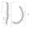
- FIG. 1A and 1B are longitudinal sectional views of a guide wire (first embodiment) according to the present invention, in which FIG. 1A is an enlarged view of a distal end portion and FIG. 1B is a sectional view taken along line AA.
- 2 is a longitudinal sectional view showing a process of shaping the distal end portion of the guide wire shown in FIG. 1, and FIG. 2 (a) is a view showing a state where a mandrel is pressed against the distal end portion from the outer side in the circumferential direction. (B) is a figure which shows the state which is moving the mandrel to the front end side from the state shown to (a).
- FIG. 3 is a longitudinal sectional view showing a process of shaping the distal end portion of the guide wire shown in FIG.
- FIG. 3 (c) is a view showing a state where the movement of the mandrel is completed
- FIG. It is a figure which shows the state which completed shaping.
- 4 is a longitudinal sectional view showing a process of shaping the distal end portion of the guide wire shown in FIG. 1
- FIG. 4 (a) is a view showing a state where a mandrel is pressed against the distal end portion from the outer side in the circumferential direction.
- (B) is a figure which shows the state which is moving the mandrel to the front end side from the state shown to (a).
- FIG. 5 is an enlarged side view of the wire rod of the coil that is deformed when pressed from the upper side in the drawing, where FIG.
- FIG. 5A is a view pressed from the state where the fixing member is positioned on the upper side
- (c) is the figure pressed from the state where the fixing member is located on the lower side
- (d) is the illustration where the fixing member is omitted.
- It is a figure which shows the state which pressed the coil.
- 6A and 6B are diagrams showing an example of shaping, in which FIG. 6A is a side view of the guide wire shown in FIG. 1, FIG. 6B is a diagram viewed from the direction of arrow B in FIG. These are figures which show the case where shaping is performed with the conventional guide wire.
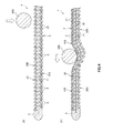
- FIG. 7A and 7B are partial cross-sectional views showing a guide wire (second embodiment) according to the present invention, in which FIG. 7A is an enlarged view of a tip portion, and FIG. 7B is a cross-sectional view taken along line BB.
- FIG. 8 is a partial cross-sectional view showing a guide wire (third embodiment) according to the present invention, in which (a) is an enlarged view of the distal end portion and (b) is a cross-sectional view taken along the line CC.
- FIG. 9 is a partial cross-sectional view showing a guide wire (fourth embodiment) according to the present invention, in which (a) is an enlarged view of the distal end portion and (b) is a cross-sectional view along the line DD.
- FIG. 1A and 1B are longitudinal sectional views of a guide wire (first embodiment) according to the present invention, in which FIG. 1A is an enlarged view of a distal end portion and FIG. 1B is a sectional view taken along line AA.
- 2 is a longitudinal sectional view showing a process of shaping the distal end portion of the guide wire shown in FIG. 1, and FIG. 2 (a) is a view showing a state where a mandrel is pressed against the distal end portion from the outer side in the circumferential direction.
- (B) is a figure which shows the state which is moving the mandrel to the front end side from the state shown to (a).
- FIG. 1A is an enlarged view of a distal end portion
- FIG. 1B is a sectional view taken along line AA.
- 2 is a longitudinal sectional view showing a process of shaping the distal end portion of the guide wire shown in FIG. 1
- FIG. 2 (a) is a view showing a state where a man
- FIG. 3 is a longitudinal sectional view showing a process of shaping the distal end portion of the guide wire shown in FIG. 1, wherein FIG. 3 (c) is a view showing a state where the movement of the mandrel is completed, and FIG. It is a figure which shows the state which completed shaping.
- 4 is a longitudinal sectional view showing a process of shaping the distal end portion of the guide wire shown in FIG. 1, and FIG. 4 (a) is a view showing a state where a mandrel is pressed against the distal end portion from the outer side in the circumferential direction.
- (B) is a figure which shows the state which is moving the mandrel to the front end side from the state shown to (a).
- FIG. 3 is a longitudinal sectional view showing a process of shaping the distal end portion of the guide wire shown in FIG. 1
- FIG. 4 (a) is a view showing a state where a mandrel is pressed against the distal end portion from the outer side in the circumferential direction
- FIG. 5 is an enlarged side view of the wire rod of the coil that is deformed when pressed from the upper side in the drawing, where FIG. 5A is a view pressed from the state where the fixing member is positioned on the upper side, and FIG. The figure pressed from the state where the fixing member is located on the back side of the paper, (c) is the figure pressed from the state where the fixing member is located on the lower side, and (d) is the illustration where the fixing member is omitted. It is a figure which shows the state which pressed the coil.
- 6A and 6B are diagrams showing an example of shaping, in which FIG. 6A is a side view of the guide wire shown in FIG. 1, FIG. 6B is a diagram viewed from the direction of arrow B in FIG. These are figures which show the case where shaping is performed with the conventional guide wire.
- the right side in FIGS. 1 to 4 (the same applies to FIGS. 7 to 9) is referred to as “base end”, and the left side is referred to as “tip”.
- the longitudinal direction of the guide wire is shortened, and the radial direction (thickness direction) of the guide wire is exaggerated, and the ratio of the longitudinal direction to the radial direction is schematically illustrated. Is different from the actual.
- a guide wire 1 shown in FIGS. 1A and 1B is a guide wire for a catheter that is used by being inserted into a lumen of a catheter including an endoscope.
- the guide wire 1 includes a wire body 10 and a spiral coil 2 (tubular member) that covers the outer peripheral portion on the distal end side of the wire body 10.
- the total length of the guide wire 1 is not particularly limited, for example, when the guide wire 1 is used for PCI, it is preferably 200 mm or more and 5000 mm or less, and more preferably 1000 mm or more and 3000 mm or less.
- the wire body 10 is composed of a long body having flexibility.
- the distal end portion 11 of the wire body 10 has a circular cross-sectional shape and a constant outer diameter over the entire length in the longitudinal direction.
- the proximal end portion of the distal end portion 11 is, for example, a tapered portion whose outer diameter gradually decreases toward the distal end side, or a constant outer diameter portion having a constant outer diameter and a larger outer diameter than the distal end portion 11. Etc. may be provided.
- the tip portion 11 is a portion that can be bent and deformed into a desired shape and used for shaping. This shaping is called “reshaping”.
- the distal end portion 11 is a portion mainly responsible for shaping. And by this shaping, the advancing direction of the guide wire 1 in the living body can be selected easily and reliably, and thus the operability of the guide wire 1 is remarkably improved.
- the constituent material of such a wire main body 10 is not specifically limited, For example, various metal materials, such as an alloy which shows pseudoelasticity including superelastic alloys, such as stainless steel, a piano wire, a cobalt-type alloy, a nickel titanium alloy, are used. be able to. Further, the wire body 10 may have a form in which wires made of different materials are joined, or may have a form in which wires made of the same or the same kind of material are joined.
- the coil 2 is provided so as to cover the outer periphery of the tip portion 11.
- the coil 2 has a distal end portion and a proximal end portion (not shown) fixed to the wire body 10 via a fixing member 5.
- a fixing member 5 By installing such a coil 2, for example, the contact area of the surface of the wire body 10 in the living body can be reduced, and sliding resistance can be reduced. As a result, the operability of the guide wire 1 is further improved.
- the coil 2 is formed by winding a wire 21 as a wire around the wire body 10, and the wires 21 adjacent in the longitudinal direction of the wire body 10 are separated from each other in a natural state. It is in a so-called sparse winding state.
- the coil 2 may be a so-called densely wound coil in which the strands 21 adjacent to each other in the longitudinal direction of the wire body 10 are in natural contact with each other.
- the tip 11 is separated from the coil 2 regardless of whether or not the shaping is performed. Thereby, the freedom degree of the shaping in the front-end
- tip part 11 is fully securable.
- the base end portion of the coil 2 may be fixed to the tapered portion or the constant outer diameter portion as described above, or may be fixed in the middle of the distal end portion 11 in the longitudinal direction.
- hydrophilic material examples include cellulose-based polymer materials, polyethylene oxide-based polymer materials, and maleic anhydride-based polymer materials (for example, maleic anhydride copolymers such as methyl vinyl ether-maleic anhydride copolymer).
- Acrylamide polymer substances for example, polyacrylamide, block copolymer of polyglycidyl methacrylate-dimethylacrylamide (PGMA-DMAA)), water-soluble nylon, polyvinyl alcohol, polyvinylpyrrolidone and the like.
- At least one fixing member 3 is provided between the strands 21 adjacent to each other in the longitudinal direction of the wire main body 10.
- the fixing member 3 only needs to be provided between the strands 21 of the coil 2, and may extend from between the strands 21 to the outer peripheral surface side or the inner peripheral surface side of the coil 2. . Further, the fixing member 3 may exist only between the strands 21 and may not protrude to the outer peripheral surface or inner peripheral surface of the coil 2.
- the fixing member 3 fixes a part of the adjacent strands 21. Thereby, the bending rigidity of the fixing
- the fixing member 3 when the distal end side of the coil 2 with respect to the central portion in the longitudinal direction is the distal end region 20, the fixing member 3 is disposed only in the distal end region 20, and is based on the distal end region 20. On the end side, the fixing member 3 is omitted.
- the fixing member 3 is provided in alignment along the longitudinal direction of the wire body 10. “Arranged” means that the fixing member 3 is arranged along the axial direction of the coil 2 within a certain range of the circumference of the coil 2.
- the guide wire 1 can exhibit the effects of the present invention as long as the guide wire 1 is disposed within an outer edge of the cross-sectional shape thereof, that is, within the range of about 90 ° of the circumference 360 ° of the coil 2.
- it if it is located in the range of about 10 degrees among 360 degrees of circumferences, it shall be arrange
- the fixing member 3 is provided at all between the strands 21 in the distal end region 20.
- the high-rigidity part 100 exists in any part of the longitudinal direction of the coil 2. Therefore, as will be described later, the guide wire 1 is excellent in operability.
- the fixing member 3 may be partially omitted from the distal end region 20. That is, the fixing member 3 does not have to be provided between all the strands 21 in the distal end region 20.
- the portion where the fixing member 3 is arranged and the portion where the fixing member 3 is omitted are alternately arranged, the portion where the fixing member 3 is arranged, and the fixing member 3
- the arrangement form is included in “equal intervals”, for example, when the omitted parts are arranged with regularity.
- the portion where the fixing member 3 is arranged and the portion where the fixing member 3 is omitted may be irregularly arranged.
- each fixing member 3 has the same width w when viewed from the outside in the radial direction of the coil 2. Thereby, the contact area of the strand 21 with the fixing member 3 is the same in any part of the coil 2, and the bending rigidity of the high-rigidity portion 100 can be made uniform along the longitudinal direction of the wire body 10.
- the width w of the fixing member 3 is preferably 10% or more and 90% or less of the maximum outer diameter ⁇ D of the coil 2, and is 50% or more and 70% or less. More preferred. As a result, the bending rigidity of the high-rigidity portion 100 can be sufficiently increased, and a difference in bending rigidity between the high-rigidity portion 100 and the low-rigidity portion 200 can be sufficiently ensured.
- Such a fixing member 3 is not particularly limited, and for example, a thermosetting adhesive, a photocurable adhesive, or the like can be used. Thereby, it is possible to easily adjust the degree of progress of curing.
- the adhesive is not particularly limited, and for example, a resin material such as a silicon resin, an epoxy resin, and an acrylic resin can be suitably used.
- a resin material such as a silicon resin, an epoxy resin, and an acrylic resin can be suitably used.
- the viscosity of the adhesive before curing is preferably 200 Pa ⁇ s or more and 8000 Pa ⁇ s or less, and more preferably 400 Pa ⁇ s or more and 800 Pa ⁇ s or less.
- the coil 2 is curved and deformed together with the tip 11 of the wire body 10 and used.
- the operability within a complicatedly curved or bent blood vessel is improved.
- the present invention has an effective configuration for preventing such a decrease in operability. This will be described below.
- molding the case where it performs using the mandrel 300 which is a hard round bar-shaped member is demonstrated.
- the first operation will be described with reference to FIGS. 2 and 3.
- First operation As shown in FIG. 2A, first, the mandrel 300 is pressed against the coil 2 from the high-rigidity portion 100 side located in the tip region 20. At this time, the mandrel 300 is pressed in a direction in which the mandrel 300 and the guide wire 1 are orthogonal to each other. As a result, the portion of the coil 2 and the tip portion 11 where the mandrel 300 is pressed and the vicinity thereof are curved and deformed so as to follow the mandrel 300. That is, the coil 2 and the distal end portion 11 are curved and deformed with the high-rigidity portion 100 as a curved inner side. At this time, as shown in FIG. 5A, the fixing member 3 is bent and deformed.
- the mandrel 300 is moved to the tip side while maintaining the state where the mandrel 300 is pressed against the guide wire 1. That is, the pressing position is moved to the distal end side along the longitudinal direction of the wire body 10 while pressing the guide wire 1 from the outside in the radial direction.
- the guide wire 1 forms the curved portion 400 that is curved and deformed with the high-rigidity portion 100 as the curved inner side.
- the second operation is an operation of pressing the mandrel 300 against the guide wire 1 from the low-rigidity portion 200 side that is a portion other than the high-rigidity portion 100 located in the distal end region 20.
- the mandrel 300 is pressed from the opposite side of the highly rigid part 100 through the wire main body 10 as an example is demonstrated.
- the mandrel 300 is pressed from the low rigidity portion 200 side. At this time, as in the first operation, the mandrel 300 is pressed in a direction in which the mandrel 300 and the guide wire 1 are orthogonal to each other.
- the guide wire 1 is provided with a fixing member 3, and when the shape is formed from a position different from the fixing member 3, as shown in FIGS. 5 (b) to 5 (c), the fixing member 3. Is stretched.
- the load is greater when the fixing member 3 extends than when the fixing member 3 bends. This is because the load necessary for the fixing member 3 to expand is larger than the load necessary for the fixing member 3 to bend.
- the load required when the coil 2 is bent and deformed so that the fixing member 3 is extended is larger than the load required when the coil 2 is bent and deformed so that the fixing member 3 is bent.
- the fixing member 3 is arranged inside the curve, and the coil 2 can be shaped similarly to the first operation, and the shaping is performed so that the shaped part is located on the same virtual plane F. Made.
- the rotational force of the coil 2 as described above is transmitted to the entire coil 2, and the coil 2 rotates.
- the fixing member 3 is positioned on the upper side in the figure.
- the mandrel 300 is moved to the front end side, maintaining the state which pressed the mandrel 300 against the guide wire 1.
- a curved portion 400 is formed that is curved and deformed with the high-rigidity portion 100 as the curved inner side (FIG. 3D). reference).
- the curved portion 400 formed in the distal end region 20 has the high-rigidity portion 100 regardless of whether the first operation or the second operation is performed. It will be in the curved state located inside a curve. That is, the bending portion 400 formed by the first operation and the bending portion 400 formed by the second operation are located on the same virtual plane F.
- the bending portion 400 having the same bending direction is formed even if the mandrel 300 is pressed and shaped from any radial position. Therefore, the user of the guide wire 1 can form the bending portion 400 having the same bending direction regardless of which direction the user presses.
- FIG. 6 (a) description will be given of shaping to form two bending portions 400.
- FIG. 400 after forming the bending portion 400 (hereinafter referred to as “curving portion 400A”) as described above, the bending portion 400B is formed on the proximal end side of the bending portion 400A.
- the curved portion 400B is formed by performing the first operation or the second operation.
- the guide wire 1 is configured to bend in the same direction regardless of whether the first operation or the second operation is performed.
- the bending portion 400A and the bending portion 400B located in the distal end region 20 are the same regardless of whether the first operation or the second operation is performed. It will be located on the plane F. That is, the user of the guide wire 1 can form the bending portion 400A and the bending portion 400B having the same bending direction regardless of which direction the user presses. Therefore, it is possible to accurately and reliably form the bending portion 400A and the bending portion 400B, which has been difficult in the past.
- the guide wire 1 it is possible to reliably prevent the operability from being lowered by shaping, and no matter what shape is used to shape the guide wire 1, It becomes a user's desired shape of the guide wire 1.
- the wire 21 of the coil 2 can be smoothly rotated as shown in FIG. . Therefore, the high-rigidity portion 100 is surely positioned inside the curve.
- the surgeon generally performs shaping while wearing a sterilized glove, so it was difficult to accurately shape the glove, but according to the guide wire 1, the sterilized glove was worn. Even in the state, the shaping can be performed accurately.
- Second Embodiment 7A and 7B are partial cross-sectional views showing a guide wire (second embodiment) according to the present invention, in which FIG. 7A is an enlarged view of a tip portion, and FIG. 7B is a cross-sectional view taken along line BB.
- the fixing member 3 ⁇ / b> A has a strip shape extending in the longitudinal direction of the wire body 10. This fixing member 3A fixes adjacent strands 21 collectively. Thereby, the effect similar to 1st Embodiment can be acquired.
- the fixing member 3A can be applied by a simple method in which the liquid fixing member 3A is linearly applied to the outer peripheral portion of the coil 2 using, for example, a brush.
- the fixing member 3 ⁇ / b> A has a portion that enters between the adjacent strands 21. Thereby, the contact area of 3 A of fixing members and the coil 2 increases, and the adhesive strength of 3 A of fixing members and the coil 2 can be raised.
- the fixing member 3 ⁇ / b> A may be provided only between the strands 21. Thereby, it can suppress that the coil 2 becomes hard too much, fixing the strands 21 by making thickness of 3 A of fixing members small.
- the lubricity coat can be uniformly applied to the outer peripheral surface of the coil 2.
- FIG. 8 is a partial cross-sectional view showing a guide wire (third embodiment) according to the present invention, in which (a) is an enlarged view of the distal end portion and (b) is a cross-sectional view taken along the line CC.
- This embodiment is the same as the first embodiment except that the shape of the tip of the wire body is different.
- the distal end portion 11 of the wire body 10 has a plate shape.
- tip part 11 of the wire main body 10 can be preferentially curved and deformed in the front direction and the back direction in FIG.
- each fixing member 3 is located on the extension of the distal end portion 11 in the thickness direction.
- FIG. 9 is a partial cross-sectional view showing a guide wire (fourth embodiment) according to the present invention, in which (a) is an enlarged view of the distal end portion and (b) is a cross-sectional view along the line DD.
- a pair of band-shaped fixing members 3 ⁇ / b> C are provided via the wire body 10.
- Each fixing member 3 ⁇ / b> C is provided along the longitudinal direction of the wire body 10.
- a pair of high-rigidity portions 100 are provided via the wire body 10 at the distal end portion of the guide wire 1C.
- the guide wire 1C as a whole is rotated by the pressing operation, and the space between the fixing members 3C is bent at a position where the fixing members 3C are not disposed outside the bending. That is, it is preferentially curved and deformed in the front direction and the back direction in FIG. 9A. Therefore, when the wire 21 of the coil 2 rotates in shaping, a pair of high-rigidity portions 100 are provided. The amount of rotation can be reduced. Therefore, it is possible to shape the shape more accurately.
- each part which comprises a guide wire is a thing of arbitrary structures which can exhibit the same function. Can be substituted. Moreover, arbitrary components may be added.
- the guide wire of the present invention may be a combination of any two or more configurations (features) of the above embodiments.
- the guide wire of the present invention includes a flexible wire main body, a coil provided so as to cover a distal end portion of the wire main body, and a wire formed by winding a wire, and the wire rods adjacent to each other in the longitudinal direction of the wire main body. And a fixing member that fixes the wires to each other.
- the fixing member is arranged along the longitudinal direction of the wire body and is deformable by stress. Therefore, it can prevent reliably that operativity falls by shaping. Therefore, the guide wire of the present invention has industrial applicability.
Abstract
ガイドワイヤ1は、可撓性を有するワイヤ本体11と、ワイヤ本体11の先端外周部に設けられたコイル2とを有し、生体内に挿入するのに先立って湾曲変形させて湾曲部を形成する形状付けが行われて用いられるものである。また、コイル2は、その周方向の異なる位置に設けられ、互いに曲げ剛性が異なる高剛性部100および低剛性部200を有するものである。そして、ガイドワイヤ1は、形状付けを行うに際し、高剛性部100側から径方向内側に押圧する第1の操作と、低剛性部200側から径方向内側に押圧する第2の操作とのうちのいずれの操作を行った場合であっても、形成される湾曲部は、高剛性部100が湾曲内側に位置する湾曲状態となり、かつ、同一の仮想平面上に位置している。
Description
本発明は、ガイドワイヤに関する。
ガイドワイヤは、外科的手術が困難な部位の治療、または人体への低侵襲を目的とした治療や、心臓疾患における血管造影の検査、治療などに用いられるカテーテルを目的部位へ導入、誘導するのに使用されている。
例えばPCI(Percutaneous Coronary Intervention:経皮的冠状動脈インターベンション)を行なう際には、X線透視下で、ガイドワイヤの先端をバルーンカテーテルの先端より突出させた状態で、バルーンカテーテルと共に目的部位である冠状動脈(冠動脈)の狭窄部の手前まで挿入し、次いでガイドワイヤの先端が狭窄部を通過し、その後バルーンカテーテルのバルーンをガイドワイヤに沿わせつつ狭窄部へ誘導し、バルーンを拡張して狭窄部を押し広げ、血流を確保するという治療を行う。
このような手技で用いられるガイドワイヤとしては、長尺状シャフトと、長尺状シャフトの先端部を挿通するコイルとを有するガイドワイヤが知られている(例えば、特許文献1参照)。また、このコイルには、隣り合う線材を固定する複数の結合要素が設けられており、各結合要素は、コイルの長手方向および周方向に散在して配置されている。
ところで、ガイドワイヤは、生体内に挿入するのに先立って先端部を湾曲した状態に形状付けを行って用いられる場合がある。これにより、比較的急峻に湾曲または屈曲した血管内での操作性に優れる。
さらに、ガイドワイヤには、狭窄部の入口を探るために先端部を湾曲変形させて湾曲部を形成する形状付けを行い、さらに、血管の分岐を選択するために、先端部よりも手元部側にさらに曲率が大きい湾曲部を形成する形状付けを行い、2段階の形状付けがなされた状態で用いられることがある。そして、ガイドワイヤを使用して形状が崩れた際や最初に付けた形状が病変や血管の分岐に合わなかった場合に再度、形状付けが行われる。
このように複数回の形状付けを行う場合、最初に形成した湾曲部の形状と、2回目以降に形成した湾曲部が同一平面となるように形状付けを行うことが熟練した術者であっても困難となる。
その理由としては、ガイドワイヤが細く、しかも、術者の手が濡れているため、ガイドワイヤの先端コイルを軽く掴むとすべり、強く掴むとコイルが変形破損するため形状を再現することが困難であることが挙げられる。最初と2回目以降の形状付けが、同一平面上に位置せず、ガイドワイヤが3次元に屈曲してしまうと、血管内でのガイドワイヤの操作が非常に困難となる。
このように、正確に形状付けを行うのは難しく、正確に形状付けを行わないと、ガイドワイヤの操作性が低下する。
本発明の目的は、形状付けを行うことによって操作性が低下するのを確実に防止することができるガイドワイヤを提供することにある。
このような目的は、下記(1)~(11)の本発明により達成される。
(1) 可撓性を有するワイヤ本体と、
前記ワイヤ本体の先端部を覆って設けられ、線材が巻回されてなるコイルと、
前記ワイヤ本体の長手方向に隣り合う前記各線材の間にそれぞれ配置され、前記線材同士を固定する固定部材とを備え、
前記固定部材は、前記ワイヤ本体の長手方向に沿って配置され、かつ、応力によって変形可能であることを特徴とするガイドワイヤ。
(1) 可撓性を有するワイヤ本体と、
前記ワイヤ本体の先端部を覆って設けられ、線材が巻回されてなるコイルと、
前記ワイヤ本体の長手方向に隣り合う前記各線材の間にそれぞれ配置され、前記線材同士を固定する固定部材とを備え、
前記固定部材は、前記ワイヤ本体の長手方向に沿って配置され、かつ、応力によって変形可能であることを特徴とするガイドワイヤ。
(2) 前記固定部材は、屈曲および伸長可能であり、
前記固定部材が伸長するように前記コイルを湾曲変形させる際に必要な荷重は、前記固定部材が屈曲するように前記コイルを湾曲変形させる際に必要な荷重よりも大きい上記(1)に記載のガイドワイヤ。
前記固定部材が伸長するように前記コイルを湾曲変形させる際に必要な荷重は、前記固定部材が屈曲するように前記コイルを湾曲変形させる際に必要な荷重よりも大きい上記(1)に記載のガイドワイヤ。
(3) 前記固定部材は、前記ワイヤ本体の長手方向に延在する長尺状をなし、前記ワイヤ本体の長手方向に隣り合う前記各線材同士を一括して固定する上記(1)または(2)に記載のガイドワイヤ。
(4) 前記固定部材は、前記ワイヤ本体の長手方向に隣り合う前記各線材の間にそれぞれ配置されている上記(1)または(2)に記載のガイドワイヤ。
(5) 前記各固定部材は、前記ワイヤ本体の長手方向に整列して配置されている上記(4)に記載のガイドワイヤ。
(6) 前記各固定部材は、前記ワイヤ本体の長手方向に沿った直線上に配置されている上記(5)に記載のガイドワイヤ。
(7) 前記固定部材は、樹脂材料を含んでいる上記(1)ないし(6)のいずれかに記載のガイドワイヤ。
(8) 前記樹脂材料は、シリコン系樹脂、エポキシ系樹脂およびアクリル系樹脂のうちのいずれかを含む上記(7)に記載のガイドワイヤ。
(9) 少なくとも前記コイルを覆い、湿潤することにより潤滑性を発現する被覆層を有する上記(1)ないし(8)のいずれかに記載のガイドワイヤ。
(10) 長尺状をなし、可撓性を有するワイヤ本体と、前記ワイヤ本体の先端外周部に設けられた管状部材とを有し、生体内に挿入するのに先立って湾曲変形させて湾曲部を形成する形状付けが行われて用いられるガイドワイヤであって、
前記管状部材は、周方向の異なる位置に設けられ、互いに曲げ剛性が異なる高剛性部および低剛性部を有するものであり、
前記形状付けを行うに際し、前記高剛性部側から径方向内側に押圧する第1の操作と、前記低剛性部側から径方向内側に押圧する第2の操作とを行うことが可能であり、
前記第1の操作および前記第2の操作のいずれの操作を行った場合であっても、形成される前記湾曲部は、前記高剛性部が湾曲内側に位置する湾曲状態となり、かつ、同一の仮想平面上に位置していることを特徴とするガイドワイヤ。
前記管状部材は、周方向の異なる位置に設けられ、互いに曲げ剛性が異なる高剛性部および低剛性部を有するものであり、
前記形状付けを行うに際し、前記高剛性部側から径方向内側に押圧する第1の操作と、前記低剛性部側から径方向内側に押圧する第2の操作とを行うことが可能であり、
前記第1の操作および前記第2の操作のいずれの操作を行った場合であっても、形成される前記湾曲部は、前記高剛性部が湾曲内側に位置する湾曲状態となり、かつ、同一の仮想平面上に位置していることを特徴とするガイドワイヤ。
(11) 前記管状部材は、線材が螺旋状に巻回されたコイルと、前記ワイヤ本体の長手方向に隣り合う前記各線材同士を固定する固定部材とを有し、
前記管状部材のうち前記固定部材によって固定された固定部が前記高剛性部として機能し、前記管状部材のうち前記固定部を除く部分が前記低剛性部として機能する上記(10)に記載のガイドワイヤ。
前記管状部材のうち前記固定部材によって固定された固定部が前記高剛性部として機能し、前記管状部材のうち前記固定部を除く部分が前記低剛性部として機能する上記(10)に記載のガイドワイヤ。
本発明のガイドワイヤでは、固定部材により、コイルの円周上の一方の片側を固定することで、コイルの固定面と非固定面に剛性の差が生じる。すなわち、ガイドワイヤでは、高剛性部と、高剛性部よりも剛性が低い低剛性部が形成されることとなる。また、高剛性部側から径方向内側に押圧する第1の操作と、低剛性部側から径方向内側に押圧する第2の操作のうちのいずれの操作を行った場合であっても、高剛性部と低剛性部との剛性の差により、高剛性部が屈曲の内側となるようにコイルが回転する。よって、術者は、所望の形状(方向)にガイドワイヤを湾曲変形させて、形状付けを正確に行うことができる。
さらに、変形可能な固定部材を用いることでコイルの曲げ剛性や突き当て抵抗を大きく(硬く)することがほとんどなく、かつ、ガイドワイヤにおいて長手方向に異なる2ヶ所に形状付けを行う2段階形状付けが容易となる。また、一度ガイドワイヤを使用して形状が崩れた際や最初に付けた形状が病変や血管の分岐に合わなかったなどにより、再度の形状付けが必要な場合がある。そのような複数回の形状付けを行っても、ガイドワイヤが3次元に屈曲せずに、同一仮想平面内に形状付けがなされるため、血管内でのガイドワイヤの操作が非常にすぐれたものになる。
以下、本発明のガイドワイヤを添付図面に示す好適な実施形態に基づいて詳細に説明する。
<第1実施形態>
図1は、本発明のガイドワイヤ(第1実施形態)の縦断面図であって、(a)が、先端部の拡大図、(b)が、A-A線断面図である。図2は、図1に示すガイドワイヤの先端部に対して形状付けを行う過程を示す縦断面図であって、(a)が、先端部にマンドレルを周方向外側から押しつけた状態を示す図、(b)が、(a)に示す状態からマンドレルを先端側に移動させている状態を示す図である。図3は、図1に示すガイドワイヤの先端部に対して形状付けを行う過程を示す縦断面図であって、(c)が、マンドレルの移動が完了した状態を示す図、(d)が、形状付けが完了した状態を示す図である。図4は、図1に示すガイドワイヤの先端部に対して形状付けを行う過程を示す縦断面図であって、(a)が、先端部にマンドレルを周方向外側から押しつけた状態を示す図、(b)が、(a)に示す状態からマンドレルを先端側に移動させている状態を示す図である。図5は、図中上側から押圧した際に変形するコイルの線材を拡大した側面図であって、(a)が、上側に固定部材が位置している状態から押圧した図、(b)が、固定部材が紙面奥側に位置している状態から押圧した図、(c)が、下側に固定部材が位置している状態から押圧した図、(d)が、固定部材が省略されたコイルを押圧した状態を示す図である。図6は、形状付けの一例を示す図であって、(a)が、図1に示すガイドワイヤの側面図、(b)が、(a)中矢印B方向から見た図、(c)が、従来のガイドワイヤで形状付けを行った場合を示す図である。
図1は、本発明のガイドワイヤ(第1実施形態)の縦断面図であって、(a)が、先端部の拡大図、(b)が、A-A線断面図である。図2は、図1に示すガイドワイヤの先端部に対して形状付けを行う過程を示す縦断面図であって、(a)が、先端部にマンドレルを周方向外側から押しつけた状態を示す図、(b)が、(a)に示す状態からマンドレルを先端側に移動させている状態を示す図である。図3は、図1に示すガイドワイヤの先端部に対して形状付けを行う過程を示す縦断面図であって、(c)が、マンドレルの移動が完了した状態を示す図、(d)が、形状付けが完了した状態を示す図である。図4は、図1に示すガイドワイヤの先端部に対して形状付けを行う過程を示す縦断面図であって、(a)が、先端部にマンドレルを周方向外側から押しつけた状態を示す図、(b)が、(a)に示す状態からマンドレルを先端側に移動させている状態を示す図である。図5は、図中上側から押圧した際に変形するコイルの線材を拡大した側面図であって、(a)が、上側に固定部材が位置している状態から押圧した図、(b)が、固定部材が紙面奥側に位置している状態から押圧した図、(c)が、下側に固定部材が位置している状態から押圧した図、(d)が、固定部材が省略されたコイルを押圧した状態を示す図である。図6は、形状付けの一例を示す図であって、(a)が、図1に示すガイドワイヤの側面図、(b)が、(a)中矢印B方向から見た図、(c)が、従来のガイドワイヤで形状付けを行った場合を示す図である。
なお、以下では、説明の都合上、図1~図4中(図7~図9についても同様)の右側を「基端」、左側を「先端」と言う。また、図では、理解を容易にするため、ガイドワイヤの長手方向を短縮し、ガイドワイヤの径方向(太さ方向)を誇張して模式的に図示しており、長手方向と径方向の比率は、実際とは異なる。
図1(a)および(b)に示すガイドワイヤ1は、内視鏡も含むカテーテルの内腔に挿入して用いられるカテーテル用ガイドワイヤである。このガイドワイヤ1は、ワイヤ本体10と、ワイヤ本体10の先端側外周部を覆う螺旋状のコイル2(管状部材)とを備えている。
ガイドワイヤ1の全長は、特に限定されないが、例えばガイドワイヤ1をPCIに用いる場合には、200mm以上、5000mm以下であるのが好ましく、1000mm以上、3000mm以下であるのがより好ましい。
図1(a)および(b)に示すように、ワイヤ本体10は、可撓性を有する長尺体で構成されている。ワイヤ本体10の先端部11は、横断面形状が円形をなし、その長手方向の全長にわたって外径が一定である。
なお、先端部11の基端側の部分は、例えば、外径が先端側に向って漸減するテーパ部や、外径が一定で、かつ、先端部11よりも外径が大きい外径一定部等が設けられていてもよい。
また、先端部11は、所望の形状に湾曲変形させて、形状付けに用いることができる部分である。この形状付けを「リシェイプ」と言う。ガイドワイヤ1では、先端部11は、主に形状付けを担う部分となっている。そして、この形状付けにより、生体内でのガイドワイヤ1の進行方向を容易かつ確実に選択することができ、よって、ガイドワイヤ1の操作性が格段に向上する。
このようなワイヤ本体10の構成材料は、特に限定されず、例えば、ステンレス鋼、ピアノ線、コバルト系合金、ニッケルチタン合金などの超弾性合金を含む擬弾性を示す合金等の各種金属材料を用いることができる。また、ワイヤ本体10は、異なる材料で構成されたワイヤが接合された形態であってもよく、同一または同種の材料で構成されたワイヤが接合された形態であってもよい。
コイル2は、先端部11の外周を覆って設けられている。コイル2は、固定部材5を介して、先端部と図示しない基端部とがワイヤ本体10に固定されている。このようなコイル2が設置されていることにより、例えば生体内でのワイヤ本体10の表面の接触面積が少なくなり、摺動抵抗を低減することができる。その結果、ガイドワイヤ1の操作性がより向上する。
また、コイル2は、線材としての素線21をワイヤ本体10回りに巻回して形成されており、ワイヤ本体10の長手方向に隣接する素線21同士が自然状態で離間している、すなわち、いわゆる疎巻きの状態となっている。なお、コイル2は、ワイヤ本体10の長手方向に隣接する素線21同士が自然状態で接触するいわゆる密巻きのものでも良い。
また、ガイドワイヤ1では、形状付けを行なうか否かに関わらず、先端部11がコイル2と離間しているのが好ましい。これにより、先端部11での形状付けの自由度を十分に確保することができる。
なお、コイル2の基端部は、前述したようなテーパ部や外径一定部に固定されていてもよく、先端部11の長手方向の途中に固定されていてもよい。
また、コイル2の外周部には、親水性材料で構成された親水性層が被覆層としてコーティングされている。これにより、親水性材料が湿潤することにより潤滑性を発現し、ガイドワイヤ1の摺動抵抗が低減し、摺動性が向上する。従って、ガイドワイヤ1の操作性が向上する。親水性材料としては、例えば、セルロース系高分子物質、ポリエチレンオキサイド系高分子物質、無水マレイン酸系高分子物質(例えば、メチルビニルエーテル-無水マレイン酸共重合体のような無水マレイン酸共重合体)、アクリルアミド系高分子物質(例えば、ポリアクリルアミド、ポリグリシジルメタクリレート-ジメチルアクリルアミド(PGMA-DMAA)のブロック共重合体)、水溶性ナイロン、ポリビニルアルコール、ポリビニルピロリドン等が挙げられる。
図1(a)および(b)に示すように、ワイヤ本体10の長手方向に隣り合う素線21の間には、固定部材3が少なくとも1つ設けられている。固定部材3は、コイル2の素線21の間に設けられていればよく、素線21の間から、コイル2の外周面側または内周面側まで延在して、はみ出していてもよい。また、固定部材3は、素線21間にのみ存在してコイル2の外周面または内周面にまではみ出ていなくてもよい。
固定部材3は、隣り合う素線21同士の一部を固定するものである。これにより、コイル2のうち、固定部材3によって固定された部分である固定部の曲げ剛性を高めることができる。すなわち、固定部は、高剛性部100として機能する。また、コイル2のうち、固定部以外の部分が高剛性部100よりも曲げ剛性が低い低剛性部200として機能する。
また、ガイドワイヤ1では、コイル2において、その長手方向の中央部よりも先端側を先端領域20としたとき、固定部材3は、先端領域20にのみ配置されており、先端領域20よりも基端側では、固定部材3が省略されている。
また、固定部材3は、ワイヤ本体10の長手方向に沿って整列して設けられている。「整列して設けられる」とは、コイル2の円周の一定範囲内においてコイル2の軸線方向に沿って固定部材3が配置されていることをいう。ガイドワイヤ1では、その横断面形状における外縁、すなわち、コイル2の円周360°のうち、約90°の範囲内に配置されていれば、本発明の効果を発揮することができる。なお、円周360°のうち、約10°の範囲内に位置していれば、直線状に配置されていることとする。これにより、本発明の効果がより顕著に得られる。
また、固定部材3は、先端領域20において、各素線21の間の全てに設けられている。これにより、コイル2の長手方向のどの部分であっても、高剛性部100が存在することとなる。よって、後述するように、ガイドワイヤ1は、操作性に優れる。
なお、固定部材3は、先端領域20において、固定部材3が一部、省略されていてもよい。すなわち、固定部材3は、先端領域20における各素線21の間の全てに設けられていなくてもよい。また、例えば、固定部材3が配置されている部分と、固定部材3が省略されている部分とが交互に配置されている場合や、固定部材3が配置されている部分と、固定部材3が省略されている部分とが規則性をもって配置されていた場合等、その配置形態は、「等間隔」に含まれる。
なお、ガイドワイヤ1では、固定部材3が配置されている部分と、固定部材3が省略されている部分とが不規則に並んでいてもよい。
また、各固定部材3は、コイル2の径方向外側から見たときの幅wが、それぞれ同じである。これにより、素線21の固定部材3との接触面積がコイル2のどの部分でも同じになり、高剛性部100の曲げ剛性をワイヤ本体10の長手方向に沿って、均一にすることができる。
図1(b)に示すように、固定部材3の幅wは、コイル2の最大外径φDの10%以上、90%以下であるのが好ましく、50%以上、70%以下であるのがより好ましい。これにより、高剛性部100の曲げ剛性を十分に高めることができ、高剛性部100と低剛性部200との曲げ剛性の差を十分に確保することができる。
このような固定部材3としては、特に限定されず、例えば、熱硬化型接着剤や、光硬化型接着剤等を用いることができる。これにより、硬化の進行の度合いを調整し易くすることができる。
また、上記接着剤としては、特に限定されず、例えば、シリコン系樹脂、エポキシ系樹脂およびアクリル系樹脂の樹脂材料を好適に用いることができる。このような樹脂材料を用いることにより、硬化後の接着剤、すなわち、固定部材3に適度な弾性を付与することができる。よって、コイル2を急峻に湾曲させたとしても、固定部材3がコイル2から離脱するのを防止することができる。
また、硬化前の上記接着剤の粘度は、200Pa・s以上、8000Pa・s以下であるのが好ましく、400Pa・s以上、800Pa・s以下であるのがより好ましい。これにより、接着剤をコイル2に塗布した際の液だれを防止することができ、所望の位置に所望の大きさの固定部材3を形成することができる。
なお、上記接着剤に代えて、銅、鉛や、これらの合金等を用いることもできる。
なお、上記接着剤に代えて、銅、鉛や、これらの合金等を用いることもできる。
このようなガイドワイヤ1では、前述したように、コイル2を、ワイヤ本体10の先端部11ごと湾曲変形させて形状付けして用いられる。このような形状付けを行うことにより、複雑に湾曲または屈曲した血管内での操作性が向上する。
しかしながら、従来のガイドワイヤでは、図6(a)に示すように、例えば、2ヶ所で湾曲させたとき、図6(c)に示すように、意図せずに、2ヶ所の湾曲部が、互いに異なる方向に湾曲してしまうことがある。この場合、ガイドワイヤの操作性が低下する。
本発明では、このような操作性の低下を防止するのに有効な構成となっている。以下、このことについて説明する。なお、前記のような形状付けを行うに際し、硬質な丸棒状の部材であるマンドレル300を用いて行う場合について説明する。
ガイドワイヤ1では、高剛性部100側からコイル2にマンドレル300を押しつける第1の操作と、低剛性部200側からコイル2のマンドレル300を押しつける第2の操作のうちのいずれの操作を行った場合であっても仮想平面F内での形状付けを行うことができる。
まず、図2および図3を参照しつつ第1の操作について説明する。
(第1の操作)
図2(a)に示すように、まず、先端領域20に位置する高剛性部100側からコイル2にマンドレル300を押しつける。この際、マンドレル300とガイドワイヤ1とが直交する向きで、マンドレル300を押しつける。これにより、コイル2と先端部11とのうち、マンドレル300が押しつけられた部分とその近傍が、マンドレル300に倣うように湾曲変形する。すなわち、コイル2と先端部11とは、高剛性部100を湾曲内側として湾曲変形する。また、この際、図5(a)に示すように、固定部材3は、屈曲変形する。
(第1の操作)
図2(a)に示すように、まず、先端領域20に位置する高剛性部100側からコイル2にマンドレル300を押しつける。この際、マンドレル300とガイドワイヤ1とが直交する向きで、マンドレル300を押しつける。これにより、コイル2と先端部11とのうち、マンドレル300が押しつけられた部分とその近傍が、マンドレル300に倣うように湾曲変形する。すなわち、コイル2と先端部11とは、高剛性部100を湾曲内側として湾曲変形する。また、この際、図5(a)に示すように、固定部材3は、屈曲変形する。
なお、図示はしないが、マンドレル300を押し付ける際、ガイドワイヤ1のマンドレル300とは反対側に指を宛がうのが好ましい。これにより、マンドレル300を押しつける力をガイドワイヤ1に確実に伝達することができる。
次いで、図2(b)に示すように、マンドレル300をガイドワイヤ1に押しつけた状態を維持しつつ、マンドレル300を先端側に移動させる。すなわち、ガイドワイヤ1をその径方向外側から押圧しつつ、ワイヤ本体10の長手方向に沿って、押圧位置を先端側に移動させる。
そして、図3(c)に示すように、マンドレル300を所定長さ移動させた後に、マンドレル300による押圧を解除する。これにより、図3(d)に示すように、コイル2とワイヤ本体10の先端部11とのうち、マンドレル300により押圧された部分全体が、高剛性部100を湾曲内側として湾曲変形し、その湾曲状態が維持される。
このように、第1の操作を行った場合、ガイドワイヤ1では、高剛性部100を湾曲内側として湾曲変形した湾曲部400が形成される。
(第2の操作)
次に、第2の操作について説明する。第2の操作は、先端領域20に位置する高剛性部100以外の部分である低剛性部200側からガイドワイヤ1にマンドレル300を押しつける操作である。以下では、一例として、ワイヤ本体10を介して高剛性部100の反対側からマンドレル300を押しつける場合について説明する。
次に、第2の操作について説明する。第2の操作は、先端領域20に位置する高剛性部100以外の部分である低剛性部200側からガイドワイヤ1にマンドレル300を押しつける操作である。以下では、一例として、ワイヤ本体10を介して高剛性部100の反対側からマンドレル300を押しつける場合について説明する。
図4(a)に示すように、低剛性部200側からマンドレル300を押しつける。この際、第1の操作と同様に、マンドレル300とガイドワイヤ1とが直交する向きで、マンドレル300を押しつける。
ここで、コイル2において、固定部材3が省略されていた場合(ない場合)には、マンドレル300を上側から押し付けたとき、図5(d)に示すように隣り合う素線21の上側が接近し、下側が離間する。
これに対し、ガイドワイヤ1では、固定部材3が設けられており、固定部材3とは異なる位置から形状付けを行った場合、図5(b)~(c)に示すように、固定部材3が伸張される。隣り合う素線21の上側が接近し、下側が離間する量が同じ場合、固定部材3が伸長する方が、固定部材3が屈曲するよりも荷重が大きい。これは、固定部材3が伸張するのに必要な荷重が、固定部材3が屈曲するために必要な荷重よりも大きいためである。
すなわち、固定部材3が伸長するようにコイル2を湾曲変形させる際に必要な荷重は、固定部材3が屈曲するようにコイル2を湾曲変形させる際に必要な荷重よりも大きい。
これにより、コイル2がより小さな荷重で変形するために、このときガイドワイヤ1の先端部、すなわち、ワイヤ本体10の先端部11およびコイル2全体がねじれることなく、ガイドワイヤ1全体がその中心軸を中心として回転する。その結果、固定部材3が湾曲内側に配置され、第1の操作と同様にコイル2を形状付けすることができ、形状付けされた部分が同一の仮想平面F上に位置するように形状付けがなされる。
なお、図4(a)に示すように、低剛性部200側からマンドレル300を押しつけた状態において、上記のようなコイル2の回転力がコイル2全体に伝達され、コイル2が回転して、固定部材3が図中上側に位置することとなる。
そして、図4(b)に示すように、マンドレル300をガイドワイヤ1に押しつけた状態を維持しつつ、マンドレル300を先端側に移動させる。すなわち、ガイドワイヤ1をその径方向外側から径方向内側に向って押圧しつつ、ワイヤ本体10の長手方向に沿って、先端側に押圧位置を移動させる。これにより、マンドレル300を押しつけた部分全体に形状付けが行われる。
このような第2の操作によって形状付けがなされたガイドワイヤ1では、第1の操作と同様に、高剛性部100を湾曲内側として湾曲変形した湾曲部400が形成される(図3(d)参照)。
このように、ガイドワイヤ1によれば、第1の操作および第2の操作のいずれの操作を行った場合であっても、先端領域20に形成される湾曲部400は、高剛性部100が湾曲内側に位置する湾曲状態となる。すなわち、第1の操作により形成される湾曲部400と第2の操作により形成される湾曲部400とは、同一の仮想平面F上に位置する。
このように、ガイドワイヤ1では、その径方向のどの位置からマンドレル300を押し当てて形状付けしても同じ湾曲方向の湾曲部400が形成される。よって、ガイドワイヤ1の使用者は、どの向きから押圧しても湾曲方向が同じ湾曲部400を形成することができる。
次に、図6(a)に示すように、湾曲部400を2ヶ所形成する形状付けについて説明する。この場合、前記のようにして湾曲部400(以下、「湾曲部400A」と言う)を形成した後に、湾曲部400Aの基端側に湾曲部400Bを形成する。
この湾曲部400Bは、第1の操作または第2の操作を行うことにより形成される。前述したように、ガイドワイヤ1では、第1の操作および第2の操作のいずれの操作を行ったとしても同方向に湾曲するよう構成されている。これにより、図6(b)に示すように、先端領域20に位置する湾曲部400Aおよび湾曲部400Bは、第1の操作および第2の操作のいずれの操作を行ったとしても、同一の仮想平面F上に位置することとなる。すなわち、ガイドワイヤ1の使用者は、どの向きから押圧しても湾曲方向が同じ湾曲部400Aおよび湾曲部400Bを形成することができる。よって、従来では困難であった湾曲部400Aおよび湾曲部400Bの形成を正確かつ確実に行うことができる。
以上より、ガイドワイヤ1によれば、形状付けを行うことによって操作性が低下するのを確実に防止することができ、どのような形に形状付けを行ってガイドワイヤ1を用いたとしても、ガイドワイヤ1の使用者の所望の形状となる。
また、形状付けに際し、ガイドワイヤ1の外周部、すなわち、親水性層を湿潤させた状態とすることにより、図4に示すような、コイル2の素線21の回転を円滑にすることができる。よって、高剛性部100が確実に湾曲内側に位置することとなる。特に、一度ガイドワイヤを使用して形状が崩れた際や、最初に付けた形状が病変や血管の分岐に合わなかったなどにより、再度の形状付けが必要な場合がある。そのような複数回の形状付けを行っても、ガイドワイヤが3次元に屈曲せずに、同一仮想平面内に形状付けがなされるため、血管内でのガイドワイヤの操作が非常にすぐれたものになる。
特に、術者は、一般的には、滅菌手袋を装着した状態で形状付けを行うため、正確に形状付を行うのが困難であったが、ガイドワイヤ1によれば、滅菌手袋を装着した状態であっても形状付けを正確に行うことができる。
<第2実施形態>
図7は、本発明のガイドワイヤ(第2実施形態)を示す部分断面図であって、(a)が先端部の拡大図、(b)が、B-B線断面図である。
図7は、本発明のガイドワイヤ(第2実施形態)を示す部分断面図であって、(a)が先端部の拡大図、(b)が、B-B線断面図である。
以下、この図を参照して本発明のガイドワイヤの第2実施形態について説明するが、前述した実施形態との相違点を中心に説明し、同様の事項はその説明を省略する。
本実施形態は、固定部材の形状が異なること以外は前記第1実施形態と同様である。
本実施形態は、固定部材の形状が異なること以外は前記第1実施形態と同様である。
図7(a)および(b)に示すように、ガイドワイヤ1Aでは、固定部材3Aは、1つ設けられている。固定部材3Aは、ワイヤ本体10の長手方向に延在する帯状をなしている。この固定部材3Aは、隣り合う素線21同士を一括して固定するものである。これにより、第1実施形態と同様の効果を得ることができる。
特に、本実施形態によれば、例えば、刷毛等を用いて、コイル2の外周部に、液状の固定部材3Aを直線状に塗るという簡単な方法により、固定部材3Aを塗布することができる。
また、固定部材3Aは、隣り合う素線21の間に入り込んでいる部分を有するのが好ましい。これにより、固定部材3Aとコイル2との接触面積が増大し、固定部材3Aとコイル2との密着強度を高めることができる。また、コイルの外周部分のみ除去して、素線21に間にのみ固定部材3Aを設けてもよい。これにより、固定部材3Aの太さを小さくすることで、素線21同士を固定しつつ、コイル2が硬くなりすぎることを抑えることができる。さらにコイル2の外周面に潤滑性コートを均一に塗布することができる。
<第3実施形態>
図8は、本発明のガイドワイヤ(第3実施形態)を示す部分断面図であって、(a)が先端部の拡大図、(b)が、C-C線断面図である。
図8は、本発明のガイドワイヤ(第3実施形態)を示す部分断面図であって、(a)が先端部の拡大図、(b)が、C-C線断面図である。
以下、この図を参照して本発明のガイドワイヤの第3実施形態について説明するが、前述した実施形態との相違点を中心に説明し、同様の事項はその説明を省略する。
本実施形態は、ワイヤ本体の先端部の形状が異なること以外は前記第1実施形態と同様である。
図8(a)および(b)に示すように、ガイドワイヤ1Bでは、ワイヤ本体10の先端部11は、板状をなしている。これにより、ワイヤ本体10の先端部11は、図8中紙面手前方向および紙面奥方向に優先的に湾曲変形することができる。
また、ガイドワイヤ1Bを径方向外側からみたとき、ワイヤ本体10の先端部11の主面111と、各固定部材3とが重なっている。すなわち、ガイドワイヤ1Bでは、各固定部材3は、先端部11の厚さ方向の延長上に位置している。これにより、前述した先端部11が板状であることの効果と、第1実施形態で説明した固定部材3による効果とが相まって、形状付けをより正確に行うことができる。
<第4実施形態>
図9は、本発明のガイドワイヤ(第4実施形態)を示す部分断面図であって、(a)が先端部の拡大図、(b)が、D-D線断面図である。
図9は、本発明のガイドワイヤ(第4実施形態)を示す部分断面図であって、(a)が先端部の拡大図、(b)が、D-D線断面図である。
以下、この図を参照して本発明のガイドワイヤの第4実施形態について説明するが、前述した実施形態との相違点を中心に説明し、同様の事項はその説明を省略する。
本実施形態は、固定部材の形状が異なること以外は前記第1実施形態と同様である。
本実施形態は、固定部材の形状が異なること以外は前記第1実施形態と同様である。
図9(a)および(b)に示すように、ガイドワイヤ1Cでは、帯状の固定部材3Cが、ワイヤ本体10を介して一対設けられている。各固定部材3Cは、ワイヤ本体10の長手方向に沿って設けられている。これにより、ガイドワイヤ1Cの先端部では、高剛性部100がワイヤ本体10を介して一対設けられることとなる。本実施形態の場合、押圧操作によりガイドワイヤ1C全体が回転して、各固定部材3Cが屈曲の外側に配置されない位置で、各固定部材3Cの間が屈曲する。すなわち、図9(a)中の紙面手前方向および紙面奥方向に優先的に湾曲変形する、従って、形状付けにおいてコイル2の素線21が回転する際、高剛性部100が一対設けられている分、その回転量を少なくすることができる。よって、さらに正確に形状付けを行うことができる。
以上、本発明のガイドワイヤを図示の実施形態について説明したが、本発明は、これに限定されるものではなく、ガイドワイヤを構成する各部は、同様の機能を発揮し得る任意の構成のものと置換することができる。また、任意の構成物が付加されていてもよい。
また、本発明のガイドワイヤは、前記各実施形態のうちの、任意の2以上の構成(特徴)を組み合わせたものであってもよい。
本発明のガイドワイヤは、可撓性を有するワイヤ本体と、前記ワイヤ本体の先端部を覆って設けられ、線材が巻回されてなるコイルと、前記ワイヤ本体の長手方向に隣り合う前記各線材の間にそれぞれ配置され、前記線材同士を固定する固定部材とを備え、前記固定部材は、前記ワイヤ本体の長手方向に沿って配置され、かつ、応力によって変形可能であることを特徴とする。そのため、形状付けを行うことによって操作性が低下するのを確実に防止することができる。従って、本発明のガイドワイヤは、産業上の利用可能性を有する。
1、1A、1B、1C ガイドワイヤ
2 コイル
20 先端領域
21 素線
3、3A 固定部材
5 固定部材
10 ワイヤ本体
11 先端部
100 高剛性部
111 主面
200 低剛性部
300 マンドレル
400、400A、400B 湾曲部
F 仮想平面
φD 最大外径
2 コイル
20 先端領域
21 素線
3、3A 固定部材
5 固定部材
10 ワイヤ本体
11 先端部
100 高剛性部
111 主面
200 低剛性部
300 マンドレル
400、400A、400B 湾曲部
F 仮想平面
φD 最大外径
Claims (11)
- 可撓性を有するワイヤ本体と、
前記ワイヤ本体の先端部を覆って設けられ、線材が巻回されてなるコイルと、
前記ワイヤ本体の長手方向に隣り合う前記各線材の間にそれぞれ配置され、前記線材同士を固定する固定部材とを備え、
前記固定部材は、前記ワイヤ本体の長手方向に沿って配置され、かつ、応力によって変形可能であることを特徴とするガイドワイヤ。 - 前記固定部材は、屈曲および伸長可能であり、
前記固定部材が伸長するように前記コイルを湾曲変形させる際に必要な荷重は、前記固定部材が屈曲するように前記コイルを湾曲変形させる際に必要な荷重よりも大きい請求項1に記載のガイドワイヤ。 - 前記固定部材は、前記ワイヤ本体の長手方向に延在する長尺状をなし、前記ワイヤ本体の長手方向に隣り合う前記各線材同士を一括して固定する請求項1または2に記載のガイドワイヤ。
- 前記固定部材は、前記ワイヤ本体の長手方向に隣り合う前記各線材の間にそれぞれ配置されている請求項1または2に記載のガイドワイヤ。
- 前記各固定部材は、前記ワイヤ本体の長手方向に整列して配置されている請求項4に記載のガイドワイヤ。
- 前記各固定部材は、前記ワイヤ本体の長手方向に沿った直線上に配置されている請求項5に記載のガイドワイヤ。
- 前記固定部材は、樹脂材料を含んでいる請求項1ないし6のいずれか1項に記載のガイドワイヤ。
- 前記樹脂材料は、シリコン系樹脂、エポキシ系樹脂およびアクリル系樹脂のうちのいずれかを含む請求項7に記載のガイドワイヤ。
- 少なくとも前記コイルを覆い、湿潤することにより潤滑性を発現する被覆層を有する請求項1ないし8のいずれか1項に記載のガイドワイヤ。
- 長尺状をなし、可撓性を有するワイヤ本体と、前記ワイヤ本体の先端外周部に設けられた管状部材とを有し、生体内に挿入するのに先立って湾曲変形させて湾曲部を形成する形状付けが行われて用いられるガイドワイヤであって、
前記管状部材は、周方向の異なる位置に設けられ、互いに曲げ剛性が異なる高剛性部および低剛性部を有するものであり、
前記形状付けを行うに際し、前記高剛性部側から径方向内側に押圧する第1の操作と、前記低剛性部側から径方向内側に押圧する第2の操作とを行うことが可能であり、
前記第1の操作および前記第2の操作のいずれの操作を行った場合であっても、形成される前記湾曲部は、前記高剛性部が湾曲内側に位置する湾曲状態となり、かつ、同一の仮想平面上に位置していることを特徴とするガイドワイヤ。 - 前記管状部材は、線材が螺旋状に巻回されたコイルと、前記ワイヤ本体の長手方向に隣り合う前記各線材同士を固定する固定部材とを有し、
前記管状部材のうち前記固定部材によって固定された固定部が前記高剛性部として機能し、前記管状部材のうち前記固定部を除く部分が前記低剛性部として機能する請求項10に記載のガイドワイヤ。
Applications Claiming Priority (2)
| Application Number | Priority Date | Filing Date | Title |
|---|---|---|---|
| JP2016193362 | 2016-09-30 | ||
| JP2016-193362 | 2016-09-30 |
Publications (1)
| Publication Number | Publication Date |
|---|---|
| WO2018062155A1 true WO2018062155A1 (ja) | 2018-04-05 |
Family
ID=61760758
Family Applications (1)
| Application Number | Title | Priority Date | Filing Date |
|---|---|---|---|
| PCT/JP2017/034695 WO2018062155A1 (ja) | 2016-09-30 | 2017-09-26 | ガイドワイヤ |
Country Status (1)
| Country | Link |
|---|---|
| WO (1) | WO2018062155A1 (ja) |
Cited By (2)
| Publication number | Priority date | Publication date | Assignee | Title |
|---|---|---|---|---|
| WO2019211903A1 (ja) * | 2018-05-01 | 2019-11-07 | 朝日インテック株式会社 | ガイドワイヤ |
| JP2022016649A (ja) * | 2018-05-01 | 2022-01-21 | 朝日インテック株式会社 | ガイドワイヤ |
Citations (4)
| Publication number | Priority date | Publication date | Assignee | Title |
|---|---|---|---|---|
| US20050261607A1 (en) * | 2003-04-10 | 2005-11-24 | Intraluminal Therapeutics, Inc. | Shapeable intraluminal device and method therefor |
| WO2006129702A1 (ja) * | 2005-06-02 | 2006-12-07 | National University Corporation Kanazawa University | ポリイミド膜を有する医療用器具及びその製造方法 |
| JP2014124408A (ja) * | 2012-12-27 | 2014-07-07 | Asahi Intecc Co Ltd | ガイドワイヤ |
| JP2015036090A (ja) * | 2013-08-15 | 2015-02-23 | 朝日インテック株式会社 | コイル体及びそのコイル体を用いたガイドワイヤ |
-
2017
- 2017-09-26 WO PCT/JP2017/034695 patent/WO2018062155A1/ja active Application Filing
Patent Citations (4)
| Publication number | Priority date | Publication date | Assignee | Title |
|---|---|---|---|---|
| US20050261607A1 (en) * | 2003-04-10 | 2005-11-24 | Intraluminal Therapeutics, Inc. | Shapeable intraluminal device and method therefor |
| WO2006129702A1 (ja) * | 2005-06-02 | 2006-12-07 | National University Corporation Kanazawa University | ポリイミド膜を有する医療用器具及びその製造方法 |
| JP2014124408A (ja) * | 2012-12-27 | 2014-07-07 | Asahi Intecc Co Ltd | ガイドワイヤ |
| JP2015036090A (ja) * | 2013-08-15 | 2015-02-23 | 朝日インテック株式会社 | コイル体及びそのコイル体を用いたガイドワイヤ |
Cited By (5)
| Publication number | Priority date | Publication date | Assignee | Title |
|---|---|---|---|---|
| WO2019211903A1 (ja) * | 2018-05-01 | 2019-11-07 | 朝日インテック株式会社 | ガイドワイヤ |
| CN112135655A (zh) * | 2018-05-01 | 2020-12-25 | 朝日英达科株式会社 | 导丝 |
| JPWO2019211903A1 (ja) * | 2018-05-01 | 2021-05-13 | 朝日インテック株式会社 | ガイドワイヤ |
| JP2022016649A (ja) * | 2018-05-01 | 2022-01-21 | 朝日インテック株式会社 | ガイドワイヤ |
| JP7262557B2 (ja) | 2018-05-01 | 2023-04-21 | 朝日インテック株式会社 | ガイドワイヤ |
Similar Documents
| Publication | Publication Date | Title |
|---|---|---|
| US11224726B2 (en) | High-torque guidewires and methods for making and using them | |
| JP2019504746A (ja) | 血管内治療部位アクセス | |
| EP1454649A2 (en) | Catheter and hollow tube being incorporated therein | |
| JP5142230B2 (ja) | ガイドワイヤ | |
| EP2982406A1 (en) | Guide wire | |
| CN105722547B (zh) | 扩张器系统和方法 | |
| WO2004093655A2 (en) | Helical guidewire | |
| JP5032760B2 (ja) | 医療用ガイドワイヤ | |
| JP4751553B2 (ja) | ガイディングエイド | |
| EP2481441A1 (en) | Guidewire | |
| EP2502645A1 (en) | Guidewire | |
| JP2011206175A (ja) | ガイドワイヤ | |
| WO2018062155A1 (ja) | ガイドワイヤ | |
| JP5280263B2 (ja) | ガイドワイヤ | |
| WO2020246037A1 (ja) | ガイドワイヤ | |
| JP5628515B2 (ja) | ガイドワイヤ | |
| JP3179894U (ja) | カテーテル | |
| JP2011177392A (ja) | ガイドワイヤ | |
| US20120220896A1 (en) | Guidewire | |
| JP6633513B2 (ja) | カテーテル及びカテーテルセット | |
| JP2013176488A (ja) | ガイドワイヤ | |
| WO2022118845A1 (ja) | カテーテル | |
| EP3501588A1 (en) | Guidewire | |
| JP6306994B2 (ja) | ガイドワイヤおよびガイドワイヤの製造方法 | |
| WO2022158417A1 (ja) | カテーテル |
Legal Events
| Date | Code | Title | Description |
|---|---|---|---|
| 121 | Ep: the epo has been informed by wipo that ep was designated in this application |
Ref document number: 17856105 Country of ref document: EP Kind code of ref document: A1 |
|
| NENP | Non-entry into the national phase |
Ref country code: DE |
|
| 122 | Ep: pct application non-entry in european phase |
Ref document number: 17856105 Country of ref document: EP Kind code of ref document: A1 |
|
| NENP | Non-entry into the national phase |
Ref country code: JP |