EP3786930B1 - Dispositif d'éclairage pour un composant de revêtement ou comportant un composant de revêtement externe ou interne d'un moyen de transport de personnes et / ou de marchandises, composant de revêtement doté d'un tel dispositif d'éclairage ainsi que moyen de transport des personnes et / ou des marchandises comportant au moins un tel composant de revêtement externe ou interne - Google Patents
Dispositif d'éclairage pour un composant de revêtement ou comportant un composant de revêtement externe ou interne d'un moyen de transport de personnes et / ou de marchandises, composant de revêtement doté d'un tel dispositif d'éclairage ainsi que moyen de transport des personnes et / ou des marchandises comportant au moins un tel composant de revêtement externe ou interne Download PDFInfo
- Publication number
- EP3786930B1 EP3786930B1 EP19193663.2A EP19193663A EP3786930B1 EP 3786930 B1 EP3786930 B1 EP 3786930B1 EP 19193663 A EP19193663 A EP 19193663A EP 3786930 B1 EP3786930 B1 EP 3786930B1
- Authority
- EP
- European Patent Office
- Prior art keywords
- light
- lighting device
- cladding component
- pattern
- generating section
- Prior art date
- Legal status (The legal status is an assumption and is not a legal conclusion. Google has not performed a legal analysis and makes no representation as to the accuracy of the status listed.)
- Active
Links
- 238000005253 cladding Methods 0.000 title claims description 30
- 238000000576 coating method Methods 0.000 claims description 29
- 239000011248 coating agent Substances 0.000 claims description 26
- 238000000149 argon plasma sintering Methods 0.000 description 5
- 239000003086 colorant Substances 0.000 description 5
- 238000005192 partition Methods 0.000 description 5
- ZINJLDJMHCUBIP-UHFFFAOYSA-N ethametsulfuron-methyl Chemical compound CCOC1=NC(NC)=NC(NC(=O)NS(=O)(=O)C=2C(=CC=CC=2)C(=O)OC)=N1 ZINJLDJMHCUBIP-UHFFFAOYSA-N 0.000 description 1
- 238000004519 manufacturing process Methods 0.000 description 1
- 239000000463 material Substances 0.000 description 1
- 239000003973 paint Substances 0.000 description 1
Images


Classifications
-
- B—PERFORMING OPERATIONS; TRANSPORTING
- B60—VEHICLES IN GENERAL
- B60Q—ARRANGEMENT OF SIGNALLING OR LIGHTING DEVICES, THE MOUNTING OR SUPPORTING THEREOF OR CIRCUITS THEREFOR, FOR VEHICLES IN GENERAL
- B60Q3/00—Arrangement of lighting devices for vehicle interiors; Lighting devices specially adapted for vehicle interiors
- B60Q3/50—Mounting arrangements
- B60Q3/54—Lighting devices embedded in interior trim, e.g. in roof liners
-
- B—PERFORMING OPERATIONS; TRANSPORTING
- B60—VEHICLES IN GENERAL
- B60Q—ARRANGEMENT OF SIGNALLING OR LIGHTING DEVICES, THE MOUNTING OR SUPPORTING THEREOF OR CIRCUITS THEREFOR, FOR VEHICLES IN GENERAL
- B60Q3/00—Arrangement of lighting devices for vehicle interiors; Lighting devices specially adapted for vehicle interiors
- B60Q3/10—Arrangement of lighting devices for vehicle interiors; Lighting devices specially adapted for vehicle interiors for dashboards
- B60Q3/14—Arrangement of lighting devices for vehicle interiors; Lighting devices specially adapted for vehicle interiors for dashboards lighting through the surface to be illuminated
-
- B—PERFORMING OPERATIONS; TRANSPORTING
- B60—VEHICLES IN GENERAL
- B60Q—ARRANGEMENT OF SIGNALLING OR LIGHTING DEVICES, THE MOUNTING OR SUPPORTING THEREOF OR CIRCUITS THEREFOR, FOR VEHICLES IN GENERAL
- B60Q3/00—Arrangement of lighting devices for vehicle interiors; Lighting devices specially adapted for vehicle interiors
- B60Q3/40—Arrangement of lighting devices for vehicle interiors; Lighting devices specially adapted for vehicle interiors specially adapted for specific vehicle types
- B60Q3/41—Arrangement of lighting devices for vehicle interiors; Lighting devices specially adapted for vehicle interiors specially adapted for specific vehicle types for mass transit vehicles, e.g. buses
-
- B—PERFORMING OPERATIONS; TRANSPORTING
- B60—VEHICLES IN GENERAL
- B60Q—ARRANGEMENT OF SIGNALLING OR LIGHTING DEVICES, THE MOUNTING OR SUPPORTING THEREOF OR CIRCUITS THEREFOR, FOR VEHICLES IN GENERAL
- B60Q3/00—Arrangement of lighting devices for vehicle interiors; Lighting devices specially adapted for vehicle interiors
- B60Q3/60—Arrangement of lighting devices for vehicle interiors; Lighting devices specially adapted for vehicle interiors characterised by optical aspects
- B60Q3/62—Arrangement of lighting devices for vehicle interiors; Lighting devices specially adapted for vehicle interiors characterised by optical aspects using light guides
- B60Q3/64—Arrangement of lighting devices for vehicle interiors; Lighting devices specially adapted for vehicle interiors characterised by optical aspects using light guides for a single lighting device
-
- B—PERFORMING OPERATIONS; TRANSPORTING
- B60—VEHICLES IN GENERAL
- B60Q—ARRANGEMENT OF SIGNALLING OR LIGHTING DEVICES, THE MOUNTING OR SUPPORTING THEREOF OR CIRCUITS THEREFOR, FOR VEHICLES IN GENERAL
- B60Q3/00—Arrangement of lighting devices for vehicle interiors; Lighting devices specially adapted for vehicle interiors
- B60Q3/70—Arrangement of lighting devices for vehicle interiors; Lighting devices specially adapted for vehicle interiors characterised by the purpose
- B60Q3/74—Arrangement of lighting devices for vehicle interiors; Lighting devices specially adapted for vehicle interiors characterised by the purpose for overall compartment lighting; for overall compartment lighting in combination with specific lighting, e.g. room lamps with reading lamps
-
- F—MECHANICAL ENGINEERING; LIGHTING; HEATING; WEAPONS; BLASTING
- F21—LIGHTING
- F21S—NON-PORTABLE LIGHTING DEVICES; SYSTEMS THEREOF; VEHICLE LIGHTING DEVICES SPECIALLY ADAPTED FOR VEHICLE EXTERIORS
- F21S43/00—Signalling devices specially adapted for vehicle exteriors, e.g. brake lamps, direction indicator lights or reversing lights
- F21S43/20—Signalling devices specially adapted for vehicle exteriors, e.g. brake lamps, direction indicator lights or reversing lights characterised by refractors, transparent cover plates, light guides or filters
- F21S43/235—Light guides
- F21S43/236—Light guides characterised by the shape of the light guide
- F21S43/239—Light guides characterised by the shape of the light guide plate-shaped
-
- F—MECHANICAL ENGINEERING; LIGHTING; HEATING; WEAPONS; BLASTING
- F21—LIGHTING
- F21S—NON-PORTABLE LIGHTING DEVICES; SYSTEMS THEREOF; VEHICLE LIGHTING DEVICES SPECIALLY ADAPTED FOR VEHICLE EXTERIORS
- F21S43/00—Signalling devices specially adapted for vehicle exteriors, e.g. brake lamps, direction indicator lights or reversing lights
- F21S43/20—Signalling devices specially adapted for vehicle exteriors, e.g. brake lamps, direction indicator lights or reversing lights characterised by refractors, transparent cover plates, light guides or filters
- F21S43/235—Light guides
- F21S43/242—Light guides characterised by the emission area
- F21S43/245—Light guides characterised by the emission area emitting light from one or more of its major surfaces
-
- F—MECHANICAL ENGINEERING; LIGHTING; HEATING; WEAPONS; BLASTING
- F21—LIGHTING
- F21S—NON-PORTABLE LIGHTING DEVICES; SYSTEMS THEREOF; VEHICLE LIGHTING DEVICES SPECIALLY ADAPTED FOR VEHICLE EXTERIORS
- F21S43/00—Signalling devices specially adapted for vehicle exteriors, e.g. brake lamps, direction indicator lights or reversing lights
- F21S43/30—Signalling devices specially adapted for vehicle exteriors, e.g. brake lamps, direction indicator lights or reversing lights characterised by reflectors
Definitions
- the present invention relates to a lighting device for an external or internal cladding component of a means of passenger and/or goods transport.
- the invention relates to a cladding component with such a lighting device and to a means of transport for people and/or goods, which comprises at least one such external and/or internal cladding component.
- the means of transporting people and/or goods is designed in particular as a motor vehicle, but can also be a ship, an airplane, a train or the like. If the invention is explained below in relation to vehicles, the statements also apply equally to other means of passenger and/or goods transport such as ships, airplanes, trains or the like.
- lighting devices are increasingly becoming a defining design element, enabling brand-specific individualization compared to motor vehicles from another manufacturer. Such individualization can be done, for example, with special, visually perceptible patterns or logos.
- the brand logos in particular are particularly suitable as illuminated design elements.
- Such patterns and logos can only be provided with a relatively high level of effort, which is why Such design elements are used relatively rarely and only in a few areas of a means of passenger and/or goods transport, in particular a motor vehicle.
- Such lighting devices are from DE 20 2009 003 968 U1 , DE 20 2018 104 438 U1 , the JP 4 542 727 B2 , the DE 10 2004 009 925 A1 and the EP 2 676 841 A1 known.
- the object of an embodiment of the present invention is to propose a compact and versatile lighting device with which it is possible to provide such design elements using simple and cost-effective means.
- one embodiment of the present invention is based on the object of creating an external or internal cladding component or a means of transport for people and/or goods, which can be equipped with such a lighting device.
- the light-reflecting surface serves to ensure that the light is reflected towards the surface element. At least part of the light falls directly on the surface element. The part of the light that does not fall directly on the surface element would at least largely be lost without the light-reflecting surface.
- the pattern-generating section on the light-reflecting surface, but this does not necessarily have to be the case.
- the patterns can be on on the visible side are generated by differences in brightness.
- the light-reflecting layer ensures that as much light as possible is brought to the visible side, while the pattern-generating section is designed so that, in the simplest case, less light is brought to the visible side.
- the light-reflecting surface can be characterized in particular by the fact that it has a very smooth surface, so that a particularly bright section is created on the visible side, which stands out from the other sections. Because the light-reflecting surface is arranged on the pattern-generating section or extends thereon, the lighting device can be made very compact.
- the proposed lighting device complex patterns or logos can also be integrated into cladding components in a comparatively simple manner.
- the pattern-generating section comprises a light-absorbing or light-scattering coating.
- the light-absorbing coating can be provided in a very simple manner with a black or at least dark paint. Additionally or alternatively, it is also possible to provide the pattern-generating section with a light-scattering coating that is characterized by a particularly rough surface. In both cases, a dark section is created on the visible side, which stands out from the rest of the pattern.
- the pattern-generating section comprises a color-changing coating for changing the color of the reflected light, provided the pattern-generating section does not have a light-reflecting surface.
- the pattern-generating section may comprise a color-changing coating for changing the color of the reflected light, provided that the light-reflecting surface is arranged on the pattern-generating section or extends onto the pattern-generating section.
- the color-changing coating is designed to absorb certain wavelength ranges of visible light more strongly than other wavelength ranges. In this respect, with more or less constant brightness, a section can be created on the visible side that stands out from the other sections in terms of color.
- the pattern-generating section is arranged on a support element which is connected to the support structure.
- the various coatings can be applied directly to the support element before the support element is connected to the support structure of the lighting device.
- the carrier element can consist of a material that is particularly suitable for applying the various coatings. It is therefore not necessary to provide the entire light-reflecting surface with the various coatings become. Rather, it is sufficient to just coat the carrier element accordingly.
- the carrier element can enclose a certain angle with the remaining light-reflecting surface, so that this alone can create areas of different brightness on the visible side.
- a further developed embodiment is characterized in that the at least one light source is attached to the support structure.
- the light source can be arranged anywhere.
- light guides can be used, for example.
- the arrangement of the light source on the support structure has the advantage that the light source and the support element can be specifically aligned with one another in order to create special patterns or logos on the visible side. This can increase the variety of lighting effects that can be achieved.
- the light source comprises at least one RGB LED.
- RGB LEDs are constructed in such a way that they include three light-emitting diodes, one of which emits red light, one green light and one blue light. Depending on which of the LEDs emits light, the light produced appears in a certain color. As a result, a variety of colors can be easily generated with the RGB LED and the colors of the pattern, which are visually perceptible on the visible side, can be changed.
- One embodiment of the invention relates to an external or internal cladding component for a means of passenger and/or goods transport, comprising at least one lighting device according to one of the previous embodiments.
- One embodiment of the invention relates to a means of passenger and/or goods transport, comprising at least one external and/or internal cladding component according to the training mentioned.
- the technical effects and advantages that can be achieved with the proposed external or internal cladding component and the passenger and/or goods transport means correspond to those that have been discussed for the present lighting device.
- such lighting devices can be easily arranged in any area of the means of passenger and/or goods transport.
- the lighting devices can also be integrated into cladding components that have a curved surface. As a result, complex patterns and logos can be created in areas where it was previously not possible or only possible with an unacceptably high level of effort.
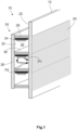
- FIG 1 an example of a lighting device 10 according to the prior art is shown using a basic and perspective illustration.
- the lighting device 10 comprises a surface element 12, which is incorporated into an external or internal cladding component 14 of a means of passenger and/or goods transport 16, in particular in motor vehicles 18 (cf. Figure 4 ), can be integrated.
- a surface element 12 which is incorporated into an external or internal cladding component 14 of a means of passenger and/or goods transport 16, in particular in motor vehicles 18 (cf. Figure 4 )
- the surface element 12 forms a visible side 20 that is visually perceptible to a viewer.
- the viewer is usually a passenger or a vehicle occupant located in the Interior of the passenger and/or goods transport means 16 is located.
- the visible side 20 is visually perceptible to every person who is in the immediate vicinity of the passenger and/or goods transport means 16.
- the side that lies opposite the visible side 20 should be referred to as the back 22 of the surface element 12.
- a support structure 24 is arranged on the back 22, which in the exemplary embodiment shown has a rear wall 26 and a total of four intermediate walls 28 arranged between the rear wall 26 and the surface element 12.
- the number of partitions 28 can be chosen largely freely, although it is advisable to provide at least two partitions 28. While the rear wall 26 runs parallel to the surface element 12, the intermediate walls 28 run perpendicular to this. Due to this arrangement, a total of three cavities 30 are created in the example shown.
- the surface of the rear wall 26 facing the surface element 12 is designed as a light-reflecting surface 32.
- the light-reflecting surface 32 can be designed in the manner of a mirror. Alternatively, it can be provided with a light, in particular white, coating, which is preferably particularly smooth.
- a light source 34 is arranged in each of the three cavities 30 in order to provide light in the respective cavities 30.
- the light source 34 is attached to the partition walls 28, in this case in the manner of ceiling lighting.
- the light source 34 is therefore located at the upper end of the cavities 30, although it is just as possible to arrange the light source 34 at the lower end of the cavities 30, so that the light source 34 is arranged in the cavity 30 in the manner of floor lighting.
- light source 34 When we talk about light source 34 below, this should not be understood to mean that only a single light source 34 is present. Rather, a large number of discrete light sources 34, for example a number of light-emitting diodes, can also be provided.
- the plurality of light sources 34 can be assigned to one or more groups of light sources 34.
- the light emitted by the light source 34 falls, on the one hand, directly onto the back 22 of the surface element 12 (beam path marked with arrow P1) and, on the other hand, onto the light-reflecting surface 32 (beam path marked with arrow P2).
- part of the light hits the surface 36 of the further intermediate wall 28 of the relevant cavity 30, which is opposite the light source 34.
- this side is not designed to be reflective, so that this part of the light is not examined in more detail and can be ignored.
- this surface 36 can also be designed to be reflective, so that the part of the light that hits this surface is also reflected to a considerable extent towards the surface element 12.
- the surface element 12 is at least partially translucent, so that at least a part of the light that hits the back 22, can pass through the surface element 12 and exit the surface element 12 again on the visible side 20.
- the visible side 20 is illuminated comparatively homogeneously. It can also be clearly seen that where the intermediate walls 28 and the back 22 of the surface element 12 rest against one another, darker sections are created on the visible side 20.
- lighting device 10 illuminates the visible side 20 more or less homogeneously, so that it is not possible to produce special lighting effects on the visible side 20. In particular, it is not possible to display patterns or logos on the visible side 20 in a visually perceptible manner.
- FIG. 2A and 2B a first exemplary embodiment of a lighting device 38 1 according to the invention is shown, wherein the Figure 2A the lighting device 38 1 analogous to that in the Figure 1 selected representation.
- Figure 2B shows a detail not enlarged to scale Figure 2A illustrated lighting device 38 1 according to the first exemplary embodiment.
- the basic structure of the lighting device 38 1 according to the first exemplary embodiment largely corresponds to that in Figure 1 illustrated lighting device 10, which is why only the essential differences will be discussed below.
- the lighting device 38 1 comprises a pattern-generating section 40, which is arranged on a support element 42 in the illustrated exemplary embodiment of the lighting device 38 1 according to the invention.
- the carrier element 42 comprises a first section which is triangular in cross section 44 and a second section which is approximately rectangular in cross section.
- the second section 46 in the Figure 2B For reasons of representation, it is shown significantly larger than is usually the case in reality. The second section 46 can also be omitted.
- the pattern-generating section 40 comprises a light-absorbing coating 48, which in the exemplary embodiment shown is applied to the light-reflecting surface 32, which has the structure already used for the in Figure 1 illustrated example can be the same as the light-reflecting surface 32 described, but according to the first exemplary embodiment of the lighting device 38 1 according to the invention extends to the pattern-generating section 40.
- the light-reflecting surface 32 is arranged on an intermediate layer 49 which is applied to the second section 46 of the carrier element 42.
- the intermediate layer 49 can be chosen so that the light-reflecting surface 32 can be easily manufactured and the light-absorbing coating 48 can be easily applied.
- the light-reflecting surface 32 also extends to the surface of the rear wall 26 facing the surface element 12, but this does not necessarily have to be the case.
- the light-absorbing coating 48 consists of a black finish.
- the pattern-generating section 40 can also have a light-scattering coating instead of or in addition to the light-absorbing coating 48, which is characterized in particular by a very rough surface.
- the light is affected in different ways: While the light that hits the light-reflecting surface 32 is reflected to a very large extent and directed, the light that hits the light-absorbing coating 48 is largely absorbed there, so that it is hardly reflected at all .
- the pattern-generating section 40 has a light-scattering coating, the light striking it is reflected in different directions.
- the carrier element 42 includes the first section 44, which is approximately triangular in cross section and with which the pattern-generating section 40 is attached to the carrier structure 24.
- the first section 44 of the support element 42 is fastened on the one hand to the rear wall 26 and on the other hand to one of the intermediate walls 28.
- the carrier element 42 is arranged so that it rests on that surface 36 of the intermediate wall 28 which is arranged opposite the light source 34.
- the pattern-generating section encloses an angle of approximately 45° with the intermediate wall 28 and the rear wall 26.
- the pattern-generating section 40 Due to the fact that the light striking the pattern-generating section 40 is reflected in different ways, a larger or smaller amount of light is reflected towards the surface element 12, so that sections with different brightness are generated on the visible side 20. As a result, a pattern appears on the visible side 20, which resembles a sine curve in the exemplary embodiment shown.
- FIG. 3A and 3B a second exemplary embodiment of the lighting device 38 2 according to the invention is shown, the selected representations being those of Figures 2A and 2B are equivalent to.
- the essential difference between the lighting device 38 1 according to the first exemplary embodiment and the lighting device 38 2 according to the second exemplary embodiment is that the pattern-generating section 40 not only has the light-absorbing coating 48 already mentioned for the first exemplary embodiment of the lighting device 38 1 according to the invention, but also also has a color-changing coating 50, which is applied to the intermediate layer 49.
- the pattern-generating section 40 does not include a light-reflecting surface 32.
- the light-reflecting surface 32 is limited to the rear wall 26.
- the light hits the color-changing coating 50, the light of a certain wavelength range is absorbed more strongly than the light of another wavelength range. As a result, the light reflected from the color-changing coating 50 has a different color than the light provided by the light source 34.
- the pattern resembling a sine curve is generated on the visible side 20 in both cases, but the two patterns differ in their colors.
- the light source 34 can be designed as a light-emitting diode which provides white light.
- the light source 34 can also be designed as an RGB LED 52, which usually comprises three light-emitting diodes, of which the first light-emitting diode provides red light, the second provides green light and the third provides blue light.
- the different LEDs of the RGB LED 52 can be selectively switched on and off, which can produce additional colors. The pattern created on the visible side 20 appears in correspondingly different colors.
- FIG 4 is a means of passenger and/or goods transport 16 based on a basic plan view, which is designed as a motor vehicle 18 and has a total of five of the lighting devices 38 according to the invention.
- Two of the lighting devices 38 are arranged in an external cladding component 14e, which is designed here as a bumper.
- a third of the lighting devices 38 is arranged in the tailgate 54 of the motor vehicle 18.
- the outer surface of the lighting device 38 forms part of the surface of the external cladding component 14e or the tailgate 54.
- the outer surface adjoins the surrounding surfaces of the motor vehicle 18 seamlessly or almost seamlessly.
- Two further lighting devices 38 according to the invention are each arranged on an internal trim component 14i, which serve as a door trim 56.
Landscapes
- Engineering & Computer Science (AREA)
- Mechanical Engineering (AREA)
- General Engineering & Computer Science (AREA)
- Arrangements Of Lighting Devices For Vehicle Interiors, Mounting And Supporting Thereof, Circuits Therefore (AREA)
Claims (7)
- Dispositif d'éclairage (38) pour un composant d'habillage (14) externe ou interne d'un moyen de transport de personnes et/ou de marchandises (16) comprenant :- un élément de surface (12) formant le composant d'habillage (14) ou intégré ou intégrable dans un composant d'habillage (14) externe ou interne d'un moyen de transport de personnes et/ou de marchandise (16), et qui forme au moins un segment du côté visible (20) du composant d'habillage (14) et qui est au moins partiellement transparent à la lumière,- une structure portante (24) installée au dos (22) à l'opposé du côté visible (20) de l'élément de surface (12) et ayant au moins une surface photo-réfléchissante (32),- au moins une source lumineuse (34) pour fournir la lumière dans le dispositif d'éclairage (38),* la surface photo-réfléchissante (32) et la source lumineuse (34) sont réalisées et installées pour que la lumière soit réfléchie par la surface réfléchissante (32) vers l'élément de surface (12) et soit perceptible visuellement sur le côté visible (20), et- au moins un segment (40) générant un motif qui,caractérisé en ce que* est installé sur un élément porteur (42) relié à la structure portante (24), et* la lumière notamment pour la luminosité et/ou la couleur est réfléchie vers l'élément de surface (12) pour rendre perceptible visuellement un motif sur le côté visible (20),la surface photo-réfléchissante (32) est sur le segment (40) générant le motif, oucaractérisé en ce quela surface photo-réfléchissante (32) s'étend sur le segment (40) générant le motif, oucaractérisé en ce quele segment (40) générant le motif ne comporte pas de surface photoréfléchissante (32) et le segment (40) générant le motif a un revêtement de couleur changeante (50) pour changer la couleur de la lumière réfléchie.
- Dispositif d'éclairage (38) selon la revendication 1,
caractérisé en ce que
le segment (40) générant le motif comprend un revêtement (48) absorbant la lumière ou diffusant la lumière. - Dispositif d'éclairage (38) selon l'une des revendications précédentes,
caractérisé en ce que
au cas où la surface photo-réfléchissante (32) est sur le segment (40) générant le motif ou s'étend sur le segment (40) générant le motif, ce segment (40) générant le motif a un revêtement (50) changeant la couleur pour modifier la couleur de la lumière réfléchie. - Dispositif d'éclairage (38) selon l'une des revendications précédentes,
caractérisé en ce que
au moins la source lumineuse (34) est fixée à la structure portante (24). - Dispositif d'éclairage (38) selon l'une des revendications précédentes,
caractérisé en ce que
la source lumineuse (34) comprend au moins une Led-RGB (52). - Composant d'habillage (14) externe ou interne pour un moyen de transport de personnes et/ou de marchandises (16) comprenant au moins un dispositif d'éclairage (38) selon l'une des revendications précédentes.
- Moyen de transport de personnes et/ou de marchandises (16) comprenant au moins un composant d'habillage (14) externe et/ou interne selon la revendication 6 et/ou au moins un dispositif d'éclairage (38) selon l'une des revendications 1 à 5.
Priority Applications (1)
| Application Number | Priority Date | Filing Date | Title |
|---|---|---|---|
| EP19193663.2A EP3786930B1 (fr) | 2019-08-27 | 2019-08-27 | Dispositif d'éclairage pour un composant de revêtement ou comportant un composant de revêtement externe ou interne d'un moyen de transport de personnes et / ou de marchandises, composant de revêtement doté d'un tel dispositif d'éclairage ainsi que moyen de transport des personnes et / ou des marchandises comportant au moins un tel composant de revêtement externe ou interne |
Applications Claiming Priority (1)
| Application Number | Priority Date | Filing Date | Title |
|---|---|---|---|
| EP19193663.2A EP3786930B1 (fr) | 2019-08-27 | 2019-08-27 | Dispositif d'éclairage pour un composant de revêtement ou comportant un composant de revêtement externe ou interne d'un moyen de transport de personnes et / ou de marchandises, composant de revêtement doté d'un tel dispositif d'éclairage ainsi que moyen de transport des personnes et / ou des marchandises comportant au moins un tel composant de revêtement externe ou interne |
Publications (2)
| Publication Number | Publication Date |
|---|---|
| EP3786930A1 EP3786930A1 (fr) | 2021-03-03 |
| EP3786930B1 true EP3786930B1 (fr) | 2023-12-27 |
Family
ID=67770377
Family Applications (1)
| Application Number | Title | Priority Date | Filing Date |
|---|---|---|---|
| EP19193663.2A Active EP3786930B1 (fr) | 2019-08-27 | 2019-08-27 | Dispositif d'éclairage pour un composant de revêtement ou comportant un composant de revêtement externe ou interne d'un moyen de transport de personnes et / ou de marchandises, composant de revêtement doté d'un tel dispositif d'éclairage ainsi que moyen de transport des personnes et / ou des marchandises comportant au moins un tel composant de revêtement externe ou interne |
Country Status (1)
| Country | Link |
|---|---|
| EP (1) | EP3786930B1 (fr) |
Family Cites Families (7)
| Publication number | Priority date | Publication date | Assignee | Title |
|---|---|---|---|---|
| JPS6253262A (ja) * | 1985-08-30 | 1987-03-07 | Hashimoto Forming Co Ltd | 装飾成形品 |
| JP4542727B2 (ja) * | 2001-08-13 | 2010-09-15 | 帝人化成株式会社 | 高意匠性シート状積層構造体およびその利用 |
| DE102004009925A1 (de) * | 2004-03-02 | 2005-09-22 | Volkswagen Ag | Reflektor für eine Fahrzeugleuchtvorrichtung |
| DE102008038442A1 (de) * | 2008-08-20 | 2010-02-25 | Trw Automotive Safety Systems Gmbh | Fahrzeuglenkrad |
| DE102010031938A1 (de) * | 2010-07-22 | 2012-01-26 | Daimler Ag | Verkleidungsteil eines Kraftfahrzeugs |
| DE102012105412A1 (de) * | 2012-06-21 | 2013-12-24 | International Automotive Components Group Gmbh | Beleuchtbares Verkleidungsbauteil für ein Fahrzeug und Verfahren zu dessen Herstellung |
| DE202018104438U1 (de) * | 2018-08-01 | 2019-08-06 | Novem Car Interior Design Gmbh | Formteil |
-
2019
- 2019-08-27 EP EP19193663.2A patent/EP3786930B1/fr active Active
Also Published As
| Publication number | Publication date |
|---|---|
| EP3786930A1 (fr) | 2021-03-03 |
Similar Documents
| Publication | Publication Date | Title |
|---|---|---|
| DE102016009660B4 (de) | Beleuchtetes Zierteil | |
| EP3452327B1 (fr) | Ensemble commutateur avec éclairage pour un véhicule à moteur, véhicule à moteur et procédé pour produire un ensemble commutateur avec éclairage | |
| DE102014202774B4 (de) | Deckenverkleidungselement für eine Innenverkleidungsanordnung einer Flugzeugkabine | |
| DE102016115258A1 (de) | Nahtloses Kombiinstrument | |
| DE102019131711A1 (de) | Beleuchtungsvorrichtung für ein Kraftfahrzeug | |
| EP2152544B1 (fr) | Dispositif d'éclairage conçu pour éclairer l'espace intérieur d'un véhicule | |
| EP3347275B1 (fr) | Marquage du chemin d'évacuation pour avions | |
| DE102014202753A1 (de) | Flugzeugkabinenanordnung | |
| DE102017105480A1 (de) | Seitenabdeckung für den Übergang zwischen zwei beweglich miteinander verbundenen Fahrzeugteilen | |
| EP4113001A1 (fr) | Module d'éclairage pour dispositif d'éclairage d'un véhicule et procédé de réduction d'une désaturation de la couleur dans un module d'éclairage pour un dispositif d'éclairage d'un véhicule | |
| EP3786930B1 (fr) | Dispositif d'éclairage pour un composant de revêtement ou comportant un composant de revêtement externe ou interne d'un moyen de transport de personnes et / ou de marchandises, composant de revêtement doté d'un tel dispositif d'éclairage ainsi que moyen de transport des personnes et / ou des marchandises comportant au moins un tel composant de revêtement externe ou interne | |
| DE102014202751B4 (de) | Innenverkleidungsanordnung für eine Passagierkabine eines Fahrzeugs | |
| WO2020104126A1 (fr) | Feu pour véhicule à moteur | |
| EP2709088B1 (fr) | Eclairage | |
| DE102016216276B4 (de) | Innenraumverkleidung für ein Kraftfahrzeug | |
| DE102017124311A1 (de) | Leuchtvorrichtung | |
| DE102014010310B3 (de) | Beleuchtetes Zeigerinstrument für ein Kraftfahrzeug | |
| DE202021103689U1 (de) | Optisches Innenausstattungsbauteil, Innenausstattungssystem und Verkehrsmittel | |
| DE202013011362U1 (de) | Vorrichtung zur Aufnahme einer Vielzahl von Lichtleitfasern | |
| DE102019001952A1 (de) | Anordnung zur Darstellung einer Abbildung | |
| DE102018219116A1 (de) | Kraftfahrzeug mit versteckten Lichtfunktionen | |
| DE102017215892A1 (de) | Beleuchtungseinrichtung für ein Fahrzeug | |
| DE102018102331A1 (de) | Innenraumbeleuchtungseinrichtung für ein Kraftfahrzeug | |
| DE102020206720A1 (de) | Kabinenanordnung für einen Flugzeuginnenraum eines Flugzeugs, Verschalungseinrichtung für eine Kabinenanordnung sowie Verfahren zur Installation dieser | |
| DE10108073A1 (de) | Leuchtvorrichtung |
Legal Events
| Date | Code | Title | Description |
|---|---|---|---|
| PUAI | Public reference made under article 153(3) epc to a published international application that has entered the european phase |
Free format text: ORIGINAL CODE: 0009012 |
|
| STAA | Information on the status of an ep patent application or granted ep patent |
Free format text: STATUS: THE APPLICATION HAS BEEN PUBLISHED |
|
| AK | Designated contracting states |
Kind code of ref document: A1 Designated state(s): AL AT BE BG CH CY CZ DE DK EE ES FI FR GB GR HR HU IE IS IT LI LT LU LV MC MK MT NL NO PL PT RO RS SE SI SK SM TR |
|
| AX | Request for extension of the european patent |
Extension state: BA ME |
|
| STAA | Information on the status of an ep patent application or granted ep patent |
Free format text: STATUS: REQUEST FOR EXAMINATION WAS MADE |
|
| 17P | Request for examination filed |
Effective date: 20210701 |
|
| RBV | Designated contracting states (corrected) |
Designated state(s): AL AT BE BG CH CY CZ DE DK EE ES FI FR GB GR HR HU IE IS IT LI LT LU LV MC MK MT NL NO PL PT RO RS SE SI SK SM TR |
|
| RAP3 | Party data changed (applicant data changed or rights of an application transferred) |
Owner name: MOTHERSON INNOVATIONS COMPANY LIMITED |
|
| STAA | Information on the status of an ep patent application or granted ep patent |
Free format text: STATUS: EXAMINATION IS IN PROGRESS |
|
| 17Q | First examination report despatched |
Effective date: 20220705 |
|
| GRAP | Despatch of communication of intention to grant a patent |
Free format text: ORIGINAL CODE: EPIDOSNIGR1 |
|
| STAA | Information on the status of an ep patent application or granted ep patent |
Free format text: STATUS: GRANT OF PATENT IS INTENDED |
|
| INTG | Intention to grant announced |
Effective date: 20230331 |
|
| P01 | Opt-out of the competence of the unified patent court (upc) registered |
Effective date: 20230427 |
|
| GRAJ | Information related to disapproval of communication of intention to grant by the applicant or resumption of examination proceedings by the epo deleted |
Free format text: ORIGINAL CODE: EPIDOSDIGR1 |
|
| STAA | Information on the status of an ep patent application or granted ep patent |
Free format text: STATUS: EXAMINATION IS IN PROGRESS |
|
| INTC | Intention to grant announced (deleted) | ||
| GRAP | Despatch of communication of intention to grant a patent |
Free format text: ORIGINAL CODE: EPIDOSNIGR1 |
|
| STAA | Information on the status of an ep patent application or granted ep patent |
Free format text: STATUS: GRANT OF PATENT IS INTENDED |
|
| INTG | Intention to grant announced |
Effective date: 20230804 |
|
| GRAS | Grant fee paid |
Free format text: ORIGINAL CODE: EPIDOSNIGR3 |
|
| GRAA | (expected) grant |
Free format text: ORIGINAL CODE: 0009210 |
|
| STAA | Information on the status of an ep patent application or granted ep patent |
Free format text: STATUS: THE PATENT HAS BEEN GRANTED |
|
| AK | Designated contracting states |
Kind code of ref document: B1 Designated state(s): AL AT BE BG CH CY CZ DE DK EE ES FI FR GB GR HR HU IE IS IT LI LT LU LV MC MK MT NL NO PL PT RO RS SE SI SK SM TR |
|
| REG | Reference to a national code |
Ref country code: GB Ref legal event code: FG4D Free format text: NOT ENGLISH |
|
| REG | Reference to a national code |
Ref country code: CH Ref legal event code: EP |
|
| REG | Reference to a national code |
Ref country code: DE Ref legal event code: R096 Ref document number: 502019010214 Country of ref document: DE |
|
| REG | Reference to a national code |
Ref country code: IE Ref legal event code: FG4D Free format text: LANGUAGE OF EP DOCUMENT: GERMAN |
|
| PG25 | Lapsed in a contracting state [announced via postgrant information from national office to epo] |
Ref country code: GR Free format text: LAPSE BECAUSE OF FAILURE TO SUBMIT A TRANSLATION OF THE DESCRIPTION OR TO PAY THE FEE WITHIN THE PRESCRIBED TIME-LIMIT Effective date: 20240328 |
|
| REG | Reference to a national code |
Ref country code: LT Ref legal event code: MG9D |
|
| PG25 | Lapsed in a contracting state [announced via postgrant information from national office to epo] |
Ref country code: LT Free format text: LAPSE BECAUSE OF FAILURE TO SUBMIT A TRANSLATION OF THE DESCRIPTION OR TO PAY THE FEE WITHIN THE PRESCRIBED TIME-LIMIT Effective date: 20231227 |
|
| PG25 | Lapsed in a contracting state [announced via postgrant information from national office to epo] |
Ref country code: LT Free format text: LAPSE BECAUSE OF FAILURE TO SUBMIT A TRANSLATION OF THE DESCRIPTION OR TO PAY THE FEE WITHIN THE PRESCRIBED TIME-LIMIT Effective date: 20231227 Ref country code: GR Free format text: LAPSE BECAUSE OF FAILURE TO SUBMIT A TRANSLATION OF THE DESCRIPTION OR TO PAY THE FEE WITHIN THE PRESCRIBED TIME-LIMIT Effective date: 20240328 Ref country code: FI Free format text: LAPSE BECAUSE OF FAILURE TO SUBMIT A TRANSLATION OF THE DESCRIPTION OR TO PAY THE FEE WITHIN THE PRESCRIBED TIME-LIMIT Effective date: 20231227 Ref country code: BG Free format text: LAPSE BECAUSE OF FAILURE TO SUBMIT A TRANSLATION OF THE DESCRIPTION OR TO PAY THE FEE WITHIN THE PRESCRIBED TIME-LIMIT Effective date: 20240327 |
|
| REG | Reference to a national code |
Ref country code: NL Ref legal event code: MP Effective date: 20231227 |