EP3784615B1 - Hebewerkzeug - Google Patents
Hebewerkzeug Download PDFInfo
- Publication number
- EP3784615B1 EP3784615B1 EP19726189.4A EP19726189A EP3784615B1 EP 3784615 B1 EP3784615 B1 EP 3784615B1 EP 19726189 A EP19726189 A EP 19726189A EP 3784615 B1 EP3784615 B1 EP 3784615B1
- Authority
- EP
- European Patent Office
- Prior art keywords
- lifting tool
- frame
- centreline
- lifting
- hoisting member
- Prior art date
- Legal status (The legal status is an assumption and is not a legal conclusion. Google has not performed a legal analysis and makes no representation as to the accuracy of the status listed.)
- Active
Links
Images


Classifications
-
- B—PERFORMING OPERATIONS; TRANSPORTING
- B66—HOISTING; LIFTING; HAULING
- B66C—CRANES; LOAD-ENGAGING ELEMENTS OR DEVICES FOR CRANES, CAPSTANS, WINCHES, OR TACKLES
- B66C1/00—Load-engaging elements or devices attached to lifting or lowering gear of cranes or adapted for connection therewith for transmitting lifting forces to articles or groups of articles
- B66C1/10—Load-engaging elements or devices attached to lifting or lowering gear of cranes or adapted for connection therewith for transmitting lifting forces to articles or groups of articles by mechanical means
- B66C1/108—Load-engaging elements or devices attached to lifting or lowering gear of cranes or adapted for connection therewith for transmitting lifting forces to articles or groups of articles by mechanical means for lifting parts of wind turbines
-
- B—PERFORMING OPERATIONS; TRANSPORTING
- B66—HOISTING; LIFTING; HAULING
- B66C—CRANES; LOAD-ENGAGING ELEMENTS OR DEVICES FOR CRANES, CAPSTANS, WINCHES, OR TACKLES
- B66C1/00—Load-engaging elements or devices attached to lifting or lowering gear of cranes or adapted for connection therewith for transmitting lifting forces to articles or groups of articles
- B66C1/10—Load-engaging elements or devices attached to lifting or lowering gear of cranes or adapted for connection therewith for transmitting lifting forces to articles or groups of articles by mechanical means
- B66C1/42—Gripping members engaging only the external or internal surfaces of the articles
- B66C1/44—Gripping members engaging only the external or internal surfaces of the articles and applying frictional forces
- B66C1/54—Internally-expanding grippers for handling hollow articles
-
- Y—GENERAL TAGGING OF NEW TECHNOLOGICAL DEVELOPMENTS; GENERAL TAGGING OF CROSS-SECTIONAL TECHNOLOGIES SPANNING OVER SEVERAL SECTIONS OF THE IPC; TECHNICAL SUBJECTS COVERED BY FORMER USPC CROSS-REFERENCE ART COLLECTIONS [XRACs] AND DIGESTS
- Y02—TECHNOLOGIES OR APPLICATIONS FOR MITIGATION OR ADAPTATION AGAINST CLIMATE CHANGE
- Y02E—REDUCTION OF GREENHOUSE GAS [GHG] EMISSIONS, RELATED TO ENERGY GENERATION, TRANSMISSION OR DISTRIBUTION
- Y02E10/00—Energy generation through renewable energy sources
- Y02E10/70—Wind energy
- Y02E10/72—Wind turbines with rotation axis in wind direction
-
- Y—GENERAL TAGGING OF NEW TECHNOLOGICAL DEVELOPMENTS; GENERAL TAGGING OF CROSS-SECTIONAL TECHNOLOGIES SPANNING OVER SEVERAL SECTIONS OF THE IPC; TECHNICAL SUBJECTS COVERED BY FORMER USPC CROSS-REFERENCE ART COLLECTIONS [XRACs] AND DIGESTS
- Y02—TECHNOLOGIES OR APPLICATIONS FOR MITIGATION OR ADAPTATION AGAINST CLIMATE CHANGE
- Y02E—REDUCTION OF GREENHOUSE GAS [GHG] EMISSIONS, RELATED TO ENERGY GENERATION, TRANSMISSION OR DISTRIBUTION
- Y02E10/00—Energy generation through renewable energy sources
- Y02E10/70—Wind energy
- Y02E10/727—Offshore wind turbines
Definitions
- the present invention relates to a lifting tool for lifting an element of an offshore structure, such as a transition piece of an offshore wind turbine.
- Transition pieces are being lifted by connecting a lifting tool to a hoisting cable of a crane, on the one hand, and to the transition piece, on the other hand. It is important to align the lifting tool with the centre of gravity of the transition piece. Otherwise the transition piece may suspend inclined from the hoisting cable of a crane and/or the transition piece may start swinging upon lifting it. The same effect may happen with other elements to be lifted.
- DE 10 2011 011603 is related to a device which has an annular front end provided with an inwardly protruding annular flange.
- Two arms are aligned above the front end to a to-be lifted component radial to the front end.
- the arms support grippers moved between a retracted state and an extended state.
- the grippers are moved through an opening of the front end limited by the flange in the retracted state.
- the grippers are engaged behind the flange at an underside of the device in the extended state.
- the grippers are moved in a direction parallel to a longitudinal center axis of the arms.
- the present invention aims to provide a lifting tool which can be quickly and accurately aligned with the centre of gravity of an element to be lifted.
- the lifting tool comprises a frame, a plurality of engagement members for engaging an element to be lifted, which engagement members are mounted to the frame at an angular distance from each other about a centreline of the frame, a hoisting member to be connected to a hoisting cable of a crane, and located within a virtual cylinder on which the engagement members lie, wherein the hoisting member and the frame are interconnected rigidly through at least three linear actuators which are arranged such that the hoisting member is movable with respect to the frame in a plurality of radial directions with respect to the centreline, independently from the engagement members.
- An advantage of the invention is that the position of the hoisting member can be adjusted with respect to the frame in different radial directions.
- the invention provides the opportunity to control the alignment in an automatic way by operating the individual linear actuators. This works quickly and is also safe since operators can stay away from the lifting tool upon aligning the lifting tool.
- the lifting tool may be provided with sensors to measure acceleration/motion, position, gravity, vibration, pressure, etc. in order to facilitate automatically aligning and positioning in horizontal and vertical direction.
- the relative position of the hoisting member may be adjusted before starting a hoisting action on the basis of a calculated or measured centre of gravity of an element to be lifted.
- the rigid interconnection allows to guide a pushing force between the frame and the hoisting member, which is different from a cable connection, for example, which cannot guide a pushing force.
- the centreline of the frame is directed upwardly or substantially vertical and the engagement members may lie in a horizontally oriented plane.
- the centreline of the frame may coincide with a centreline of the virtual cylinder.
- the actuators are coupled to the frame at the engagement members in order to minimize any distance between an engagement member and a location of the frame on which a hoisting force is exerted.
- the hoisting member may be located above the frame under operating conditions of the lifting tool.
- the hoisting member and the frame are interconnected through three linear actuators which are positioned at equiangular distance about the hoisting member when the hoisting member is located at the centreline. This arrangement provides the opportunity to move the hoisting member in all radial directions with respect to the centreline, which avoids the need to position the lifting tool at a predetermined rotational position with respect to the element to be lifted.
- Each of the linear actuators may be pivotally mounted to the hoisting member through a first pivot and pivotally mounted to the frame through a second pivot.
- each of the linear actuators extends substantially perpendicular to the centreline, wherein the first pivot and the second pivot have respective pivot axes which extend substantially parallel to the centreline.
- the linear actuators may form a tripod.
- a hexapod structure may be conceivable, as well.
- linear actuators may comprise hydraulic cylinders.
- the engagement members may be provided with respective supporting elements including upwardly directed supporting surfaces for engaging cooperating lifting plates of an element to be lifted, wherein the frame is provided with a driving device for rotating the lifting tool with respect to an element to be lifted so as to move the supporting elements to a position below the lifting plates.
- the supporting elements of the lifting tool and the lifting plates of an element to be lifted form a bayonet coupling.
- the driving device may be formed by a drivable driving wheel which is movable in radial direction of the centreline in order to engage and disengage the driving wheel to and from a tube of the element to be lifted when the element to be lifted is provided with a tubular portion.
- the supporting elements may be directed to the centreline of the frame such that they can engage outwardly directed lifting plates of an element to be lifted.
- outwardly directed lifting plates are advantageous when the element to be lifted is a transition piece of an offshore wind turbine, for example, since the upper side of a transition piece is often provided with a protection lid for temporarily protecting devices in the transition piece. When outwardly directed lifting plates are applied the protection lid can stay on the transition piece during a hoisting action.
- the lifting tool may be provided with an alignment apparatus, which comprises a camera that is positioned such that a view line of the camera extends in the same direction as the centreline of the frame, and a control device for receiving and processing a signal from the camera, which is configured such that, when a transition piece is to be mounted to a monopile by the lifting tool and the transition piece approaches the monopile, the control device determines at least two circumferential images of the monopile along its length on the basis of the camera signal, for example an upper edge and a lower edge of the monopile, and respective imaginary circumferential images having fixed positions at different locations along the view line of the camera and shows the images to an operator via a user interface.
- the operator may be a crane driver who does not have direct view on the monopile.
- the crane driver can move the lifting tool including the transition piece such that the circumferential images of the monopile and the imaging circumferential images are moved to each other in order to align the transition piece and the monopile.
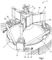
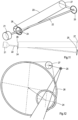
- Fig. 1 shows an embodiment of a lifting tool 1 according to the invention.
- the lifting tool 1 is suitable for lifting an element of an offshore structure, such as a transition piece 2 of a wind turbine, or lifting another elongated member including a flange.
- the transition piece 2 comprises a tubular element 3 which can be mounted onto a monopile that is fixed to the sea bottom, for example.
- the transition piece 2 is provided with a working platform 4 that is fixed to the tubular element 3.
- the tubular element 3 has an upper end which is covered by a protection lid 5 for temporarily protecting devices (not shown) in the tubular element 3.
- Such devices are intended for use during the operational time of a wind turbine and are already placed inside the transition piece 2 before it is actually placed off shore.
- the element to be lifted is a tubular element which comprises a removable protection lid for closing the tubular element.
- the lifting tool 1 is provided with three engagement members 6 which can engage lifting plates 7 that are fixed to the upper end of the tubular element 3.
- the engagement members 6 and the lifting plates 7 are coupled to each other via a bayonet coupling in this case.
- the lifting plates 7 project in outward direction from the transition piece 2. This means that the protection lid 5 can stay on the transition piece 2 during a hoisting action.
- Fig. 2 shows the lifting tool 1 in more detail.
- the lifting tool 1 comprises a frame 8 to which the engagement members 6 are mounted.
- the frame 8 lies in a main plane which is oriented horizontally under operating conditions.
- the engagement members 6 are located on a virtual cylinder which has a centreline perpendicular to the horizontally oriented main plane of the frame 8.
- the lifting tool 1 is also provided with a hoisting member 9 that can be connected to a hoisting cable of a crane (not shown) via a hoisting eye in the hoisting member 9.
- the hoisting member 9 is located above the frame 8 under operating conditions of the lifting tool 1.
- the hoisting member 9 and the frame 8 are interconnected through three linear actuators in the form of hydraulic cylinders 10 which are pivotally mounted to the hoisting member 9 via respective first pivots 11 including respective pivot axes that extend perpendicular to the main plane of the frame 8.
- the hydraulic cylinders 10 extend perpendicular to the centreline of the virtual cylinder and form a rigid connection between the hoisting member 9 and the frame 8.
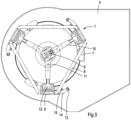
- the first pivots 11 are located at equiangular distance about the hoisting member 9.
- the hydraulic cylinders 10 extend radially from the hoisting member 9 at equiangular distance about the hoisting member 9. This condition is shown from above in Fig. 3 .
- the hydraulic cylinders 10 are also pivotally mounted to the frame 8 via respective second pivots 12 including respective pivot axes that extend parallel to the pivot axes of the first pivots 11.
- the second pivots 12 are located at the engagement members 6. Due to the arrangement of the hydraulic cylinders 10 with respect to the hoisting member 9 and the frame 8 the hoisting member 9 is movable with respect to the frame 8 in all radial directions of the centreline of the virtual cylinder, independent from the engagement members 6. This provides the opportunity to easily move the hoisting member 9 to a location above the centre of gravity of the transition piece 2 before lifting it.
- the lifting tool 1 is provided with driving wheels 13, which are mounted to arms 14 that are pivotally mounted to the frame 8 at the engagement members 6.
- the arms 14 are driven by hydraulic cylinders 15 such that the driving wheels 13 can be moved to and from the tubular element 3 of the transition piece 2.
- Fig. 4 which illustrates that the frame 8 has rotated clockwise with respect to the situation as shown in Fig. 3 .
- respective upwardly directed supporting surfaces 16 of the engagement members 6 are positioned below the lifting plates 7, hence forming a bayonet coupling. This condition is shown in Fig. 6 .
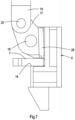
- Figs. 7 and 8 show the operation of the engagement members 6 in more detail.
- Each of the engagement members 6 is provided with an arm 17 that is pivotally mounted to the frame 8 via a third pivot 18 that has a horizontally oriented pivot axis, on the one hand, and that is pivotally mounted to a vertical shaft 19 of the second pivot 12 via a fourth pivot 20 that also has a horizontally oriented pivot axis, on the other hand.
- the pivot axes of the fourth pivots 20 lie closer to the hoisting member 9 than the pivot axes of the third pivots 18.
- Each of the arms 17 is provided with a locking element 28.
- each of the arms 17 is adapted such that it can rotate through the corresponding third pivot 18 by only a limited angle due to abutment of a side of the locking element 28 against an opposite wall at the engagement member 6.
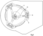
- Fig. 5 shows a situation in which the hoisting member 9 is moved with respect to the frame 8, away from the centreline of the virtual cylinder by operating the individual hydraulic cylinders 10.
- the relative position of the hoisting member 9 may be adjusted before starting a hoisting action on the basis of a calculated or measured centre of gravity of the transition piece 2.
- the relative position of the hoisting member 9 may be adjusted during a hoisting action on the basis of information from sensors on the lifting tool 1 and/or the transition piece 2.
- the hydraulic cylinders may form a tripod.
- Figs. 9 and 10 show a hydraulic circuit of a tripod configuration, in which two of three hydraulic cylinders 10 are visible.
- Fig. 9 illustrates a condition in which the hoisting member 9 is located at the centreline of the frame 8, which is out of line with the centre of gravity COG of the transition piece 2.
- Fig. 10 illustrates a condition in which the hydraulic cylinders 10 are operated such that the hoisting member 9 is aligned with the centre of gravity COG.
- each cylinder 10 is connected to each other in order to use the principle of communicating volumes to distribute the oil pressure in the cylinders 10. All three cylinders 10 are identical and are equipped with brakes and double seals in order to make them fail safe. Furthermore, each cylinder 10 has a system for releasing the pressure in order to enable soft landing of the lifting tool 1.
- the hydraulic lines between the cylinders 10 contain valves to enable or disable the flow of oil through the system depending on the required orientation (angle) the transition piece 2 needs to be lifted.
- the lifting tool 1 may be provided with an alignment apparatus including a camera 21 and a control device (not shown).
- Fig. 11 illustrates the functioning of the alignment apparatus.
- the camera 21 may be located on the frame 8 of the lifting tool 1. It is positioned such that a view line 22 of the camera 21 extends in the same direction as the centreline of the frame 8.
- Fig. 11 only illustrates the functioning of the camera 21 and the control device in general without showing the lifting tool 1, the transition piece 2 and the monopile, but a tube 23 in Fig. 11 may be considered as being a monopile.
- Fig. 11 shows that along the view line 22 of the camera 21 there are a front imaginary circumferential image 24 and a rear imaginary circumferential image 25.
- Both front and rear imaginary circumferential images 24, 25 have different positions along the view line 22 and are generated by the control device.
- the camera 21 detects a front circumferential image 26 and a rear circumferential image 27 of the monopile.
- the front and rear circumferential images 26, 27 may correspond to an upper rim and a lower rim of the monopile, but other locations along the tube 23 are conceivable.
- the control device shows the detected and generated images 24-27 to a crane driver via a user interface (not shown), for example a mobile phone.
- Fig. 12 shows an example of the images as can be seen by the crane driver.
- the crane driver can adjust the position and orientation of the transition piece 2 such that the front imaginary circumferential image 24 and the front circumferential image 26, on the one hand, and the rear imaginary circumferential image 25 and the rear circumferential image 27, on the other hand, form concentric circles, such that the transition piece 2 and the monopile are aligned.
- the monopile or tube 23 have circular cross sections, hence resulting in concentric circles, but alternative shapes are conceivable.
- the control device may be provided with software for calculating the required movements needed by the crane driver in order to facilitate to obtain concentricity of the images. Since the crane driver can align the transition piece 2 and the monopile without the necessity of human assistance at the monopile the work can be done in a safe way.
- the invention is also related to a method of aligning a member, for example a lifting tool, with respect to an elongated element, for example a monopile, wherein a camera is mounted to the member to be aligned, wherein the camera is positioned such that its view extends along a view line that, after aligning, substantially coincides with a centreline of the elongated member, wherein the member including the camera is located at a position at or close to an end of the elongated element in which position the elongated element is visible by the camera, such that the camera detects at least two circumferential images of the elongated element located at different locations in longitudinal direction thereof, for example an upper rim and a lower rim of the elongated element, wherein at least two imaginary circumferential images at different positions along the view line of the camera are generated, wherein the member to be aligned and the elongated element are displaced and oriented with respect to each other such that the centres of the imaginary circumferential images substantially coincide with
Landscapes
- Engineering & Computer Science (AREA)
- Mechanical Engineering (AREA)
- Load-Engaging Elements For Cranes (AREA)
Claims (13)
- Hebewerkzeug (1) zum Anheben eines Elements einer Offshore-Struktur, wie beispielsweise eines Übergangsstücks (2) einer Offshore-Windturbine, das einen Rahmen (8), mehrere Eingriffselemente (6) zum Eingreifen mit einem anzuhebenden Element (2), wobei die Eingriffselemente (6) am Rahmen (8) in einem Winkelabstand voneinander um eine Mittellinie des Rahmens (8) herum angebracht sind, und ein Hubelement (9) aufweist, das mit einem Hubseil eines Krans zu verbinden ist, und innerhalb eines virtuellen Zylinders angeordnet ist, auf dem die Eingriffselemente (6) liegen, dadurch gekennzeichnet, dass das Hubelement (9) und der Rahmen (8) starr durch mindestens drei lineare Aktuatoren (10) miteinander verbunden sind, die so angeordnet sind, dass das Hubelement (9) in Bezug auf den Rahmen (8) in mehreren radialen Richtungen in Bezug auf die Mittellinie unabhängig von den Eingriffselementen (6) beweglich ist.
- Hebewerkzeug (1) nach Anspruch 1, wobei die Aktuatoren (10) an den Eingriffselementen (6) mit dem Rahmen (8) gekoppelt sind.
- Hebewerkzeug (1) nach Anspruch 1 oder 2, wobei das Hubelement (9) unter Betriebsbedingungen des Hebewerkzeugs (1) über dem Rahmen (8) angeordnet ist.
- Hebewerkzeug (1) nach einem der vorhergehenden Ansprüche, wobei das Hubelement (9) und der Rahmen (8) durch drei lineare Aktuatoren (10) miteinander verbunden sind, die in gleichem Winkelabstand um das Hubelement (9) angeordnet sind, wenn sich das Hubelement (9) auf der Mittellinie befindet.
- Hebewerkzeug (1) nach Anspruch 4, wobei jeder der linearen Aktuatoren (10) über einen ersten Drehpunkt (11) drehbar am Hubelement (9) und über einen zweiten Drehpunkt (12) drehbar am Rahmen (8) angebracht ist.
- Hebewerkzeug (1) nach Anspruch 5, wobei sich jeder der linearen Aktuatoren (10) im Wesentlichen senkrecht zur Mittellinie erstreckt, wobei der erste Drehpunkt (11) und der zweite Drehpunkt (12) jeweilige Drehachsen aufweisen, die sich im Wesentlichen parallel zur Mittellinie erstrecken.
- Hebewerkzeug (1) nach Anspruch 4 oder 5, wobei die linearen Aktuatoren ein Dreibein bilden.
- Hebewerkzeug (1) nach einem der vorhergehenden Ansprüche, wobei die linearen Aktuatoren Hydraulikzylinder (10) aufweisen.
- Hebewerkzeug (1) nach einem der vorangehenden Ansprüche, wobei die Eingriffselemente (6) mit jeweiligen Stützelementen versehen sind, die nach oben gerichtete Stützflächen (16) zum Eingreifen mit zusammenwirkenden Hebeplatten (7) eines anzuhebenden Elements (2) aufweisen, wobei der Rahmen (8) mit einer Antriebsvorrichtung (13) zum Drehen des Hebewerkzeugs (1) in Bezug auf ein anzuhebendes Element (2) versehen ist, um die Stützelemente in eine Position unterhalb der Hebeplatten (7) zu bewegen.
- Hebewerkzeug (1) nach Anspruch 9, wobei die Antriebsvorrichtung durch ein antreibbares Antriebsrad (13) gebildet wird, das in radialer Richtung der Mittellinie beweglich ist.
- Hebewerkzeug (1) nach Anspruch 9 oder 10, wobei die Stützelemente zur Mittellinie des Rahmens (8) gerichtet sind.
- Hebewerkzeug (1) nach einem der vorhergehenden Ansprüche, wobei das Hebewerkzeug (1) mit einer Ausrichtvorrichtung versehen ist, die eine Kamera (21), die so positioniert ist, dass eine Sichtlinie (22) der Kamera (21) in der gleichen Richtung wie die Mittellinie des Rahmens (8) verläuft, und eine Steuervorrichtung zum Empfangen und Verarbeiten eines Signals von der Kamera aufweist, die so konfiguriert ist, dass, wenn ein Übergangsstück (2) durch das Hebewerkzeug (1) an einem Monopile montiert werden soll und das Übergangsstück (2) sich dem Monopile nähert, die Steuervorrichtung anhand des Kamerasignals mindestens zwei Umfangsbilder (26, 27) des Monopiles entlang seiner Länge, beispielsweise eine Oberkante und eine Unterkante des Monopiles, ermittelt und jeweils imaginäre Umfangsbilder (24, 25) mit festen Positionen an verschiedenen Stellen entlang der Sichtlinie (22) der Kamera (21) erzeugt und die Bilder (24-27) einem Bediener über eine Benutzerschnittstelle anzeigt.
- Hebewerkzeug (1) nach einem der vorhergehenden Ansprüche, wobei das zu hebende Element (2) ein rohrförmiges Element (3) ist, das einen abnehmbaren Schutzdeckel (5) zum Verschließen des rohrförmigen Elements (3) aufweist.
Applications Claiming Priority (2)
| Application Number | Priority Date | Filing Date | Title |
|---|---|---|---|
| NL2020809A NL2020809B1 (en) | 2018-04-23 | 2018-04-23 | A lifting tool |
| PCT/NL2019/050223 WO2019209103A1 (en) | 2018-04-23 | 2019-04-17 | A lifting tool |
Publications (3)
| Publication Number | Publication Date |
|---|---|
| EP3784615A1 EP3784615A1 (de) | 2021-03-03 |
| EP3784615C0 EP3784615C0 (de) | 2024-02-21 |
| EP3784615B1 true EP3784615B1 (de) | 2024-02-21 |
Family
ID=62873533
Family Applications (1)
| Application Number | Title | Priority Date | Filing Date |
|---|---|---|---|
| EP19726189.4A Active EP3784615B1 (de) | 2018-04-23 | 2019-04-17 | Hebewerkzeug |
Country Status (11)
| Country | Link |
|---|---|
| US (1) | US11548767B2 (de) |
| EP (1) | EP3784615B1 (de) |
| JP (1) | JP7285854B2 (de) |
| KR (1) | KR102698619B1 (de) |
| CN (1) | CN111989285B (de) |
| AU (1) | AU2019260283B2 (de) |
| BR (1) | BR112020018302A2 (de) |
| ES (1) | ES2975721T3 (de) |
| NL (1) | NL2020809B1 (de) |
| SG (1) | SG11202008323PA (de) |
| WO (1) | WO2019209103A1 (de) |
Families Citing this family (6)
| Publication number | Priority date | Publication date | Assignee | Title |
|---|---|---|---|---|
| BE1026067B1 (nl) * | 2018-07-26 | 2019-09-26 | DEME Offshore Holding N.V. | Koppeltuig voor verbinding met een uiteinde van een buisvormig element ter oprichting van het element |
| BE1026066B1 (nl) * | 2018-07-26 | 2019-09-26 | DEME Offshore Holding N.V. | Inrichting en werkwijze voor het aan een uiteinde oprichten van een buisvormig element met een lengterichting |
| NL2024947B1 (en) | 2020-02-19 | 2021-10-06 | Itrec Bv | Hands off monopile hoisting tool |
| ES2985851T3 (es) | 2020-12-18 | 2024-11-07 | Vestas Wind Sys As | Adaptador para proporcionar una conexión ajustable entre una pieza de extremo de un aparato de elevación y una góndola, y método de uso del mismo |
| NL2035761B1 (en) * | 2023-09-07 | 2025-03-13 | Iqip Holding Bv | A pile upending and lifting tool, an assembly of a pile upending tool and a supporting carriage and an assembly of a pile upending tool and a cradle |
| CN117509377B (zh) * | 2023-11-21 | 2026-01-06 | 中铁十五局集团上海新能源发展有限公司 | 一种基于无人机激光雷达的塔筒吊装系统 |
Family Cites Families (29)
| Publication number | Priority date | Publication date | Assignee | Title |
|---|---|---|---|---|
| DE131550C (de) | 1900-12-24 | |||
| JPS4811570U (de) * | 1971-06-22 | 1973-02-08 | ||
| US3972553A (en) * | 1975-11-14 | 1976-08-03 | Cardinal Industries Incorporated | Collapsible lift frame having means to adjust point of lift |
| DD131550B1 (de) * | 1977-05-25 | 1981-01-28 | Boerner Hans Joachim | Greifer mit automatischer vor-und entriegelung |
| US5306062A (en) * | 1993-04-21 | 1994-04-26 | Dodge John P | Adjustable lifting device for sewer frame or the like |
| JP4967719B2 (ja) * | 2007-03-05 | 2012-07-04 | トヨタ自動車株式会社 | 低剛性部品の組付装置及び組付方法 |
| CN201381162Y (zh) * | 2008-12-03 | 2010-01-13 | 周志祥 | 车辆吊具 |
| DE102010022996B4 (de) * | 2010-06-08 | 2013-05-29 | Wader-Wittis Gmbh | Hubvorrichtung für Turmsegmente |
| CN201729562U (zh) * | 2010-07-08 | 2011-02-02 | 勤威(天津)工业有限公司 | 一种三杆吊具 |
| NL2005967C2 (en) * | 2011-01-07 | 2012-07-10 | Ihc Handling Systems Vof | Clamping device. |
| DE102011003164A1 (de) * | 2011-01-26 | 2012-07-26 | Aloys Wobben | Verfahren und Vorrichtung zum Errichten eines Turms einer Windenergieanlage |
| DE102011011603A1 (de) * | 2011-02-17 | 2012-08-23 | Martin Bode | Lastaufnahmemittel zum Anheben von schweren Komponenten oder Anlageteilen, insbesondere von Offshore-Anlagen |
| DE102012221453A1 (de) * | 2012-11-23 | 2014-05-28 | Wobben Properties Gmbh | Greifeinrichtung zum Handhaben von Bewehrungskörben für Turmsegmente einer Windenergieanlage |
| EP2824057B1 (de) * | 2013-07-11 | 2017-06-28 | Siemens Aktiengesellschaft | Anheben eines Mastsegments |
| CN103601067B (zh) * | 2013-10-31 | 2016-08-17 | 奇瑞汽车股份有限公司 | 一种吊具 |
| CN204265239U (zh) * | 2014-11-24 | 2015-04-15 | 山东永泰化工有限公司 | 一种轮胎吊运夹具 |
| DE102014117703A1 (de) * | 2014-12-02 | 2016-06-02 | Tkr Spezialwerkzeuge Gmbh | Hebevorrichtung für eine Baugruppe eines Kraftfahrzeugs |
| ES2682330T3 (es) * | 2015-04-15 | 2018-09-20 | Airbus Defence And Space, S.A. | Aparato autoequilibrado para elevación y posicionamiento de cargas, con seis grados de libertad |
| CN204751880U (zh) * | 2015-04-27 | 2015-11-11 | 天津鼎天斯凯特机械有限公司 | 一种用于绳轮吊装的装置 |
| NL2014823B1 (en) * | 2015-05-19 | 2017-01-31 | Ihc Holland Ie Bv | Flange lifting tool. |
| DE102015008989A1 (de) * | 2015-07-15 | 2017-01-19 | Axzion Gks Stahl Und Maschinenbau Gmbh | Lastaufnahmemittel |
| CN106467270B (zh) * | 2015-08-14 | 2018-04-03 | 北京卫星环境工程研究所 | 适应大范围偏心载荷的水平调节吊具 |
| CN205346631U (zh) * | 2016-01-29 | 2016-06-29 | 东莞市辉通节能科技设备有限公司 | 一种吊锅撑杆 |
| CN105775980B (zh) * | 2016-05-05 | 2017-04-26 | 仲宇 | 一种用于发动机托板转运的吊具 |
| CN205973410U (zh) * | 2016-05-20 | 2017-02-22 | 中核机械工程有限公司 | 堆芯壳吊装专用十字吊梁结构 |
| DE102016008261A1 (de) * | 2016-07-08 | 2018-01-11 | Axzion Gks Stahl Und Maschinenbau Gmbh | Haltevorrichtung für Lasten |
| CN206521749U (zh) * | 2017-02-23 | 2017-09-26 | 中铁十七局集团第三工程有限公司 | 钢筋笼下放定位装置 |
| CN206665947U (zh) * | 2017-04-17 | 2017-11-24 | 浙江农业商贸职业学院 | 一种铁路货运集装箱吊具 |
| CN106904532B (zh) * | 2017-04-20 | 2018-05-25 | 明阳智慧能源集团股份公司 | 一种风电齿轮箱无外圈圆柱滚子轴承吊具 |
-
2018
- 2018-04-23 NL NL2020809A patent/NL2020809B1/en active
-
2019
- 2019-04-17 EP EP19726189.4A patent/EP3784615B1/de active Active
- 2019-04-17 CN CN201980025905.5A patent/CN111989285B/zh active Active
- 2019-04-17 SG SG11202008323PA patent/SG11202008323PA/en unknown
- 2019-04-17 WO PCT/NL2019/050223 patent/WO2019209103A1/en not_active Ceased
- 2019-04-17 AU AU2019260283A patent/AU2019260283B2/en not_active Ceased
- 2019-04-17 US US17/049,267 patent/US11548767B2/en active Active
- 2019-04-17 JP JP2020556786A patent/JP7285854B2/ja active Active
- 2019-04-17 KR KR1020207031382A patent/KR102698619B1/ko active Active
- 2019-04-17 BR BR112020018302-4A patent/BR112020018302A2/pt active Search and Examination
- 2019-04-17 ES ES19726189T patent/ES2975721T3/es active Active
Also Published As
| Publication number | Publication date |
|---|---|
| KR102698619B1 (ko) | 2024-08-27 |
| WO2019209103A1 (en) | 2019-10-31 |
| SG11202008323PA (en) | 2020-11-27 |
| US20210253403A1 (en) | 2021-08-19 |
| BR112020018302A2 (pt) | 2020-12-22 |
| AU2019260283B2 (en) | 2024-05-16 |
| EP3784615A1 (de) | 2021-03-03 |
| KR20210003126A (ko) | 2021-01-11 |
| JP2021521071A (ja) | 2021-08-26 |
| JP7285854B2 (ja) | 2023-06-02 |
| US11548767B2 (en) | 2023-01-10 |
| ES2975721T3 (es) | 2024-07-12 |
| CN111989285B (zh) | 2023-09-08 |
| EP3784615C0 (de) | 2024-02-21 |
| CN111989285A (zh) | 2020-11-24 |
| AU2019260283A1 (en) | 2020-09-24 |
| NL2020809B1 (en) | 2019-10-31 |
Similar Documents
| Publication | Publication Date | Title |
|---|---|---|
| EP3784615B1 (de) | Hebewerkzeug | |
| CN109311525B (zh) | 用于将人员和设备从第一装置转移到第二装置的通道 | |
| AU2007209637B2 (en) | Device for enabling access to a structure above ground level | |
| DK2585712T3 (en) | Lifting device and method for positioning a bulky object | |
| EP2520484A2 (de) | Vorrichtung und Verfahren zur Positionierung eines Unterwasserobjekts | |
| CN104234931B (zh) | 用于主转子轴的组装方法及其安装工具 | |
| US20130051924A1 (en) | Offshore structures and associated apparatus and methods | |
| JP2021508792A (ja) | 杭保持システム | |
| KR20220104053A (ko) | 풍력 터빈의 블레이드를 허브에 연결하는 방법 및 장치 | |
| JPWO2019231329A5 (de) | ||
| CN103019101B (zh) | 一种海上风机吊装控制方法和系统 | |
| EP2698528A1 (de) | Reparatur/reinigungsgerüstturm für windturbinen | |
| US20150158704A1 (en) | Offshore crane | |
| KR20170098263A (ko) | 파일 전도 시스템 | |
| US8961069B2 (en) | Subsea hanging device | |
| CN214533370U (zh) | 用于风机叶片安装的自主升降式辅助对接装置 | |
| NL2003170C2 (en) | Method of mounting or dismounting a windmill at sea and moveable platform to be used with said method. | |
| JP6627848B2 (ja) | カウンタウェイト着脱装置 | |
| CN120383254A (zh) | 塔架施工吊装系统及方法 | |
| JP2010047363A (ja) | 移動式クレーン及び高所作業用装置 |
Legal Events
| Date | Code | Title | Description |
|---|---|---|---|
| STAA | Information on the status of an ep patent application or granted ep patent |
Free format text: STATUS: UNKNOWN |
|
| STAA | Information on the status of an ep patent application or granted ep patent |
Free format text: STATUS: THE INTERNATIONAL PUBLICATION HAS BEEN MADE |
|
| PUAI | Public reference made under article 153(3) epc to a published international application that has entered the european phase |
Free format text: ORIGINAL CODE: 0009012 |
|
| STAA | Information on the status of an ep patent application or granted ep patent |
Free format text: STATUS: REQUEST FOR EXAMINATION WAS MADE |
|
| 17P | Request for examination filed |
Effective date: 20201119 |
|
| AK | Designated contracting states |
Kind code of ref document: A1 Designated state(s): AL AT BE BG CH CY CZ DE DK EE ES FI FR GB GR HR HU IE IS IT LI LT LU LV MC MK MT NL NO PL PT RO RS SE SI SK SM TR |
|
| AX | Request for extension of the european patent |
Extension state: BA ME |
|
| DAV | Request for validation of the european patent (deleted) | ||
| DAX | Request for extension of the european patent (deleted) | ||
| RAP1 | Party data changed (applicant data changed or rights of an application transferred) |
Owner name: IHC IQIP HOLDING B.V. |
|
| RAP3 | Party data changed (applicant data changed or rights of an application transferred) |
Owner name: IQIP HOLDING B.V. |
|
| P01 | Opt-out of the competence of the unified patent court (upc) registered |
Effective date: 20230517 |
|
| GRAP | Despatch of communication of intention to grant a patent |
Free format text: ORIGINAL CODE: EPIDOSNIGR1 |
|
| STAA | Information on the status of an ep patent application or granted ep patent |
Free format text: STATUS: GRANT OF PATENT IS INTENDED |
|
| INTG | Intention to grant announced |
Effective date: 20231107 |
|
| GRAS | Grant fee paid |
Free format text: ORIGINAL CODE: EPIDOSNIGR3 |
|
| GRAA | (expected) grant |
Free format text: ORIGINAL CODE: 0009210 |
|
| STAA | Information on the status of an ep patent application or granted ep patent |
Free format text: STATUS: THE PATENT HAS BEEN GRANTED |
|
| AK | Designated contracting states |
Kind code of ref document: B1 Designated state(s): AL AT BE BG CH CY CZ DE DK EE ES FI FR GB GR HR HU IE IS IT LI LT LU LV MC MK MT NL NO PL PT RO RS SE SI SK SM TR |
|
| REG | Reference to a national code |
Ref country code: GB Ref legal event code: FG4D |
|
| REG | Reference to a national code |
Ref country code: CH Ref legal event code: EP |
|
| REG | Reference to a national code |
Ref country code: IE Ref legal event code: FG4D |
|
| REG | Reference to a national code |
Ref country code: DE Ref legal event code: R096 Ref document number: 602019046898 Country of ref document: DE |
|
| U01 | Request for unitary effect filed |
Effective date: 20240313 |
|
| U07 | Unitary effect registered |
Designated state(s): AT BE BG DE DK EE FI FR IT LT LU LV MT NL PT SE SI Effective date: 20240321 |
|
| P04 | Withdrawal of opt-out of the competence of the unified patent court (upc) registered |
Effective date: 20240412 |
|
| U20 | Renewal fee for the european patent with unitary effect paid |
Year of fee payment: 6 Effective date: 20240429 |
|
| PG25 | Lapsed in a contracting state [announced via postgrant information from national office to epo] |
Ref country code: IS Free format text: LAPSE BECAUSE OF FAILURE TO SUBMIT A TRANSLATION OF THE DESCRIPTION OR TO PAY THE FEE WITHIN THE PRESCRIBED TIME-LIMIT Effective date: 20240621 |
|
| PGFP | Annual fee paid to national office [announced via postgrant information from national office to epo] |
Ref country code: GB Payment date: 20240429 Year of fee payment: 6 |
|
| REG | Reference to a national code |
Ref country code: ES Ref legal event code: FG2A Ref document number: 2975721 Country of ref document: ES Kind code of ref document: T3 Effective date: 20240712 |
|
| PG25 | Lapsed in a contracting state [announced via postgrant information from national office to epo] |
Ref country code: GR Free format text: LAPSE BECAUSE OF FAILURE TO SUBMIT A TRANSLATION OF THE DESCRIPTION OR TO PAY THE FEE WITHIN THE PRESCRIBED TIME-LIMIT Effective date: 20240522 |
|
| PG25 | Lapsed in a contracting state [announced via postgrant information from national office to epo] |
Ref country code: RS Free format text: LAPSE BECAUSE OF FAILURE TO SUBMIT A TRANSLATION OF THE DESCRIPTION OR TO PAY THE FEE WITHIN THE PRESCRIBED TIME-LIMIT Effective date: 20240521 Ref country code: HR Free format text: LAPSE BECAUSE OF FAILURE TO SUBMIT A TRANSLATION OF THE DESCRIPTION OR TO PAY THE FEE WITHIN THE PRESCRIBED TIME-LIMIT Effective date: 20240221 |
|
| PGFP | Annual fee paid to national office [announced via postgrant information from national office to epo] |
Ref country code: ES Payment date: 20240503 Year of fee payment: 6 |
|
| PG25 | Lapsed in a contracting state [announced via postgrant information from national office to epo] |
Ref country code: RS Free format text: LAPSE BECAUSE OF FAILURE TO SUBMIT A TRANSLATION OF THE DESCRIPTION OR TO PAY THE FEE WITHIN THE PRESCRIBED TIME-LIMIT Effective date: 20240521 Ref country code: IS Free format text: LAPSE BECAUSE OF FAILURE TO SUBMIT A TRANSLATION OF THE DESCRIPTION OR TO PAY THE FEE WITHIN THE PRESCRIBED TIME-LIMIT Effective date: 20240621 Ref country code: HR Free format text: LAPSE BECAUSE OF FAILURE TO SUBMIT A TRANSLATION OF THE DESCRIPTION OR TO PAY THE FEE WITHIN THE PRESCRIBED TIME-LIMIT Effective date: 20240221 Ref country code: GR Free format text: LAPSE BECAUSE OF FAILURE TO SUBMIT A TRANSLATION OF THE DESCRIPTION OR TO PAY THE FEE WITHIN THE PRESCRIBED TIME-LIMIT Effective date: 20240522 |
|
| PGFP | Annual fee paid to national office [announced via postgrant information from national office to epo] |
Ref country code: NO Payment date: 20240429 Year of fee payment: 6 |
|
| PG25 | Lapsed in a contracting state [announced via postgrant information from national office to epo] |
Ref country code: PL Free format text: LAPSE BECAUSE OF FAILURE TO SUBMIT A TRANSLATION OF THE DESCRIPTION OR TO PAY THE FEE WITHIN THE PRESCRIBED TIME-LIMIT Effective date: 20240221 |
|
| PG25 | Lapsed in a contracting state [announced via postgrant information from national office to epo] |
Ref country code: PL Free format text: LAPSE BECAUSE OF FAILURE TO SUBMIT A TRANSLATION OF THE DESCRIPTION OR TO PAY THE FEE WITHIN THE PRESCRIBED TIME-LIMIT Effective date: 20240221 |
|
| PG25 | Lapsed in a contracting state [announced via postgrant information from national office to epo] |
Ref country code: SM Free format text: LAPSE BECAUSE OF FAILURE TO SUBMIT A TRANSLATION OF THE DESCRIPTION OR TO PAY THE FEE WITHIN THE PRESCRIBED TIME-LIMIT Effective date: 20240221 |
|
| PG25 | Lapsed in a contracting state [announced via postgrant information from national office to epo] |
Ref country code: CZ Free format text: LAPSE BECAUSE OF FAILURE TO SUBMIT A TRANSLATION OF THE DESCRIPTION OR TO PAY THE FEE WITHIN THE PRESCRIBED TIME-LIMIT Effective date: 20240221 |
|
| PG25 | Lapsed in a contracting state [announced via postgrant information from national office to epo] |
Ref country code: SK Free format text: LAPSE BECAUSE OF FAILURE TO SUBMIT A TRANSLATION OF THE DESCRIPTION OR TO PAY THE FEE WITHIN THE PRESCRIBED TIME-LIMIT Effective date: 20240221 |
|
| PG25 | Lapsed in a contracting state [announced via postgrant information from national office to epo] |
Ref country code: SM Free format text: LAPSE BECAUSE OF FAILURE TO SUBMIT A TRANSLATION OF THE DESCRIPTION OR TO PAY THE FEE WITHIN THE PRESCRIBED TIME-LIMIT Effective date: 20240221 Ref country code: SK Free format text: LAPSE BECAUSE OF FAILURE TO SUBMIT A TRANSLATION OF THE DESCRIPTION OR TO PAY THE FEE WITHIN THE PRESCRIBED TIME-LIMIT Effective date: 20240221 Ref country code: RO Free format text: LAPSE BECAUSE OF FAILURE TO SUBMIT A TRANSLATION OF THE DESCRIPTION OR TO PAY THE FEE WITHIN THE PRESCRIBED TIME-LIMIT Effective date: 20240221 Ref country code: CZ Free format text: LAPSE BECAUSE OF FAILURE TO SUBMIT A TRANSLATION OF THE DESCRIPTION OR TO PAY THE FEE WITHIN THE PRESCRIBED TIME-LIMIT Effective date: 20240221 |
|
| PG25 | Lapsed in a contracting state [announced via postgrant information from national office to epo] |
Ref country code: MC Free format text: LAPSE BECAUSE OF FAILURE TO SUBMIT A TRANSLATION OF THE DESCRIPTION OR TO PAY THE FEE WITHIN THE PRESCRIBED TIME-LIMIT Effective date: 20240221 |
|
| REG | Reference to a national code |
Ref country code: DE Ref legal event code: R097 Ref document number: 602019046898 Country of ref document: DE |
|
| PG25 | Lapsed in a contracting state [announced via postgrant information from national office to epo] |
Ref country code: MC Free format text: LAPSE BECAUSE OF FAILURE TO SUBMIT A TRANSLATION OF THE DESCRIPTION OR TO PAY THE FEE WITHIN THE PRESCRIBED TIME-LIMIT Effective date: 20240221 |
|
| REG | Reference to a national code |
Ref country code: CH Ref legal event code: PL |
|
| PLBE | No opposition filed within time limit |
Free format text: ORIGINAL CODE: 0009261 |
|
| STAA | Information on the status of an ep patent application or granted ep patent |
Free format text: STATUS: NO OPPOSITION FILED WITHIN TIME LIMIT |
|
| 26N | No opposition filed |
Effective date: 20241122 |
|
| PG25 | Lapsed in a contracting state [announced via postgrant information from national office to epo] |
Ref country code: CH Free format text: LAPSE BECAUSE OF NON-PAYMENT OF DUE FEES Effective date: 20240430 |
|
| PG25 | Lapsed in a contracting state [announced via postgrant information from national office to epo] |
Ref country code: IE Free format text: LAPSE BECAUSE OF NON-PAYMENT OF DUE FEES Effective date: 20240417 |
|
| PG25 | Lapsed in a contracting state [announced via postgrant information from national office to epo] |
Ref country code: CY Free format text: LAPSE BECAUSE OF FAILURE TO SUBMIT A TRANSLATION OF THE DESCRIPTION OR TO PAY THE FEE WITHIN THE PRESCRIBED TIME-LIMIT; INVALID AB INITIO Effective date: 20190417 |
|
| PG25 | Lapsed in a contracting state [announced via postgrant information from national office to epo] |
Ref country code: HU Free format text: LAPSE BECAUSE OF FAILURE TO SUBMIT A TRANSLATION OF THE DESCRIPTION OR TO PAY THE FEE WITHIN THE PRESCRIBED TIME-LIMIT; INVALID AB INITIO Effective date: 20190417 |
|
| U90 | Renewal fees not paid: noting of loss of rights |
Free format text: RENEWAL FEE NOT PAID FOR YEAR 07 Effective date: 20251114 |
|
| GBPC | Gb: european patent ceased through non-payment of renewal fee |
Effective date: 20250417 |
|
| PG25 | Lapsed in a contracting state [announced via postgrant information from national office to epo] |
Ref country code: GB Free format text: LAPSE BECAUSE OF NON-PAYMENT OF DUE FEES Effective date: 20250417 |
|
| PG25 | Lapsed in a contracting state [announced via postgrant information from national office to epo] |
Ref country code: NO Free format text: LAPSE BECAUSE OF NON-PAYMENT OF DUE FEES Effective date: 20250430 |
|
| U93 | Unitary patent lapsed |
Free format text: RENEWAL FEE NOT PAID Effective date: 20250430 |