EP2698528A1 - Reparatur/reinigungsgerüstturm für windturbinen - Google Patents
Reparatur/reinigungsgerüstturm für windturbinen Download PDFInfo
- Publication number
- EP2698528A1 EP2698528A1 EP11863488.0A EP11863488A EP2698528A1 EP 2698528 A1 EP2698528 A1 EP 2698528A1 EP 11863488 A EP11863488 A EP 11863488A EP 2698528 A1 EP2698528 A1 EP 2698528A1
- Authority
- EP
- European Patent Office
- Prior art keywords
- gangway
- tower
- scaffolding tower
- robotic arm
- wheels
- Prior art date
- Legal status (The legal status is an assumption and is not a legal conclusion. Google has not performed a legal analysis and makes no representation as to the accuracy of the status listed.)
- Withdrawn
Links
Images


Classifications
-
- E—FIXED CONSTRUCTIONS
- E04—BUILDING
- E04G—SCAFFOLDING; FORMS; SHUTTERING; BUILDING IMPLEMENTS OR AIDS, OR THEIR USE; HANDLING BUILDING MATERIALS ON THE SITE; REPAIRING, BREAKING-UP OR OTHER WORK ON EXISTING BUILDINGS
- E04G5/00—Component parts or accessories for scaffolds
-
- B—PERFORMING OPERATIONS; TRANSPORTING
- B66—HOISTING; LIFTING; HAULING
- B66F—HOISTING, LIFTING, HAULING OR PUSHING, NOT OTHERWISE PROVIDED FOR, e.g. DEVICES WHICH APPLY A LIFTING OR PUSHING FORCE DIRECTLY TO THE SURFACE OF A LOAD
- B66F11/00—Lifting devices specially adapted for particular uses not otherwise provided for
- B66F11/04—Lifting devices specially adapted for particular uses not otherwise provided for for movable platforms or cabins, e.g. on vehicles, permitting workmen to place themselves in any desired position for carrying out required operations
-
- E—FIXED CONSTRUCTIONS
- E04—BUILDING
- E04G—SCAFFOLDING; FORMS; SHUTTERING; BUILDING IMPLEMENTS OR AIDS, OR THEIR USE; HANDLING BUILDING MATERIALS ON THE SITE; REPAIRING, BREAKING-UP OR OTHER WORK ON EXISTING BUILDINGS
- E04G1/00—Scaffolds primarily resting on the ground
- E04G1/18—Scaffolds primarily resting on the ground adjustable in height
- E04G1/20—Scaffolds comprising upright members and provision for supporting cross-members or platforms at different positions therealong
-
- E—FIXED CONSTRUCTIONS
- E04—BUILDING
- E04G—SCAFFOLDING; FORMS; SHUTTERING; BUILDING IMPLEMENTS OR AIDS, OR THEIR USE; HANDLING BUILDING MATERIALS ON THE SITE; REPAIRING, BREAKING-UP OR OTHER WORK ON EXISTING BUILDINGS
- E04G1/00—Scaffolds primarily resting on the ground
- E04G1/36—Scaffolds for particular parts of buildings or buildings of particular shape, e.g. for stairs, cupolas, domes
-
- F—MECHANICAL ENGINEERING; LIGHTING; HEATING; WEAPONS; BLASTING
- F03—MACHINES OR ENGINES FOR LIQUIDS; WIND, SPRING, OR WEIGHT MOTORS; PRODUCING MECHANICAL POWER OR A REACTIVE PROPULSIVE THRUST, NOT OTHERWISE PROVIDED FOR
- F03D—WIND MOTORS
- F03D80/00—Details, components or accessories not provided for in groups F03D1/00 - F03D17/00
- F03D80/50—Maintenance or repair
- F03D80/55—Cleaning
-
- E—FIXED CONSTRUCTIONS
- E04—BUILDING
- E04G—SCAFFOLDING; FORMS; SHUTTERING; BUILDING IMPLEMENTS OR AIDS, OR THEIR USE; HANDLING BUILDING MATERIALS ON THE SITE; REPAIRING, BREAKING-UP OR OTHER WORK ON EXISTING BUILDINGS
- E04G1/00—Scaffolds primarily resting on the ground
- E04G1/24—Scaffolds primarily resting on the ground comprising essentially special base constructions; comprising essentially special ground-engaging parts, e.g. inclined struts, wheels
- E04G2001/242—Scaffolds movable on wheels or tracks
- E04G2001/244—Scaffolds movable on wheels or tracks mechanically operated
-
- Y—GENERAL TAGGING OF NEW TECHNOLOGICAL DEVELOPMENTS; GENERAL TAGGING OF CROSS-SECTIONAL TECHNOLOGIES SPANNING OVER SEVERAL SECTIONS OF THE IPC; TECHNICAL SUBJECTS COVERED BY FORMER USPC CROSS-REFERENCE ART COLLECTIONS [XRACs] AND DIGESTS
- Y02—TECHNOLOGIES OR APPLICATIONS FOR MITIGATION OR ADAPTATION AGAINST CLIMATE CHANGE
- Y02E—REDUCTION OF GREENHOUSE GAS [GHG] EMISSIONS, RELATED TO ENERGY GENERATION, TRANSMISSION OR DISTRIBUTION
- Y02E10/00—Energy generation through renewable energy sources
- Y02E10/70—Wind energy
- Y02E10/72—Wind turbines with rotation axis in wind direction
Definitions
- the present invention falls within field of the technical method through which maintenance, repair and cleaning work, in addition to all other necessary works to be carried out on the blades of wind turbines, may be effectuated, via a basket that will carry the specific elements and devices needed for each job, as well as the technicians who will use them, if necessary.
- This basket is joined to a robotic arm, which is located inside a structural element, responsible for moving the robotic arm through the scaffolding tower.
- the blade is lowered to the floor, using various high load capacity cranes, which must reach from the base of the turbine to the blade anchoring, in order to detach it from the turbine rotor.
- the present inventions corresponds to an innovative system that serves to facilitate any kind of work being carried out on the blades of wind turbines, without the same having to be lowered to the ground in order to effectuate said works.
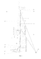
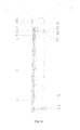
- the new system known as a repair/cleaning scaffolding tower for wind turbines, is able to carry out these maintenance and repair works on the blades, provided that the same is located near to the tower of the wind turbine, as described below.
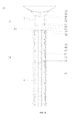
- the base (24) ( Figs. 2 , 3 and 4 ) of the scaffolding tower (1) ( Fig. 1 ) is located on a special lorry (20) ( Figs. 2 and 3 ), this lorry (20) ( Figs. 2 and 3 ) having the following characteristics:
- a hydraulic levelling system (21) ( Figs. 2 and 3 ), which consists of a number of extendable arms which come out of the structure of the lorry (20) itself ( Figs. 2 and 3 ), which should be supported on solid ground, in order to achieve complete stability in the lorry (20) ( Figs. 2 and 3 ), carrying the first stretch (25) ( Fig. 3 ) of the scaffolding tower (1) ( Fig. 1 ).
- this lorry (20) ( Figs. 2 and 3 ) is equipped with a 7500 litre water deposit (34) ( Figs. 2 and 3 ), a pressure lofter (35) ( Figs. 2 and 3 ) and a power generator (36) ( Figs. 2 and 3 ) for powering the electric system needed to carry out cleaning works on the blades (54) ( Figs.9 , 10 and 11 ).
- a television circuit and a scanner system (37) Figs. 2 and 3 ) for visualising the blades (54) ( Fig.
- the base (24) ( Figs. 2 , 3 and 4 ) of the scaffolding tower (1) ( Fig. 1 ) is mounted via a shaft onto a fork (22) ( Figs 2 and 3 ), which is fixed and joined to the chassis of the lorry (20) ( Figs. 2 and 3 ).
- This fork (22) ( Figs. 2 and 3 ), upon which the base (24) ( Figs. 2 , 3 and 4 ) of the scaffolding tower (1) ( Fig. 1 ) rotates, is lifted by means of a rotating pulley system (23) ( Figs. 2 and 3 ), which are motorised and leant back onto the chassis of the lorry (20) ( Figs. 2 and 3 ) and onto the base (24) ( Figs. 2 , 3 and 4 ) of the scaffolding tower (1) ( Fig.1 ) until they are aligned vertically.
- the base (24) ( Figs. 2 , 3 and 4 ) of the scaffolding tower (1) ( Fig. 1 ) has a dampening system (38) ( Figs. 2 and 3 ) in order to make the rotating pulley system (23) ( Figs. 2 and 3 ) brake, so that it is blocked when it has reached its working position.
- the base (24) ( Figs. 2 , 3 and 4 ) of the scaffolding tower (1) ( Fig. 1 ) will reach its working position when it comes into contact with the mast of the turbine (31) ( Figs. 1 , 2 , 3 and 5 ).
- This contact is achieved by means of a number of rubberized wheels (29) ( Figs. 1 and 5 ), which are located in the upper portion of the first stretch (25) ( Fig. 3 ) of the scaffolding tower (1) ( Fig. 1 ), these wheels being placed with a certain degree of rotation in order to embrace the mast of the turbine (31) ( Fig. 1 ).
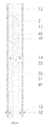
- the base (24) ( Figs. 1 , 2 , 3 , 4 and 5 ) of the scaffolding tower (1) ( Fig.1 ) is formed by a stretch of metal structure 10 meters high, the 2 final meters of the base (24) ( Figs. 2 , 3 and 4 ) of the scaffolding tower (1) ( Fig. 1 ) being closed (39) ( Fig.4 ) on all of its sides or wings. However, the 8 remaining meters are open (40) ( Fig. 4 ) at one of its wings (the various stretches (19) ( Fig.5 ) that form the scaffolding tower (1) ( Fig.1 ) being introduced through this opening).
- a fixed platform (27) ( Figs. 2 and 3 ) will be fitted, which is accessed by means of a safety ladder (28) ( Figs. 2 , 3 and 4 ) installed in the wing of the base (24) ( Figs. 2 , 3 and 4 ) of the scaffolding tower (1) ( Fig.1 ), this fixed platform (27) ( Figs. 2 and 3 ) serving to facilitate the assembly and mounting of all the components of the scaffolding tower (1) ( Fig.1 ).
- the inner corners of the base (24) ( Figs. 2 , 3 and 4 ) of the scaffolding tower (1) ( Fig. 1 ) are cylindrical (18) ( Fig. 4 ) in structure, so that the 12 convex guide wheels (17) ( Fig.4 ) coupled to the corners of the base (24) ( Figs. 2 , 3 and 4 ) of the scaffolding tower (1) ( Fig. 1 ) are able to rotate on them, these wheels being fastened by means of a rectangular structure (41) ( Fig.4 ), with three in each corner. These wheels will serve to help the gear motors (26) ( Fig.4 ) to move the internal mounting stretches (19) ( Fig.5 ).
- the metal stretches (19) ( Fig.5 ) of the scaffolding tower (1) are introduced through the base (24) ( Figs.2 , 3 ,and 4 ) of the scaffolding tower (1) ( Fig.1 ) in order to be subsequently hoisted by means of four gear motors (26) ( Fig.4 ), which are located in the upper portion of the base (24) ( Figs. 2 , 3 and 4 ) of the scaffolding tower (1) ( Fig. 1 ), housed precisely within the two wings adjacent to the open area of the base (24) ( Figs. 2 , 3 and 4 ) of the scaffolding tower (1) ( Fig. 1 ).
- the stretches (19) ( Fig. 5 ), which are introduced in the base (24) ( Figs. 2 , 3 and 4 ) of the scaffolding tower (1) ( Fig. 1 ), just like the base (24) ( Figs. 2 , 3 and 4 ) of the scaffolding tower (1) ( Fig. 1 ), are formed by a metal quadrangular structure, which measures 7.5 meters in height and is closed (42) ( Fig.5 ) at three of its sides, being part of an open wing (43) ( Fig. 5 ). At the ends of these wings are cylindrical tubes (44) ( Fig.5 ), which facilitate passage and help us to make the structure of the scaffolding tower (1) ( Fig. 1 ) rigid, at the working stage of the displacement system (12) ( Fig. 6 ) of the robotic arm (13) ( Figs. 7 and 8 ).
- the inner (45) ( Fig.5 ) and outer (46) ( Fig. 5 ) corners of these stretches are cylindrical in structure.
- the external (46) ( Fig. 5 ) cylindrical corners serve to facilitate the rotation of the 12 convex wheels (17) ( Fig. 4 ) on them, which are coupled to the corners of the base (24) ( Figs. 2 , 3 and 4 ) of the scaffolding tower (1) ( Fig. 1 ), which are coupled to a rectangular structure.
- the stretches (19) ( Fig. 5 ) introduced have a double zip (16) ( Fig.5 ) inserted into the left and right wings, which is what shall be used to elevate them.
- these stretches (19) ( Fig. 5 ) have an internal zip (16) ( Fig. 5 ) in their left and right wings, which serves to facilitate the internal movement of the displacement structure (12) ( Fig. 6 ) of the robotic arm (13) ( Figs. 7 and 8 ).
- the structural displacement stretch (12) ( Fig. 6 ) of the robotic arm (13) ( Figs. 7 and 8 ) is composed of a quadrangular metal structure, which is 6 meters in height, the first 2 meters and the final meter of the stretch of the structural displacement element (12) ( Fig. 6 ) being closed (48) ( Fig. 6 ) on all sides. However, the 3 remaining meters are open (49) ( Fig. 6 ) at one of their ends, the robotic arm (13) ( Figs. 7 and 8 ) which supports the basket (11) ( Figs. 9 , 10 and 11 ) therefore being able to move.
- the corners of the structural displacement stretch (12) ( Fig. 6 ) of the robotic arm (13) ( Figs. 7 and 8 ) are cylindrical in form (50) ( Fig. 8 ) and serve to enable the 12 convex wheels (47) ( Fig. 5 ) to rotate on them, with the corners of all the stretches (19) ( Fig. 5 ) which form the scaffolding tower (1) ( Fig 1 ) being coupled to them, therefore facilitating the displacement of the stretch carrying the robotic arm (13) ( Figs. 7 and 8 ) inside the scaffolding tower (1) ( Fig. 1 ).
- the structural displacement stretch (12) ( Fig. 6 ) with the robotic arm (13) ( Figs. 7 and 8 ), upon being inside the first mounting stretch (25) ( Fig. 3 ) of the base (24) ( Figs. 2 , 3 and 4 ) of the scaffolding tower (1) ( Fig. 1 ) shall be raised to an equal height with stretches (19) ( Fig. 3 ) coupled by the lower portion of the base (24) ( Figs. 2 , 3 and 4 ) of the scaffolding tower (1) ( Fig. 1 ) until they reach the desired height ( Fig. 1 ).
- the structural displacement stretch (12) ( Fig. 6 ) with the robotic arm (13) ( Figs. 7 and 8 ) will be lowered down to the head of the base (24) ( Figs. 2 , 3 and 4 ) of the scaffolding tower (1) ( Fig. 1 ).
- vents (32) ( Fig. 1 ) The stretches (19) ( Fig. 5 ) of the scaffolding tower (1) ( Fig. 1 ) will have the vents (32) ( Fig. 1 ), rubberized wheels (29) ( Figs. 1 and 5 ) and electromagnets (30) ( Figs. 1 and 5 ) needed to provide stable and safe working conditions.
- These vents (32) ( Fig. 1 ) just like the rubberised wheels (29) ( Figs. 1 and 5 ) and electromagnets (30) ( Figs. 1 and 5 ) will be mounted in unison with the hoisting of the scaffolding tower (1) ( Fig. 1 ).
- the vents (32) ( Fig. 1 ) were previously fixed to a hydraulic turbine system with operating voltage, which is fixed to the ground by means of foundations, used to anchor the vents (33) ( Fig. 1 ), before lowering the robotic arm (13) ( Figs. 7 and 8 ).
- the structural displacement stretch (12) ( Fig. 6 ) is moved by means of two gear motors (15) ( Figs. 6 , 7 and 8 ), which are coupled to the structure of this stretch.
- the gear motors (15) ( Figs. 6 , 7 and 8 ) with a number of built in crowns (52) ( Figs. 6 , 7 and 8 ) will be responsible for moving the scaffolding tower (1) ( Fig. 1 ) using the zips (16) ( Fig. 5 ) in the stretches (19) ( Fig. 5 ).
- the structural displacement system (12) ( Fig. 6 ) of the robotic arm (13) ( Figs. 7 and 8 ) has a built in structure with rotating wheels (51) ( Fig. 8 ) which will be embraced and moved by the external cylindrical tubes (44) ( Fig. 5 ) of the open portion (43) ( Fig. 5 ) of the scaffolding tower (1) ( Fig. 1 ), thereby achieving rigid working conditions in both the tower and the robotic arm (13) ( Figs. 7 and 8 ).
- the robotic arm (13) Figs. 7 and 8
- the operational basket (11) Figs. 9 , 10 and 11
- the robotic arm (13) may carry out vertical displacement manoeuvres owing to its toothed crowns in the rotation system ( Figs. 6 , 7 and 8 ) inside the displacement structure (12) ( Fig. 6 ), which is joined to this arm (13), this crown of the rotating system (53) ( Figs. 7 , 8 and 9 ) carrying out its movements via two gear motors (14) ( Figs. 6 and 8 ) with a brake which transmit their energy by means of crowns.
- This robotic arm (13) ( Figs. 7 and 8 ) and the crown of the rotation system (53) ( Figs. 6 , 7 and 8 ) for movement have a built in automatic levelling cam system (2) ( Fig. 7 ) to ensure the basket (11) ( Fig. 9 ) is always horizontal, this basket being joined to this robotic arm (13) ( Figs. 7 and 8 ).
- the basket (11) ( Fig. 9 ) which is joined to the robotic arm (13) ( Figs. 7 and 8 ) is a metal structure composed of various stretches (3) ( Fig. 9 ) coupled to one another by means of conical bearings (4) ( Fig. 9 ) and crowns for rotation (55) ( Fig. 9 ). It may also adopt any shape or form required to carry out the works ( Figs. 9 , 10 and 11 ).
- variable form metal stretches (3) ( Figs. 9 , 10 and 11 ) have a gangway (5) ( Fig. 9 ) to step on and a safety rail (6) ( Fig. 9 ) and admit various supports for the installation of their various applications, for example:
- the basket (11) ( Figs. 9 , 10 and 11 ) also have a semi-automatic manual system with security sensors (10) ( Fig. 9 ) so as not to damage the blades (54) ( Figs. 9 , 10 and 11 ) of the turbine.
- security sensors 10 ( Fig. 9 ) so as not to damage the blades (54) ( Figs. 9 , 10 and 11 ) of the turbine.
- the safety of the workers is considered a priority, given that should any circumstance arise or there be any reason for them having to move the basket (11) ( Fig. 11 ) (from where they work) from the blades' (54) ( Fig. 11 ) path, they could do so quickly and in the most effective way according to the circumstances.
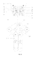
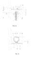
- One of the new accessories built into the scaffolding tower (60) is the ring clamp with a gangway (56) ( Figs. 12 , 13 and 14 ), which is built into the first stretch (61) ( Figs 12 and 13 ) of the scaffolding tower (60) ( Fig. 12 ). It is formed by two symmetrical variable form metal structures, which are coupled in parallel to the perimeter of the mast tower (62) ( Fig. 12 ) of the turbine. The same also have a number of joints and bracing (57) ( Figs. 12 , 13 and 14 ), thereby achieving the maximum stability and security thereof.
- the structure of the ring clamp with a gangway (56) (Figs. 12 , 13 and 14 ) has a number of rubberised wheels (58) ( Figs. 12 , 13 and 14 ), fitted in the upper and lower portion of the same.
- the wheels have a pneumatic system controlled by a pressure regulator (59), ( Figs. 12 and 13 ) used to achieve balance and stability in the scaffolding tower (60) ( Fig. 12 ) as it moves the auto-mounting on the mast tower (62) ( Fig. 12 ) in order to reach their various working positions.
- the structure of the ring clamp with a gangway (56) ( Figs. 12 , 13 and 14 ) to be stepped on also has railings (63) ( Figs. 12 and 13 ), safety skirting's (64) ( Figs. 12 and 13 ) and the various supports for the installation of the various systems:
- Another new accessory for the scaffolding tower is the ring clamps without a gangway (68) ( Fig. 12 ), which are built into the upper portion of the base (69) ( Fig. 12 ) of the scaffolding tower (60) ( Fig. 12 ) and into a number of stretches (70) ( Fig. 12 ) of the same, are necessary.
- This accessory is formed by two symmetrical variable form metal structures, which are coupled parallel to the perimeter of the mast tower (62) ( Fig. 12 ) of the turbine.
- the ring clamp structure (68) ( Fig. 12 ) has a number of rubberised wheels (58) ( Fig. 12 ) fitted in the upper and lower portion of the same.
- the wheels have a pneumatic system (59) ( Fig. 12 ) controlled by a pressure regulator, in order to achieve balance and stability in the scaffolding tower (60) ( Fig. 12 ) in the movement of the auto mounting on the mast tower (62) ( Fig. 12 ).
- the robotic arm (71) ( Fig. 15 ) inside the structural displacement stretch (72) ( Fig. 15 ) is assembled by means of penetrating an "L-shaped" structural piece (73), fixed with a pin (74) ( Fig. 15 ).
- the robotic arm displacement system (72) ( Fig. 15 ) will be lowered down to the head of the base (69) ( Fig. 12 ) of the scaffolding tower (60) ( Fig. 12 ); the robotic arm (71) ( Fig. 15 ) will be fitted in horizontal position and part of the robotic arm (75) ( Fig. 15 ) is withdrawn where the basket was connected for works on the blades. Meanwhile, the crowns of the rotation system (76) ( Fig.
- a gangway (78) ( Fig. 15 ) is fitted for stepping on, formed by a light variable form metal structure, with railings (63) ( Fig. 13 ) and safety skirtings (64) ( Fig 13 ) and the various supports for installing the various cleaning systems (65) ( Fig. 14 ), scanning systems (66) ( Fig. 14 ) and photography systems (67) ( Fig. 14 ) as well as general repair systems.
- the gangway (78) (Figs. 13 and 14 ) has a complementary gangway (79) ( Figs. 13 and 14 ) which enables workers to walk from the same to the ring clamp with a gangway and vice versa.
- the gangway of the "L-shaped" robotic arm (73) ( Fig. 15 ) has a number of joints and bracing (81) ( Figs. 13 and 14 ), thereby achieving the maximum stability and safety thereof.
Landscapes
- Engineering & Computer Science (AREA)
- Architecture (AREA)
- Mechanical Engineering (AREA)
- Structural Engineering (AREA)
- Life Sciences & Earth Sciences (AREA)
- Civil Engineering (AREA)
- Sustainable Energy (AREA)
- General Engineering & Computer Science (AREA)
- Combustion & Propulsion (AREA)
- Chemical & Material Sciences (AREA)
- Sustainable Development (AREA)
- Geology (AREA)
- Movable Scaffolding (AREA)
- Wind Motors (AREA)
Applications Claiming Priority (1)
| Application Number | Priority Date | Filing Date | Title |
|---|---|---|---|
| PCT/ES2011/000134 WO2012140278A1 (es) | 2011-04-14 | 2011-04-14 | Torre andamio reparadora-limpiadora para aerogeneradores eólicos. |
Publications (2)
| Publication Number | Publication Date |
|---|---|
| EP2698528A1 true EP2698528A1 (de) | 2014-02-19 |
| EP2698528A4 EP2698528A4 (de) | 2014-10-01 |
Family
ID=47008856
Family Applications (1)
| Application Number | Title | Priority Date | Filing Date |
|---|---|---|---|
| EP11863488.0A Withdrawn EP2698528A4 (de) | 2011-04-14 | 2011-04-14 | Reparatur/reinigungsgerüstturm für windturbinen |
Country Status (4)
| Country | Link |
|---|---|
| US (1) | US20140034418A1 (de) |
| EP (1) | EP2698528A4 (de) |
| MX (1) | MX2013012043A (de) |
| WO (1) | WO2012140278A1 (de) |
Cited By (2)
| Publication number | Priority date | Publication date | Assignee | Title |
|---|---|---|---|---|
| CN104819108A (zh) * | 2015-05-15 | 2015-08-05 | 湖南大学 | 一种风力发电机塔筒外壁维护施工装置 |
| EP3499030A1 (de) * | 2017-12-14 | 2019-06-19 | The Boeing Company | Verfahren und vorrichtung zur wartung von windturbinenschaufeln |
Families Citing this family (9)
| Publication number | Priority date | Publication date | Assignee | Title |
|---|---|---|---|---|
| NZ589895A (en) * | 2008-06-26 | 2013-02-22 | Pp Energy Aps | Device for enabling access to a wind turbine rotor blade which can be lifted and giuded to the blade |
| US10650582B2 (en) * | 2015-04-14 | 2020-05-12 | ETAK Systems, LLC | Systems and methods for closing out maintenance or installation work at a telecommunications site |
| ES2603434B1 (es) * | 2015-08-17 | 2017-12-22 | Gamesa Innovation & Technology, S.L. | Máquina de limpieza exterior en torres de aerogeneradores |
| US10648235B2 (en) * | 2016-08-15 | 2020-05-12 | The Boeing Company | Work stand configurable for different work areas |
| DK3434639T3 (da) | 2017-07-27 | 2019-12-09 | S&L Access Systems Ab | Løftekonstruktion til løft af komponenter til en vindmølle og fremgangsmåde til anvendelse af løftekonstruktionen |
| WO2020065103A1 (es) * | 2018-09-28 | 2020-04-02 | Colino Llamas Carlos | Sistema y método para mantenimiento turbina eólica |
| CN114837399B (zh) * | 2022-05-06 | 2023-05-26 | 上海建工四建集团有限公司 | 一种适用于盘扣式钢管的铲刀梁 |
| CN115681030A (zh) * | 2022-11-28 | 2023-02-03 | 山东高熵金属科技有限公司 | 风力发电风车叶片维修厢式多功能维修安全仓 |
| CN117028178B (zh) * | 2023-09-08 | 2024-02-09 | 北京国领智能科技有限公司 | 一种曲面自适应气动多模块刮板清洁组件 |
Family Cites Families (46)
| Publication number | Priority date | Publication date | Assignee | Title |
|---|---|---|---|---|
| US3493079A (en) * | 1967-12-18 | 1970-02-03 | Dallas L Dudschus | Foldable,adjustable height platform assembly mountable on a vehicle |
| US3938670A (en) * | 1969-04-09 | 1976-02-17 | General Crane Industries Limited | Tower crane |
| GB1404136A (en) * | 1971-11-04 | 1975-08-28 | Gen Crane Industries | Mobile load holding means particularly tower cranes |
| US5159993A (en) * | 1991-10-15 | 1992-11-03 | Gestion Des Brevets Fraco Limitee | Self-raising work platform assembly |
| US5259479A (en) * | 1991-10-15 | 1993-11-09 | Gestion Des Brevets Fraco Ltee | Self-raising cantilever-type work platform assembly |
| DE4406987C1 (de) * | 1994-03-03 | 1995-07-06 | Paul Lingen | Hubgerüst |
| US5636705A (en) * | 1995-05-24 | 1997-06-10 | St-Germain; Andre | Apparatus for moving a work platform along a rail |
| FR2774083B1 (fr) * | 1998-01-27 | 2000-04-07 | Kidde Ind Inc | Dispositif elevateur perfectionne |
| DE10022600B4 (de) * | 1999-06-28 | 2007-09-27 | Terex-Demag Gmbh & Co. Kg | Teleskopkran |
| DE19938578A1 (de) * | 1999-08-18 | 2001-02-22 | Delmag Maschinenfabrik | Fahrbares Arbeitsgerät |
| JP4012974B2 (ja) * | 2000-03-09 | 2007-11-28 | 東京電力株式会社 | 風力発電タワーの組立装置及び組立方法 |
| US7521083B2 (en) * | 2001-12-06 | 2009-04-21 | Pp Energy Aps | Method and apparatus for treatment of a rotor blade on a windmill |
| US7207777B2 (en) * | 2002-05-27 | 2007-04-24 | Vesta Wind Systems A/S | Methods of handling wind turbine blades and mounting said blades on a wind turbine, system and gripping unit for handling a wind turbine blade |
| EP1534953A1 (de) * | 2002-09-04 | 2005-06-01 | PP Energy ApS | Verfahren und vorrichtung zum anheben und/oder absenken von objekten an einer windturbine oder dergleichen und verwendungen davon |
| US7395899B2 (en) * | 2003-01-27 | 2008-07-08 | Exterior Elevator, Llc | Method and apparatus for reaching from outside an upper level of a tall structure |
| DE10311674B4 (de) * | 2003-03-11 | 2007-02-01 | aeroconcept Ingenieurgesellschaft für Luftfahrttechnik und Faserverbundtechnologie mbH | Wartungsplattform |
| US7934585B2 (en) * | 2003-04-15 | 2011-05-03 | Vestas Wind Systems A/S | Method of servicing the outer components of a wind turbine such as the wind turbine blades and the tower with a work platform and work platform |
| WO2004111443A1 (en) * | 2003-06-11 | 2004-12-23 | General Electric Company | Remote shut down of offshore wind turbine |
| ES2244292A1 (es) * | 2003-09-19 | 2005-12-01 | Peri, S.A. | Dispositivo elevador de personas por el fuste de un aerogenerador. |
| WO2005054672A1 (en) * | 2003-12-04 | 2005-06-16 | Pp Energy Aps | Method and apparatus for treatment of a part of a wind turbine |
| AU2004308998B2 (en) * | 2003-12-30 | 2010-01-28 | Pp Energy Aps | Device for enabling access to a structure above ground level |
| SE526546C2 (sv) * | 2004-03-12 | 2005-10-04 | Alimak Ab | Hissystem |
| GB2417499B (en) * | 2004-08-24 | 2010-02-17 | Marks Barfield Ltd | Observation tower |
| ES2354178T3 (es) * | 2004-12-03 | 2011-03-10 | Manitowoc Crane Group Germany Gmbh | Grúa automotriz. |
| US8201787B2 (en) * | 2005-01-19 | 2012-06-19 | Iti Scotland Limited | Clamp, self-advancing climbing device, and method of coupling same to a tubular |
| US7278198B2 (en) * | 2005-02-01 | 2007-10-09 | The Boeing Company | Mandrel segment loader |
| NZ570732A (en) * | 2006-01-27 | 2010-09-30 | Pp Energy Aps | Device that surrounds a rotor blade on a wind turbine, running on the inner and outer edges of the blade |
| DE102007003000B4 (de) * | 2006-09-04 | 2008-07-24 | Jeremy Sheppard | Vorrichtung zum Befahren einer Windenergieanlage |
| US8381460B1 (en) * | 2007-02-27 | 2013-02-26 | Patrick P. McDermott | Extendable beam structure (EBS) |
| US20080302605A1 (en) * | 2007-06-08 | 2008-12-11 | Andre St-Germain | Size adjustable platform for scaffolding |
| NZ589895A (en) * | 2008-06-26 | 2013-02-22 | Pp Energy Aps | Device for enabling access to a wind turbine rotor blade which can be lifted and giuded to the blade |
| AT506625B1 (de) * | 2008-09-04 | 2009-10-15 | Palfinger Systems Gmbh | Instandhaltungsplattform |
| DE112010002148A5 (de) * | 2009-05-29 | 2012-10-31 | Ebf Dresden Gmbh | Vorrichtung für inspektions- und wartungsarbeiten an rotorblättern und/ oder der turmoberfläche grosser windkraftanlagen, insbesondere off-shore-anlagen |
| US8062431B2 (en) * | 2009-06-16 | 2011-11-22 | General Electric Company | Method and apparatus for cleaning and de-icing wind turbine rotor blades |
| GB201002581D0 (en) * | 2010-02-16 | 2010-03-31 | Extreme Access Hire Ltd | Service platform |
| CA2699556C (en) * | 2010-04-15 | 2012-03-13 | Energera Inc. | Mobile elevating work platform |
| US8621954B1 (en) * | 2010-06-04 | 2014-01-07 | University Of Washington Through Its Center For Commercialization | Systems and methods for gravity compensation |
| NL2004871C2 (nl) * | 2010-06-10 | 2011-12-13 | Special Blade Service B V | Hoogwerker voor windturbines. |
| WO2011163498A2 (en) * | 2010-06-23 | 2011-12-29 | Jensen dustin | Wind turbine blade treatment apparatuses and methods |
| US8965571B2 (en) * | 2010-08-12 | 2015-02-24 | Construction Robotics, Llc | Brick laying system |
| CN102434403B (zh) * | 2010-09-29 | 2015-09-09 | 通用电气公司 | 用于风力涡轮机检查的系统及方法 |
| US8743196B2 (en) * | 2010-12-16 | 2014-06-03 | General Electric Company | System and method for performing an external inspection on a wind turbine rotor blade |
| US8579085B2 (en) * | 2010-12-29 | 2013-11-12 | Sky Climber Llc | Suspended access chair with rescue system |
| US8347900B2 (en) * | 2011-04-05 | 2013-01-08 | Jensen dustin | Wind turbine fluid application apparatus |
| US20130228397A1 (en) * | 2012-03-02 | 2013-09-05 | Tom D. Horn | Wind tower maintenance platforms and techniques |
| US9550661B2 (en) * | 2012-11-23 | 2017-01-24 | Fiducie Familiale Andre St-Germain | Self-contained, portable and self-supporting scaffolding kit |
-
2011
- 2011-04-14 WO PCT/ES2011/000134 patent/WO2012140278A1/es not_active Ceased
- 2011-04-14 MX MX2013012043A patent/MX2013012043A/es not_active Application Discontinuation
- 2011-04-14 US US14/111,920 patent/US20140034418A1/en not_active Abandoned
- 2011-04-14 EP EP11863488.0A patent/EP2698528A4/de not_active Withdrawn
Cited By (3)
| Publication number | Priority date | Publication date | Assignee | Title |
|---|---|---|---|---|
| CN104819108A (zh) * | 2015-05-15 | 2015-08-05 | 湖南大学 | 一种风力发电机塔筒外壁维护施工装置 |
| EP3499030A1 (de) * | 2017-12-14 | 2019-06-19 | The Boeing Company | Verfahren und vorrichtung zur wartung von windturbinenschaufeln |
| US10634123B2 (en) | 2017-12-14 | 2020-04-28 | The Boeing Company | Apparatus and methods for maintenance of wind turbine blades |
Also Published As
| Publication number | Publication date |
|---|---|
| MX2013012043A (es) | 2014-05-27 |
| US20140034418A1 (en) | 2014-02-06 |
| EP2698528A4 (de) | 2014-10-01 |
| WO2012140278A1 (es) | 2012-10-18 |
Similar Documents
| Publication | Publication Date | Title |
|---|---|---|
| EP2698528A1 (de) | Reparatur/reinigungsgerüstturm für windturbinen | |
| CN101798993B (zh) | 用于风力涡轮机塔架的内部偏航驱动器置换 | |
| EP2433001B1 (de) | Nabe für eine windturbine | |
| US9446446B2 (en) | System and method for assembling and disassembling components from a wind power turbine | |
| DK2715113T3 (en) | METHOD FOR SETTING UP, MAINTAINING AND DISASSEMBLING A WIND TURBINE | |
| EP3001029B1 (de) | Gegengewichtssysteme für eine Windturbine und Verfahren | |
| DK2507514T3 (en) | Wind energy system with hoisting device | |
| DK2924284T3 (en) | Counterbalance of a wind turbine hub | |
| US9469512B2 (en) | Lifting device for assembly and disassembly of wind turbine components | |
| EP3091222A1 (de) | System und verfahren zum ersetzen eines blattlagers | |
| CN105270986A (zh) | 风力涡轮机叶片起吊设备及用于起吊风力涡轮机叶片的方法 | |
| US10781794B2 (en) | Installing blades in a wind turbine and wind turbine lifting systems | |
| KR101021447B1 (ko) | 풍력 발전 장치의 로터 헤드 내 기기 승강 방법 | |
| WO2013102460A1 (en) | Suspension system for wind turbines | |
| US10641042B2 (en) | External ladder assembly for wind turbine nacelle | |
| EP3475557B1 (de) | Eine windturbine mit parkierender struktur, um den rotor während ersätzen der gondel zu tragen | |
| CN117231445A (zh) | 一种自动爬升式风力发电机环形检修平台 | |
| CN109072866B (zh) | 提升多转子风轮机的部件的方法 | |
| CN221027523U (zh) | 一种对风力发电机全方位维修的机器平台 | |
| EP3382200A1 (de) | Nabenkrananordnung für eine windturbine | |
| EP2532879B1 (de) | Montage und/oder Instandhaltung einer Windturbine | |
| EP4077932B1 (de) | Verfahren zum installieren oder entfernen von windturbinenkomponenten | |
| JP7213515B2 (ja) | 塔上可動足場用構造、塔上可動足場および塔上作業方法 | |
| CN201647896U (zh) | 兆瓦级风力发电机内变浆电机吊装装置 | |
| CN117228596A (zh) | 一种对风力发电机全方位维修的机器平台 |
Legal Events
| Date | Code | Title | Description |
|---|---|---|---|
| PUAI | Public reference made under article 153(3) epc to a published international application that has entered the european phase |
Free format text: ORIGINAL CODE: 0009012 |
|
| 17P | Request for examination filed |
Effective date: 20131114 |
|
| AK | Designated contracting states |
Kind code of ref document: A1 Designated state(s): AL AT BE BG CH CY CZ DE DK EE ES FI FR GB GR HR HU IE IS IT LI LT LU LV MC MK MT NL NO PL PT RO RS SE SI SK SM TR |
|
| DAX | Request for extension of the european patent (deleted) | ||
| A4 | Supplementary search report drawn up and despatched |
Effective date: 20140902 |
|
| RIC1 | Information provided on ipc code assigned before grant |
Ipc: E04G 1/36 20060101ALI20140827BHEP Ipc: E04G 5/00 20060101ALI20140827BHEP Ipc: E04G 1/38 20060101ALI20140827BHEP Ipc: F03D 1/00 20060101AFI20140827BHEP Ipc: F03D 11/00 20060101ALI20140827BHEP Ipc: B66F 11/04 20060101ALI20140827BHEP |
|
| STAA | Information on the status of an ep patent application or granted ep patent |
Free format text: STATUS: REQUEST FOR EXAMINATION WAS MADE |
|
| STAA | Information on the status of an ep patent application or granted ep patent |
Free format text: STATUS: THE APPLICATION IS DEEMED TO BE WITHDRAWN |
|
| 18D | Application deemed to be withdrawn |
Effective date: 20171103 |