EP3783253B1 - Überwachungssystem - Google Patents
Überwachungssystem Download PDFInfo
- Publication number
- EP3783253B1 EP3783253B1 EP19789475.1A EP19789475A EP3783253B1 EP 3783253 B1 EP3783253 B1 EP 3783253B1 EP 19789475 A EP19789475 A EP 19789475A EP 3783253 B1 EP3783253 B1 EP 3783253B1
- Authority
- EP
- European Patent Office
- Prior art keywords
- temperature
- abnormality
- steam trap
- water
- discharge
- Prior art date
- Legal status (The legal status is an assumption and is not a legal conclusion. Google has not performed a legal analysis and makes no representation as to the accuracy of the status listed.)
- Active
Links
Images


Classifications
-
- F—MECHANICAL ENGINEERING; LIGHTING; HEATING; WEAPONS; BLASTING
- F16—ENGINEERING ELEMENTS AND UNITS; GENERAL MEASURES FOR PRODUCING AND MAINTAINING EFFECTIVE FUNCTIONING OF MACHINES OR INSTALLATIONS; THERMAL INSULATION IN GENERAL
- F16T—STEAM TRAPS OR LIKE APPARATUS FOR DRAINING-OFF LIQUIDS FROM ENCLOSURES PREDOMINANTLY CONTAINING GASES OR VAPOURS
- F16T1/00—Steam traps or like apparatus for draining-off liquids from enclosures predominantly containing gases or vapours, e.g. gas lines, steam lines, containers
- F16T1/38—Component parts; Accessories
- F16T1/48—Monitoring arrangements for inspecting, e.g. flow of steam and steam condensate
-
- G—PHYSICS
- G01—MEASURING; TESTING
- G01J—MEASUREMENT OF INTENSITY, VELOCITY, SPECTRAL CONTENT, POLARISATION, PHASE OR PULSE CHARACTERISTICS OF INFRARED, VISIBLE OR ULTRAVIOLET LIGHT; COLORIMETRY; RADIATION PYROMETRY
- G01J5/00—Radiation pyrometry, e.g. infrared or optical thermometry
- G01J5/0003—Radiation pyrometry, e.g. infrared or optical thermometry for sensing the radiant heat transfer of samples, e.g. emittance meter
-
- G—PHYSICS
- G01—MEASURING; TESTING
- G01J—MEASUREMENT OF INTENSITY, VELOCITY, SPECTRAL CONTENT, POLARISATION, PHASE OR PULSE CHARACTERISTICS OF INFRARED, VISIBLE OR ULTRAVIOLET LIGHT; COLORIMETRY; RADIATION PYROMETRY
- G01J5/00—Radiation pyrometry, e.g. infrared or optical thermometry
- G01J5/10—Radiation pyrometry, e.g. infrared or optical thermometry using electric radiation detectors
- G01J5/28—Radiation pyrometry, e.g. infrared or optical thermometry using electric radiation detectors using photoemissive or photovoltaic cells
-
- G—PHYSICS
- G01—MEASURING; TESTING
- G01K—MEASURING TEMPERATURE; MEASURING QUANTITY OF HEAT; THERMALLY-SENSITIVE ELEMENTS NOT OTHERWISE PROVIDED FOR
- G01K11/00—Measuring temperature based upon physical or chemical changes not covered by groups G01K3/00, G01K5/00, G01K7/00 or G01K9/00
- G01K11/12—Measuring temperature based upon physical or chemical changes not covered by groups G01K3/00, G01K5/00, G01K7/00 or G01K9/00 using changes in colour, translucency or reflectance
-
- F—MECHANICAL ENGINEERING; LIGHTING; HEATING; WEAPONS; BLASTING
- F16—ENGINEERING ELEMENTS AND UNITS; GENERAL MEASURES FOR PRODUCING AND MAINTAINING EFFECTIVE FUNCTIONING OF MACHINES OR INSTALLATIONS; THERMAL INSULATION IN GENERAL
- F16T—STEAM TRAPS OR LIKE APPARATUS FOR DRAINING-OFF LIQUIDS FROM ENCLOSURES PREDOMINANTLY CONTAINING GASES OR VAPOURS
- F16T1/00—Steam traps or like apparatus for draining-off liquids from enclosures predominantly containing gases or vapours, e.g. gas lines, steam lines, containers
- F16T1/20—Steam traps or like apparatus for draining-off liquids from enclosures predominantly containing gases or vapours, e.g. gas lines, steam lines, containers with valves controlled by floats
- F16T1/22—Steam traps or like apparatus for draining-off liquids from enclosures predominantly containing gases or vapours, e.g. gas lines, steam lines, containers with valves controlled by floats of closed-hollow-body type
- F16T1/24—Steam traps or like apparatus for draining-off liquids from enclosures predominantly containing gases or vapours, e.g. gas lines, steam lines, containers with valves controlled by floats of closed-hollow-body type using levers
-
- F—MECHANICAL ENGINEERING; LIGHTING; HEATING; WEAPONS; BLASTING
- F16—ENGINEERING ELEMENTS AND UNITS; GENERAL MEASURES FOR PRODUCING AND MAINTAINING EFFECTIVE FUNCTIONING OF MACHINES OR INSTALLATIONS; THERMAL INSULATION IN GENERAL
- F16T—STEAM TRAPS OR LIKE APPARATUS FOR DRAINING-OFF LIQUIDS FROM ENCLOSURES PREDOMINANTLY CONTAINING GASES OR VAPOURS
- F16T1/00—Steam traps or like apparatus for draining-off liquids from enclosures predominantly containing gases or vapours, e.g. gas lines, steam lines, containers
- F16T1/34—Steam traps or like apparatus for draining-off liquids from enclosures predominantly containing gases or vapours, e.g. gas lines, steam lines, containers without moving parts other than hand valves, e.g. labyrinth type
Definitions
- the present invention relates to a monitoring system.
- a steam trap is provided in the steam line.
- the steam trap serves to discharge the liquid drain water selectively from the water vapor flowing in piping to the outside of the line.
- Patent Documents 1 to 3 Having a worker inspect whether an abnormality is present in the steam trap provided in the steam line on a daily basis is a conceivable way to avoid such a trouble.
- large-scale factories such as steel-making factories and paper-making factories are provided with a large number of steam traps. Inspecting each of the steam traps scattered in such a factory is a burden on the worker.
- Patent Document 4 a technique in which the temperature of a steam trap is observed by using a temperature label.
- Patent Document 4 a technique in which the temperature of a steam trap is observed by using a temperature label.
- this case also requires a worker to perform inspections by walking around the factory, and thus cannot reduce the burden on the worker.
- Patent Document 5 discloses a diagnostic device 40 for a drain trap 1 comprising a temperature/pressure sensor 41 for detecting a temperature (i.e., a fluid temperature T2) and a pressure (i.e., a fluid pressure P2) of fluid flowing through a discharge passage 15 of the drain trap 1, a heat conductive member 43 having one surface coming in contact with the fluid and the other surface facing the outside of the drain trap 1, a temperature sensor 42 for detecting a temperature (i.e., a member temperature T3) of the other surface of the heat conductive member 43, and a diagnostic section 45.
- the drain trap 1 includes a float 16 and a valve seat member 20 with a valve port 22.
- the diagnostic section 45 determines that an abnormality is present when the fluid temperature T2 detected by the temperature/pressure sensor 41 is lower than a corresponding saturation temperature of the fluid pressure P2, or when the fluid temperature T2 is equal to the corresponding saturation temperature of the fluid pressure P2 and the member temperature T3 detected by the temperature sensor 42 exceeds a prescribed determination threshold Ts.
- An object of the present disclosure is to provide a monitoring system that facilitates inspection of a steam trap.
- the monitoring system according to the invention is described in claim 1.
- One aspect provides a monitoring system comprising: a steam trap including a supply portion into which water vapor is supplied, and a discharge portion which discharges liquid water contained in the water vapor; a temperature measurer that measures a temperature of at least the discharge portion; a transmitter that transmits temperature information containing the temperature measured by the temperature measurer; a receiver that receives the temperature information; a determiner that determines whether an abnormality is present in the steam trap based on the temperature information; and a notifier that issues a notice when the determiner determines that the abnormality is present.
- the transmitter transmits temperature information to the receiver, and the determiner determines whether an abnormality is present in the steam trap based on this temperature information. In this way, a worker does not need to inspect the steam trap himself or herself in the field. This can reduce the burden on the worker and facilitate inspection of the steam trap.
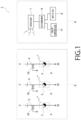
- FIG. 1 is a system configuration diagram of a monitoring system according to this embodiment.
- This monitoring system 1 is a system that monitors steam traps 3 provided in a factory 2, and has a monitoring unit 4 that monitors the steam traps 3 for abnormalities.
- a plurality of pipes 5 are installed in the factory 2 and each of them is provided with a steam trap 3 and a release valve 16. While the function of the pipes 5 is not particularly limited, steam pipes through which water vapor V used in, for example, a heat exchanger, flows can be used as the pipes 5. Also, examples of the factory 2 include a paper-making factory, a steel-making factory, a semiconductor factory, and so on.
- Each steam trap 3 separates liquid water from the water vapor V flowing through the pipe 5, and discharges this water as drain water W.
- the release valve 16 is a solenoid valve that, if drain water W accumulates in the pipe 5 due to the occurrence of an abnormality in the steam trap 3, releases this drain water W to the outside of the pipe 5.
- the steam trap 3 is provided with a transmission unit 6 that wirelessly transmits temperature information containing the temperature of the steam trap 3 to the monitoring unit 4.
- the standard for the wireless transmission is not particularly limited.
- the transmission unit 6 may perform the wireless transmission in accordance with a near-field communication standard such as ZIGBEE (registered trademark), Bluetooth (registered trademark), or iBeacon (registered trademark).
- a wireless LAN Local Area Network
- the monitoring unit 4 includes a receiver 7, a determiner 8, a notifier 9, and a valve controller 17.
- the receiver 7 receives the temperature information wirelessly transmitted from the transmission unit 6 with a reception antenna, and notifies the determiner 8 of the temperature information.
- the determiner 8 determines whether an abnormality is present in the steam trap 3, and notifies the notifier 9 of the result of this determination.
- the hardware configuration of the determiner 8 is not particularly limited.
- the determiner 8 can be implemented with a processor such as a CPU (Central Processor Unit) and a memory cooperating with each other to execute a program.
- a processor such as a CPU (Central Processor Unit) and a memory cooperating with each other to execute a program.
- the notifier 9 issues a notice with a screen or sound indicating the presence of the abnormality in the steam trap 3.
- a liquid crystal display or a speaker can be used as the notifier 9.
- a mobile terminal such as a smartphone or a PHS (Personal Handy-Phone System) may be used as the notifier 9.
- the determiner 8 wirelessly transmits the determination result indicating the presence of the abnormality to such a mobile terminal.
- the determiner 8 may notify the notifier 9 of an identifier identifying a steam trap 3 with an abnormality, and the notifier 9 may issue a notice indicating only the steam trap 3 with the abnormality among the plurality of steam traps 3.
- an identifier is, for example, an identification number assigned to each steam trap 3 by the administrator of the monitoring system 1.
- the valve control part 17 controls the release valve 16 to open the release valve 16 and release liquid water W to the outside of the pipe 5.
- FIG. 2 is a top view of a steam trap 3.
- the steam trap 3 is a nozzle steam trap made of a corrosion-resistant metal, such as stainless steel, and has a supply portion 10 which is connected to the pipe 5 (see FIG. 1 ) and into which water vapor V is supplied, and a discharge portion 11 which discharges the liquid water W contained in the water vapor V
- the supply portion 10 is provided therein with a supply channel 3a through which the water vapor V flows, and the discharge portion 11 is provided therein with a discharge channel 3b through which the water W flows.
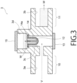
- FIG. 3 is a cross-sectional view of the steam trap 3 taken along the line I-I of FIG. 2 .
- a cavity 3c communicating with the above-mentioned supply channel 3a.
- the cavity 3c has a cylindrical shape extending vertically upward, with its lower end closed with a first end cap 13.
- a strainer 12 for filtering out foreign matters such as rust contained in the vapor V is provided in a detachably attachable manner.
- the shape and material of the strainer 12 are not particularly limited.
- a metal mesh through which a plurality of holes with a diameter of about 0.1 mm are formed is employed as the strainer 12.
- the liquid water W having passed through the strainer 12 is guided to a nozzle 14 fixed at the upper end of the cavity 3c.
- the nozzle 14 has a function of removing the liquid water W from the vapor V by generating a pressure difference between a water storage portion 3d provided in the steam trap 3 and the cavity 3c, and has a nozzle hole 14a from which the water W and part of the vapor V are jetted.
- the water storage portion 3d serves to temporarily store the water W exiting the nozzle 14.
- the steam trap 3 is used in such an orientation that the water storage portion 3d is positioned above the cavity 3c.
- FIG. 4 is a cross-sectional view of the steam trap 3 taken along the line II-II of FIG. 2 .
- the water W is stored to an intermediate depth. Moreover, an opening 3e is provided at a position lower than a water surface S of the water W.
- the opening 3e is connected to the discharge channel 3b by a connection channel 3g, so that the water W stored in the water storage portion 3d is discharged from the discharge portion 11 through the connection channel 3g.
- Such a steam trap 3 has no movable portion and thus has good durability, which enables a long-term use of the steam trap 3 in a steel-making factory or a paper-making factory.
- the opening 3e is provided in the water storage portion 3d at a position lower than the water surface S, the water W seals the opening 3e. This can prevent the water vapor V from escaping to the discharge portion 11 through the opening 3e.
- FIG. 5 is a configuration diagram of the transmission unit 6.
- the transmission unit 6 is a unit that wirelessly transmits the temperature information containing the temperature of the steam trap 3, as described earlier, and has a temperature measurer 20 and a transmitter 24.
- the temperature measurer 20 comprises a first temperature indicator 21, a second temperature indicator 22, and a camera 23.
- the first temperature indicator 21 is a piece of temperature indicating tape attached to the supply portion 10 of the steam trap 3, and changes its color at a first reference temperature T 1 set in advance for the supply portion 10.
- the second temperature indicator 22 is a piece of temperature indicating tape attached to the discharge portion 11 of the steam trap 3, and changes its color at a second reference temperature T 2 set in advance for the discharge portion 11.
- temperature indicators 21 and 22 are not limited to temperature indicating tapes. Paints that change their colors according to temperature or components coated with these paints may be used as the temperature indicators 21 and 22.
- the camera 23 observes the colors of the first temperature indicator 21 and the second temperature indicator 22 and notifies the transmitter 24 of information on those colors. Meanwhile, if the steam trap 3 is provided in a dark area, lighting that illuminates the temperature indicators 21 and 22 may be provided to make it easier to observe the colors of the temperature indicators 21 and 22 with the camera 23.
- temperature indicators 21 and 22 are simultaneously observed with a single camera 23 in this example, a dedicated camera may be provided for each of the first temperature indicator 21 and the second temperature indicator 22.
- the transmitter 24 wirelessly transmits the information on the colors as temperature information to the receiver 7 (see FIG. 1 ) with a transmission antenna.
- the colors of the first temperature indicator 21 and the second temperature indicator 22 serve as indicators with which to determine whether an abnormality is present in the steam trap 3 as described below.
- FIG. 6 is a partially cross-sectional side view of the steam trap 3 in an ideal state without an abnormality.
- the supply portion 10 When there is no abnormality, the supply portion 10 is heated by the water vapor V while being slightly cooled by the ambient air. Thus, the temperature of the supply portion 10 is only slightly below the temperature of the water vapor V
- the temperature of the discharge portion 11 is lower than a boiling point T v of water under the pressure on the water W.
- T v of water refers to a boiling point with pressure taken into account as above.
- FIG. 7 is a partially cross-sectional side view of the steam trap 3 with an abnormality occurring therein.
- liquid water W stagnates in the supply portion 10, so that the temperature of the supply portion 10 (145°C) is well below the temperature of the vapor V (170°C).
- the first reference temperature T 1 at which the first temperature indicator 21 changes its color, may just need to be about 155°C, which is only certain degrees lower than the temperature of the vapor V to be supplied to the supply portion 10 (170°C). Note that this temperature can be selected as appropriate according to the material of the pipe 5 and whether a heat insulating material is wound around the pipe 5. This also applies to temperatures to be described later including the first and second reference temperatures T 1 and T 2 .
- the first temperature indicator 21 changes its color. This enables the determiner 8 to determine which temperature is higher, the temperature of the supply portion 10 or the first reference temperature T 1 , based on the information on the color of the first temperature indicator 21. If the temperature of the supply portion 10 is lower than the first reference temperature T 1 , the determiner 8 determines that an abnormality is present in the steam trap 3. Upon receipt of this determination result, the notifier 9 notifies the administrator of the presence of the abnormality with a sound or a screen.
- the administrator Upon receipt of the notice, the administrator replaces the nozzle 14 with one having a nozzle hole 14a (see FIG. 3 ) with a larger diameter than the current one. This can solve the stagnation of the water W in the supply portion 10 and thus solve the abnormality.
- valve controller 17 having received the result of the determination by the determiner 8 may open the release valve 16 and release the water W from the release valve 16. In this way, the water W can be quickly discharged from the steam line before a worker replaces the nozzle 14. This can prevent the water W from causing the steam hammer phenomenon.
- the first reference temperature T 1 is, as described above, a temperature serving as a target point for determining that liquid water W stagnates in the supply portion 10. If this temperature is excessively low, there is a fear that the first temperature indicator 21 does not change its color although the water W stagnates in the supply portion 10, which leads to a failure to detect the abnormality. It is therefore preferable to keep the difference between the temperature of the vapor V and the first reference temperature T 1 within 10°C.
- FIG. 8 is a partially cross-sectional side view of the steam trap 3 with a different abnormality from that in FIG. 7 occurring therein.
- the second reference temperature T 2 at which the second temperature indicator 22 changes its color, may just need to be a predetermined temperature higher than the boiling point T v .
- the second reference temperature T 2 be 105°C, which is about 5°C higher than the boiling point T v (100°C), in a case where the discharge portion 11 is open to the atmosphere and the pressure inside the discharge portion 11 is the atmospheric pressure.
- the second temperature indicator 22 changes its color. This enables the determiner 8 to determine which temperature is higher, the temperature of the discharge portion 11 or the second reference temperature T 2 , based on the information on the color of the second temperature indicator 22. If the temperature of the discharge portion 11 is higher than the second reference temperature T 2 , the determiner 8 determines that an abnormality is present in the steam trap 3. Upon receipt of this determination result, the notifier 9 notifies the administrator of the presence of the abnormality with a sound or a screen.
- the administrator Upon receipt of the notice, the administrator replaces the nozzle 14 with one having a nozzle hole 14a (see FIG. 3 ) with a smaller diameter than the current one. This can stop the leakage of the vapor V to the discharge portion 11 and thus solve the abnormality.
- the second reference temperature T 2 is, as described above, a temperature serving as a target point for determining whether the vapor V is leaking to the discharge portion 11. If this temperature is excessively high, there is a fear that the second temperature indicator 22 does not change its color although the vapor V is leaking to the discharge portion 11, which will lead to a failure to detect the abnormality. It is therefore preferable to keep the difference between the second reference temperature T 2 and the boiling point T v of water within 10°C.
- FIG. 9 is a diagram illustrating a determination table with which the determiner 8 determines whether an abnormality is present based on the first reference temperature T 1 and the second reference temperature T 2 described above.
- the transmitter 24 transmits temperature information to the receiver 7.
- the determiner 8 can determine whether abnormalities are present in the steam traps 3 based on this temperature information. In this way, a worker does not need to inspect the steam traps 3 himself or herself in the field. This facilitates inspection of the steam traps 3.
- each temperature measurer 20 and the receiver 7 do not need to be connected by a cable, which makes the installation of the temperature measurer 20 easy.
- the temperature measurer 20 performs wireless transmission has been exemplarily described above.
- the temperature measurer 20 and the receiver 7 may be connected by a cable if the trouble of connecting the temperature measurer 20 and the receiver 7 by a cable is not a problem.
- the colors of the first temperature indicator 21 and the second temperature indicator 22 are utilized as temperature information.
- temperatures measured with thermometers as below are utilized as temperature information.
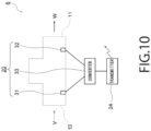
- FIG. 10 is a configuration diagram of a transmission unit 6 according to this embodiment.
- the transmission unit 6 has a temperature measurer 20 and a transmitter 24, as in the first embodiment.
- the temperature measurer 20 comprises a first thermometer 31, a second thermometer 32, and a converter 33.
- the first thermometer 31 and the second thermometer 32 are, for example, thermocouples that generate electromotive force corresponding to temperature, and are fixed to a supply portion 10 and a discharge portion 11, respectively.
- the converter 33 converts the electromotive forces generated by the thermometers 31 and 32 into temperatures, and notifies the transmitter 24 of them as temperature information.
- the transmitter 24 wirelessly transmits the temperature information to a receiver 7 (see FIG. 1 ).
- thermometers 31 and 32 In the case of using these thermometers 31 and 32 too, a determiner 8 determines whether an abnormality is present in accordance with the determination table in FIG. 9 , and a notifier 9 can issue a notice if an abnormality is present.
- the nozzle steam trap 3 it is possible to detect an abnormality in the steam trap 3 based solely on which temperature is higher, the temperature of each of the supply portion 10 and the discharge portion 11 or the corresponding reference temperature, without monitoring the changes over time in these temperatures.
- Such an advantage may be utilized such that, as described below, only the discharge portion 11 is provided with the second thermometer 32, and an abnormality in the steam trap 3 is detected based solely on the temperature of the discharge portion 11.
- FIGS. 11A and 11B are cross-sectional views of a steam trap 3 according to a modification of the second embodiment. The modification corresponds to claim 1.
- the abnormalities in FIGS. 11A and 11B can be detected even by providing only the discharge portion 11 with the second thermometer 32, as in this modification, and measuring only the temperature of the discharge portion 11.
- a first discharge-side reference temperature T e1 (e.g., 70°C to 90°C) lower than the boiling point T v of water may be set for the discharge portion 11 in advance.
- a second discharge-side reference temperature T e2 (e.g., 100°C to 120°C) higher than the boiling point T v of water may be set for the discharge portion 11 in advance.
- the first and second discharge-side reference temperatures T e1 and T e2 can be selected as appropriate according to the material of a pipe 5 and whether a heat insulating material is wound around the pipe 5.
- the determiner 8 may determine that an abnormality is present in the steam trap 3 when the temperature of the discharge portion 11 is lower than the first discharge-side reference temperature T e1 ( FIG. 11A ) or when this temperature of the discharge portion 11 is higher than the second discharge-side reference temperature T e2 ( FIG. 11B ).
- the temperature of each steam trap 3 is measured with an infrared sensor as below.
- FIG. 12 is a configuration diagram of a transmission unit 6 according to this embodiment.
- the transmission unit 6 has a temperature measurer 20 and a transmitter 24, as in the first embodiment and the second embodiment.
- the temperature measurer 20 comprises a first infrared sensor 41 and a second infrared sensor 42.
- the first infrared sensor 41 receives infrared rays emitted from a supply portion 10, and measures the temperature of the supply portion 10 based on these infrared rays.
- the second infrared sensor 42 receives infrared rays emitted from a discharge portion 11, and measures the temperature of the discharge portion 11 based on these infrared rays.
- the infrared sensors 41 and 42 then notify the transmitter 24 of the temperatures which they measured as temperature information.
- each of the infrared sensors 41 and 42 may be an infrared ray receiving element including only one pixel, or an infrared image sensor including a plurality of pixels.
- the transmitter 24 wirelessly transmits the temperature information to a receiver 7 (see FIG. 1 ).
- a determiner 8 determines whether an abnormality is present in accordance with the determination table in FIG. 9 , and a notifier 9 can issue a notice if an abnormality is present.
- nozzle steam traps are used as the steam traps 3.
- a mechanical steam trap including a mechanical movable portion as described below is used.
- FIG. 13 is a cross-sectional view of a steam trap 3 according to this reference example.
- This steam trap 3 is a float steam trap and includes a float 51 and a body 52 accommodating it.
- the body 52 is provided with a supply portion 10 into which water vapor V is supplied, and a discharge portion 11 which discharges liquid water W contained in the water vapor V.
- a portion inside the body 52 near the discharge portion 11 an arm 56 is provided which is freely pivotable about a fulcrum 55.
- the above-mentioned float 51 is fixed to one end of the arm 56. This makes the float 51 freely pivotable about the fulcrum 55. Furthermore, a valve body 57 is fixed to an intermediate portion of this arm 56, and a valve seat 58 provided in the discharge portion 11 is closed by the valve body 57.
- the steam trap 3 intermittently discharges the water W from the discharge portion 11 during a normal state.
- the intervals at which the water W is released depends on the specifications of the steam trap 3. For example, the water W is released from the steam trap 3 once every 5 seconds to 10 minutes.
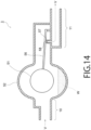
- FIG. 14 is a cross-sectional view of the steam trap 3 with an abnormality occurring therein.
- the level of the water W stored in the body 52 is low but a gap is formed between the valve body 57 and the valve seat 58 due to rust attached to them, so that the vapor V is leaking to the discharge portion 11 through this gap.
- the temperatures of the supply portion 10 and the discharge portion 11 do not change over time, and the supply portion 10 and the discharge portion 11 are both at substantially the same temperature as the vapor V.
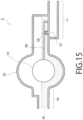
- FIG. 15 is a cross-sectional view of the steam trap 3 with a different abnormality from that in FIG. 14 occurring therein.
- the float 51 has stopped moving up or down for some reason, causing the valve body 57 to close the valve seat 58 all the time.
- the vapor V is not discharged to the discharge portion 11. Consequently, the discharge portion 11 is not heated by the vapor V, and the temperature of the discharge portion 11 falls over time as well.
- abnormalities can be detected by monitoring the changes over time in the temperatures of the supply portion 10 and the discharge portion 11.
- FIG. 16 is a configuration diagram of a transmission unit 6 according to this reference example.
- FIG. 16 Note that the same components in FIG. 16 as those described in the first to third embodiments are designated by the same reference signs as those in these embodiments, and description thereof is omitted below. This also applies to FIG. 17 to be mentioned later.
- the transmission unit 6 is provided with a first thermometer 31 and a second thermometer 32. Temperature information containing temperatures measured by these thermometers 31 and 32 is wirelessly transmitted from a transmitter 24.
- the temperatures of the steam trap 3 may be measured with the infrared sensors 41 and 42 described in the third embodiment (see FIG. 12 ).
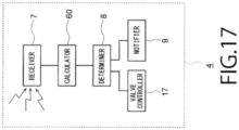
- FIG. 17 is a configuration diagram of the monitoring unit according to this reference example.
- a monitoring unit 4 includes a calculator 60 as well as the receiver 7, the determiner 8, the notifier 9, and the valve controller 17 described in the first embodiment.
- the receiver 7 receives the temperature information wirelessly transmitted from the transmission unit 6, and notifies the calculator 60 of the temperature information.
- the calculator 60 calculates an amount ⁇ T s of change over time in the temperature of the supply portion 10 in a predetermined time interval ⁇ t and an amount ⁇ T e of change over time in the temperature of the discharge portion 11 in the predetermined time interval ⁇ t.
- the time interval ⁇ t is not particularly limited. For example, it is a value of about 10 seconds to 30 seconds.
- the hardware configuration of the calculator 60 is not particularly limited either. Like the determiner 8, the calculator 60 is implemented with a processor such as a CPU and a memory cooperating with each other to execute a program.
- the determiner 8 determines whether an abnormality is present in the steam trap 3 based on the amounts ⁇ T s and ⁇ T e of changes over time in the temperatures calculated by the calculator 60.
- the criterion for this determination is selected as appropriate according to the abnormality to be detected.
- a first threshold value T 1 for temperature change is set in advance, and the determiner 8 determines that the abnormality is present if a state where the absolute values of the amounts ⁇ T s and ⁇ T e of changes over time in the temperatures are both lower than the first threshold value T 1 continues over a predetermined time period (e.g., 5 minutes to 10 minutes). Note that this time period is not limited to the above, and can be set as appropriate according to the position where the steam trap 3 is installed and the amount of liquid water W to be discharged from the steam trap 3.
- a second threshold value T 2 for determining that temperature changes are occurring in the negative direction is set in advance, and the determiner 8 determines that the abnormality is present if a state where the absolute values of the amounts ⁇ T s and ⁇ T e of changes over time in the temperatures of the supply portion 10 and the discharge portion 11 are lower than the second threshold value T 2 continues over a predetermined time period (e.g., 5 minutes to 10 minutes).
- This time period too is not limited to the above, and can be set as appropriate according to the position where the steam trap 3 is installed and the amount of liquid water W to be discharged from the steam trap 3.
- the notifier 9 issues a notice indicating that the abnormality is present in the steam trap 3.
- the valve controller 17 having received the result of the determination by the determiner 8 may open a release valve 16 (see FIG. 1 ) and release the water W from the release valve 16, as in the first embodiment.
- the mechanical steam trap is not limited to the float steam trap described above.
- any one of a bimetal steam trap 3, a bucket steam trap 3, and a disc steam trap 3 may be used.
- FIG. 18 is a cross-sectional view of the component according to this reference example.
- this component 70 has a steam trap 3, a first temperature indicator 21, and a second temperature indicator 22.
- the steam trap 3 is the nozzle steam trap described in the first embodiment.
- first temperature indicator 21 is a piece of temperature indicating tape attached to the supply portion 10 of the steam trap 3, and changes its color at the first reference temperature T 1 described in the first embodiment.
- second temperature indicator 22 is a piece of temperature indicating tape attached to the discharge portion 11 of the steam trap 3, and changes its color at the second reference temperature T 2 described in the first embodiment.
- a worker visually observes the color of the first temperature indicator 21, and the worker figures out whether the temperature of the supply portion 10 is higher than the first reference temperature T 1 based on this color.
- the worker visually observes the color of the second temperature indicator 22 as well, and the worker figures out whether the temperature of the discharge portion 11 is higher than the second reference temperature T 2 based on this color.
- the worker refers to the table in FIG. 9 and determines whether an abnormality is present in the steam trap 3.
- a worker can easily determine whether an abnormality is present in the steam trap 3 only by observing the colors of the temperature indicators 21 and 22, without having to bring a thermometer into contact with the steam trap 3. This can reduce the burden on the worker.
Landscapes
- Engineering & Computer Science (AREA)
- General Engineering & Computer Science (AREA)
- Physics & Mathematics (AREA)
- General Physics & Mathematics (AREA)
- Spectroscopy & Molecular Physics (AREA)
- Mechanical Engineering (AREA)
- Testing Of Devices, Machine Parts, Or Other Structures Thereof (AREA)
- Pipeline Systems (AREA)
- Testing And Monitoring For Control Systems (AREA)
Claims (7)
- Überwachungssystem (1), umfassend:einen Düsen-Kondensatableiter (3), der einen Zuführabschnitt (10), in den Wasserdampf zugeführt wird, und einem Auslassabschnitt (11), der flüssiges Wasser abführt, welches in dem Wasserdampf enthalten ist, umfasst,einen Temperaturmesser (20), der eine Temperatur des Auslassabschnitts misst,einen Sender (24), der Temperaturinformationen, die die von dem Temperaturmesser gemessene Temperatur enthalten, sendet,einen Empfänger (7), der die Temperaturinformationen empfängt,eine Bestimmungsvorrichtung (8), die auf Basis der Temperaturinformationen bestimmt, ob eine Anomalie in dem Düsen-Kondensatableiter vorhanden ist, undeine Benachrichtigungsvorrichtung (9), die eine Benachrichtigung ausgibt, wenn die Bestimmungsvorrichtung feststellt, dass die Anomalie vorhanden ist,wobei der Düsen-Kondensatableiter Folgendes aufweist:eine Düse (14), die ein Düsenloch (14a), aus dem der Wasserdampf und das flüssige Wasser ausgestoßen werden, umfasst,einen Wasserspeicherabschnitt (3d), der das aus dem Düsenloch ausgestoßene flüssige Wasser speichert und eine Öffnung (3e) umfasst, undeinen Kanal (3g), der das flüssige Wasser von der Öffnung zu dem Auslassabschnitt leitet, undwobei, wenn eine erste auslassseitige Referenztemperatur (Te1), die niedriger als ein Siedepunkt des Wassers ist, und eine zweite auslassseitige Referenztemperatur (Te2), die höher als der Siedepunkt des Wassers für den Auslassabschnitt ist, eingestellt sind, die Bestimmungsvorrichtung bestimmt, dass die Anomalie vorliegt, wenn die in den Temperaturinformationen enthaltene Temperatur des Auslassabschnitts niedriger als die erste auslassseitige Referenztemperatur oder höher als die zweite auslassseitige Referenztemperatur ist.
- Überwachungssystem gemäß Anspruch 1, wobeider Temperaturmesser einen Temperaturindikator (22) aufweist, der seine Farbe bei Referenztemperaturen, die die erste auslassseitige Referenztemperatur und die zweite auslassseitige Referenztemperatur umfassen, ändert, unddie Temperaturinformationen Informationen bezüglich der Farbe des Temperaturindikators sind.
- Überwachungssystem gemäß Anspruch 1, wobei der Temperaturmesser einen Infrarotsensor (42) aufweist, der einen von dem Auslassabschnitt emittierten Infrarotstrahl empfängt und die Temperatur basierend auf dem Infrarotstrahl misst.
- Überwachungssystem gemäß Anspruch 1, wobei der Temperaturmesser ein Thermometer (32), das an dem Auslassabschnitt befestigt ist und die Temperatur misst, aufweist.
- Überwachungssystem gemäß einem der Ansprüche 1 bis 4, wobeider Temperaturmesser ferner eine Temperatur des Zuführabschnitts misst,
unddie Bestimmungsvorrichtung ferner bestimmt, ob eine Anomalie vorliegt, basierend darauf, ob (oder ob nicht) die in den Temperaturinformationen enthaltene und durch den Temperaturmesser gemessene Temperatur des Zuführabschnitts niedriger ist als eine Referenztemperatur, die im Vorhinein für den Zuführabschnitt eingestellt ist. - Überwachungssystem gemäß einem der Ansprüche 1 bis 5, das ferner einen Rechner (60) umfasst, der einen Umfang der Änderung über die Zeit bei der in den Temperaturinformationen enthaltenen Temperatur berechnet,
wobei die Bestimmungsvorrichtung des Weiteren basierend auf dem vom Rechner berechneten Umfang der Änderung über die Zeit bestimmt, ob die Abnormalität vorliegt. - Überwachungssystem gemäß einem der Ansprüche 1 bis 6, ferner umfassend:eine Rohrleitung (5), die mit dem Zuführabschnitt verbunden ist,ein Ablassventil (16), das an der Rohrleitung vorgesehen ist, undeine Ventilsteuerung (17), die, wenn die Bestimmungsvorrichtung feststellt, dass die Anomalie vorhanden ist, das Ablassventil steuert, um das flüssige Wasser durch das Ablassventil zu einer Außenseite der Rohrleitung abzulassen.
Applications Claiming Priority (2)
| Application Number | Priority Date | Filing Date | Title |
|---|---|---|---|
| JP2018079460A JP6531310B1 (ja) | 2018-04-17 | 2018-04-17 | 監視システム |
| PCT/JP2019/016341 WO2019203235A1 (ja) | 2018-04-17 | 2019-04-16 | 監視システム |
Publications (3)
| Publication Number | Publication Date |
|---|---|
| EP3783253A1 EP3783253A1 (de) | 2021-02-24 |
| EP3783253A4 EP3783253A4 (de) | 2021-06-09 |
| EP3783253B1 true EP3783253B1 (de) | 2023-06-28 |
Family
ID=66934274
Family Applications (1)
| Application Number | Title | Priority Date | Filing Date |
|---|---|---|---|
| EP19789475.1A Active EP3783253B1 (de) | 2018-04-17 | 2019-04-16 | Überwachungssystem |
Country Status (5)
| Country | Link |
|---|---|
| US (1) | US11821583B2 (de) |
| EP (1) | EP3783253B1 (de) |
| JP (1) | JP6531310B1 (de) |
| CN (1) | CN112005043B (de) |
| WO (1) | WO2019203235A1 (de) |
Families Citing this family (3)
| Publication number | Priority date | Publication date | Assignee | Title |
|---|---|---|---|---|
| EP4040878A4 (de) | 2019-10-04 | 2022-11-09 | Panasonic Intellectual Property Corporation of America | Endgerät und kommunikationsverfahren |
| CN112945389B (zh) * | 2021-01-29 | 2023-10-31 | 华中科技大学 | 一种涡轮机末级动叶片温度的非接触式测量系统及方法 |
| JP7827343B1 (ja) * | 2025-10-27 | 2026-03-10 | ゼットエンジニアリング株式会社 | 判定装置、判定プログラム、判定方法及び判定システム |
Family Cites Families (61)
| Publication number | Priority date | Publication date | Assignee | Title |
|---|---|---|---|---|
| US2051732A (en) * | 1933-06-03 | 1936-08-18 | John F Mckee | Steam trap |
| US2936772A (en) * | 1953-10-19 | 1960-05-17 | Yarnall Waring Co | Steam trap |
| US3162208A (en) * | 1961-11-30 | 1964-12-22 | Sarco Company Inc | Thermodynamic trap |
| US3302878A (en) * | 1965-11-30 | 1967-02-07 | Fujiwara Katsuji | Thermo-synchronous steam trap |
| JPS5115896B1 (de) * | 1967-09-05 | 1976-05-20 | ||
| US3512544A (en) * | 1967-11-01 | 1970-05-19 | Sarco Co | Thermodynamic steam trap |
| JPS5179025A (ja) * | 1974-12-30 | 1976-07-09 | Fushiman Co Ltd | Dorentoratsupu |
| JPS5332362Y2 (de) * | 1974-12-30 | 1978-08-11 | ||
| JPS51115327A (en) * | 1975-04-02 | 1976-10-09 | Mitsui Shipbuilding Eng | Float type steam trap |
| US4073306A (en) * | 1977-01-27 | 1978-02-14 | Yarway Corporation | Steam trap |
| US4171209A (en) * | 1977-02-07 | 1979-10-16 | Thermal Con-Serv Corp. | Apparatus for removing condensate from steam lines, and the like |
| JPS5590898U (de) * | 1978-12-18 | 1980-06-23 | ||
| US4426213A (en) * | 1980-11-17 | 1984-01-17 | Engineering Resources, Inc. | Condensate removal device for steam lines and the like |
| JPS6121941U (ja) * | 1984-07-13 | 1986-02-08 | 株式会社 テイエルブイ | 作動判定機能を有するスチームトラップ配管 |
| US4745943A (en) * | 1987-04-28 | 1988-05-24 | Mortensen Erik M | Continuous flow steam condensate removal device |
| US4764024A (en) * | 1987-05-04 | 1988-08-16 | The United States Of America As Represented By The United States Department Of Energy | Steam trap monitor |
| US5120336A (en) * | 1988-09-12 | 1992-06-09 | Leblanc Thomas F | Flow constriction device in radiator steam trap |
| US5060686A (en) * | 1989-12-27 | 1991-10-29 | Engineering Resources, Inc. | Multi-piece nozzle for steam condensate removal devices |
| JPH0788920B2 (ja) * | 1990-09-14 | 1995-09-27 | 株式会社テイエルブイ | スチームトラップ装置 |
| US5137556A (en) * | 1991-06-11 | 1992-08-11 | Accu-Flow Tech, Inc. | Steam condensate drainage device for a steam piping system |
| JP2835669B2 (ja) * | 1992-10-15 | 1998-12-14 | 株式会社テイエルブイ | スチ―ムトラップの作動判定装置 |
| US5335686A (en) * | 1993-08-18 | 1994-08-09 | Isringhausen Carl L | Steam trap |
| US5632300A (en) * | 1993-08-18 | 1997-05-27 | Steamsphere Inc. | Steam trap |
| ES2127122B1 (es) * | 1996-09-02 | 1999-12-16 | Blaquez Navarro Vicente | Sistema mejorado electronico autonomo de monitorizacion para purgadores, valvulas e instalaciones en tiempo real. |
| JP3954672B2 (ja) * | 1996-10-14 | 2007-08-08 | 財団法人鉄道総合技術研究所 | 温度管理装置及びこれを用いた温度管理方法 |
| JP3862791B2 (ja) * | 1996-10-15 | 2006-12-27 | 株式会社テイエルブイ | 熱応動式スチ―ムトラップ |
| US7155363B1 (en) * | 1997-12-01 | 2006-12-26 | Mks Instruments, Inc. | Thermal imaging for semiconductor process monitoring |
| GB2332262A (en) * | 1997-12-11 | 1999-06-16 | Spirax Sarco Ltd | Monitoring condensate traps |
| US6148844A (en) * | 1998-07-01 | 2000-11-21 | Steam Tech, Inc. | Condensate removal device |
| JP2954183B1 (ja) | 1998-07-17 | 1999-09-27 | 株式会社ミヤワキ | スチームトラップの検査方法、同検査装置及び同管理システム |
| JP4041265B2 (ja) | 2000-05-09 | 2008-01-30 | 株式会社ミヤワキ | スチームトラップ管理装置 |
| JP3707994B2 (ja) * | 2000-05-15 | 2005-10-19 | 株式会社ミヤワキ | 赤外線温度検出器及びスチームトラップ検査装置 |
| JP4530507B2 (ja) * | 2000-09-01 | 2010-08-25 | 株式会社テイエルブイ | 蒸気トラップ診断装置、及び、蒸気トラップ診断方法 |
| JP3987707B2 (ja) * | 2001-10-29 | 2007-10-10 | 株式会社テイエルブイ | 蒸気トラップ監視装置 |
| JP2005515425A (ja) * | 2001-12-26 | 2005-05-26 | ボルテック インダストリーズ リミテッド | 温度測定および熱処理方法およびシステム |
| JP4563068B2 (ja) * | 2004-04-15 | 2010-10-13 | 株式会社テイエルブイ | 温度表示器 |
| KR100629440B1 (ko) * | 2004-10-08 | 2006-09-27 | 박동철 | 온도센서를 이용한 스팀트랩 |
| US7316241B1 (en) * | 2005-01-27 | 2008-01-08 | Spirax Sarco, Inc. | Steam trap |
| JP4953739B2 (ja) * | 2006-09-08 | 2012-06-13 | 中国電力株式会社 | サーモラベル付きドレントラップ及びドレントラップの点検方法 |
| US8050875B2 (en) * | 2006-12-26 | 2011-11-01 | Rosemount Inc. | Steam trap monitoring |
| US20090044867A1 (en) * | 2007-08-14 | 2009-02-19 | Ying Chuan Chiang | Mechanism for facilitating cleaning of filter of steam trap without shutting down boiler |
| JP5253919B2 (ja) * | 2008-08-12 | 2013-07-31 | 株式会社テイエルブイ | 温調トラップの診断装置 |
| GB201012465D0 (en) * | 2010-07-26 | 2010-09-08 | Mcfeeters Kenneth | Temperature monitoring apparatus for a steam trap |
| JP5715813B2 (ja) * | 2010-12-15 | 2015-05-13 | 株式会社テイエルブイ | 弁類の作動状態検出装置 |
| JP2013064434A (ja) * | 2011-09-16 | 2013-04-11 | Tlv Co Ltd | 熱応動式スチームトラップ |
| US9863836B2 (en) * | 2011-12-30 | 2018-01-09 | Spirax-Sarco Limited | Monitoring apparatus for a steam plant and a method of operating such an apparatus |
| WO2014025246A1 (en) * | 2012-08-09 | 2014-02-13 | Tan Sing Hong | A steam condensate drainer |
| US10641412B2 (en) * | 2012-09-28 | 2020-05-05 | Rosemount Inc. | Steam trap monitor with diagnostics |
| JP2014196783A (ja) * | 2013-03-29 | 2014-10-16 | 株式会社テイエルブイ | 温度表示装置 |
| JP3184441U (ja) * | 2013-04-16 | 2013-06-27 | 威唐企業有限公司 | スチームトラップ |
| JP2014234868A (ja) * | 2013-06-03 | 2014-12-15 | 株式会社スチームテック | スチームトラップ |
| EP3029368B1 (de) | 2013-08-02 | 2018-12-19 | Eco First Co. Ltd. | Kondensatableiterdüse |
| JP5680784B1 (ja) * | 2014-08-04 | 2015-03-04 | 株式会社テイエルブイ | 蒸気利用設備の管理方法、及び、蒸気利用設備 |
| KR101570659B1 (ko) * | 2014-09-11 | 2015-11-23 | 오순웅 | 스팀트랩의 생증기 누출체크장치 |
| JP5745149B1 (ja) * | 2014-10-10 | 2015-07-08 | 有限会社ジェニス・ホワイト | 凝縮水排出装置 |
| JP6630488B2 (ja) * | 2015-04-17 | 2020-01-15 | 株式会社テイエルブイ | 判定器、及び、判定方法 |
| EP3299917A4 (de) | 2015-05-18 | 2018-03-28 | TLV Co., Ltd. | Vorrichtungsverwaltungssystem und vorrichtungsverwaltungsverfahren |
| EP3441663A4 (de) * | 2016-04-04 | 2019-11-27 | Eco First Co. Ltd. | Kondensatableiter vom düsentyp |
| JP6654100B2 (ja) * | 2016-05-25 | 2020-02-26 | 株式会社テイエルブイ | ドレントラップの診断装置およびドレントラップ |
| WO2019197945A1 (en) * | 2018-04-09 | 2019-10-17 | Velan Inc. | Electronic steam trap |
| MY209757A (en) * | 2019-01-31 | 2025-07-31 | Tlv Co Ltd | Monitoring system, monitoring method and monitoring program for steam-using equipment |
-
2018
- 2018-04-17 JP JP2018079460A patent/JP6531310B1/ja active Active
-
2019
- 2019-04-16 EP EP19789475.1A patent/EP3783253B1/de active Active
- 2019-04-16 WO PCT/JP2019/016341 patent/WO2019203235A1/ja not_active Ceased
- 2019-04-16 CN CN201980026067.3A patent/CN112005043B/zh active Active
-
2020
- 2020-10-14 US US17/069,993 patent/US11821583B2/en active Active
Also Published As
| Publication number | Publication date |
|---|---|
| US11821583B2 (en) | 2023-11-21 |
| EP3783253A4 (de) | 2021-06-09 |
| JP6531310B1 (ja) | 2019-06-19 |
| WO2019203235A1 (ja) | 2019-10-24 |
| JP2019184041A (ja) | 2019-10-24 |
| US20210071814A1 (en) | 2021-03-11 |
| CN112005043A (zh) | 2020-11-27 |
| CN112005043B (zh) | 2024-05-28 |
| EP3783253A1 (de) | 2021-02-24 |
Similar Documents
| Publication | Publication Date | Title |
|---|---|---|
| US11821583B2 (en) | Monitoring system | |
| EP1388281B1 (de) | Vorrichtung für die Überwachung eines Milchbehälters, und Anordnung von einem Melkroboter mit einer automatischen Anfahreinheit und von einer solchen Vorrichtung | |
| CN105209902B (zh) | 用于原位测量腐蚀的方法和系统 | |
| JP4740855B2 (ja) | 構造体の欠陥を監視するためのシステム及び方法 | |
| CN106969885B (zh) | 一种发电厂凝汽器泄漏检测系统及检测方法 | |
| US20200340220A1 (en) | Leak Detection Method and Apparatus | |
| US11299871B2 (en) | Leak detection method and apparatus | |
| KR101578126B1 (ko) | 멀티어플리케이션 오리피스 스팀트랩 장치 | |
| KR101927459B1 (ko) | 색 분석 카메라 인식기능을 이용한 배관 누수 모니터링 시스템 및 그를 이용한 배관 누수 모니터링 방법 | |
| US9322487B2 (en) | Nuclear grade air accumulation, indication and venting device | |
| KR101104882B1 (ko) | 고온 유체 배관류 및 연결부의 누설 탐지방법 | |
| CN205199499U (zh) | 及时监测泄漏的反应装置 | |
| US10702129B2 (en) | Method for processing an endoscope | |
| JP2009287201A (ja) | 観測システム | |
| US8505568B2 (en) | Nuclear grade air accumulation, indication and venting device | |
| JP5475076B2 (ja) | 水位変化検出機能付残留塩素計 | |
| RU95403U1 (ru) | Кондуктометрический сигнализатор наличия жидкости в паре | |
| US10054512B2 (en) | Leak indicator | |
| CN208751622U (zh) | 一种医疗污水排放监控系统 | |
| GB2496890A (en) | Corrosion detector | |
| EP3120131B1 (de) | Korrosionssensor für wärmetauscher | |
| KR102951981B1 (ko) | 원격모니터링 다중센서를 이용한 스마트 스팀트랩 | |
| KR100873202B1 (ko) | 반도체 장비용 냉각수 누수 감지장치 | |
| HK40063604B (zh) | 水质监测系统 |
Legal Events
| Date | Code | Title | Description |
|---|---|---|---|
| STAA | Information on the status of an ep patent application or granted ep patent |
Free format text: STATUS: THE INTERNATIONAL PUBLICATION HAS BEEN MADE |
|
| PUAI | Public reference made under article 153(3) epc to a published international application that has entered the european phase |
Free format text: ORIGINAL CODE: 0009012 |
|
| STAA | Information on the status of an ep patent application or granted ep patent |
Free format text: STATUS: REQUEST FOR EXAMINATION WAS MADE |
|
| 17P | Request for examination filed |
Effective date: 20201110 |
|
| AK | Designated contracting states |
Kind code of ref document: A1 Designated state(s): AL AT BE BG CH CY CZ DE DK EE ES FI FR GB GR HR HU IE IS IT LI LT LU LV MC MK MT NL NO PL PT RO RS SE SI SK SM TR |
|
| AX | Request for extension of the european patent |
Extension state: BA ME |
|
| A4 | Supplementary search report drawn up and despatched |
Effective date: 20210511 |
|
| RIC1 | Information provided on ipc code assigned before grant |
Ipc: F16T 1/48 20060101AFI20210504BHEP Ipc: F16T 1/00 20060101ALI20210504BHEP |
|
| DAV | Request for validation of the european patent (deleted) | ||
| DAX | Request for extension of the european patent (deleted) | ||
| GRAP | Despatch of communication of intention to grant a patent |
Free format text: ORIGINAL CODE: EPIDOSNIGR1 |
|
| STAA | Information on the status of an ep patent application or granted ep patent |
Free format text: STATUS: GRANT OF PATENT IS INTENDED |
|
| INTG | Intention to grant announced |
Effective date: 20230112 |
|
| GRAS | Grant fee paid |
Free format text: ORIGINAL CODE: EPIDOSNIGR3 |
|
| GRAA | (expected) grant |
Free format text: ORIGINAL CODE: 0009210 |
|
| STAA | Information on the status of an ep patent application or granted ep patent |
Free format text: STATUS: THE PATENT HAS BEEN GRANTED |
|
| AK | Designated contracting states |
Kind code of ref document: B1 Designated state(s): AL AT BE BG CH CY CZ DE DK EE ES FI FR GB GR HR HU IE IS IT LI LT LU LV MC MK MT NL NO PL PT RO RS SE SI SK SM TR |
|
| REG | Reference to a national code |
Ref country code: CH Ref legal event code: EP |
|
| REG | Reference to a national code |
Ref country code: AT Ref legal event code: REF Ref document number: 1582961 Country of ref document: AT Kind code of ref document: T Effective date: 20230715 |
|
| REG | Reference to a national code |
Ref country code: IE Ref legal event code: FG4D |
|
| REG | Reference to a national code |
Ref country code: DE Ref legal event code: R096 Ref document number: 602019031814 Country of ref document: DE |
|
| REG | Reference to a national code |
Ref country code: LT Ref legal event code: MG9D |
|
| PG25 | Lapsed in a contracting state [announced via postgrant information from national office to epo] |
Ref country code: SE Free format text: LAPSE BECAUSE OF FAILURE TO SUBMIT A TRANSLATION OF THE DESCRIPTION OR TO PAY THE FEE WITHIN THE PRESCRIBED TIME-LIMIT Effective date: 20230628 Ref country code: NO Free format text: LAPSE BECAUSE OF FAILURE TO SUBMIT A TRANSLATION OF THE DESCRIPTION OR TO PAY THE FEE WITHIN THE PRESCRIBED TIME-LIMIT Effective date: 20230928 |
|
| REG | Reference to a national code |
Ref country code: NL Ref legal event code: MP Effective date: 20230628 |
|
| REG | Reference to a national code |
Ref country code: AT Ref legal event code: MK05 Ref document number: 1582961 Country of ref document: AT Kind code of ref document: T Effective date: 20230628 |
|
| PG25 | Lapsed in a contracting state [announced via postgrant information from national office to epo] |
Ref country code: RS Free format text: LAPSE BECAUSE OF FAILURE TO SUBMIT A TRANSLATION OF THE DESCRIPTION OR TO PAY THE FEE WITHIN THE PRESCRIBED TIME-LIMIT Effective date: 20230628 Ref country code: NL Free format text: LAPSE BECAUSE OF FAILURE TO SUBMIT A TRANSLATION OF THE DESCRIPTION OR TO PAY THE FEE WITHIN THE PRESCRIBED TIME-LIMIT Effective date: 20230628 Ref country code: LV Free format text: LAPSE BECAUSE OF FAILURE TO SUBMIT A TRANSLATION OF THE DESCRIPTION OR TO PAY THE FEE WITHIN THE PRESCRIBED TIME-LIMIT Effective date: 20230628 Ref country code: LT Free format text: LAPSE BECAUSE OF FAILURE TO SUBMIT A TRANSLATION OF THE DESCRIPTION OR TO PAY THE FEE WITHIN THE PRESCRIBED TIME-LIMIT Effective date: 20230628 Ref country code: HR Free format text: LAPSE BECAUSE OF FAILURE TO SUBMIT A TRANSLATION OF THE DESCRIPTION OR TO PAY THE FEE WITHIN THE PRESCRIBED TIME-LIMIT Effective date: 20230628 Ref country code: GR Free format text: LAPSE BECAUSE OF FAILURE TO SUBMIT A TRANSLATION OF THE DESCRIPTION OR TO PAY THE FEE WITHIN THE PRESCRIBED TIME-LIMIT Effective date: 20230929 |
|
| PG25 | Lapsed in a contracting state [announced via postgrant information from national office to epo] |
Ref country code: FI Free format text: LAPSE BECAUSE OF FAILURE TO SUBMIT A TRANSLATION OF THE DESCRIPTION OR TO PAY THE FEE WITHIN THE PRESCRIBED TIME-LIMIT Effective date: 20230628 |
|
| PG25 | Lapsed in a contracting state [announced via postgrant information from national office to epo] |
Ref country code: SK Free format text: LAPSE BECAUSE OF FAILURE TO SUBMIT A TRANSLATION OF THE DESCRIPTION OR TO PAY THE FEE WITHIN THE PRESCRIBED TIME-LIMIT Effective date: 20230628 |
|
| PG25 | Lapsed in a contracting state [announced via postgrant information from national office to epo] |
Ref country code: ES Free format text: LAPSE BECAUSE OF FAILURE TO SUBMIT A TRANSLATION OF THE DESCRIPTION OR TO PAY THE FEE WITHIN THE PRESCRIBED TIME-LIMIT Effective date: 20230628 |
|
| PG25 | Lapsed in a contracting state [announced via postgrant information from national office to epo] |
Ref country code: IS Free format text: LAPSE BECAUSE OF FAILURE TO SUBMIT A TRANSLATION OF THE DESCRIPTION OR TO PAY THE FEE WITHIN THE PRESCRIBED TIME-LIMIT Effective date: 20231028 |
|
| PG25 | Lapsed in a contracting state [announced via postgrant information from national office to epo] |
Ref country code: SM Free format text: LAPSE BECAUSE OF FAILURE TO SUBMIT A TRANSLATION OF THE DESCRIPTION OR TO PAY THE FEE WITHIN THE PRESCRIBED TIME-LIMIT Effective date: 20230628 Ref country code: SK Free format text: LAPSE BECAUSE OF FAILURE TO SUBMIT A TRANSLATION OF THE DESCRIPTION OR TO PAY THE FEE WITHIN THE PRESCRIBED TIME-LIMIT Effective date: 20230628 Ref country code: RO Free format text: LAPSE BECAUSE OF FAILURE TO SUBMIT A TRANSLATION OF THE DESCRIPTION OR TO PAY THE FEE WITHIN THE PRESCRIBED TIME-LIMIT Effective date: 20230628 Ref country code: PT Free format text: LAPSE BECAUSE OF FAILURE TO SUBMIT A TRANSLATION OF THE DESCRIPTION OR TO PAY THE FEE WITHIN THE PRESCRIBED TIME-LIMIT Effective date: 20231030 Ref country code: IS Free format text: LAPSE BECAUSE OF FAILURE TO SUBMIT A TRANSLATION OF THE DESCRIPTION OR TO PAY THE FEE WITHIN THE PRESCRIBED TIME-LIMIT Effective date: 20231028 Ref country code: ES Free format text: LAPSE BECAUSE OF FAILURE TO SUBMIT A TRANSLATION OF THE DESCRIPTION OR TO PAY THE FEE WITHIN THE PRESCRIBED TIME-LIMIT Effective date: 20230628 Ref country code: EE Free format text: LAPSE BECAUSE OF FAILURE TO SUBMIT A TRANSLATION OF THE DESCRIPTION OR TO PAY THE FEE WITHIN THE PRESCRIBED TIME-LIMIT Effective date: 20230628 Ref country code: CZ Free format text: LAPSE BECAUSE OF FAILURE TO SUBMIT A TRANSLATION OF THE DESCRIPTION OR TO PAY THE FEE WITHIN THE PRESCRIBED TIME-LIMIT Effective date: 20230628 Ref country code: AT Free format text: LAPSE BECAUSE OF FAILURE TO SUBMIT A TRANSLATION OF THE DESCRIPTION OR TO PAY THE FEE WITHIN THE PRESCRIBED TIME-LIMIT Effective date: 20230628 |
|
| PG25 | Lapsed in a contracting state [announced via postgrant information from national office to epo] |
Ref country code: PL Free format text: LAPSE BECAUSE OF FAILURE TO SUBMIT A TRANSLATION OF THE DESCRIPTION OR TO PAY THE FEE WITHIN THE PRESCRIBED TIME-LIMIT Effective date: 20230628 |
|
| REG | Reference to a national code |
Ref country code: DE Ref legal event code: R097 Ref document number: 602019031814 Country of ref document: DE |
|
| PG25 | Lapsed in a contracting state [announced via postgrant information from national office to epo] |
Ref country code: DK Free format text: LAPSE BECAUSE OF FAILURE TO SUBMIT A TRANSLATION OF THE DESCRIPTION OR TO PAY THE FEE WITHIN THE PRESCRIBED TIME-LIMIT Effective date: 20230628 |
|
| PLBE | No opposition filed within time limit |
Free format text: ORIGINAL CODE: 0009261 |
|
| STAA | Information on the status of an ep patent application or granted ep patent |
Free format text: STATUS: NO OPPOSITION FILED WITHIN TIME LIMIT |
|
| PG25 | Lapsed in a contracting state [announced via postgrant information from national office to epo] |
Ref country code: IT Free format text: LAPSE BECAUSE OF FAILURE TO SUBMIT A TRANSLATION OF THE DESCRIPTION OR TO PAY THE FEE WITHIN THE PRESCRIBED TIME-LIMIT Effective date: 20230628 |
|
| 26N | No opposition filed |
Effective date: 20240402 |
|
| PG25 | Lapsed in a contracting state [announced via postgrant information from national office to epo] |
Ref country code: SI Free format text: LAPSE BECAUSE OF FAILURE TO SUBMIT A TRANSLATION OF THE DESCRIPTION OR TO PAY THE FEE WITHIN THE PRESCRIBED TIME-LIMIT Effective date: 20230628 |
|
| PG25 | Lapsed in a contracting state [announced via postgrant information from national office to epo] |
Ref country code: BG Free format text: LAPSE BECAUSE OF FAILURE TO SUBMIT A TRANSLATION OF THE DESCRIPTION OR TO PAY THE FEE WITHIN THE PRESCRIBED TIME-LIMIT Effective date: 20230628 |
|
| PG25 | Lapsed in a contracting state [announced via postgrant information from national office to epo] |
Ref country code: MC Free format text: LAPSE BECAUSE OF FAILURE TO SUBMIT A TRANSLATION OF THE DESCRIPTION OR TO PAY THE FEE WITHIN THE PRESCRIBED TIME-LIMIT Effective date: 20230628 |
|
| PG25 | Lapsed in a contracting state [announced via postgrant information from national office to epo] |
Ref country code: MC Free format text: LAPSE BECAUSE OF FAILURE TO SUBMIT A TRANSLATION OF THE DESCRIPTION OR TO PAY THE FEE WITHIN THE PRESCRIBED TIME-LIMIT Effective date: 20230628 Ref country code: BG Free format text: LAPSE BECAUSE OF FAILURE TO SUBMIT A TRANSLATION OF THE DESCRIPTION OR TO PAY THE FEE WITHIN THE PRESCRIBED TIME-LIMIT Effective date: 20230628 |
|
| REG | Reference to a national code |
Ref country code: CH Ref legal event code: PL |
|
| PG25 | Lapsed in a contracting state [announced via postgrant information from national office to epo] |
Ref country code: LU Free format text: LAPSE BECAUSE OF NON-PAYMENT OF DUE FEES Effective date: 20240416 |
|
| REG | Reference to a national code |
Ref country code: BE Ref legal event code: MM Effective date: 20240430 |
|
| PG25 | Lapsed in a contracting state [announced via postgrant information from national office to epo] |
Ref country code: LU Free format text: LAPSE BECAUSE OF NON-PAYMENT OF DUE FEES Effective date: 20240416 |
|
| PG25 | Lapsed in a contracting state [announced via postgrant information from national office to epo] |
Ref country code: BE Free format text: LAPSE BECAUSE OF NON-PAYMENT OF DUE FEES Effective date: 20240430 |
|
| PG25 | Lapsed in a contracting state [announced via postgrant information from national office to epo] |
Ref country code: BE Free format text: LAPSE BECAUSE OF NON-PAYMENT OF DUE FEES Effective date: 20240430 Ref country code: CH Free format text: LAPSE BECAUSE OF NON-PAYMENT OF DUE FEES Effective date: 20240430 |
|
| PG25 | Lapsed in a contracting state [announced via postgrant information from national office to epo] |
Ref country code: IE Free format text: LAPSE BECAUSE OF NON-PAYMENT OF DUE FEES Effective date: 20240416 |
|
| PGFP | Annual fee paid to national office [announced via postgrant information from national office to epo] |
Ref country code: DE Payment date: 20250422 Year of fee payment: 7 |
|
| PGFP | Annual fee paid to national office [announced via postgrant information from national office to epo] |
Ref country code: GB Payment date: 20250423 Year of fee payment: 7 |
|
| PGFP | Annual fee paid to national office [announced via postgrant information from national office to epo] |
Ref country code: FR Payment date: 20250425 Year of fee payment: 7 |
|
| PG25 | Lapsed in a contracting state [announced via postgrant information from national office to epo] |
Ref country code: CY Free format text: LAPSE BECAUSE OF FAILURE TO SUBMIT A TRANSLATION OF THE DESCRIPTION OR TO PAY THE FEE WITHIN THE PRESCRIBED TIME-LIMIT; INVALID AB INITIO Effective date: 20190416 |
|
| PG25 | Lapsed in a contracting state [announced via postgrant information from national office to epo] |
Ref country code: HU Free format text: LAPSE BECAUSE OF FAILURE TO SUBMIT A TRANSLATION OF THE DESCRIPTION OR TO PAY THE FEE WITHIN THE PRESCRIBED TIME-LIMIT; INVALID AB INITIO Effective date: 20190416 |