EP3779314B1 - In eine raumdecke eingebettete klimaanlage - Google Patents
In eine raumdecke eingebettete klimaanlage Download PDFInfo
- Publication number
- EP3779314B1 EP3779314B1 EP19774994.8A EP19774994A EP3779314B1 EP 3779314 B1 EP3779314 B1 EP 3779314B1 EP 19774994 A EP19774994 A EP 19774994A EP 3779314 B1 EP3779314 B1 EP 3779314B1
- Authority
- EP
- European Patent Office
- Prior art keywords
- air
- heat exchange
- exchange part
- air blowing
- ceiling
- Prior art date
- Legal status (The legal status is an assumption and is not a legal conclusion. Google has not performed a legal analysis and makes no representation as to the accuracy of the status listed.)
- Active
Links
- 238000007664 blowing Methods 0.000 claims description 184
- 238000004378 air conditioning Methods 0.000 claims description 31
- 238000009423 ventilation Methods 0.000 claims description 24
- 238000005192 partition Methods 0.000 description 27
- 230000001143 conditioned effect Effects 0.000 description 11
- 239000003507 refrigerant Substances 0.000 description 6
- 239000011810 insulating material Substances 0.000 description 5
- PPBRXRYQALVLMV-UHFFFAOYSA-N Styrene Chemical compound C=CC1=CC=CC=C1 PPBRXRYQALVLMV-UHFFFAOYSA-N 0.000 description 4
- 229910052751 metal Inorganic materials 0.000 description 4
- 239000002184 metal Substances 0.000 description 4
- 230000002093 peripheral effect Effects 0.000 description 4
- 239000003566 sealing material Substances 0.000 description 4
- XLYOFNOQVPJJNP-UHFFFAOYSA-N water Substances O XLYOFNOQVPJJNP-UHFFFAOYSA-N 0.000 description 4
- 230000005494 condensation Effects 0.000 description 3
- 238000009833 condensation Methods 0.000 description 3
- 239000000835 fiber Substances 0.000 description 3
- 239000007788 liquid Substances 0.000 description 3
- 239000000463 material Substances 0.000 description 3
- 229920006324 polyoxymethylene Polymers 0.000 description 3
- 229930182556 Polyacetal Natural products 0.000 description 2
- 229910052782 aluminium Inorganic materials 0.000 description 2
- XAGFODPZIPBFFR-UHFFFAOYSA-N aluminium Chemical compound [Al] XAGFODPZIPBFFR-UHFFFAOYSA-N 0.000 description 2
- 238000001816 cooling Methods 0.000 description 2
- 239000006260 foam Substances 0.000 description 2
- 229920005989 resin Polymers 0.000 description 2
- 239000011347 resin Substances 0.000 description 2
- 230000000903 blocking effect Effects 0.000 description 1
- 230000007423 decrease Effects 0.000 description 1
- 230000000694 effects Effects 0.000 description 1
- 238000009434 installation Methods 0.000 description 1
- NJPPVKZQTLUDBO-UHFFFAOYSA-N novaluron Chemical compound C1=C(Cl)C(OC(F)(F)C(OC(F)(F)F)F)=CC=C1NC(=O)NC(=O)C1=C(F)C=CC=C1F NJPPVKZQTLUDBO-UHFFFAOYSA-N 0.000 description 1
- 238000004806 packaging method and process Methods 0.000 description 1
- 238000012856 packing Methods 0.000 description 1
- 229920003002 synthetic resin Polymers 0.000 description 1
- 239000000057 synthetic resin Substances 0.000 description 1
Images


Classifications
-
- F—MECHANICAL ENGINEERING; LIGHTING; HEATING; WEAPONS; BLASTING
- F24—HEATING; RANGES; VENTILATING
- F24F—AIR-CONDITIONING; AIR-HUMIDIFICATION; VENTILATION; USE OF AIR CURRENTS FOR SCREENING
- F24F1/00—Room units for air-conditioning, e.g. separate or self-contained units or units receiving primary air from a central station
- F24F1/0007—Indoor units, e.g. fan coil units
- F24F1/0043—Indoor units, e.g. fan coil units characterised by mounting arrangements
- F24F1/0047—Indoor units, e.g. fan coil units characterised by mounting arrangements mounted in the ceiling or at the ceiling
-
- F—MECHANICAL ENGINEERING; LIGHTING; HEATING; WEAPONS; BLASTING
- F24—HEATING; RANGES; VENTILATING
- F24F—AIR-CONDITIONING; AIR-HUMIDIFICATION; VENTILATION; USE OF AIR CURRENTS FOR SCREENING
- F24F1/00—Room units for air-conditioning, e.g. separate or self-contained units or units receiving primary air from a central station
- F24F1/0007—Indoor units, e.g. fan coil units
- F24F1/0011—Indoor units, e.g. fan coil units characterised by air outlets
- F24F1/0014—Indoor units, e.g. fan coil units characterised by air outlets having two or more outlet openings
-
- F—MECHANICAL ENGINEERING; LIGHTING; HEATING; WEAPONS; BLASTING
- F24—HEATING; RANGES; VENTILATING
- F24F—AIR-CONDITIONING; AIR-HUMIDIFICATION; VENTILATION; USE OF AIR CURRENTS FOR SCREENING
- F24F1/00—Room units for air-conditioning, e.g. separate or self-contained units or units receiving primary air from a central station
- F24F1/0007—Indoor units, e.g. fan coil units
- F24F1/0059—Indoor units, e.g. fan coil units characterised by heat exchangers
- F24F1/0063—Indoor units, e.g. fan coil units characterised by heat exchangers by the mounting or arrangement of the heat exchangers
-
- F—MECHANICAL ENGINEERING; LIGHTING; HEATING; WEAPONS; BLASTING
- F24—HEATING; RANGES; VENTILATING
- F24F—AIR-CONDITIONING; AIR-HUMIDIFICATION; VENTILATION; USE OF AIR CURRENTS FOR SCREENING
- F24F13/00—Details common to, or for air-conditioning, air-humidification, ventilation or use of air currents for screening
- F24F13/02—Ducting arrangements
- F24F13/06—Outlets for directing or distributing air into rooms or spaces, e.g. ceiling air diffuser
- F24F13/065—Outlets for directing or distributing air into rooms or spaces, e.g. ceiling air diffuser formed as cylindrical or spherical bodies which are rotatable
-
- F—MECHANICAL ENGINEERING; LIGHTING; HEATING; WEAPONS; BLASTING
- F24—HEATING; RANGES; VENTILATING
- F24F—AIR-CONDITIONING; AIR-HUMIDIFICATION; VENTILATION; USE OF AIR CURRENTS FOR SCREENING
- F24F13/00—Details common to, or for air-conditioning, air-humidification, ventilation or use of air currents for screening
- F24F13/20—Casings or covers
-
- F—MECHANICAL ENGINEERING; LIGHTING; HEATING; WEAPONS; BLASTING
- F24—HEATING; RANGES; VENTILATING
- F24F—AIR-CONDITIONING; AIR-HUMIDIFICATION; VENTILATION; USE OF AIR CURRENTS FOR SCREENING
- F24F13/00—Details common to, or for air-conditioning, air-humidification, ventilation or use of air currents for screening
- F24F13/22—Means for preventing condensation or evacuating condensate
- F24F13/222—Means for preventing condensation or evacuating condensate for evacuating condensate
Definitions
- the present invention relates to a ceiling-embedded air conditioner, and more particularly to the structure of an indoor unit.
- an outdoor unit installed outdoors and an indoor unit installed in a ceiling of an air conditioning room are connected by a gas pipe and a liquid pipe to form a refrigerant circuit.
- the indoor unit has a box-shaped main unit that is buried in the ceiling back space, and a decorative panel that is disposed on the air conditioning room side of the ceiling and attached to the main unit.
- a U-shaped heat exchanger in the main unit, a fan casing in the center of the heat exchanger, and a blowing fan formed of a sirocco fan surrounded by the fan casing are provided.
- the decorative panel has a blowing opening at the center and suction openings along three sides below the heat exchanger.
- the air sucked from the suction opening can exchange heat with the refrigerant in the heat exchanger and can be blown out in one direction from the blowing opening.
- the distance between the blowing fan and the surface of the heat exchanger is almost constant, and there is little bias in the wind speed and air volume of the air passing through the heat exchanger.
- the heat exchanger is used effectively so that the heat exchange performance can be increased.
- Patent Literature 2 discloses a ceiling-embedded air conditioner, comprising a box-shaped main unit that includes an air blower, a heat exchanger, and a drain pan and is disposable in a ceiling of an air conditioning room; and a decorative panel that is attached to a bottom surface of the main unit along a ceiling surface of the air conditioning room, the decorative panel being provided with an air suction part and an air blowing part, wherein the heat exchanger includes at least two heat exchange parts of a front heat exchange part and a rear heat exchange part, the front heat exchange part and the rear heat exchange part are disposed in the main unit so as to face each other, an air blowing chamber is provided between the front heat exchange part and the rear heat exchange part, a first air suction chamber is provided outside the rear heat exchange part, a second air suction chamber is provided outside the front heat exchange part, and the air suction part is disposed on a side of the first air suction chamber, and the air blower is housed in the air blowing chamber, a bottom surface of the air blowing chamber
- the air passage extending from the suction opening to the heat exchanger is preferably short in view of reducing ventilation resistance and designing the housing. Therefore, the heat exchanger is usually provided near the suction opening. Therefore, when disposing the heat exchanger around the blowing fan, the heat exchanger is not disposed on the air blowing direction side where it is not preferable to provide the suction opening. Improvement on this point has been desired in order to increase the heat exchange performance.
- an object of the invention is to provide a ceiling-embedded air conditioner with which, when the heat exchanger is disposed around the blowing fan, the heat exchanger can be disposed even at a place where the air suction opening cannot be provided.
- the invention provides a ceiling-embedded air conditioner which includes a box-shaped main unit that includes an air blower, a heat exchanger, and a drain pan and is disposable in a ceiling of an air conditioning room, and a decorative panel that is attached to a bottom surface of the main unit along a ceiling surface of the air conditioning room.
- the decorative panel is provided with an air suction part and an air blowing part.
- the heat exchanger includes at least two heat exchange parts of a front heat exchange part and a rear heat exchange part, the front heat exchange part and the rear heat exchange part are disposed in the main unit so as to face each other, an air blowing chamber is provided between the front heat exchange part and the rear heat exchange part, a first air suction chamber is provided outside the rear heat exchange part, a second air suction chamber is provided outside the front heat exchange part, and the air suction part is disposed on a side of the first air suction chamber.
- the air blower is housed in the air blowing chamber, a bottom surface of the air blowing chamber is closed by the drain pan, and an air guide path is formed from the air suction part to the second air suction chamber on a side of the front heat exchange part between the decorative panel and the drain pan.
- a ventilation hole is formed in the drain pan, a plurality of ducts is provided in the decorative panel to be fitted into the ventilation hole so as to guide air blown out from the air blower to the air blowing part, the air guide path is formed between the duct and the duct, and a recess is formed in a bottom surface of the drain pan corresponding to the air guide path to expand a cross-sectional area of the air guide path.
- the air blowing part includes a raised portion that projects toward the air conditioning room rather than a panel surface of the decorative panel, and is formed with an air blowing opening in a side surface of the raised portion to blow out air blown out from the air blower along the panel surface of the decorative panel.
- the air suction part is disposed so as to be included in the panel surface of the decorative panel above the raised portion when viewed from the air conditioning room.
- a distance from a rotating shaft that is the center of the air blower to the front heat exchange part is L1
- a distance from the rotating shaft that is the center of the air blower to the rear heat exchange part is L2
- L1 ⁇ L2 is satisfied.
- the air blower includes a fan motor, an impeller driven by the fan motor, and a fan casing surrounding the impeller, and a side of the fan casing that faces the front heat exchange part is formed in a horizontal plane.
- a distance between an upper end of the front heat exchange part and an upper end of the rear heat exchange part is larger than a distance between a lower end of the front heat exchange part and a lower end of the rear heat exchange part.
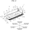
- An air conditioner according to the invention is a refrigerant circuit in which an outdoor unit (not illustrated) installed outdoors and an indoor unit 1 attached to a ceiling T1 of an air conditioning room R are connected by a gas pipe and a liquid pipe (both not illustrated).
- an indoor unit 1 is a ceiling-embedded air conditioner that includes a box-shaped main unit 10 embedded in a ceiling back space T2 and a decorative panel 70 that is disposed on the air conditioning room R side of the ceiling T1 and attached to a bottom surface 101 of the main unit 10, and particularly is an omnidirectional blow-out type ceiling-embedded air conditioner that blows out conditioned air over a wide range.
- the main unit 10 has a rectangular top plate 111 formed of sheet metal, and a box-shaped outer trunk 11 formed of side plates 112 and 113 extending downward from four sides of the top plate 111.
- the side plate on the long side of the top plate 111 is the side plate 112 and the side plate on the short side is the side plate 113, and two mounting brackets 12 are fixed to each of the two side plates 113 facing each other.
- the main unit 10 is installed on the ceiling back space T2 by suspending the mounting bracket 12 with a plurality of hanging bolts (not illustrated) fixed to the ceiling back space T2.
- the decorative panel 70 includes a panel portion 71 that forms the main body of the rectangular decorative panel 70 that is larger than the top plate 111, and a side wall 72 which is erected from the rear surface 70R of the panel portion 71 to the main unit 10 side and attached to the opened bottom surface (the bottom surface 101 of the main unit 10) of the box-shaped outer trunk 11.
- the panel portion 71 includes an air suction part 73 that is opened in a square shape on one side 70b located on the rear side among the facing long sides, and an air blowing part 74 on another side 70a that exists in front of the long side facing the side 70b.
- the top plate 111 direction will be described as the upper surface or the upper side, the air conditioning room R direction as the bottom surface or the lower side, the air blowing part 74 side as the front surface or the front side, and the air suction part 73 side as the back surface side or the rear side, the left short side 70c side as the left surface or the left side, and the right short side 70d side as the right surface or the right side.
- the air conditioning room R direction as the bottom surface or the lower side
- the air blowing part 74 side as the front surface or the front side
- the air suction part 73 side as the back surface side or the rear side
- the left short side 70c side as the left surface or the left side
- the right short side 70d side as the right surface or the right side.
- the side wall 72 includes a frame 721 which is formed in a rectangular shape along the respective sides (the long sides 70a and 70b and the short sides 70c and 70d) of the panel portion 71 with a size surrounding the air suction part 73 and the air blowing part 74, and a beam 722 which is suspended between the short sides (sides on the short sides 70c and 70d side of the panel portion 71) of the frame 721.
- the side wall 72 is screwed integrally to the rear surface of the panel portion 71 (the decorative panel 70).
- Both the frame 721 and the beam 722 are made of sheet metal, and the beam 722 is disposed on a partition portion 713 formed between the air suction part 73 and the air blowing part 74 of the panel portion 71.
- the protruding piece on the packing material presses the beam 722, so that it is possible to prevent damage due to impact such as dropping. Further, with the beam 722, the structure can withstand a load applied in a direction parallel to a panel surface 70S of the decorative panel 70.
- the beam 722 may be suspended between the long sides 70a and 70b of the frame 721 depending on the shapes and arrangements of the air suction part 73 and the air blowing part 74 and the like.
- a heat insulating material 13 made of styrene foam having a large plate thickness is provided on the inner surface of the top plate 111 of the outer trunk 11.
- a thin heat insulating sheet (not illustrated) may be provided on the inner surfaces of the side plates 112 and 113 of the outer trunk 11 without providing the heat insulating material 13.
- the center of the heat insulating material 13 is opened, and a part of the top plate 111 is exposed when viewed from below.
- a heat exchanger 20 and a fan unit 30 are fixed to this exposed portion of the top plate 111.
- an electrical equipment box 14 accommodating electric components (not illustrated) for controlling the indoor unit 1 is attached to the outer surface of the right surface of the outer trunk 11.
- the heat exchanger 20 includes a plurality of strip-shaped aluminum fins 23 disposed in parallel, and two heat exchange parts of a front heat exchange part (first heat exchange part) 20L on the left side in Fig. 4 and a rear heat exchange part (second heat exchange part) 20R on the right side in Fig. 4 which are separated from each other and in a fin-tube shape formed by the plurality of heat transfer tubes 22 passing through the aluminum fins 23.
- the front heat exchange part 20L and the rear heat exchange part 20R are attached to the top plate 111 so as to face each other.
- the front heat exchange part 20L and the rear heat exchange part 20R may be disposed substantially perpendicular to the top plate 111 and parallel to each other, but are preferably combined in a V shape such that the gap (distance) on the upper end side becomes wider (longer) than the gap (distance) on the lower end side as illustrated in Fig. 4 in order to suppress the height dimension to be low and to increase a heat exchange area.
- these parts may be disposed in an inverted V shape in which the gap (distance) on the upper end side is narrower (shorter) than the gap (distance) on the lower end side.
- the left and right ends of the front heat exchange part 20L and the rear heat exchange part 20R are connected by connecting plates 21 and 21, respectively.
- the space inside the heat exchanger 20 becomes an air blowing chamber F in which both left and right ends are closed by the connecting plates 21 and 21.
- the bottom surface of the heat exchanger 20 (the surface between the lower ends of the front heat exchange part 20L and the rear heat exchange part 20R) is closed by a drain pan 40 described later.
- a first air suction chamber S1 is provided between the outer trunk 11 and the rear heat exchange part 20R, and a second air suction chamber S2 is provided between the outer trunk 11 and the front heat exchange part 20L.
- the first air suction chamber S1 is disposed directly above the air suction part 73, and the second air suction chamber S2 communicates with the air suction part 73 via an air guide path L described later.
- the fan unit 30 is disposed in the air blowing chamber F provided inside the heat exchanger 20.
- the fan unit 30 includes a sirocco fan type blowing fan 31, a fan motor 36, a fan mounting base 311 (see Fig. 3 ) for supporting the blowing fan 31 and fixing it to the top plate 111, and a motor mounting base 361 (see Fig. 3 ) for fixing the fan motor 36 to the top plate 111.
- the blowing fan 31 includes a cylindrical impeller (sirocco fan) 32 having a plurality of blades, a spiral fan casing 34 that contains the impeller 32, and a rotating shaft 35 that is connected to the center of the impeller 32.
- a cylindrical impeller (sirocco fan) 32 having a plurality of blades
- a spiral fan casing 34 that contains the impeller 32
- a rotating shaft 35 that is connected to the center of the impeller 32.
- the number of the blowing fans 31 is arbitrarily selected according to the required air conditioning capacity, but in this embodiment, four fans are coaxially disposed side by side.
- the blowing fans 31 have the same structure.
- the fan unit 30 After the fan motor 36 is fixed to the top plate 111 by the motor mounting base 361, two blowing fans 31 are connected to each other at both ends of the fan motor 36 by the rotating shafts 35. Both ends of the rotating shaft 35 are fixed to the top plate 111 via bearing plates (not illustrated) made of, for example, L-shaped metal fittings. Further, there is a fan fixing part 341 (see Fig. 4 ) also on the upper part of the fan casing 34, and this is fixed to the top plate 111 with a screw.
- the fan casing 34 includes an accommodating part 342 that contains the impeller 32, and a cylindrical blower 343 that is formed continuously from the accommodating part 342 and extends downward below the lower end of the heat exchanger 20.
- a fan suction opening 344 that takes in air into the impeller 32 is opened in a circular shape on the side surface of the accommodating part 342.
- the fan casing 34 may be divided into upper and lower parts in a plane parallel to the axial line of the impeller 32 so that the impeller 32 can be contained therein, or may be divided into left and right parts in a plane perpendicular to the axial line of the impeller 32.
- the accommodating part 342 and the blower 343 continuously form a blowing path 33 for the blowing air H.
- the fan unit 30 is disposed with the internal space surrounded by the heat exchanger 20 as the air blowing chamber F, when the impeller 32 of the blowing fan 31 rotates, the inside of the air blowing chamber F becomes negative pressure, and the air from the air suction part 73 passes through the front heat exchange part 20L and the rear heat exchange part 20R into the air blowing chamber F, and is sucked into the fan suction opening 344 to be discharged to the surroundings of the impeller 32.
- the discharged air is blown in one direction along the blowing path 33 in the fan casing 34, and blown from the air blowing part 74 to the air conditioning room R.
- the distance between a center C1 of the rotating shaft 35 of the fan motor 36 and a center C2 in the vertical direction of the front heat exchange part 20L is L1
- the distance between the center C1 and a center C3 in the vertical direction of the rear heat exchange part 20R is L2
- L1 ⁇ L2 is set.
- the side facing the front heat exchange part 20L of the fan casing 34 may be formed in a horizontal plane shape taken along line D1 illustrated in Fig. 4 .
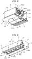
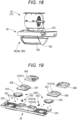
- the drain pan 40 that receives drain water generated in the heat exchanger 20 is provided at the lower end of the heat exchanger 20.
- the drain pan 40 is integrally formed with a heat insulating member 41 made of styrene foam and a drain sheet 42 made of resin provided on the surface facing the heat exchanger 20.
- the drain pan 40 is formed in a rectangular shape having a size that covers the opening surface on the lower end side of the heat exchanger 20, and is also a partition plate that separates the air blowing chamber F from the air guide path L described later.
- the drain pan 40 is provided with ventilation holes 43 into which the cylindrical blower 343 of the fan unit 30 is fitted, as many as the blowing fans 31 (4 holes in this embodiment).
- the heat exchanger 20 has the front heat exchange part 20L and the rear heat exchange part 20R disposed in a V shape, and the bottom surface is narrower than the upper surface, so that the drain pan 40 becomes smaller by that amount.
- the area occupied by the drain pan 40 in the main unit 10 becomes small, the ventilation resistance due to the drain pan 40 also decreases, and the ventilation area around the drain pan 40 expands to improve ventilation efficiency.
- a gutter 45 is provided to receive the drain water generated in the heat exchanger 20. Further, since the dew condensation water generated on the outer surface side of the fan casing 34 during the cooling operation is received by the drain pan 40, it is preferable to perform waterproof treatment around the ventilation holes 43.
- the drain pan 40 may be provided with a drain pump or a drain hose for draining drain water, a float switch for controlling on/off of the drain pump, and the like.
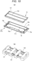
- the configuration of the decorative panel 70 will be described with reference to Figs. 11 to 13 .
- the decorative panel 70 includes the air blowing part 74 on a side of the long side 70a and the air suction part 73 on a side of the other long side 70b.
- a part of the panel portion 71 is formed as a raised portion 740 that is raised in a trapezoidal cross-section shape toward the air conditioning room R along the long side 70a.
- the raised portion 740 has an elliptical shape that is a rounded rectangular shape made up of two parallel lines of equal length and two semicircles, and has the side surface (circumferential surface) having an inclined surface.
- the air blowing part 74 has a fixed air blowing portion 75 in the central portion of the raised portion 740, and movable air blowing portions 77L and 77R on both left and right sides. When it is not necessary to distinguish the movable air blowing portions 77L and 77R, they are collectively referred to as the movable air blowing portion 77.
- the movable air blowing portion 77L includes a truncated cone-shaped rotation unit 78L which rotates within a predetermined angle range around an axial line orthogonal to a virtual plane on the rear surface 70R side of the decorative panel 70 parallel to the bottom surface 101 of the main unit 10.
- the movable air blowing portion 77R also includes a truncated cone-shaped rotation unit 78R which rotates within a predetermined angle range around an axial line orthogonal to a virtual plane on the rear surface 70R side of the decorative panel 70 parallel to the bottom surface 101 of the main unit 10.
- the virtual plane on the rear surface 70R side of the decorative panel 70 is also parallel to the ceiling surface T1 of the air conditioning room R.
- Rotation unit 78 Semi-circular portions are formed at both ends of the raised portion 740 by a part of the rotation units 78L and 78R. When it is not necessary to distinguish between the rotation units 78L and 78R, they are collectively referred to as the rotation unit 78.
- the top surface (bottom surface) 751 of the fixed air blowing portion 75 and the top surface (bottom surface) 781 of the rotation unit 78 are always on the same plane even when the rotation unit 78 is rotated. Therefore, the design is improved.
- the fixed air blowing portion 75 has a trapezoidal cross section, and a first air blowing opening 754 is opened toward the long side 70a of the side surface on the front long side (specific side) 70a side.
- a left/right airflow direction vane 752 (see Fig. 15 ) is provided inside the first air blowing opening 754, and an up/down airflow direction vane 753 is provided on the opening surface of the first air blowing opening 754.
- the movable air blowing portion 77 has a second air blowing opening 783 in a part of the side surface of the rotation unit 78, and the second air blowing opening 783 is provided with an up/down airflow direction vane 782. Since the left and right airflow directions can be changed by the rotation of the rotation unit 78, the movable air blowing portion 77 does not need a left/right airflow direction vane.
- the first air blowing opening 754 of the fixed air blowing portion 75 and the second air blowing opening 783 of the movable air blowing portion 77 are opened along side surfaces having the same inclination angle in order to give these air blowing openings 754 and 783 a unified design.
- the movable air blowing portion 77 rotates between a first position where the second air blowing opening 783 faces the long side 70a and a second position facing the short sides 70c and 70d, and blows out conditioned air, which is sent from the blowing fan 31 within the rotation range, in a predetermined direction.
- the first air blowing opening 754 and the second air blowing opening 783 are disposed linearly.
- This dummy flap 791 is also disposed on the same inclined surface as the first air blowing opening 754 and the second air blowing opening 783.
- Figs. 12 and 13 illustrate a state in which the left movable air blowing portion 77L is at the first position and the right movable air blowing portion 77R is at the second position facing the short side 70d.
- the indoor unit 1 is an omnidirectional (multidirectional) blowout type capable of blowing out conditioned air in all directions except the direction of the rear long side 70b.
- the first air blowing opening 754 of the fixed air blowing portion 75 and the second air blowing opening 783 of the movable air blowing portion 77 are formed on the side surfaces of the raised portion 740 which is formed by projecting a part of the panel portion 71 in a trapezoidal cross-section shape toward the air conditioning room R. Therefore, the conditioned air is blown out substantially horizontally from the first air blowing opening 754 and the second air blowing opening 783 along the panel surface 70S of the decorative panel 70, so that the conditioned air can be spread farther.
- the conditioned air is simultaneously blown out from the first air blowing opening 754 and the second air blowing opening 783, but it is difficult to make a boundary between the air flow blown out from the first air blowing opening 754 and the air flow blown out from the second air blowing opening 783, and the air conditioning room R can be uniformly conditioned.
- the first air blowing opening 754 and the second air blowing opening 783 may be opened in a vertical plane orthogonal to the panel surface (or ceiling surface) of the decorative panel 70.
- the fixed air blowing portion 75 and the left and right movable air blowing portions 77 are housed in the elliptical raised portion 740.
- the movable air blowing portion 77 can rotate about the axial line orthogonal to the virtual plane on the rear surface 70R side of the decorative panel 70 parallel to the bottom surface 101 of the main unit 10, the movable air blowing portions 77 may be simply disposed on both sides of the fixed air blowing portion 75 without being restricted by the appearance, and such aspects are also included in the invention.
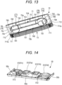
- the partition plate unit 50 illustrated in Fig. 14 is attached to the rear surface 70R side of the decorative panel 70.
- the partition plate unit 50 includes four ducts 51 (51a to 51d) on the upper surface side (the surface facing the drain pan 40), which are respectively fitted to four ventilation holes 43 (43a to 43d; see Fig. 9 ) formed in the drain pan 40 to communicate with the blower 343 of the fan unit 30.
- the ventilation holes 43 are quadrangular holes
- the ducts 51 (51a to 51d) fitted into the ventilation holes 43 are quadrangular tubular shapes (square tubular shapes). These ducts 51 (51a to 51d) extend to the rear surface 70R of the decorative panel 70 as a rectangular tube shape.
- the inner two ducts 51a and 51b are fitted into the corresponding ventilation holes 43a and 43b respectively, and the two ducts 51c and 51d disposed outside are fitted into the corresponding ventilation holes 43a and 43b respectively.
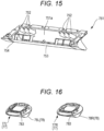
- the ducts 51a and 51b are ducts for the fixed air blowing portion 75, and as illustrated in Fig. 15 , a central air blowing unit 751 having one chamber 751a allocated across the ducts 51a and 51b is attached on the lower surface side of the partition plate unit 50.
- the left/right airflow direction vane 752 is provided in the chamber 751a. Further, the first air blowing opening 754 is formed on the front surface side of the central air blowing unit 751, and the up/down airflow direction vane 753 is provided therein.
- a motor for driving the left/right airflow direction vane 752 is disposed on the back surface of the chamber 751a, and a motor for driving the up/down airflow direction vane 754 is disposed beside the first air blowing opening 754.
- the outer ducts 51c and 51d are ducts for the movable air blowing portion 77, and as illustrated in Fig. 16 , the rotation unit 78L of the left movable air blowing portion 77L is rotatably attached to the lower end of the left duct 51c.
- the rotation unit 78R of the right movable air blowing portion 77R is rotatably attached to the lower end of the right duct 51d.
- Both the rotation units 78L and 78R are driven by a motor.
- the motor that drives the rotation unit 78 is disposed in a motor cover 512 illustrated beside the outer ducts 51c and 51d in Fig. 14 .
- the rotation units 78L and 78R are respectively rotatable from the first position to the position of 90° or more, for example, 100° as the second position.
- a short circuit phenomenon may occur in which the blown air is sucked into the air suction part 73 without going to the air conditioning room R.
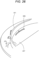
- a wall 711 is provided between the rotation unit 78 and the air suction part 73.
- the wall 711 is formed in a slope shape in which a part of the panel portion 71 around the rotation unit 78 rises up from the short sides 70c and 70d to the height of the top surface 781 of the rotation unit 78 or the height of the air suction part 73 to face between the rotation units 78L and 78R and the air suction part 73.
- a ridge 711a of the wall 711 has a slope shape.
- the short circuit phenomenon when the rotation unit 78 is rotated to the vicinity of the maximum rotation position by the wall 711 is prevented, and the blown air flow reaches farther along a slope surface 712 of the wall 711. That is, the wall 711 not only prevents the short circuit phenomenon, but also functions as an airflow guide surface that allows the blown air to reach farther by providing the slope surface 712.
- the remaining panel surface 70S except for the air suction part 73 of the decorative panel 70 acts as an airflow guide surface including the slope surface 712 of the wall 711.
- the decorative panel 70 is attached to the main unit 10 by fitting the side wall 72 into the bottom surface opening of the main unit 10 and screwing.
- the air suction part 73 is disposed on the first air suction chamber S1 side, and at the time of assembly, as illustrated by the arrow in Fig. 6 , the air guide path L is formed between a bottom surface 40R of the drain pan 40 (see Figs. 3 and 9 ) and the rear surface 70R of the decorative panel 70 to guide a part of the air sucked from the air suction part 73 to the second air suction chamber S2.
- a recess 46 that enlarges the cross-sectional area of the ventilation path L is formed on the bottom surface 40R of the drain pan 40 corresponding to between the ducts 51 and 51.
- the decorative panel 70 is provided with the raised portion 740 including the fixed air blowing portion 75 and the movable air blowing portion 77, and the air guide path L having a larger vertical width can be secured between the drain pan 40 and the decorative panel 70 by forming the first air blowing opening 754 of the fixed air blowing portion 75 and the second air blowing opening 783 of the movable air blowing portion 77 in the side surface of the raised portion 740.
- the air suction part 73 is disposed so as to be included in the panel surface 70S of the decorative panel 70 above the raised portion 740 when viewed from the inside of the air conditioning room R. As a result, the air suction part 73 is positioned closer to the air guide path L, and a part of the air sucked from the air suction part 73 is easily moved to the second air suction chamber S2 side through the air guide path L.
- the assembly of the indoor unit 1 will be described.
- the top plate 111 side of the outer trunk 11 is placed on an assembly table, and the heat insulating material 13 is fitted inside the outer trunk 11.
- a gas connecting pipe and a liquid connecting pipe (both not illustrated) of the assembled heat exchanger 20 (the heat exchanger in which the front heat exchange part 20L and the rear heat exchange part 20R are connected by the connecting plate 21) are pulled out from the side plate 113.
- the heat exchanger 20 is fixed to the top plate 111 via a predetermined fixture (not illustrated).
- the assembled fan unit 30 is disposed in the air blowing chamber F in the heat exchanger 20 and fixed to the top plate 111 via the motor mounting base 361 and the fan fixing part 341.
- the gutter 45 on the drain sheet 42 side of the drain pan 40 is fitted to the bottom surface of the outer trunk 11 in alignment with the lower ends of the heat exchange parts 20L and 20R.
- the blower 343 of the fan casing 34 is fitted into the ventilation hole 43 of the drain pan 40.
- the main unit 10 assembled as described above and the decorative panel 70 are individually packaged and transported to the installation site.
- the main unit 10 is installed on the ceiling back space T2 by being suspended by a plurality of hanging bolts embedded in the ceiling back space T2 in advance.
- the decorative panel 70 is attached from the air conditioning room R side.
- the duct 51 of the partition plate unit 50 is connected to the blower 343 of the fan casing 34 via the ventilation hole 43 of the drain pan 40.
- the indoor unit 1 can be operated by connecting a refrigerant pipe, a power supply line, and a signal line to the outdoor unit.
- the rotation units 78L and 78R of the movable air blowing portions 77L and 77R are set to the initial position such that their second air blowing openings 783 are oriented in the same direction (long side 70a) as the first air blowing opening 754 of the fixed air blowing portion 75 (first position), and both the first air blowing opening 754 and the second air blowing opening 783 are closed by the up/down airflow direction vanes 782 and 753.
- the compressor and the fan motor (both not illustrated) of the outdoor unit and the fan motor 36 of the indoor unit 1 start operating in response to a user command from a remote controller (not illustrated) or a command from the air conditioning system.
- the blowing fan 31 rotates by the operation of the fan motor 36. Due to the rotation of the blowing fan 31, the air in the blower 343 of the blowing fan 31 is blown out, so that the inside of the air blowing chamber F becomes a negative pressure, and the air K in the air conditioning room R is sucked from the air suction part 73 provided in the decorative panel 70.
- the air K sucked from the air suction part 73 flows into the first air suction chamber S1 and also flows into the second air suction chamber S2 through the air guide path L.
- the air in the first air suction chamber S1 passes through the rear heat exchange part 20R, is heat-exchanged with the refrigerant, and enters the air blowing chamber F.
- the air in the second air suction chamber S2 passes through the front heat exchange part 20L, is heat-exchanged with the refrigerant, and enters the air blowing chamber F.
- the air thus conditioned is sent out by the rotation of the blowing fan 31 from the blower 343 of the fan casing 34 toward the fixed air blowing portion 75 and the movable air blowing portion 77 of the decorative panel 70 through the duct 51.
- the conditioned air sent to the fixed air blowing portion 75 is blown out from the first air blowing opening 754 in the direction guided by the left/right airflow direction vane 752 and the up/down airflow direction vane 753.
- the conditioned air sent to the movable air blowing portion 77 is blown out in the rotation direction of the rotation unit 78 and the direction guided by the up/down airflow direction vane 782.
- the conditioned air can be supplied in multiple directions except the direction of the long side 70b on the rear side where the air suction part 73 is provided, according to the user's request.
- the indoor unit 1 includes the partition plate unit 50 illustrated in Fig. 14 on the rear surface 70R of the decorative panel 70, as described above.
- the partition plate unit 50 is attached to the air blowing part 74 of the decorative panel 70, but is large and heavy because the fixed air blowing portion 75, the movable air blowing portion 77, and the like are provided.
- the frame 721 described in Figs. 10(a) and 10(b) is provided on the rear surface of the decorative panel 70 for the purpose of preventing damage due to impact such as dropping, but here, as illustrated in Figs. 17(a) and 17(b) , a frame 760 is provided on the rear surface 70R side of the decorative panel 70 to support the partition plate unit 50.
- the frame 760 is a main frame, and includes long side frames 761 and 762 disposed respectively along the long sides 70a and 70b of the decorative panel 70, and short side frames 763 and 764 disposed respectively along the short sides 70c and 70d of the decorative panel 70 between both ends of the long side frames 761 and 762.
- Two beams 765 and 766 are suspended between the short side frame 763 and the short side frame 764.
- the long side frames 761 and 762, the short side frames 763 and 764, and the beams 765 and 766 are preferably made of sheet metal.
- the partition plate unit 50 is attached so that the fixed air blowing portion 75 and the movable air blowing portion 77 project toward the air conditioning room R side such that an opening 74a forming the air blowing part 74 is formed along the long side 70a of the decorative panel 70.
- the beams 765 and 766 are disposed on the long side of the opening 74a in which the air blowing part 74 is provided, respectively, and the partition plate unit 50 is supported by the beams 765 and 766 on the rear surface 70R side of the decorative panel 70.
- the partition plate unit 50 is mounted on the rear surface 70R of the decorative panel 70 in a state of being fitted into the frame 760 such that three edges of a front edge 50a, a right edge 50b, and a left edge 50c are surrounded by the front long side frame 761 and the left and right short side frames 763 and 764. As a result, the beams 765 and 766 are sandwiched between the partition plate unit 50 and the rear surface 70R of the decorative panel 70.
- the partition plate unit 50 can be mounted on the rear surface of the decorative panel 70 without deforming or distorting the decorative panel 70.
- the fan unit 30 and the rotation unit 78 are connected through the partition plate unit 50 so that air can circulate.
- the partition plate unit 50 is provided with the driver 600 for rotating the rotation unit 78.
- the driver 600 is provided in each of the rotation units 78L and 78R, but the configuration is the same.
- the driver 600 includes an annular rotation ring 610 integrally connected to the upper portion of the rotation unit 78, and a motor unit 650 that rotates the rotation ring 610.
- the rotation ring 610 has a cylindrical portion 611, and rack teeth 613 are formed on the outer circumference of the cylindrical portion 611 along the arc surface of the outer circumference.
- the rack teeth 613 may be formed over the entire circumference of the cylindrical portion 611, but may be formed in a range that realizes at least the rotation range of the rotation unit 78 (the range between the first position and the second position described above).
- a flange 614 is formed concentrically on the outer circumference of the cylindrical portion 611 toward the outer side in the radial direction.
- this flange 614 will be referred to as an outer flange.
- a vent hole 612 communicating with the duct 51 (51c, 51d) for the movable air blowing portion is formed in a rectangular shape.
- the motor unit 650 has a motor (preferably a stepping motor) 651 capable of forward and reverse rotation, a pinion gear 652 attached to its output shaft 651a, and a mount 653 for attachment.
- the pinion gear 652 is attached to a predetermined portion of a duct cover 630 described later so as to mesh with the rack teeth 613 of the rotation ring 610.
- circular openings 520 into which the rotation rings 610 are fitted are formed on both sides of the partition plate unit 50.
- a flange 521 is formed concentrically on the inner periphery of the opening 520 toward the inner side in the radial direction.
- this flange 521 is referred to as an inner flange.
- the outer flange 614 When the rotation ring 610 is fitted into the opening 520, the outer flange 614 is disposed on the inner flange 521, and the outer flange 614 slides on the inner flange 521 as the rotation ring 610 rotates.
- the outer flange 614 and the inner flange 521 function as a kind of thrust bearing that receives a load in the axial direction of the rotating body.
- the duct cover 630 is put on to hold the rotation ring 610.
- the duct cover 630 is screwed to the partition plate unit 50.
- the duct cover 630 is formed with the duct 51 (51c, 51d) connected to the ventilation hole 43 formed in the drain pan 40. Further, the duct cover 630 is formed with a pedestal 631 to which the motor unit 650 is attached.
- an annular guide groove 635 into which the cylindrical portion 611 of the rotation ring 610 is fitted is formed on the rear surface 630R of the duct cover 630. Further, the circular portion surrounded by the guide groove 635 on the rear surface 630R of the duct cover 630 becomes an inner bottom surface 633 having a height slightly lower than an edge 630a of the duct cover 630 in Fig. 27 (slightly higher than the edge 630a in the cross-sectional view of Fig. 28 ).
- the duct 51 (51c, 51d) has a rectangular shape, but its ventilation area (cross-sectional area) is gradually expanded from the upper surface of the duct cover 630 toward the inner bottom surface 633, and the apex (corner) is widened on the inner bottom surface 633 so as to be in contact with the annular guide groove 635.
- the rotation ring 610 rotates along the circumscribed circle of the duct 51 on the inner bottom surface 633 side.
- the blowing pressure changes at the rotating portion of the rotation unit 78, but as described above, the rotation ring 610 is rotated along the circumscribed circle of the ducts 51 on the inner bottom surface 633 side, so that the pressure change in the rotation portion of the rotation unit 78 can be reduced since the blowing path is not blocked even partially. Further, the structure of the joint portion (connecting portion) between the rotation ring 610 and the duct 51 can be downsized.
- the rotation ring 610 does not have to be in contact with the four apexes of the duct 51.
- the rotation ring 610 is a large circle that is in contact with two adjacent apexes of the duct 51 on the inner bottom surface 633 side, and can be rotated without reducing the ventilation area of the duct 51 (without blocking a part of the duct).
- the duct cover 630 is further covered with an outer cover 640.
- the outer cover 640 is slightly larger than the duct cover 630, but may be omitted depending on the case.
- the rattling includes the rattling in the horizontal direction (radial direction) and the rattling in the vertical direction (axial direction).
- a stable seat 523 illustrated in Fig. 24 is used.
- the stable seat 523 has a flat seat portion 524 and a side wall 525 that rises substantially vertically from one end of the seat portion 524, and elastically deformable mounting legs 526 which are slotted are provided in the bottom portion of the seat portion 524.
- the side wall 525 has an arc surface 525a formed along the outer peripheral edge 614a of the outer flange 614.
- the stable seats 523 are preferably formed of a low friction resin such as polyacetal (POM), and in this example, as illustrated in Fig. 23 , there are provided the seats at four positions on the outer peripheral side of the inner flange 521 at 90° intervals. As another example, the seats may be provided at three locations at 120° intervals. Further, when the length of the stable seat 523 (the length along the circumferential direction of the inner flange 521) is long, it may be disposed at two positions.
- POM polyacetal
- the stable seat 523 is attached to the inner flange 521 along the outer peripheral edge 614a of the outer flange 614 of the rotation ring 610.
- an engagement hole 522 is provided in the inner flange 521 to be projected, and the mounting legs 526 may be pushed into the engagement hole 522 while elastically deforming.
- a protruding piece 616 is provided inside the cylindrical body 611 of the rotation ring 610.
- the vent hole 612 formed in the cylindrical portion 611 has a rectangular shape, an inner wall 617 forming each side of the rectangular shape exists inside the cylindrical portion 611.
- the protruding piece 616 is erected on the inner wall 617.
- the position of the protruding piece 616 is such that it can abut on the inner bottom surface 633 on the rear surface 630R of the duct cover 630 illustrated in Fig. 27 .
- the inner bottom surface 633 is disposed along three sides of the rectangular opening of the duct 51, and the protruding pieces 616 are provided at 90° intervals at four positions as illustrated in Fig. 21 .
- the contact area of each protruding piece 616 with respect to the inner bottom surface 633 is as small as possible.
- the projecting height of the protruding piece 616 is such that the tip end of the protruding piece 616 abuts on the inner bottom surface 633 when the duct cover 630 is put on the rotation ring 610.
- the rotation ring 610 rotates in the opening 520 of the partition plate unit 50 by the motor 651, but it is necessary to take a measure for preventing air leakage from the gap between the inner flange 521 on the opening 520 side and the outer flange 614 on the rotation ring 610 side, and especially a measure for preventing dew condensation during cooling operation.
- the sealing material 618 is provided on the inner surface of the outer flange 614 (the surface side facing the inner flange 521).
- the sealing material 618 only needs to have appropriate elasticity and heat insulating properties, but since it is rubbed by the inner flange 521 as the rotation ring 610 rotates, a tape or sheet obtained by planting on a tape-shaped or sheet-shaped base material with a low-friction fiber such as a fiber made of polyacetal (often short fiber) is preferably employed.
- the clearance between the inner flange 521 and the outer flange 614 can be substantially 0 to 0.5 mm to prevent air leakage. Further, it is possible to adopt a structure in which dew condensation does not occur. Further, the sliding frictional resistance due to the rotation of the rotation ring 610 can be reduced.
- bosses 619 used when connecting the rotation unit 78 are provided at a plurality of positions.
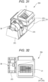
- the blowing fan 31 is fixed to the top plate 111 of the outer trunk 11 via the fan mounting base 311 provided in the fan casing 34, and the fan motor 36 is also fixed to the top plate 111 of the outer trunk 11 via the motor mounting base 361. Therefore, a large number of parts are used, and high positioning accuracy is required for positioning the blowing fan 31 and the fan motor 36.
- Figs. 31 and 32 illustrate a fan unit 30A improved in this respect. Also in this embodiment, a sirocco fan is preferably used as the blowing fan 31, and the fan motor 36 is also used without any change.
- the fan casing 34 of the blowing fan 31 is divided into two parts, a lower casing 371 and an upper casing 372, both made of a synthetic resin material, but a motor mounting base 373 of the fan motor 36 is integrally formed in the lower casing 371.
- a bearing supporting the blowing fan 31 of the lower casing 371 and a bearing supporting the fan motor 36 of the motor mounting base 373 are preliminarily cored when the motor mounting base 373 is integrally molded on the lower casing 371.
- the upper casing 372 may be fixed to the lower casing 371 by a locking tool 374 such as a snap lock.
- the blowing fan 31 and the fan motor 36 are connected in advance, the upper casing 372 is opened, the blowing fan 31 is housed in the lower casing 371, and the fan motor 36 is set on the motor mounting base 373.
- the positions of the blowing fan 31 and the fan motor 36 can be easily adjusted (centered).
- this fan unit 30A is unitized by a minimum unit, it is sufficient to select the number of units to be used according to the amount of blown air required for the air conditioner, the size of the air blowing part, or the like. There is no need to design a dedicated fan unit (air blower) for each of models different in the amount of air. According to this fan unit 30A, since the air volume can be adjusted individually, more detailed air conditioning operation can be performed.
Landscapes
- Engineering & Computer Science (AREA)
- Chemical & Material Sciences (AREA)
- Combustion & Propulsion (AREA)
- Mechanical Engineering (AREA)
- General Engineering & Computer Science (AREA)
- Physics & Mathematics (AREA)
- Thermal Sciences (AREA)
- Air Filters, Heat-Exchange Apparatuses, And Housings Of Air-Conditioning Units (AREA)
Claims (7)
- In eine Raumdecke eingebettete Klimaanlage, welche aufweist:eine kastenförmige Grundeinheit (10), die ein Luftgebläse, einen Wärmetauscher (20) und eine Ablaufwanne (40) umfasst und in einer Decke (T1) eines Klimatisierungsraums (R) anordenbar ist, undeine Dekorblende (70), die an einer Bodenfläche (101) der Grundeinheit (10) entlang einer Deckenfläche des Klimatisierungsraums (R) angebracht ist, wobei die Dekorblende (70) mit einem Luftansaugbereich (73) und einem Luftausblasbereich (74) versehen ist,wobei der Wärmetauscher (20) mindestens zwei Wärmetauscherteile eines vorderen Wärmeaustauschteils (20L) und eines hinteren Wärmeaustauschteils (20R) aufweist, wobei das vordere Wärmeaustauschteil (20L) und das hintere Wärmeaustauschteil (20R) einander zugewandt in der Grundeinheit (10) angeordnet sind,wobei eine Luftausblaskammer (F) zwischen dem vorderen Wärmeaustauschteil (20L) und dem hinteren Wärmeaustauschteil (20R) vorgesehen ist,wobei eine erste Luftansaugkammer (S1) außerhalb des hinteren Wärmetauschteils (20R) vorgesehen ist und eine zweite Luftansaugkammer (S2) außerhalb des vorderen Wärmeaustauschteils (20L) vorgesehen istund wobei der Luftansaugbereich (73) an einer Seite der ersten Luftansaugkammer (S1) angeordnet ist unddas Luftgebläse in der Luftausblaskammer (F) aufgenommen ist, wobei eine Bodenfläche (101) der Luftausblaskammer (F) durch die Ablaufwanne (40) abgeschlossen ist,dadurch gekennzeichnet, dassdie in einer Decke eingebettete Klimaanlage so angeordnet ist, dass ein Luftführungsweg (L) vom Luftansaugbereich (73) zu der zweiten Luftansaugkammer (S2) an einer Seite des vorderen Wärmeaustauschteils (20L) zwischen der Dekorblende (70) und der Ablaufwanne (40) ausgebildet ist.
- In eine Raumdecke eingebettete Klimaanlage nach Anspruch 1,wobei in der Ablaufwanne (40) ein Ventilationsloch (43) ausgebildet ist,wobei in der Dekorblende (70) eine Vielzahl von Kanälen (51, 51a, 51b, 51c, 51d) zu einer Einpassung in das Ventilationsloch (43) vorgesehen ist, um von dem Luftgebläse zum Luftausblasbereich (74) geblasene Luft zu führen,wobei der Luftführungsweg (L) zwischen einem von der Vielzahl von Kanälen (51, 51a, 51b, 51c, 51d) und einem weiteren von der Vielzahl von Kanälen (51, 51a, 51b, 51c, 51d) ausgebildet ist undin einer Bodenfläche (101) der Ablaufwanne (40) eine dem Luftführungsweg (L) entsprechende Ausnehmung (46) ausgebildet ist, um eine Querschnittfläche des Luftführungswegs (L) zu vergrößern.
- In eine Raumdecke eingebettete Klimaanlage nach Anspruch 1 oder 2,
wobei der Luftausblasbereich (74) einen erhabenen Teilbereich (740) aufweist, der über eine Blendenfläche (70S) der Dekorblende (70) in Richtung des klimatisierten Raums (R) herausragt und mit einer Luftausblasöffnung (754, 783) in einer Seitenfläche des erhabenen Teilbereichs (740) ausgebildet ist, um von dem Luftgebläse ausgeblasene Luft entlang der Blendenfläche (70S) der Dekorblende (70) auszublasen. - In eine Raumdecke eingebettete Klimaanlage nach Anspruch 3,
wobei der Luftansaugbereich (73) so angeordnet ist, dass er - von dem Klimatisierungsraum (R) aus gesehen - in der Blendenfläche (70S) der Dekorblende (70) oberhalb des erhabenen Bereichs (740) aufgenommen ist. - In eine Raumdecke eingebettete Klimaanlage nach einem der Ansprüche 1 bis 4,wobei ein Abstand von einer Rotationswelle (35), die eine Mitte des Luftgebläses darstellt, zu dem vorderen Wärmeaustauschteil (20L) L1 beträgt undein Abstand von der Rotationswelle (35), die eine Mitte des Luftgebläses darstellt, zu dem hinteren Wärmeaustauschteil (20R) L2 beträgt undL1 < L2 gegeben ist.
- In eine Raumdecke eingebettete Klimaanlage nach einem der Ansprüche 1 bis 5, wobei das Luftgebläse einen Ventilatormotor (36), ein durch den Ventilatormotor (36) angetriebenes Flügelrad (32) sowie ein das Flügelrad (32) umgebendes Ventilatorgehäuse (34) aufweist
und eine dem vorderen Wärmeaustauschteil (20L) zugewandte Seite des Ventilatorgehäuses (34) in einer horizontalen Ebene ausgebildet ist. - In eine Raumdecke eingebettete Klimaanlage nach einem der Ansprüche 1 bis 6, wobei ein Abstand zwischen einem oberen Ende des vorderen Wärmeaustauschteils (20L) und einem oberen Ende des hinteren Wärmeaustauschteils (20R) größer ist als ein Abstand zwischen einem unteren Ende des vorderen Wärmeaustauschteils (20L) und einem unteren Ende des hinteren Wärmeaustauschteils (20R).
Applications Claiming Priority (4)
| Application Number | Priority Date | Filing Date | Title |
|---|---|---|---|
| JP2018069618A JP6737303B2 (ja) | 2018-03-30 | 2018-03-30 | 天井埋込型空気調和機 |
| JP2018069617A JP6737302B2 (ja) | 2018-03-30 | 2018-03-30 | 天井埋込型空気調和機 |
| JP2018104531A JP6681009B2 (ja) | 2018-05-31 | 2018-05-31 | 天井埋込型空気調和機 |
| PCT/JP2019/010753 WO2019188385A1 (ja) | 2018-03-30 | 2019-03-15 | 天井埋込型空気調和機 |
Publications (3)
| Publication Number | Publication Date |
|---|---|
| EP3779314A1 EP3779314A1 (de) | 2021-02-17 |
| EP3779314A4 EP3779314A4 (de) | 2021-12-22 |
| EP3779314B1 true EP3779314B1 (de) | 2023-12-27 |
Family
ID=68060002
Family Applications (1)
| Application Number | Title | Priority Date | Filing Date |
|---|---|---|---|
| EP19774994.8A Active EP3779314B1 (de) | 2018-03-30 | 2019-03-15 | In eine raumdecke eingebettete klimaanlage |
Country Status (5)
| Country | Link |
|---|---|
| US (1) | US20210025602A1 (de) |
| EP (1) | EP3779314B1 (de) |
| CN (1) | CN111936797B (de) |
| AU (1) | AU2019242468A1 (de) |
| WO (1) | WO2019188385A1 (de) |
Families Citing this family (1)
| Publication number | Priority date | Publication date | Assignee | Title |
|---|---|---|---|---|
| JP6671519B2 (ja) * | 2017-02-09 | 2020-03-25 | 三菱電機株式会社 | 空気調和機の天井埋込型室内機及び空気調和機 |
Family Cites Families (21)
| Publication number | Priority date | Publication date | Assignee | Title |
|---|---|---|---|---|
| JPS5585829A (en) * | 1978-12-20 | 1980-06-28 | Matsushita Electric Ind Co Ltd | Separate type air conditioner |
| JPS62120151U (de) * | 1986-01-22 | 1987-07-30 | ||
| JPH05332568A (ja) * | 1992-05-29 | 1993-12-14 | Hitachi Ltd | 天井埋込型空気調和機 |
| JPH06272884A (ja) * | 1993-03-23 | 1994-09-27 | Mitsubishi Electric Corp | 空気調和機 |
| JP2671865B2 (ja) * | 1995-05-18 | 1997-11-05 | 木村工機株式会社 | カセット形フアンコイルユニット |
| JP3387712B2 (ja) * | 1995-11-27 | 2003-03-17 | 三菱電機株式会社 | 天井埋込型空気調和機の室内ユニット |
| KR19990042027A (ko) * | 1997-11-25 | 1999-06-15 | 구자홍 | 복합형 공기조화기 |
| JP2000213767A (ja) | 1999-01-27 | 2000-08-02 | Matsushita Electric Ind Co Ltd | 空気調和ユニット |
| JP2001263703A (ja) * | 2000-03-21 | 2001-09-26 | Mitsubishi Electric Corp | 天井埋込型空気調和機 |
| JP3596422B2 (ja) * | 2000-04-28 | 2004-12-02 | 松下電器産業株式会社 | 空気調和機の室内ユニット |
| JP4527306B2 (ja) * | 2001-03-16 | 2010-08-18 | 三菱電機株式会社 | 天井埋込形空気調和機 |
| JP3651417B2 (ja) * | 2001-07-18 | 2005-05-25 | ダイキン工業株式会社 | 空気調和機 |
| US7003976B2 (en) * | 2002-12-10 | 2006-02-28 | Lg Electronics Inc. | Air conditioner |
| JP2004245482A (ja) * | 2003-02-13 | 2004-09-02 | Matsushita Electric Ind Co Ltd | 分離型空気調和機 |
| JP2005337571A (ja) * | 2004-05-26 | 2005-12-08 | Daikin Ind Ltd | 高所設置型空気調和機 |
| CN201448947U (zh) * | 2009-07-30 | 2010-05-05 | 广东美的电器股份有限公司 | 分体空调的室内机 |
| JP5267539B2 (ja) * | 2010-11-05 | 2013-08-21 | ダイキン工業株式会社 | 床置き室内機 |
| JP5659121B2 (ja) * | 2011-10-05 | 2015-01-28 | 日立アプライアンス株式会社 | 空気調和機 |
| KR101912634B1 (ko) * | 2012-11-26 | 2018-10-29 | 엘지전자 주식회사 | 공기조화기 |
| JP2018119713A (ja) * | 2017-01-24 | 2018-08-02 | 株式会社富士通ゼネラル | 天井埋込型空気調和機 |
| JP6855875B2 (ja) * | 2017-03-28 | 2021-04-07 | 株式会社富士通ゼネラル | 天井埋込型空気調和機の室内機 |
-
2019
- 2019-03-15 EP EP19774994.8A patent/EP3779314B1/de active Active
- 2019-03-15 CN CN201980022740.6A patent/CN111936797B/zh active Active
- 2019-03-15 WO PCT/JP2019/010753 patent/WO2019188385A1/ja active Application Filing
- 2019-03-15 AU AU2019242468A patent/AU2019242468A1/en active Pending
- 2019-03-15 US US17/042,517 patent/US20210025602A1/en active Pending
Also Published As
| Publication number | Publication date |
|---|---|
| CN111936797B (zh) | 2022-08-02 |
| WO2019188385A1 (ja) | 2019-10-03 |
| AU2019242468A1 (en) | 2020-10-15 |
| US20210025602A1 (en) | 2021-01-28 |
| CN111936797A (zh) | 2020-11-13 |
| EP3779314A1 (de) | 2021-02-17 |
| EP3779314A4 (de) | 2021-12-22 |
Similar Documents
| Publication | Publication Date | Title |
|---|---|---|
| EP3812664B1 (de) | In eine raumdecke eingebettete klimaanlage | |
| EP3779317B1 (de) | In eine raumdecke eingebettete klimaanlage | |
| EP3842705A1 (de) | In eine raumdecke eingebettete klimaanlage | |
| EP3805659A1 (de) | In eine raumdecke eingebettete klimaanlage | |
| EP3779314B1 (de) | In eine raumdecke eingebettete klimaanlage | |
| JP6730688B2 (ja) | 空気調和機 | |
| JP7197826B2 (ja) | 天井埋込型空気調和機 | |
| JP6681009B2 (ja) | 天井埋込型空気調和機 | |
| JP7161668B2 (ja) | 天井埋込型空気調和機 | |
| JP7075053B2 (ja) | 天井埋込型空気調和機 | |
| JP7068609B2 (ja) | 天井埋込型空気調和機 | |
| JP7070831B2 (ja) | 天井埋込型空気調和機 | |
| JP2019211102A (ja) | 天井埋込型空気調和機 | |
| EP3779315B1 (de) | In eine raumdecke eingebettete klimaanlage | |
| JP2019211101A (ja) | 天井埋込型空気調和機 | |
| EP3779313A1 (de) | In eine raumdecke eingebettete klimaanlage |
Legal Events
| Date | Code | Title | Description |
|---|---|---|---|
| STAA | Information on the status of an ep patent application or granted ep patent |
Free format text: STATUS: THE INTERNATIONAL PUBLICATION HAS BEEN MADE |
|
| PUAI | Public reference made under article 153(3) epc to a published international application that has entered the european phase |
Free format text: ORIGINAL CODE: 0009012 |
|
| STAA | Information on the status of an ep patent application or granted ep patent |
Free format text: STATUS: REQUEST FOR EXAMINATION WAS MADE |
|
| 17P | Request for examination filed |
Effective date: 20201020 |
|
| AK | Designated contracting states |
Kind code of ref document: A1 Designated state(s): AL AT BE BG CH CY CZ DE DK EE ES FI FR GB GR HR HU IE IS IT LI LT LU LV MC MK MT NL NO PL PT RO RS SE SI SK SM TR |
|
| AX | Request for extension of the european patent |
Extension state: BA ME |
|
| DAV | Request for validation of the european patent (deleted) | ||
| DAX | Request for extension of the european patent (deleted) | ||
| A4 | Supplementary search report drawn up and despatched |
Effective date: 20211119 |
|
| RIC1 | Information provided on ipc code assigned before grant |
Ipc: F24F 13/22 20060101ALI20211115BHEP Ipc: F24F 13/065 20060101ALI20211115BHEP Ipc: F24F 1/0063 20190101ALI20211115BHEP Ipc: F24F 1/0047 20190101ALI20211115BHEP Ipc: F24F 1/0014 20190101ALI20211115BHEP Ipc: F24F 13/20 20060101AFI20211115BHEP |
|
| GRAP | Despatch of communication of intention to grant a patent |
Free format text: ORIGINAL CODE: EPIDOSNIGR1 |
|
| STAA | Information on the status of an ep patent application or granted ep patent |
Free format text: STATUS: GRANT OF PATENT IS INTENDED |
|
| INTG | Intention to grant announced |
Effective date: 20230718 |
|
| GRAS | Grant fee paid |
Free format text: ORIGINAL CODE: EPIDOSNIGR3 |
|
| GRAA | (expected) grant |
Free format text: ORIGINAL CODE: 0009210 |
|
| STAA | Information on the status of an ep patent application or granted ep patent |
Free format text: STATUS: THE PATENT HAS BEEN GRANTED |
|
| AK | Designated contracting states |
Kind code of ref document: B1 Designated state(s): AL AT BE BG CH CY CZ DE DK EE ES FI FR GB GR HR HU IE IS IT LI LT LU LV MC MK MT NL NO PL PT RO RS SE SI SK SM TR |
|
| REG | Reference to a national code |
Ref country code: GB Ref legal event code: FG4D |
|
| REG | Reference to a national code |
Ref country code: CH Ref legal event code: EP |
|
| REG | Reference to a national code |
Ref country code: DE Ref legal event code: R096 Ref document number: 602019044075 Country of ref document: DE |
|
| REG | Reference to a national code |
Ref country code: IE Ref legal event code: FG4D |
|
| PG25 | Lapsed in a contracting state [announced via postgrant information from national office to epo] |
Ref country code: GR Free format text: LAPSE BECAUSE OF FAILURE TO SUBMIT A TRANSLATION OF THE DESCRIPTION OR TO PAY THE FEE WITHIN THE PRESCRIBED TIME-LIMIT Effective date: 20240328 |
|
| REG | Reference to a national code |
Ref country code: LT Ref legal event code: MG9D |
|
| PG25 | Lapsed in a contracting state [announced via postgrant information from national office to epo] |
Ref country code: LT Free format text: LAPSE BECAUSE OF FAILURE TO SUBMIT A TRANSLATION OF THE DESCRIPTION OR TO PAY THE FEE WITHIN THE PRESCRIBED TIME-LIMIT Effective date: 20231227 |
|
| PG25 | Lapsed in a contracting state [announced via postgrant information from national office to epo] |
Ref country code: LT Free format text: LAPSE BECAUSE OF FAILURE TO SUBMIT A TRANSLATION OF THE DESCRIPTION OR TO PAY THE FEE WITHIN THE PRESCRIBED TIME-LIMIT Effective date: 20231227 Ref country code: GR Free format text: LAPSE BECAUSE OF FAILURE TO SUBMIT A TRANSLATION OF THE DESCRIPTION OR TO PAY THE FEE WITHIN THE PRESCRIBED TIME-LIMIT Effective date: 20240328 Ref country code: FI Free format text: LAPSE BECAUSE OF FAILURE TO SUBMIT A TRANSLATION OF THE DESCRIPTION OR TO PAY THE FEE WITHIN THE PRESCRIBED TIME-LIMIT Effective date: 20231227 Ref country code: BG Free format text: LAPSE BECAUSE OF FAILURE TO SUBMIT A TRANSLATION OF THE DESCRIPTION OR TO PAY THE FEE WITHIN THE PRESCRIBED TIME-LIMIT Effective date: 20240327 |
|
| PGFP | Annual fee paid to national office [announced via postgrant information from national office to epo] |
Ref country code: DE Payment date: 20240220 Year of fee payment: 6 Ref country code: GB Payment date: 20240222 Year of fee payment: 6 |
|
| REG | Reference to a national code |
Ref country code: NL Ref legal event code: MP Effective date: 20231227 |
|
| REG | Reference to a national code |
Ref country code: AT Ref legal event code: MK05 Ref document number: 1644865 Country of ref document: AT Kind code of ref document: T Effective date: 20231227 |
|
| PG25 | Lapsed in a contracting state [announced via postgrant information from national office to epo] |
Ref country code: NL Free format text: LAPSE BECAUSE OF FAILURE TO SUBMIT A TRANSLATION OF THE DESCRIPTION OR TO PAY THE FEE WITHIN THE PRESCRIBED TIME-LIMIT Effective date: 20231227 |