EP3775397B1 - Machine de travail, accessoire de travail et combinaison de ceux-ci - Google Patents
Machine de travail, accessoire de travail et combinaison de ceux-ci Download PDFInfo
- Publication number
- EP3775397B1 EP3775397B1 EP18717219.2A EP18717219A EP3775397B1 EP 3775397 B1 EP3775397 B1 EP 3775397B1 EP 18717219 A EP18717219 A EP 18717219A EP 3775397 B1 EP3775397 B1 EP 3775397B1
- Authority
- EP
- European Patent Office
- Prior art keywords
- work attachment
- construction machine
- electric
- work
- power circuit
- Prior art date
- Legal status (The legal status is an assumption and is not a legal conclusion. Google has not performed a legal analysis and makes no representation as to the accuracy of the status listed.)
- Active
Links
Images

Classifications
-
- E—FIXED CONSTRUCTIONS
- E02—HYDRAULIC ENGINEERING; FOUNDATIONS; SOIL SHIFTING
- E02F—DREDGING; SOIL-SHIFTING
- E02F9/00—Component parts of dredgers or soil-shifting machines, not restricted to one of the kinds covered by groups E02F3/00 - E02F7/00
- E02F9/20—Drives; Control devices
- E02F9/2058—Electric or electro-mechanical or mechanical control devices of vehicle sub-units
- E02F9/2095—Control of electric, electro-mechanical or mechanical equipment not otherwise provided for, e.g. ventilators, electro-driven fans
-
- B—PERFORMING OPERATIONS; TRANSPORTING
- B60—VEHICLES IN GENERAL
- B60L—PROPULSION OF ELECTRICALLY-PROPELLED VEHICLES; SUPPLYING ELECTRIC POWER FOR AUXILIARY EQUIPMENT OF ELECTRICALLY-PROPELLED VEHICLES; ELECTRODYNAMIC BRAKE SYSTEMS FOR VEHICLES IN GENERAL; MAGNETIC SUSPENSION OR LEVITATION FOR VEHICLES; MONITORING OPERATING VARIABLES OF ELECTRICALLY-PROPELLED VEHICLES; ELECTRIC SAFETY DEVICES FOR ELECTRICALLY-PROPELLED VEHICLES
- B60L1/00—Supplying electric power to auxiliary equipment of vehicles
- B60L1/003—Supplying electric power to auxiliary equipment of vehicles to auxiliary motors, e.g. for pumps, compressors
-
- B—PERFORMING OPERATIONS; TRANSPORTING
- B60—VEHICLES IN GENERAL
- B60L—PROPULSION OF ELECTRICALLY-PROPELLED VEHICLES; SUPPLYING ELECTRIC POWER FOR AUXILIARY EQUIPMENT OF ELECTRICALLY-PROPELLED VEHICLES; ELECTRODYNAMIC BRAKE SYSTEMS FOR VEHICLES IN GENERAL; MAGNETIC SUSPENSION OR LEVITATION FOR VEHICLES; MONITORING OPERATING VARIABLES OF ELECTRICALLY-PROPELLED VEHICLES; ELECTRIC SAFETY DEVICES FOR ELECTRICALLY-PROPELLED VEHICLES
- B60L50/00—Electric propulsion with power supplied within the vehicle
- B60L50/50—Electric propulsion with power supplied within the vehicle using propulsion power supplied by batteries or fuel cells
- B60L50/60—Electric propulsion with power supplied within the vehicle using propulsion power supplied by batteries or fuel cells using power supplied by batteries
-
- E—FIXED CONSTRUCTIONS
- E02—HYDRAULIC ENGINEERING; FOUNDATIONS; SOIL SHIFTING
- E02F—DREDGING; SOIL-SHIFTING
- E02F3/00—Dredgers; Soil-shifting machines
- E02F3/04—Dredgers; Soil-shifting machines mechanically-driven
- E02F3/28—Dredgers; Soil-shifting machines mechanically-driven with digging tools mounted on a dipper- or bucket-arm, i.e. there is either one arm or a pair of arms, e.g. dippers, buckets
- E02F3/36—Component parts
- E02F3/3604—Devices to connect tools to arms, booms or the like
- E02F3/3609—Devices to connect tools to arms, booms or the like of the quick acting type, e.g. controlled from the operator seat
- E02F3/3654—Devices to connect tools to arms, booms or the like of the quick acting type, e.g. controlled from the operator seat with energy coupler, e.g. coupler for hydraulic or electric lines, to provide energy to drive(s) mounted on the tool
-
- E—FIXED CONSTRUCTIONS
- E02—HYDRAULIC ENGINEERING; FOUNDATIONS; SOIL SHIFTING
- E02F—DREDGING; SOIL-SHIFTING
- E02F3/00—Dredgers; Soil-shifting machines
- E02F3/04—Dredgers; Soil-shifting machines mechanically-driven
- E02F3/96—Dredgers; Soil-shifting machines mechanically-driven with arrangements for alternate or simultaneous use of different digging elements
-
- E—FIXED CONSTRUCTIONS
- E02—HYDRAULIC ENGINEERING; FOUNDATIONS; SOIL SHIFTING
- E02F—DREDGING; SOIL-SHIFTING
- E02F9/00—Component parts of dredgers or soil-shifting machines, not restricted to one of the kinds covered by groups E02F3/00 - E02F7/00
- E02F9/20—Drives; Control devices
- E02F9/2025—Particular purposes of control systems not otherwise provided for
-
- E—FIXED CONSTRUCTIONS
- E02—HYDRAULIC ENGINEERING; FOUNDATIONS; SOIL SHIFTING
- E02F—DREDGING; SOIL-SHIFTING
- E02F9/00—Component parts of dredgers or soil-shifting machines, not restricted to one of the kinds covered by groups E02F3/00 - E02F7/00
- E02F9/20—Drives; Control devices
- E02F9/22—Hydraulic or pneumatic drives
- E02F9/2278—Hydraulic circuits
-
- B—PERFORMING OPERATIONS; TRANSPORTING
- B60—VEHICLES IN GENERAL
- B60L—PROPULSION OF ELECTRICALLY-PROPELLED VEHICLES; SUPPLYING ELECTRIC POWER FOR AUXILIARY EQUIPMENT OF ELECTRICALLY-PROPELLED VEHICLES; ELECTRODYNAMIC BRAKE SYSTEMS FOR VEHICLES IN GENERAL; MAGNETIC SUSPENSION OR LEVITATION FOR VEHICLES; MONITORING OPERATING VARIABLES OF ELECTRICALLY-PROPELLED VEHICLES; ELECTRIC SAFETY DEVICES FOR ELECTRICALLY-PROPELLED VEHICLES
- B60L2200/00—Type of vehicles
- B60L2200/40—Working vehicles
-
- B—PERFORMING OPERATIONS; TRANSPORTING
- B60—VEHICLES IN GENERAL
- B60L—PROPULSION OF ELECTRICALLY-PROPELLED VEHICLES; SUPPLYING ELECTRIC POWER FOR AUXILIARY EQUIPMENT OF ELECTRICALLY-PROPELLED VEHICLES; ELECTRODYNAMIC BRAKE SYSTEMS FOR VEHICLES IN GENERAL; MAGNETIC SUSPENSION OR LEVITATION FOR VEHICLES; MONITORING OPERATING VARIABLES OF ELECTRICALLY-PROPELLED VEHICLES; ELECTRIC SAFETY DEVICES FOR ELECTRICALLY-PROPELLED VEHICLES
- B60L2210/00—Converter types
- B60L2210/10—DC to DC converters
-
- B—PERFORMING OPERATIONS; TRANSPORTING
- B60—VEHICLES IN GENERAL
- B60L—PROPULSION OF ELECTRICALLY-PROPELLED VEHICLES; SUPPLYING ELECTRIC POWER FOR AUXILIARY EQUIPMENT OF ELECTRICALLY-PROPELLED VEHICLES; ELECTRODYNAMIC BRAKE SYSTEMS FOR VEHICLES IN GENERAL; MAGNETIC SUSPENSION OR LEVITATION FOR VEHICLES; MONITORING OPERATING VARIABLES OF ELECTRICALLY-PROPELLED VEHICLES; ELECTRIC SAFETY DEVICES FOR ELECTRICALLY-PROPELLED VEHICLES
- B60L2210/00—Converter types
- B60L2210/40—DC to AC converters
-
- B—PERFORMING OPERATIONS; TRANSPORTING
- B60—VEHICLES IN GENERAL
- B60L—PROPULSION OF ELECTRICALLY-PROPELLED VEHICLES; SUPPLYING ELECTRIC POWER FOR AUXILIARY EQUIPMENT OF ELECTRICALLY-PROPELLED VEHICLES; ELECTRODYNAMIC BRAKE SYSTEMS FOR VEHICLES IN GENERAL; MAGNETIC SUSPENSION OR LEVITATION FOR VEHICLES; MONITORING OPERATING VARIABLES OF ELECTRICALLY-PROPELLED VEHICLES; ELECTRIC SAFETY DEVICES FOR ELECTRICALLY-PROPELLED VEHICLES
- B60L53/00—Methods of charging batteries, specially adapted for electric vehicles; Charging stations or on-board charging equipment therefor; Exchange of energy storage elements in electric vehicles
- B60L53/10—Methods of charging batteries, specially adapted for electric vehicles; Charging stations or on-board charging equipment therefor; Exchange of energy storage elements in electric vehicles characterised by the energy transfer between the charging station and the vehicle
- B60L53/14—Conductive energy transfer
- B60L53/16—Connectors, e.g. plugs or sockets, specially adapted for charging electric vehicles
-
- E—FIXED CONSTRUCTIONS
- E01—CONSTRUCTION OF ROADS, RAILWAYS, OR BRIDGES
- E01H—STREET CLEANING; CLEANING OF PERMANENT WAYS; CLEANING BEACHES; DISPERSING OR PREVENTING FOG IN GENERAL CLEANING STREET OR RAILWAY FURNITURE OR TUNNEL WALLS
- E01H1/00—Removing undesirable matter from roads or like surfaces, with or without moistening of the surface
- E01H1/02—Brushing apparatus, e.g. with auxiliary instruments for mechanically loosening dirt
- E01H1/05—Brushing apparatus, e.g. with auxiliary instruments for mechanically loosening dirt with driven brushes
- E01H1/056—Brushing apparatus, e.g. with auxiliary instruments for mechanically loosening dirt with driven brushes having horizontal axes
-
- E—FIXED CONSTRUCTIONS
- E01—CONSTRUCTION OF ROADS, RAILWAYS, OR BRIDGES
- E01H—STREET CLEANING; CLEANING OF PERMANENT WAYS; CLEANING BEACHES; DISPERSING OR PREVENTING FOG IN GENERAL CLEANING STREET OR RAILWAY FURNITURE OR TUNNEL WALLS
- E01H5/00—Removing snow or ice from roads or like surfaces; Grading or roughening snow or ice
- E01H5/04—Apparatus propelled by animal or engine power; Apparatus propelled by hand with driven dislodging or conveying levelling elements, conveying pneumatically for the dislodged material
- E01H5/08—Apparatus propelled by animal or engine power; Apparatus propelled by hand with driven dislodging or conveying levelling elements, conveying pneumatically for the dislodged material dislodging essentially by driven elements
-
- E—FIXED CONSTRUCTIONS
- E02—HYDRAULIC ENGINEERING; FOUNDATIONS; SOIL SHIFTING
- E02F—DREDGING; SOIL-SHIFTING
- E02F3/00—Dredgers; Soil-shifting machines
- E02F3/04—Dredgers; Soil-shifting machines mechanically-driven
- E02F3/28—Dredgers; Soil-shifting machines mechanically-driven with digging tools mounted on a dipper- or bucket-arm, i.e. there is either one arm or a pair of arms, e.g. dippers, buckets
- E02F3/283—Dredgers; Soil-shifting machines mechanically-driven with digging tools mounted on a dipper- or bucket-arm, i.e. there is either one arm or a pair of arms, e.g. dippers, buckets with a single arm pivoted directly on the chassis
-
- E—FIXED CONSTRUCTIONS
- E02—HYDRAULIC ENGINEERING; FOUNDATIONS; SOIL SHIFTING
- E02F—DREDGING; SOIL-SHIFTING
- E02F3/00—Dredgers; Soil-shifting machines
- E02F3/04—Dredgers; Soil-shifting machines mechanically-driven
- E02F3/28—Dredgers; Soil-shifting machines mechanically-driven with digging tools mounted on a dipper- or bucket-arm, i.e. there is either one arm or a pair of arms, e.g. dippers, buckets
- E02F3/36—Component parts
- E02F3/42—Drives for dippers, buckets, dipper-arms or bucket-arms
- E02F3/43—Control of dipper or bucket position; Control of sequence of drive operations
- E02F3/431—Control of dipper or bucket position; Control of sequence of drive operations for bucket-arms, front-end loaders, dumpers or the like
-
- H—ELECTRICITY
- H02—GENERATION; CONVERSION OR DISTRIBUTION OF ELECTRIC POWER
- H02J—CIRCUIT ARRANGEMENTS OR SYSTEMS FOR SUPPLYING OR DISTRIBUTING ELECTRIC POWER; SYSTEMS FOR STORING ELECTRIC ENERGY
- H02J7/00—Circuit arrangements for charging or depolarising batteries or for supplying loads from batteries
- H02J7/0042—Circuit arrangements for charging or depolarising batteries or for supplying loads from batteries characterised by the mechanical construction
- H02J7/0045—Circuit arrangements for charging or depolarising batteries or for supplying loads from batteries characterised by the mechanical construction concerning the insertion or the connection of the batteries
-
- H—ELECTRICITY
- H02—GENERATION; CONVERSION OR DISTRIBUTION OF ELECTRIC POWER
- H02K—DYNAMO-ELECTRIC MACHINES
- H02K11/00—Structural association of dynamo-electric machines with electric components or with devices for shielding, monitoring or protection
- H02K11/0094—Structural association with other electrical or electronic devices
-
- H—ELECTRICITY
- H02—GENERATION; CONVERSION OR DISTRIBUTION OF ELECTRIC POWER
- H02K—DYNAMO-ELECTRIC MACHINES
- H02K11/00—Structural association of dynamo-electric machines with electric components or with devices for shielding, monitoring or protection
- H02K11/30—Structural association with control circuits or drive circuits
- H02K11/33—Drive circuits, e.g. power electronics
-
- Y—GENERAL TAGGING OF NEW TECHNOLOGICAL DEVELOPMENTS; GENERAL TAGGING OF CROSS-SECTIONAL TECHNOLOGIES SPANNING OVER SEVERAL SECTIONS OF THE IPC; TECHNICAL SUBJECTS COVERED BY FORMER USPC CROSS-REFERENCE ART COLLECTIONS [XRACs] AND DIGESTS
- Y02—TECHNOLOGIES OR APPLICATIONS FOR MITIGATION OR ADAPTATION AGAINST CLIMATE CHANGE
- Y02T—CLIMATE CHANGE MITIGATION TECHNOLOGIES RELATED TO TRANSPORTATION
- Y02T10/00—Road transport of goods or passengers
- Y02T10/60—Other road transportation technologies with climate change mitigation effect
- Y02T10/70—Energy storage systems for electromobility, e.g. batteries
Definitions
- the invention relates to a working machine, such as a loader vehicle, comprising a work attachment connection arrangement configured to operationally connect to the working machine a work attachment provided with a work tool, such as a sweeper/rotary broom, a snow blower or a bucket.
- a work attachment of said type and to a combination of a working machine and a work attachment of the above types, such as shown in US 2002/189435 A1 .
- the invention relates in particular to electrically propelled and operated working machines, suchas disclosed in US 2016/137076 A1 .
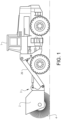
- the invention is applicable to working machines within the fields of industrial construction machines or construction equipment, in particular loader vehicles, wheel loaders etc. Although the invention will be described with respect to an articulated wheel loader, the invention is not restricted to this particular machine, but may also be used for other working machines connectable to work attachments.
- a working vehicle has generally a relatively high power demand and a challenge in electrifying such vehicles is to provide a sufficient battery capacity so that the vehicle can operate during a sufficiently long period of time.
- This is in particular a challenge for a compact loader vehicle (that may not have room for a large battery pack) connected to a work attachment provided with a work tool that requires additional power, such as a sweeper/rotary broom or a snow blower.
- US2002/0189435 discloses an example of a compact loader vehicle provided with a work attachment provided with a rotary broom. Both the loader and the broom are operated by hydraulic means.
- An object of the invention is to provide an electrically operated working machine/loader vehicle, a work attachment and a combination thereof, which devices enable a longer time of operation/working. According to a first aspect of the invention, the object is achieved by a construction machine according to claim 1.
- the electric power circuit of the machine/loader is connectable to an auxiliary or additional battery arranged on the work attachment.
- This allows the auxiliary battery to power the loader, i.e. the electric energy storage capacity can be increased and the time of operation of the working machine can be extended.
- This can be used not only for the application where a certain work tool requires a significantly higher batter capacity, such as a sweeper, but also for e.g. an application where a shovel or bucket is provided with the auxiliary battery so as to provide the working machine with an additional source of electric energy.
- the auxiliary battery can be used for (additional) powering of various electric motors or for powering of a hydraulic pump on the working machine that could be used to drive various hydraulics motor arranged on the attachment or on the working machine.
- Such a design also enables the possibility to control the current between the electric power circuit and each of the first and auxiliary batteries when the work attachment is connected to the working machine, i.e. it can be controlled to what extent each battery should deliver electric energy to the power circuit or to what extent each battery should be supplied with energy from the power circuit (from the other battery or from a charging unit connected to the power circuit).
- this design enables the possibility to use the auxiliary battery for operation and propulsion of the working machine; it is for instance possible to switch off/disconnect a close to uncharged first battery and use the auxiliary battery for propulsion of a vehicle back "home" to a charging unit.
- the first and the auxiliary batteries may be different or of the same type, capacity, voltage etc.; the term “auxiliary” is not used to indicate any particular difference between the batteries but only to give the batteries different names to enhance clarity.
- battery means an electric energy storage device typically comprising a number of electrically connected battery cells.
- the cells may be arranged in groups forming sub-batteries that in turn may be connected in various ways. Cells and sub-batteries may be arranged in what often is called battery pack, which also is an example of an electric energy storage device covered by the term "battery”.
- the battery typically comprises electronic equipment for controlling charging, balancing etc. of the cells and the assembly/assemblies of cells, such as a battery management system (BMS). Batteries, battery packs, electric energy storage devices, BMS etc. are well known as such.
- the work attachment connection arrangement comprises a second electrical connector connected to the electric power circuit of the working machine, wherein the second electrical connector is configured to be connected to a corresponding electrical connector arranged on the work attachment and connected to an electric work tool motor, wherein the electric work tool motor is arranged on the work attachment and configured to directly or indirectly drive the work tool, so as to allow electric connection of the electric work tool motor to the electric power circuit of the working machine when the work attachment is connected to the working machine via the work attachment connection arrangement.
- the electric motor on the work attachment that may be arranged to drive e.g. a rotary broom, can thereby be connected to the electric power circuit of the vehicle and be powered by either or both of the first and auxiliary batteries. This extends the working time considerably for the vehicle compared to the case where a single vehicle battery is used both for powering the vehicle as well as the work tool of the work attachment.
- control system comprises a control unit and a control connection network connecting the control unit with components the control unit is configured to control, wherein the control network comprises a third connector configured to be connected to a corresponding connector arranged on the work attachment and connected to the electric work tool motor so as to allow the control unit to control the electric work tool motor when the work attachment is connected to the working machine via the work attachment connection arrangement.
- the working machine further comprises a first bidirectional DC/DC converter connected to the electric power circuit and to the first rechargeable battery, wherein the first bidirectional DC/DC converter is configured to control a direction and an intensity/magnitude of an electric current that flows between the electric power circuit and the first rechargeable battery.
- this can be used to control whether electric energy (at a certain rate) is to be delivered from the first battery to the power circuit (e.g. during normal operation of the working machine or when a charging unit is connected to the first battery so as to allow charging also of the auxiliary battery via the power circuit), whether electric energy (at a certain rate) is to be supplied from the power circuit to the first battery (e.g. to allow charging of the first battery from a charging unit connected to the power circuit but at another part thereof, e.g. at the auxiliary battery, or to allow charging from an auxiliary battery that is more fully charged than the first battery), or whether the first battery is to be electrically disconnected from the power circuit (e.g. to avoid current leakage when the working machine is not in operation or when it is preferred to use only the auxiliary battery).
- a bidirectional DC/DC converter is capable of internally handling voltage differences so as to direct the current in the desired direction irrespective of the voltage (within reasonable limits) of the two input/output systems or components connected to the converter, i.e. the first battery and the power circuit in this case.
- the voltage of both the first battery and the power circuit is around 48 V.
- the voltage is likely to vary somewhat around 48 V in the two systems/components depending, for instance, on the level of charge of the battery and the current power output in the power circuit. This can be handled by the bidirectional DC/DC converter.
- the working machine further comprises a second bidirectional DC/DC converter connected to the electric power circuit and to the first electric connector, wherein the second bidirectional DC/DC converter is configured to control a direction and an intensity/magnitude of an electric current that flows between the electric power circuit and the first electric connector and thereby to control a direction and an intensity/magnitude of an electric current that flows between the electric power circuit and the auxiliary rechargeable battery when the work attachment is connected to the working machine via the work attachment connection arrangement.
- FIG. 2 shows a schematic view of the electrical connections and components of the work attachment 2 and the loader vehicle 1 according to figure 1 .
- the loader vehicle 1 is provided with a first electric motor 5 arranged for propulsion of the loader vehicle 1 and an additional electric motor 6 arranged to drive a hydraulic pump (not shown) for powering hydraulic systems (not shown), such as steering of the loader vehicle 1 and movement of the lift arms 26.
- the nominal voltage of both the batteries 7, 17 and the electric power circuit 8 is 48 V.
Landscapes
- Engineering & Computer Science (AREA)
- Mechanical Engineering (AREA)
- Mining & Mineral Resources (AREA)
- Civil Engineering (AREA)
- General Engineering & Computer Science (AREA)
- Structural Engineering (AREA)
- Power Engineering (AREA)
- Transportation (AREA)
- Life Sciences & Earth Sciences (AREA)
- Sustainable Development (AREA)
- Sustainable Energy (AREA)
- Operation Control Of Excavators (AREA)
- Harvester Elements (AREA)
Claims (14)
- Engin de chantier (1), tel qu'un véhicule chargeur, ledit engin de chantier comprenant :- un dispositif de raccordement de dispositif de travail (3, 11a, 15a, 16a) configuré pour raccorder opérationnellement à l'engin de chantier (1) un dispositif de travail (2) muni d'un outil de travail (4), tel qu'une balayeuse/un balai rotatif, une souffleuse à neige ou un godet ;- un système de commande (10, 11) configuré pour contrôler le fonctionnement de l'engin de chantier (1) et, lorsque le dispositif de travail (2) est connecté à l'engin de chantier (1) via le dispositif de raccordement du dispositif de travail (3), pour contrôler le fonctionnement du dispositif de travail (2),l'engin de chantier (1) comprend en outre :- au moins un premier moteur électrique (5) configuré pour le fonctionnement de l'engin de chantier (1), le premier moteur électrique étant configuré pour la propulsion de l'engin de chantier- une première batterie rechargeable (7) configurée pour alimenter le premier moteur électrique (5) en énergie électrique ;- un circuit d'alimentation électrique (8) reliant le premier moteur électrique (5) et la première batterie rechargeable (7),caractérisé en ce quele dispositif de raccordement du dispositif de travail (3) comprend un premier connecteur électrique (15a) connecté au circuit d'alimentation électrique (8) de l'engin de chantier (1), dans lequel le premier connecteur électrique (15a) est configuré pour être connecté à un connecteur électrique correspondant (15b) disposé sur le dispositif de travail (2),dans lequel le connecteur électrique correspondant (15b) est connecté à une batterie rechargeable auxiliaire (17) disposée sur le dispositif de travail (2), de manière à permettre la connexion électrique de la batterie rechargeable auxiliaire (17) au circuit d'alimentation électrique (8) de l'engin de chantier (1) pour alimenter l'engin de chantier lorsque le dispositif de travail (2) est connecté à l'engin de chantier (1) via le dispositif de raccordement du dispositif de travail (3).
- Engin de chantier (1) selon la revendication 1, dans lequel le dispositif de raccordement du dispositif de travail (3) comprend un deuxième connecteur électrique (16a) connecté au circuit d'alimentation électrique (8) de l'engin de chantier (1), dans lequel le deuxième connecteur électrique (16a) est configuré pour être connecté à un connecteur électrique correspondant (16b) disposé sur le dispositif de travail (2) et connecté à un moteur électrique d'outil de travail (18), dans lequel le moteur électrique de l'outil de travail (18) est disposé sur le dispositif de travail (2) et configuré pour entraîner directement ou indirectement l'outil de travail (4), de manière à permettre le raccordement électrique du moteur électrique de l'outil de travail (18) au circuit d'alimentation électrique (8) de l'engin de chantier (1) lorsque le dispositif de travail (2) est connecté à l'engin de chantier (1) par l'intermédiaire du dispositif de raccordement du dispositif de travail (3).
- Engin de chantier (1) selon la revendication 2, dans lequel le système de commande comprend une unité de commande (10) et un réseau de connexion de commande (11) reliant l'unité de commande (10) aux composants que l'unité de commande (10) est configurée pour commander, dans lequel le réseau de commande (11) comprend un troisième connecteur (11a) configuré pour être connecté à un connecteur correspondant (11b) disposé sur le dispositif de travail (2) et connecté au moteur électrique de l'outil de travail (18) de manière à permettre à l'unité de commande (10) de contrôler le moteur électrique de l'outil de travail (18) lorsque le dispositif de travail (2) est connecté à l'engin de chantier (1) via le dispositif de raccordement du dispositif de travail (3).
- Engin de chantier (1) selon l'une quelconque des revendications précédentes, dans lequel l'engin de chantier (1) comprend en outre un premier convertisseur CC/CC bidirectionnel (21) connecté au circuit électrique (8) et à la première batterie rechargeable (7), dans lequel le premier convertisseur CC/CC bidirectionnel (21) est configuré pour contrôler une direction et une intensité/magnitude d'un courant électrique qui circule entre le circuit électrique (8) et la première batterie rechargeable (7).
- Engin de chantier (1) selon l'une quelconque des revendications précédentes, dans lequel l'engin de chantier (1) comprend en outre un second convertisseur CC/CC bidirectionnel (22) connecté au circuit d'alimentation électrique (8) et au premier connecteur électrique (15a), dans lequel le second convertisseur CC/CC bidirectionnel (22) est configuré pour contrôler une direction et une intensité/magnitude d'un courant électrique qui circule entre le circuit d'alimentation électrique (8) et le premier connecteur électrique (15a) et donc pour contrôler une direction et une intensité/magnitude d'un courant électrique qui circule entre le circuit d'alimentation électrique (8) et la batterie auxiliaire rechargeable (17) lorsque le dispositif de travail (2) est connecté à l'engin de chantier (1) via le dispositif de raccordement du dispositif de travail (3).
- Engin de chantier (1) selon l'une quelconque des revendications précédentes, dans lequel l'engin de chantier (1) comprend en outre un composant de connexion de charge (23) connecté à la première batterie rechargeable (7), dans lequel le composant de connexion de charge (23) est configuré pour être connecté à une unité de charge de batterie externe.
- Engin de chantier (1) selon l'une quelconque des revendications précédentes, dans lequel l'engin de chantier (1) comprend un moteur électrique supplémentaire (6) conçu pour entraîner une pompe hydraulique pour alimenter les systèmes hydrauliques.
- Dispositif de travail (2) pour un engin de chantier (1), dans lequel le dispositif de travail comprend :- un outil de travail (4), tel qu'une balayeuse/un balai rotatif, une souffleuse à neige ou un godet,le dispositif de travail (2) comprend en outre :- une batterie auxiliaire rechargeable (17),- un connecteur électrique (15b) relié à la batterie auxiliaire rechargeable (17), caractérisé en ce quele connecteur électrique (15b) est configuré pour être connecté à un circuit d'alimentation électrique (8) disposé sur l'engin de chantier (1) de manière à permettre la connexion électrique de la batterie rechargeable auxiliaire (17) au circuit d'alimentation électrique (8) de l'engin de chantier (1) pour alimenter l'engin de chantier lorsque le dispositif de travail (2) est connecté à l'engin de chantier.
- Dispositif de travail (2) selon la revendication 8, dans lequel le dispositif de travail (2) comprend en outre un moteur électrique d'outil de travail (18) configuré pour entraîner directement ou indirectement l'outil de travail (4).
- Dispositif de travail (2) selon la revendication 9, dans lequel le dispositif de travail (2) comprend en outre un second connecteur électrique (16b) connecté au moteur électrique de l'outil de travail (18), dans lequel le second connecteur électrique (16b) est configuré pour être connecté au circuit d'alimentation électrique (8) disposé sur l'engin de chantier (1) de manière à permettre la connexion électrique du moteur électrique de l'outil de travail (18) au circuit d'alimentation électrique (8) de l'engin de chantier (1) lorsque le dispositif de travail (2) est connecté à l'engin de chantier (1).
- Dispositif de travail (2) selon la revendication 9 ou 10, dans lequel une connexion électrique est établie entre la batterie rechargeable auxiliaire (17) et le moteur électrique de l'outil de travail (18) de sorte que la batterie rechargeable auxiliaire (17) puisse fonctionner comme source d'énergie pour le moteur électrique de l'outil de travail (18).
- Dispositif de travail (2) selon l'une quelconque des revendications 8 à 11, dans lequel le dispositif de travail (2) comprend en outre un composant de connexion de charge auxiliaire (24) connecté à la batterie rechargeable auxiliaire (17), dans lequel le composant de connexion de charge auxiliaire (24) est configuré pour être connecté à une unité de charge de batterie externe.
- Dispositif de travail (2) selon l'une quelconque des revendications 8 à 12, dans lequel le dispositif de travail (2) comprend en outre un convertisseur CC/CC bidirectionnel auxiliaire (22) connecté à la batterie rechargeable auxiliaire (17) et au connecteur électrique (15b), dans lequel le convertisseur CC/CC bidirectionnel auxiliaire (22) est configuré pour contrôler une direction et une intensité/magnitude d'un courant électrique qui circule entre la batterie rechargeable auxiliaire (17) et le connecteur électrique (15b) et donc pour contrôler une direction et une intensité/magnitude d'un courant électrique qui circule entre le circuit d'alimentation électrique (8) et la batterie rechargeable auxiliaire (17) lorsque le dispositif de travail (2) est connecté à l'engin de chantier (1).
- Combinaison d'un engin de chantier (1) selon l'une quelconque des revendications 1 à 7 et d'un outil de travail (2) selon la revendication 8, dans laquelle le dispositif de travail (2) est relié à l'engin de chantier (1) par l'intermédiaire du dispositif de raccordement du dispositif de travail (3).
Applications Claiming Priority (1)
| Application Number | Priority Date | Filing Date | Title |
|---|---|---|---|
| PCT/EP2018/025095 WO2019192669A1 (fr) | 2018-04-06 | 2018-04-06 | Machine de travail, accessoire de travail et combinaison de ceux-ci |
Publications (2)
| Publication Number | Publication Date |
|---|---|
| EP3775397A1 EP3775397A1 (fr) | 2021-02-17 |
| EP3775397B1 true EP3775397B1 (fr) | 2025-07-02 |
Family
ID=61965903
Family Applications (1)
| Application Number | Title | Priority Date | Filing Date |
|---|---|---|---|
| EP18717219.2A Active EP3775397B1 (fr) | 2018-04-06 | 2018-04-06 | Machine de travail, accessoire de travail et combinaison de ceux-ci |
Country Status (4)
| Country | Link |
|---|---|
| US (1) | US12252864B2 (fr) |
| EP (1) | EP3775397B1 (fr) |
| CN (1) | CN111684134B (fr) |
| WO (1) | WO2019192669A1 (fr) |
Families Citing this family (14)
| Publication number | Priority date | Publication date | Assignee | Title |
|---|---|---|---|---|
| US20200080277A1 (en) * | 2018-09-10 | 2020-03-12 | Caterpillar Work Tools B.V. | Excavator split connector |
| US11291169B2 (en) * | 2019-10-30 | 2022-04-05 | Billy Gilley | Broom tube assembly |
| WO2021168232A1 (fr) * | 2020-02-19 | 2021-08-26 | Klondike Robotics Corporation | Système de déconstruction de congère |
| DE102020105431A1 (de) * | 2020-03-02 | 2021-09-02 | Weidemann GmbH | Mobile Arbeitsmaschine mit einem elektrischen Arbeitswerkzeug |
| EP4115024A2 (fr) | 2020-03-02 | 2023-01-11 | Clark Equipment Company | Machine à force motrice alimentée électriquement |
| CN112549999A (zh) * | 2020-11-21 | 2021-03-26 | 中联重科股份有限公司 | 供电系统和工程机械 |
| DE102020216269A1 (de) * | 2020-12-18 | 2022-06-23 | Zf Friedrichshafen Ag | Antriebsstrang für eine Arbeitsmaschine, Verfahren zum Betreiben des Antriebsstrangs und Arbeitsmaschine |
| EP4266532A4 (fr) * | 2021-01-29 | 2024-07-03 | Huawei Digital Power Technologies Co., Ltd. | Convertisseur cc/cc bidirectionnel et son procédé de commande, et véhicule |
| WO2023034572A1 (fr) | 2021-09-02 | 2023-03-09 | Clark Equipment Company | Agencements de bras de levage pour machines à moteur |
| CN114086625B (zh) * | 2021-11-05 | 2023-03-24 | 柳州柳工挖掘机有限公司 | 电动挖掘机 |
| EP4177095A1 (fr) | 2021-11-09 | 2023-05-10 | Volvo Construction Equipment AB | Engin de chantier |
| GB2619089A (en) * | 2022-05-27 | 2023-11-29 | Caterpillar Sarl | Work machine system with machine power unit and interchangeable modular units |
| IT202200017166A1 (it) * | 2022-08-11 | 2024-02-11 | Ghedini Ing Fabio & C S A S | Accessorio per macchina operatrice elettrica |
| DE102023202728A1 (de) * | 2023-03-27 | 2024-10-02 | Scheuerle Fahrzeugfabrik Gmbh | Energieversorgungseinheit, System und Schwerlast-Modulfahrzeug |
Family Cites Families (18)
| Publication number | Priority date | Publication date | Assignee | Title |
|---|---|---|---|---|
| US5713419A (en) * | 1996-05-30 | 1998-02-03 | Clark Equipment Company | Intelligent attachment to a power tool |
| DE20012390U1 (de) * | 2000-07-17 | 2000-10-05 | Mieger, Rolf, Ing. (grad.), 88457 Kirchdorf | Hydraulisch schwenkbarer Löffel, insbesondere Grabenräumlöffel |
| US6662881B2 (en) | 2001-06-19 | 2003-12-16 | Sweepster, Llc | Work attachment for loader vehicle having wireless control over work attachment actuator |
| US20030197420A1 (en) | 2002-04-19 | 2003-10-23 | Farmers' Factory Company | Attachment for skid steer loader or other similar work vehicle having local fluid power system |
| JP5319236B2 (ja) * | 2008-10-22 | 2013-10-16 | 日立建機株式会社 | 電源装置および作業機械 |
| US8004242B1 (en) * | 2009-03-13 | 2011-08-23 | PH Ingenuities, LLC | System and method for managing distribution of vehicle power in a multiple battery system |
| JP2011036192A (ja) * | 2009-08-12 | 2011-02-24 | Matsuyama Plow Mfg Co Ltd | 農作業機用リモコン送信装置 |
| US20110114398A1 (en) * | 2009-11-17 | 2011-05-19 | Bianco James S | Battery Power System for Plug In Hybrid Tractor Trailers |
| CN102251545B (zh) * | 2011-04-28 | 2013-12-18 | 上海三一重机有限公司 | 一种电动挖掘机的电气控制系统 |
| US8606448B2 (en) * | 2011-06-29 | 2013-12-10 | Caterpillar Inc. | System and method for managing power in machine having electric and/or hydraulic devices |
| DE102011080633A1 (de) * | 2011-08-09 | 2013-02-14 | Zf Friedrichshafen Ag | Fahrzeug mit einer Antriebsmaschine und einer damit gekoppelten elektrischen Maschine einer Kurbelwellenstartereinrichtung |
| US9251309B2 (en) * | 2011-09-21 | 2016-02-02 | GM Global Technology Operations LLC | Cost-optimized model-based extension of system life |
| US9802493B2 (en) * | 2014-06-20 | 2017-10-31 | Cooper Technologies Company | Multi-phase bidirectional DC to DC power converter circuits, systems and methods with transient stress control |
| US20160137076A1 (en) * | 2014-11-14 | 2016-05-19 | General Electric Company | System, method and apparatus for remote opportunity charging |
| JP6554446B2 (ja) * | 2016-07-27 | 2019-07-31 | 日立建機株式会社 | 電気駆動式作業機械の移動用システム |
| US10173652B2 (en) * | 2016-07-28 | 2019-01-08 | Deere & Company | Hydraulic trailer brake circuit for adjustable gain and improved stability |
| GB2563262B (en) * | 2017-06-08 | 2020-06-10 | Caterpillar Sarl | Improvements in the stability of work machines |
| US10801935B2 (en) * | 2018-01-16 | 2020-10-13 | Deere & Company | System and method for determining a cone index value |
-
2018
- 2018-04-06 EP EP18717219.2A patent/EP3775397B1/fr active Active
- 2018-04-06 CN CN201880088883.2A patent/CN111684134B/zh active Active
- 2018-04-06 US US17/043,409 patent/US12252864B2/en active Active
- 2018-04-06 WO PCT/EP2018/025095 patent/WO2019192669A1/fr not_active Ceased
Also Published As
| Publication number | Publication date |
|---|---|
| CN111684134B (zh) | 2023-05-16 |
| US20210108392A1 (en) | 2021-04-15 |
| EP3775397A1 (fr) | 2021-02-17 |
| CN111684134A (zh) | 2020-09-18 |
| US12252864B2 (en) | 2025-03-18 |
| WO2019192669A1 (fr) | 2019-10-10 |
Similar Documents
| Publication | Publication Date | Title |
|---|---|---|
| EP3775397B1 (fr) | Machine de travail, accessoire de travail et combinaison de ceux-ci | |
| US12291836B2 (en) | Electrically powered construction machine | |
| EP3519237B1 (fr) | Système d'alimentation et procédé pour moteur à courant continu entraînant une pompe hydraulique | |
| EP3006745B1 (fr) | Machine de construction | |
| JP2019190104A (ja) | 電動式作業機械 | |
| US20170291501A1 (en) | Hybrid Construction Machinery | |
| US11993178B2 (en) | Method for operating a drive system for a work machine, drive system and work machine | |
| CN112672918B (zh) | 移动平台系统和方法 | |
| US20220063423A1 (en) | An electric power transmission system for a vehicle | |
| JP5015073B2 (ja) | 充電システム | |
| KR20210122685A (ko) | 이동식 작업기계 | |
| EP2072421A1 (fr) | Système de commande de composants hydrauliques d'une superstructure de véhicule | |
| CN112248792A (zh) | 混合动力系统和工程机械 | |
| KR102074512B1 (ko) | 차량용 전력제어장치 | |
| CN214028233U (zh) | 供电系统和工程车辆 | |
| CN213892155U (zh) | 混合动力系统和工程机械 | |
| JP6966398B2 (ja) | 建設機械 | |
| CN220475453U (zh) | 一种工程机械供电控制系统 | |
| JP5851754B2 (ja) | 作業車両 | |
| CN214879757U (zh) | 电动履带起重机 | |
| EP4638877A1 (fr) | Système d'alimentation électrique hybride à séparation galvanique et procédé de fonctionnement d'un tel système | |
| JP2025140795A (ja) | 作業機械バッテリ暖機制御装置 | |
| CN120731303A (zh) | 作业机械用电动系统以及电动式作业机械 | |
| CN117818380A (zh) | 一种工程机械供电系统及控制方法 | |
| JPH073250U (ja) | バッテリ充電装置 |
Legal Events
| Date | Code | Title | Description |
|---|---|---|---|
| STAA | Information on the status of an ep patent application or granted ep patent |
Free format text: STATUS: UNKNOWN |
|
| STAA | Information on the status of an ep patent application or granted ep patent |
Free format text: STATUS: THE INTERNATIONAL PUBLICATION HAS BEEN MADE |
|
| PUAI | Public reference made under article 153(3) epc to a published international application that has entered the european phase |
Free format text: ORIGINAL CODE: 0009012 |
|
| STAA | Information on the status of an ep patent application or granted ep patent |
Free format text: STATUS: REQUEST FOR EXAMINATION WAS MADE |
|
| 17P | Request for examination filed |
Effective date: 20201106 |
|
| AK | Designated contracting states |
Kind code of ref document: A1 Designated state(s): AL AT BE BG CH CY CZ DE DK EE ES FI FR GB GR HR HU IE IS IT LI LT LU LV MC MK MT NL NO PL PT RO RS SE SI SK SM TR |
|
| AX | Request for extension of the european patent |
Extension state: BA ME |
|
| DAV | Request for validation of the european patent (deleted) | ||
| DAX | Request for extension of the european patent (deleted) | ||
| STAA | Information on the status of an ep patent application or granted ep patent |
Free format text: STATUS: EXAMINATION IS IN PROGRESS |
|
| 17Q | First examination report despatched |
Effective date: 20230525 |
|
| GRAP | Despatch of communication of intention to grant a patent |
Free format text: ORIGINAL CODE: EPIDOSNIGR1 |
|
| STAA | Information on the status of an ep patent application or granted ep patent |
Free format text: STATUS: GRANT OF PATENT IS INTENDED |
|
| INTG | Intention to grant announced |
Effective date: 20250221 |
|
| GRAS | Grant fee paid |
Free format text: ORIGINAL CODE: EPIDOSNIGR3 |
|
| GRAA | (expected) grant |
Free format text: ORIGINAL CODE: 0009210 |
|
| STAA | Information on the status of an ep patent application or granted ep patent |
Free format text: STATUS: THE PATENT HAS BEEN GRANTED |
|
| AK | Designated contracting states |
Kind code of ref document: B1 Designated state(s): AL AT BE BG CH CY CZ DE DK EE ES FI FR GB GR HR HU IE IS IT LI LT LU LV MC MK MT NL NO PL PT RO RS SE SI SK SM TR |
|
| REG | Reference to a national code |
Ref country code: GB Ref legal event code: FG4D |
|
| REG | Reference to a national code |
Ref country code: CH Ref legal event code: EP |
|
| REG | Reference to a national code |
Ref country code: DE Ref legal event code: R096 Ref document number: 602018083164 Country of ref document: DE |
|
| REG | Reference to a national code |
Ref country code: IE Ref legal event code: FG4D |
|
| REG | Reference to a national code |
Ref country code: NL Ref legal event code: MP Effective date: 20250702 |