US20030197420A1 - Attachment for skid steer loader or other similar work vehicle having local fluid power system - Google Patents
Attachment for skid steer loader or other similar work vehicle having local fluid power system Download PDFInfo
- Publication number
- US20030197420A1 US20030197420A1 US10/126,236 US12623602A US2003197420A1 US 20030197420 A1 US20030197420 A1 US 20030197420A1 US 12623602 A US12623602 A US 12623602A US 2003197420 A1 US2003197420 A1 US 2003197420A1
- Authority
- US
- United States
- Prior art keywords
- hydraulic
- electrical
- power
- attachment
- work
- Prior art date
- Legal status (The legal status is an assumption and is not a legal conclusion. Google has not performed a legal analysis and makes no representation as to the accuracy of the status listed.)
- Abandoned
Links
- 239000012530 fluid Substances 0.000 title claims abstract description 51
- 238000010168 coupling process Methods 0.000 claims description 11
- 238000005859 coupling reaction Methods 0.000 claims description 11
- 230000008878 coupling Effects 0.000 claims description 10
- 230000007246 mechanism Effects 0.000 claims description 4
- 239000013589 supplement Substances 0.000 abstract description 2
- 230000004048 modification Effects 0.000 description 4
- 238000012986 modification Methods 0.000 description 4
- 244000007853 Sarothamnus scoparius Species 0.000 description 3
- 239000010720 hydraulic oil Substances 0.000 description 3
- 239000011435 rock Substances 0.000 description 2
- 230000007812 deficiency Effects 0.000 description 1
- -1 dirt Substances 0.000 description 1
- 239000000463 material Substances 0.000 description 1
- 239000004576 sand Substances 0.000 description 1
Images


Classifications
-
- E—FIXED CONSTRUCTIONS
- E02—HYDRAULIC ENGINEERING; FOUNDATIONS; SOIL SHIFTING
- E02F—DREDGING; SOIL-SHIFTING
- E02F3/00—Dredgers; Soil-shifting machines
- E02F3/04—Dredgers; Soil-shifting machines mechanically-driven
- E02F3/96—Dredgers; Soil-shifting machines mechanically-driven with arrangements for alternate or simultaneous use of different digging elements
-
- E—FIXED CONSTRUCTIONS
- E02—HYDRAULIC ENGINEERING; FOUNDATIONS; SOIL SHIFTING
- E02F—DREDGING; SOIL-SHIFTING
- E02F3/00—Dredgers; Soil-shifting machines
- E02F3/04—Dredgers; Soil-shifting machines mechanically-driven
- E02F3/28—Dredgers; Soil-shifting machines mechanically-driven with digging tools mounted on a dipper- or bucket-arm, i.e. there is either one arm or a pair of arms, e.g. dippers, buckets
- E02F3/34—Dredgers; Soil-shifting machines mechanically-driven with digging tools mounted on a dipper- or bucket-arm, i.e. there is either one arm or a pair of arms, e.g. dippers, buckets with bucket-arms, i.e. a pair of arms, e.g. manufacturing processes, form, geometry, material of bucket-arms directly pivoted on the frames of tractors or self-propelled machines
- E02F3/3414—Dredgers; Soil-shifting machines mechanically-driven with digging tools mounted on a dipper- or bucket-arm, i.e. there is either one arm or a pair of arms, e.g. dippers, buckets with bucket-arms, i.e. a pair of arms, e.g. manufacturing processes, form, geometry, material of bucket-arms directly pivoted on the frames of tractors or self-propelled machines the arms being pivoted at the rear of the vehicle chassis, e.g. skid steer loader
-
- E—FIXED CONSTRUCTIONS
- E02—HYDRAULIC ENGINEERING; FOUNDATIONS; SOIL SHIFTING
- E02F—DREDGING; SOIL-SHIFTING
- E02F9/00—Component parts of dredgers or soil-shifting machines, not restricted to one of the kinds covered by groups E02F3/00 - E02F7/00
- E02F9/20—Drives; Control devices
- E02F9/22—Hydraulic or pneumatic drives
Definitions
- the present invention relates generally to attachments for work vehicles, and more particularly relates to fluid power systems for driving actuators on such attachments.
- Skid steer loaders and other work vehicles commonly have a single hydraulic hook-up which comprises a pair of hydraulic quick connect couplings (one for pressurized hydraulic flow and the other for return flow).
- the hydraulic hook-up can be utilized by the attachment for a desired powering purpose.
- a control lever is provided in the operator cab for controlling hydraulic flow to the attachment through the hydraulic couplings.
- One common use of the hydraulic output includes positioning the attachment tool (e.g. shifting the tool left or right about a vertical axis to effect a windrow and/or to direct dirt, gravel or debris, or raising and lowering or tilting the tool).
- the hydraulic output may also be used for hydraulically driving an engaging device such as the rotary rake of a rock raking attachment, a rotary blower of a snowblower or a rotary planner of a cold planner.
- More complex attachments include two or more hydraulic functions or actuators.
- rotary broom attachments, snow-blower attachments, back-hoes, cold planners are some of the attachments that have two or more hydraulic functions or actuators.
- U.S. Pat. No. 5,299,857 to Zanetis, U.S. Pat. No. 5,957,213 to Loraas et al. disclose some of the various types of attachments with multiple hydraulic functions for which the invention can be applicable, and as such these patents are hereby incorporated by reference in their entireties.
- These attachments may include one or more hydraulic cylinders for tilting or rotating the tool about one or more axes; and/or one or more hydraulically driven motors that rotate a tool (e.g. a broom, snow-blower or cold planner).
- the present invention is directed toward a local fluid power system on a attachment for a skid steer loader or other commercial work vehicle.
- the local fluid power system can supplement the existing hydraulic power system provided by the commercial work vehicle or skid steer loader.
- the local fluid power system may comprise a hydraulic reservoir and a hydraulic pump fluidically connected to the hydraulic reservoir for providing a hydraulic power source.
- the local fluid power system may drive a first hydraulic actuator that acts upon the work attachment tool.
- the attachment may include a second actuator that is not driven by the local fluid power system, but instead by the existing hydraulic system provided by the commercial work vehicle.
- FIG. 1 is a schematic of a power machine comprising in combination a skid steer loader and a skid steer attachment having a local fluid power system according to an embodiment of the present invention.
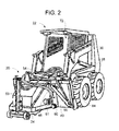
- FIG. 2 is a perspective illustration of a power machine comprising in combination a skid steer loader and a skid steer attachment according to the schematic arrangement shown in FIG. 1.
- FIG. 3 is an isometric drawing of a local fluid power system assembly for mounting to the skid steer attachment shown in FIG. 2.
- FIGS. 1 and 2 an embodiment of the present invention has been illustrated schematically as incorporated in a cold planner attachment 20 to illustrate one application of the present invention.
- the cold planer attachment 20 mounts to a commercial work vehicle shown as a skid steer loader 22 .
- the attachment 20 includes a tool 24 for performing a work operation, in this case grinding pavement.
- the invention is applicable to any one of a variety of attachments such as a back-hoe, a rotary broom, a snow-blower, a tree spade, grapples, or other such similar implements.
- One common element of each of the attachments to which the present invention pertains is that these attachments have one or more fluid powered actuators (typically either hydraulic cylinders or hydraulic rotary motors, although the invention may also be applicable to local pneumatic power systems).
- the skid steer loader 22 includes a conventional hydraulic power system 26 that is driven by the engine of the work vehicle.
- the hydraulic power system 26 supplies hydraulic power to various hydraulic actuators 28 on the skid steer loader 22 , such as those used to raise, lower and tilt the lift arms 30 (see FIG. 2).
- the lift arms 30 typically carry a conventional quick attach plate (not shown) to which the skid steer attachment 20 can quickly mount and dismount.
- the hydraulic power system 26 also includes a hydraulic power output at quick disconnect hydraulic couplings 32 that can attach with quick disconnect hydraulic couplings 34 of the skid steer attachment 20 to supply the skid steer attachment 20 with hydraulic power.
- a control valve 36 is often provided in the work vehicle to reverse or stop flow through the hydraulic lines 38 , 40 .
- the control valve 36 may be a manually operated rocker lever valve or electrically controlled via an operator input device or other suitable valve device.
- the skid steer attachment 20 has a pair of hydraulic hoses 48 , 50 for receiving and returning hydraulic oil to the skid steer loader 22 .
- the hoses 48 , 50 terminate in the quick disconnect couplings 34 to provide for fast attachment and detachment from the hydraulic power system 26 of the skid steer loader 22 .
- the skid steer loader 22 also includes a conventional electrical power supply system 42 which is used to power various electrical functions on the skid steer loader 22 .
- the attachment 20 includes a local hydraulic power system 43 to provide a second source of fluid power separate from the hydraulic power system 26 of the skid steer loader 22 .
- the local hydraulic power system 43 includes a hydraulic reservoir 44 and a hydraulic pump 45 .
- the hydraulic pump 45 is driven by an electrical motor 46 .
- the electrical motor 46 is in turn powered by the electrical power system 42 of the skid steer loader 22 through an electric supply wire 47 running therebetween.
- the attachment 20 includes multiple hydraulic functions.
- FIGS. 1 and 2 illustrate the attachment 20 as having five actuators including one hydraulic rotary motor 51 and four hydraulic cylinders 53 - 56 .
- the hydraulic power system 26 of the skid steer loader 22 is dedicated to driving the rotary motor 51 and therefore rotating the tool 24
- the local hydraulic power system 43 of the attachment 20 is dedicated to positioning the four hydraulic cylinders 53 - 56 .
- the hydraulic oil output of the local hydraulic power system 43 is typically routed to a hydraulic control block 52 where it can be distributed (equally or disproportionately) as desired.
- the control block 52 may include three corresponding control valves 57 - 59 , one for controlling the flow to each different hydraulic cylinder 53 - 56 , respectively (valve 59 controls flow to two cooperating hydraulic cylinders 55 and 56 ).
- the control block 52 centralizes flow, distribution and/or return of hydraulic fluid to the local hydraulic reservoir 44 .
- each valve 57 - 59 has an electrical solenoid control mechanism 61 - 63 (which actually comprises two solenoids for each valve and often return springs to center the valve), respectively, for valve position control.
- Each valve 57 - 59 is also shown as being of the four way, three position type with blocked center. It will be appreciated that the types of valves 57 - 59 and their control may be different depending upon the particular needs of the attachment 20 .
- the valves 57 - 59 may also be of the variable position type with a variable position electrical control device that takes variable positions corresponding to the magnitude of the electrical signal on respective electrical control lines 65 - 67 , respectively.
- each of the valves 57 - 59 are controlled via electrical signals conveyed along electrical wires or control lines 65 - 67 .
- the lines 65 - 67 receive control signals from an operator input device 70 mounted in the cab 72 of the skid steer loader 22 for access by the work vehicle operator.
- the operator input device 70 typically will receive power from the electrical power system 42 of the skid steer loader 22 .
- the electrical wires 65 - 67 are contained within a wire harness 74 that includes a wire coupling 76 interposed thereon to provide for easy coupling and de-coupling when the attachment 20 is attached and detached from the skid steer loader 22 .
- the electric supply wire 47 includes a wire coupling 78 interposed thereon for a similar purpose.
- the local hydraulic power system 43 may preferably includes a check valve 80 to ensure one way flow from the hyraulic pump 45 to the hydraulic control block 52 and a pressure relief valve 82 to relieve excess pressure and/or bypass hydraulic oil to the reservoir 44 when desired.
- the reservoir 44 , the pump 45 , the electrical motor 46 and the hydraulic control block 52 are provided in a compact unit and supported by a common support flange or mount 84 .
- the support flange or mount 84 can be fastened or secured directly to the support frame 86 of the skid steer attachment 22 , the back side of which provides the quick attach plate mechanism for mounting and dismounting to the quick attach plate of the lift arms 30 of the skid steer loader 22 .
- the local fluid power system may be pneumatic and include a compressor that pressurizes a compressed air reservoir.
- compressed air may be used for driving actuators.
- a local hydraulic power system 43 is for hydraulic power boosting.
- most commercial work vehicles are able to supply up to about 3300 psi to work attachments.
- many hydraulic cylinders can be driven at about 5000 psi or more. It certain applications such as rock crushing or other applications requiring large hydraulic power requirements, the relatively moderate hydraulic power supply afforded to the attachment by the work vehicle may not be sufficient.
- the local hydraulic system 43 may thus be used to provide a greater and higher hydraulic power supply to drive hydraulic cylinders for hydraulic functions that need a higher hydraulic power source.
- the local hydraulic power system 43 may be independent of the work vehicle hydraulic system or the local hydraulic system 43 may be provided in series with the hydraulic system of the work vehicle and thereby no local hydraulic reservoir may be needed.
- the local hydraulic system when the local hydraulic system is boosting the power, it may be temporary disconnected either automatically, manually or when determined by appropriate sensors from the hydraulic power system of the vehicle when excess hydraulic power is required to drive a hydraulic actuator.
Landscapes
- Engineering & Computer Science (AREA)
- Mining & Mineral Resources (AREA)
- Civil Engineering (AREA)
- General Engineering & Computer Science (AREA)
- Structural Engineering (AREA)
- Mechanical Engineering (AREA)
- Operation Control Of Excavators (AREA)
Abstract
Description
- The present invention relates generally to attachments for work vehicles, and more particularly relates to fluid power systems for driving actuators on such attachments.
- Commercial work vehicles such as skid steers, loader tractors and other similar heavy equipment vehicles are commonly used for many industrial, agricultural, and landscaping operations. Many of these work vehicles often have two laterally spaced loader arms that extend in front of the vehicle that are adapted to attach to a wide variety of attachments. Commercial work vehicles may also have a three point hitch at their back end. A number of attachments can be selectively attached and detached from the loader arms or the three point hitch to make these work vehicles applicable to a wide variety of applications. For example, a bucket is commonly provided to dig, dump and transport loose materials such as dirt, sand and gravel. The loader arms are hydraulically driven to raise and lower the attachment and pivot the attachment about a horizontal axis.
- Skid steer loaders and other work vehicles commonly have a single hydraulic hook-up which comprises a pair of hydraulic quick connect couplings (one for pressurized hydraulic flow and the other for return flow). The hydraulic hook-up can be utilized by the attachment for a desired powering purpose. A control lever is provided in the operator cab for controlling hydraulic flow to the attachment through the hydraulic couplings. One common use of the hydraulic output includes positioning the attachment tool (e.g. shifting the tool left or right about a vertical axis to effect a windrow and/or to direct dirt, gravel or debris, or raising and lowering or tilting the tool). The hydraulic output may also be used for hydraulically driving an engaging device such as the rotary rake of a rock raking attachment, a rotary blower of a snowblower or a rotary planner of a cold planner.
- More complex attachments include two or more hydraulic functions or actuators. For example rotary broom attachments, snow-blower attachments, back-hoes, cold planners are some of the attachments that have two or more hydraulic functions or actuators. U.S. Pat. No. 5,299,857 to Zanetis, U.S. Pat. No. 5,957,213 to Loraas et al. disclose some of the various types of attachments with multiple hydraulic functions for which the invention can be applicable, and as such these patents are hereby incorporated by reference in their entireties. These attachments may include one or more hydraulic cylinders for tilting or rotating the tool about one or more axes; and/or one or more hydraulically driven motors that rotate a tool (e.g. a broom, snow-blower or cold planner).
- When hydraulically positioning a hydraulically driven rotating tool, hydraulic power is typically diverted away from the main rotary motor of the tool. This can undesirably slow down the rotary speed of the tool. Currently, there is no ideal solution for maintaining a constant full or complete supply of hydraulic power to the main actuator or rotary motor of the tool.
- A further deficiency existing in the art as will be appreciated once the present invention is understood, is the lack of available options with respect to driving fluid actuators on attachments for skid steer loaders or other similar work vehicles.
- In light of the above, it is a general aim of the present invention to provide an alternative way to actuate fluid driven actuators on an attachment for a skid steer loader or other similar work vehicle.
- In accordance with these and other objectives, the present invention is directed toward a local fluid power system on a attachment for a skid steer loader or other commercial work vehicle. The local fluid power system can supplement the existing hydraulic power system provided by the commercial work vehicle or skid steer loader.
- The local fluid power system may comprise a hydraulic reservoir and a hydraulic pump fluidically connected to the hydraulic reservoir for providing a hydraulic power source. The local fluid power system may drive a first hydraulic actuator that acts upon the work attachment tool. The attachment may include a second actuator that is not driven by the local fluid power system, but instead by the existing hydraulic system provided by the commercial work vehicle.
- Other objectives and advantages of the invention will become more apparent from the following detailed description when taken in conjunction with the accompanying drawings.
- The accompanying drawings incorporated in and forming a part of the specification illustrate several aspects of the present invention, and together with the description serve to explain the principles of the invention. In the drawings:
- FIG. 1 is a schematic of a power machine comprising in combination a skid steer loader and a skid steer attachment having a local fluid power system according to an embodiment of the present invention.
- FIG. 2 is a perspective illustration of a power machine comprising in combination a skid steer loader and a skid steer attachment according to the schematic arrangement shown in FIG. 1.
- FIG. 3 is an isometric drawing of a local fluid power system assembly for mounting to the skid steer attachment shown in FIG. 2.
- While the invention will be described in connection with certain preferred embodiments, there is no intent to limit it to those embodiments. On the contrary, the intent is to cover all alternatives, modifications and equivalents as included within the spirit and scope of the invention as defined by the appended claims.
- Referring to FIGS. 1 and 2, an embodiment of the present invention has been illustrated schematically as incorporated in a
cold planner attachment 20 to illustrate one application of the present invention. Thecold planer attachment 20 mounts to a commercial work vehicle shown as askid steer loader 22. Theattachment 20 includes atool 24 for performing a work operation, in this case grinding pavement. However, it will be understood that the invention is applicable to any one of a variety of attachments such as a back-hoe, a rotary broom, a snow-blower, a tree spade, grapples, or other such similar implements. One common element of each of the attachments to which the present invention pertains is that these attachments have one or more fluid powered actuators (typically either hydraulic cylinders or hydraulic rotary motors, although the invention may also be applicable to local pneumatic power systems). - As shown schematically in FIG. 1, the
skid steer loader 22 includes a conventionalhydraulic power system 26 that is driven by the engine of the work vehicle. Thehydraulic power system 26 supplies hydraulic power to varioushydraulic actuators 28 on theskid steer loader 22, such as those used to raise, lower and tilt the lift arms 30 (see FIG. 2). Thelift arms 30 typically carry a conventional quick attach plate (not shown) to which theskid steer attachment 20 can quickly mount and dismount. Thehydraulic power system 26 also includes a hydraulic power output at quick disconnecthydraulic couplings 32 that can attach with quick disconnecthydraulic couplings 34 of theskid steer attachment 20 to supply theskid steer attachment 20 with hydraulic power. Acontrol valve 36 is often provided in the work vehicle to reverse or stop flow through thehydraulic lines control valve 36 may be a manually operated rocker lever valve or electrically controlled via an operator input device or other suitable valve device. Theskid steer attachment 20 has a pair ofhydraulic hoses skid steer loader 22. Thehoses quick disconnect couplings 34 to provide for fast attachment and detachment from thehydraulic power system 26 of theskid steer loader 22. Theskid steer loader 22 also includes a conventional electricalpower supply system 42 which is used to power various electrical functions on theskid steer loader 22. - In accordance with the present invention, the
attachment 20 includes a localhydraulic power system 43 to provide a second source of fluid power separate from thehydraulic power system 26 of theskid steer loader 22. In the disclosed embodiment, the localhydraulic power system 43 includes ahydraulic reservoir 44 and ahydraulic pump 45. Thehydraulic pump 45 is driven by anelectrical motor 46. Theelectrical motor 46 is in turn powered by theelectrical power system 42 of theskid steer loader 22 through anelectric supply wire 47 running therebetween. - The
attachment 20 includes multiple hydraulic functions. FIGS. 1 and 2 illustrate theattachment 20 as having five actuators including one hydraulicrotary motor 51 and four hydraulic cylinders 53-56. In the disclosed embodiment, thehydraulic power system 26 of theskid steer loader 22 is dedicated to driving therotary motor 51 and therefore rotating thetool 24, while the localhydraulic power system 43 of theattachment 20 is dedicated to positioning the four hydraulic cylinders 53-56. - Because there are multiple hydraulic cylinders 53-56, the hydraulic oil output of the local
hydraulic power system 43 is typically routed to ahydraulic control block 52 where it can be distributed (equally or disproportionately) as desired. Thecontrol block 52 may include three corresponding control valves 57-59, one for controlling the flow to each different hydraulic cylinder 53-56, respectively (valve 59 controls flow to two cooperatinghydraulic cylinders 55 and 56). Thecontrol block 52 centralizes flow, distribution and/or return of hydraulic fluid to the localhydraulic reservoir 44. - As shown, each valve 57-59 has an electrical solenoid control mechanism 61-63 (which actually comprises two solenoids for each valve and often return springs to center the valve), respectively, for valve position control. Each valve 57-59 is also shown as being of the four way, three position type with blocked center. It will be appreciated that the types of valves 57-59 and their control may be different depending upon the particular needs of the
attachment 20. The valves 57-59 may also be of the variable position type with a variable position electrical control device that takes variable positions corresponding to the magnitude of the electrical signal on respective electrical control lines 65-67, respectively. - The positions of each of the valves 57-59 are controlled via electrical signals conveyed along electrical wires or control lines 65-67. In FIG. 1, the lines 65-67 receive control signals from an
operator input device 70 mounted in thecab 72 of theskid steer loader 22 for access by the work vehicle operator. Theoperator input device 70 typically will receive power from theelectrical power system 42 of theskid steer loader 22. The electrical wires 65-67 are contained within awire harness 74 that includes awire coupling 76 interposed thereon to provide for easy coupling and de-coupling when theattachment 20 is attached and detached from theskid steer loader 22. Similarly theelectric supply wire 47 includes awire coupling 78 interposed thereon for a similar purpose. Although hard wiring is shown, it will be appreciated that wiring can be removed if desired and replaced with wireless communication and a local battery or power supply system on the attachment. - As shown in FIG. 1, the local
hydraulic power system 43 may preferably includes acheck valve 80 to ensure one way flow from thehyraulic pump 45 to thehydraulic control block 52 and apressure relief valve 82 to relieve excess pressure and/or bypass hydraulic oil to thereservoir 44 when desired. - As shown in FIG. 3, the
reservoir 44, thepump 45, theelectrical motor 46 and thehydraulic control block 52 are provided in a compact unit and supported by a common support flange ormount 84. This centralizes the hydraulic system on the attachment and allows all of these elements to be easily mounted or dismounted from theattachment 20. As shown in FIG. 2, the support flange or mount 84 can be fastened or secured directly to the support frame 86 of theskid steer attachment 22, the back side of which provides the quick attach plate mechanism for mounting and dismounting to the quick attach plate of thelift arms 30 of theskid steer loader 22. - Although a local
hydraulic power system 43 is shown herein, it will be appreciated that in other embodiments, the local fluid power system may be pneumatic and include a compressor that pressurizes a compressed air reservoir. In such embodiments, compressed air may be used for driving actuators. - Another possible use of a local
hydraulic power system 43 is for hydraulic power boosting. Currently, most commercial work vehicles are able to supply up to about 3300 psi to work attachments. However, many hydraulic cylinders can be driven at about 5000 psi or more. It certain applications such as rock crushing or other applications requiring large hydraulic power requirements, the relatively moderate hydraulic power supply afforded to the attachment by the work vehicle may not be sufficient. The localhydraulic system 43 may thus be used to provide a greater and higher hydraulic power supply to drive hydraulic cylinders for hydraulic functions that need a higher hydraulic power source. In such an application, the localhydraulic power system 43 may be independent of the work vehicle hydraulic system or the localhydraulic system 43 may be provided in series with the hydraulic system of the work vehicle and thereby no local hydraulic reservoir may be needed. With this type of a system, when the local hydraulic system is boosting the power, it may be temporary disconnected either automatically, manually or when determined by appropriate sensors from the hydraulic power system of the vehicle when excess hydraulic power is required to drive a hydraulic actuator. - All of the references cited herein, including patents, patent applications, and publications, are hereby incorporated in their entireties by reference.
- The foregoing description of various embodiments of the invention has been presented for purposes of illustration and description. It is not intended to be exhaustive or to limit the invention to the precise embodiments disclosed. Numerous modifications or variations are possible in light of the above teachings. The embodiments discussed were chosen and described to provide the best illustration of the principles of the invention and its practical application to thereby enable one of ordinary skill in the art to utilize the invention in various embodiments and with various modifications as are suited to the particular use contemplated. All such modifications and variations are within the scope of the invention as determined by the appended claims when interpreted in accordance with the breadth to which they are fairly, legally, and equitably entitled.
Claims (33)
Priority Applications (1)
| Application Number | Priority Date | Filing Date | Title |
|---|---|---|---|
| US10/126,236 US20030197420A1 (en) | 2002-04-19 | 2002-04-19 | Attachment for skid steer loader or other similar work vehicle having local fluid power system |
Applications Claiming Priority (1)
| Application Number | Priority Date | Filing Date | Title |
|---|---|---|---|
| US10/126,236 US20030197420A1 (en) | 2002-04-19 | 2002-04-19 | Attachment for skid steer loader or other similar work vehicle having local fluid power system |
Publications (1)
| Publication Number | Publication Date |
|---|---|
| US20030197420A1 true US20030197420A1 (en) | 2003-10-23 |
Family
ID=29214979
Family Applications (1)
| Application Number | Title | Priority Date | Filing Date |
|---|---|---|---|
| US10/126,236 Abandoned US20030197420A1 (en) | 2002-04-19 | 2002-04-19 | Attachment for skid steer loader or other similar work vehicle having local fluid power system |
Country Status (1)
| Country | Link |
|---|---|
| US (1) | US20030197420A1 (en) |
Cited By (9)
| Publication number | Priority date | Publication date | Assignee | Title |
|---|---|---|---|---|
| US20030149518A1 (en) * | 1999-04-23 | 2003-08-07 | Brandt Kenneth A. | Features of main control computer for a power machine |
| CN103850284A (en) * | 2012-12-03 | 2014-06-11 | 迪尔公司 | Hydraulic management system and method based on auxiliary work tool usage |
| WO2019192669A1 (en) * | 2018-04-06 | 2019-10-10 | Volvo Construction Equipment Ab | A working machine, a work attachment and a combination thereof |
| CN110318748A (en) * | 2019-07-25 | 2019-10-11 | 山东科技大学 | A kind of high efficient driving coal mining combined unit |
| US20210363724A1 (en) * | 2018-09-10 | 2021-11-25 | Caterpillar Work Tools B.V. | Excavator split connector |
| US11898329B2 (en) | 2022-07-01 | 2024-02-13 | Doosan Bobcat North America Inc. | Hydraulic control circuit for implement |
| US11933880B2 (en) | 2019-08-02 | 2024-03-19 | Rodradar Ltd. | Radar system for detecting profiles of objects, particularly in a vicinity of a machine work tool |
| US12180672B2 (en) | 2020-03-02 | 2024-12-31 | Doosan Bobcat North America, Inc. | Electrically powered power machine |
| US12247371B2 (en) | 2021-09-02 | 2025-03-11 | Doosan Bobcat North America, Inc. | Lift arm arrangements for power machines |
-
2002
- 2002-04-19 US US10/126,236 patent/US20030197420A1/en not_active Abandoned
Cited By (16)
| Publication number | Priority date | Publication date | Assignee | Title |
|---|---|---|---|---|
| US20030149518A1 (en) * | 1999-04-23 | 2003-08-07 | Brandt Kenneth A. | Features of main control computer for a power machine |
| US7142967B2 (en) * | 1999-04-23 | 2006-11-28 | Clark Equipment Company | Features of main control computer for a power machine |
| US7496441B2 (en) | 1999-04-23 | 2009-02-24 | Clark Equipment Company | Features of main control for a power machine |
| CN103850284A (en) * | 2012-12-03 | 2014-06-11 | 迪尔公司 | Hydraulic management system and method based on auxiliary work tool usage |
| US12252864B2 (en) | 2018-04-06 | 2025-03-18 | Volvo Construction Equipment Ab | Working machine, a work attachment and a combination thereof |
| CN111684134A (en) * | 2018-04-06 | 2020-09-18 | 沃尔沃建筑设备公司 | Work machines, work accessories and combinations thereof |
| WO2019192669A1 (en) * | 2018-04-06 | 2019-10-10 | Volvo Construction Equipment Ab | A working machine, a work attachment and a combination thereof |
| US20210363724A1 (en) * | 2018-09-10 | 2021-11-25 | Caterpillar Work Tools B.V. | Excavator split connector |
| US12305354B2 (en) * | 2018-09-10 | 2025-05-20 | Caterpillar Work Tools B.V. | Method of retrofitting an excavator with a tiltrotor using a split connector |
| CN110318748A (en) * | 2019-07-25 | 2019-10-11 | 山东科技大学 | A kind of high efficient driving coal mining combined unit |
| US11933880B2 (en) | 2019-08-02 | 2024-03-19 | Rodradar Ltd. | Radar system for detecting profiles of objects, particularly in a vicinity of a machine work tool |
| US12180672B2 (en) | 2020-03-02 | 2024-12-31 | Doosan Bobcat North America, Inc. | Electrically powered power machine |
| US12460371B2 (en) | 2020-03-02 | 2025-11-04 | Doosan Bobcat North America, Inc. | Electrically powered power machine |
| US12247371B2 (en) | 2021-09-02 | 2025-03-11 | Doosan Bobcat North America, Inc. | Lift arm arrangements for power machines |
| US12503826B2 (en) | 2021-09-02 | 2025-12-23 | Doosan Bobcat North America, Inc. | Lift arm arrangements for power machines |
| US11898329B2 (en) | 2022-07-01 | 2024-02-13 | Doosan Bobcat North America Inc. | Hydraulic control circuit for implement |
Similar Documents
| Publication | Publication Date | Title |
|---|---|---|
| US8051651B2 (en) | Hydraulic flow control system | |
| US8160785B2 (en) | Vehicle and vehicle attachment | |
| EP2271519B1 (en) | Vehicle auxiliary hydraulic system | |
| US4705450A (en) | Single engine excavator with remote control | |
| US6354081B1 (en) | Attachment for skid steer loader or other commercial work vehicle having wireless hydraulic sequencing block | |
| US20030197420A1 (en) | Attachment for skid steer loader or other similar work vehicle having local fluid power system | |
| US20190145433A1 (en) | Auxiliary system for vehicle implements | |
| US20100107453A1 (en) | Low mount three point engine and pump mounting | |
| US7047735B2 (en) | Increasing hydraulic flow to tractor attachments | |
| US12378747B2 (en) | Universal hydraulic auxiliary depressurization circuit | |
| US11619027B1 (en) | System for connecting different auxiliary implements to a work vehicle for hydraulic control and related auxiliary hydraulic manifold | |
| US7506506B2 (en) | Multi-purpose hydraulic system | |
| US6357231B1 (en) | Hydraulic pump circuit for mini excavators | |
| US10654392B2 (en) | Front-mounted load carrier for motorized vehicles | |
| EP3795753B1 (en) | A working machine | |
| US20250019922A1 (en) | Construction Machine | |
| US20060242955A1 (en) | Hydraulic system with piston pump and open center valve | |
| KR20210035815A (en) | Hydraulic bypass circuit for power machinery | |
| JPH1018346A (en) | Compressed air supply device for attachment | |
| CA2486843A1 (en) | Tandem motor scraper |
Legal Events
| Date | Code | Title | Description |
|---|---|---|---|
| AS | Assignment |
Owner name: FARMERS' FACTORY COMPANY, ILLINOIS Free format text: ASSIGNMENT OF ASSIGNORS INTEREST;ASSIGNOR:BURTON, PAUL;REEL/FRAME:013021/0912 Effective date: 20020417 |
|
| AS | Assignment |
Owner name: SWEEPSTER, LLC, MICHIGAN Free format text: ASSIGNMENT OF ASSIGNORS INTEREST;ASSIGNOR:TRIAIR COMPANY;REEL/FRAME:013774/0157 Effective date: 20020930 |
|
| AS | Assignment |
Owner name: SWEEPSTER, INC., MICHIGAN Free format text: MERGER;ASSIGNOR:FARMERS' FACTORY COMPANY;REEL/FRAME:013774/0214 Effective date: 20020926 Owner name: TRIAIR COMPANY, MICHIGAN Free format text: CHANGE OF NAME;ASSIGNOR:SWEEPSTER, INC.;REEL/FRAME:013774/0201 Effective date: 20020926 |
|
| STCB | Information on status: application discontinuation |
Free format text: ABANDONED -- FAILURE TO RESPOND TO AN OFFICE ACTION |