EP3772312A1 - Staubsauger - Google Patents
Staubsauger Download PDFInfo
- Publication number
- EP3772312A1 EP3772312A1 EP20185842.0A EP20185842A EP3772312A1 EP 3772312 A1 EP3772312 A1 EP 3772312A1 EP 20185842 A EP20185842 A EP 20185842A EP 3772312 A1 EP3772312 A1 EP 3772312A1
- Authority
- EP
- European Patent Office
- Prior art keywords
- housing
- fan
- vacuum cleaner
- bearing ring
- housing part
- Prior art date
- Legal status (The legal status is an assumption and is not a legal conclusion. Google has not performed a legal analysis and makes no representation as to the accuracy of the status listed.)
- Granted
Links
Images



Classifications
-
- A—HUMAN NECESSITIES
- A47—FURNITURE; DOMESTIC ARTICLES OR APPLIANCES; COFFEE MILLS; SPICE MILLS; SUCTION CLEANERS IN GENERAL
- A47L—DOMESTIC WASHING OR CLEANING; SUCTION CLEANERS IN GENERAL
- A47L9/00—Details or accessories of suction cleaners, e.g. mechanical means for controlling the suction or for effecting pulsating action; Storing devices specially adapted to suction cleaners or parts thereof; Carrying-vehicles specially adapted for suction cleaners
- A47L9/22—Mountings for motor fan assemblies
-
- A—HUMAN NECESSITIES
- A47—FURNITURE; DOMESTIC ARTICLES OR APPLIANCES; COFFEE MILLS; SPICE MILLS; SUCTION CLEANERS IN GENERAL
- A47L—DOMESTIC WASHING OR CLEANING; SUCTION CLEANERS IN GENERAL
- A47L9/00—Details or accessories of suction cleaners, e.g. mechanical means for controlling the suction or for effecting pulsating action; Storing devices specially adapted to suction cleaners or parts thereof; Carrying-vehicles specially adapted for suction cleaners
- A47L9/0081—Means for exhaust-air diffusion; Means for sound or vibration damping
Definitions
- the invention relates to a vacuum cleaner.
- the invention relates to a vacuum cleaner with a fan, the fan having a motor, a shaft which can be driven by the motor, an impeller which is attached to the shaft and a fan housing with a fan cover, which has the fan components encloses.
- a fan is accommodated in the vacuum cleaner by two bearing elements, one in an inflow or suction area and one on an outflow or outflow side of the fan.
- Several components are therefore required to mount the fan. These require installation space and generate costs.
- the invention therefore poses the problem of providing a vacuum cleaner which has a fan bearing with little cost and little space required.
- the advantages that can be achieved with the invention are, in addition to cost-effectiveness, that few components are used and that they require less installation space.
- the design is very compact, as the fan mounting is integrated into the two housing parts of the engine compartment.
- the solution according to the invention achieves a good air performance and insulation performance of the vacuum cleaner fan.
- the invention relates to a vacuum cleaner with a housing, a fan and a bearing ring, the fan being accommodated in the housing and the housing having several housing parts and the fan being mounted on the bearing ring which simultaneously acts as a seal between the housing parts.
- the design is inexpensive and requires little space.
- the housing is the housing that encloses the engine compartment.
- the bearing ring is arranged on a largest diameter of the fan. This means that it is still possible to use the same component to form the engine compartment seal, which provides optimal sealing results.
- the bearing ring preferably has an H profile so that it has two grooves.
- One end of one housing part is preferably in one of the grooves of the H-profile and in the other groove of the H-profile arranged one end of the further housing part. This continues to provide a good sealing result.
- the system of housing part, further housing part and bearing ring has sufficient stability and the fan is firmly mounted in its position and thus withstands the ongoing operation of the vacuum cleaner as well as impact loads from falling.
- the H-profile preferably has lead-in bevels. The insertion bevels are designed in such a way that they facilitate insertion of the housing part or further housing part into the respective groove.
- the bearing ring has a receiving geometry for receiving part of the fan in the form of a U-profile.
- the U-profile has another groove in which the part of the fan is stored.
- the U-profile can be mounted very well on the blower in individual states, even if it is oversized.
- the fan preferably has a bearing rib with a toothing and is arranged in the further groove of the U-profile.
- the bearing rib is mounted in the further groove of the U-profile.
- the toothing prevents the fan from rotating when the vacuum cleaner is started up and during operation.
- the bearing ring is designed to be rotationally symmetrical.
- the bearing ring shows its functional condition when installed.
- the bearing ring is preferably a soft component in order to provide sealing and damping properties.
- the bearing ring is preferably made of rubber, for example EPDM (ethylene-propylene-diene rubber). It preferably has no inherent stability.
- the bearing ring preferably has circumferentially arranged support ribs on an inner surface. The bearing ring is preferably designed such that it can be placed completely freely on the bearing rib with the further groove of the U-profile.
- One of the housing parts is preferably designed as part of the exhaust air filter. This means that components can still be saved.
- the further housing part is preferably designed as part of the exhaust air filter and the exhaust air filter is designed to at least partially accommodate the fan in its interior.
- the exhaust air filter, together with the fan, forms a motor capsule that is still connected to the housing part via the bearing ring.
- This motor capsule consisting of a fan, bearing ring and further housing part offers the possibility of pre-assembly and thus the formation of different variants in the fan and motor equipment and the filter equipment with regard to different filtration classes during assembly of the vacuum cleaner.
- the fan and the further housing part are preferably connected by means of a plug-in and / or latching connection.
- the fan preferably has a motor, a shaft which can be driven by the motor, an impeller which is fastened to the shaft and a fan housing with a fan cover that encloses the fan components.
- the fan housing is preferably of cylindrical design, it being possible for its diameter to vary.
- the fan housing forms a guide stage of the fan.
- the fan housing and control stage are made in one piece.
- One end face of the fan housing preferably has openings in order to allow an air flow to cool the motor.
- the further housing part is also preferably of cylindrical design, it being possible for the diameter to be variable.
- the entire engine compartment which is delimited by the housing part and the further housing part, is preferably designed as a non-screwed capsule. All of these components are preferably assembled in the axial direction of the fan. This creates a compact design, the components of which are neither screwed nor screwed together.
- a separation of the overpressure and underpressure spaces cannot take place directly at an inflow or suction area of the fan. Rather, there is a free space around the fan in the inflow area.
- a damping element and / or a sealing element is arranged in the inflow area of the fan. This prevents the fan from being able to draw additional air out of the free space, in particular this secondary flow is prevented.
- the free space can be lined with a damping element in the form of a foam or fleece.
- the free space at the inflow point of the blower can be closed with a sealing element.
- the lining insulating elements or the sealing element preferably sits around the inflow area of the fan.
- the air flowing in can be calmed during operation and thus also have a positive acoustic benefit.
- the damping element and / or the sealing element preferably have a geometry that is favorable in terms of flow technology.
- the damping element and / or a sealing element preferably protrudes into the inflow area of the fan. This calms the air flow directly in the inflow area and thus has a positive acoustic effect.
- a damping element is alternatively or additionally arranged in the outflow or outflow area of the blower.
- the air is directed out of the fan during operation through a guide stage designed with a blade geometry.
- the damping element is preferably arranged adjacent to the guide stage.
- the air is specifically directed through the damping element during operation. This acts like a rectifier for the chaotically exiting air from the fan and calms the air flow and thus leads to a reduction in air noise.
- this calming of the air flow leads to an increase in air performance in the form of volume flow recovery.
- Damping elements and / or sealing elements arranged in the inflow area or outflow area can be identical and can be used as identical parts.
- the damping element and / or sealing element is preferably arranged in a compressed manner, while it is preferably used in its starting position in the outflow area.
- the insulating element is preferably arranged in the form of a foam in the inflow area and / or outflow area.
- the insulating element can be a foam ring.
- the foam is preferably open-pored. As a result, an acoustic benefit can still be achieved.
- the housing part has at least one rib geometry which is positively connected to a receiving geometry of the further housing part.
- the assembly of the motor capsule can take place in a directed manner in the housing part of the motor compartment.
- the housing part preferably has a plurality of rib geometries, so that the housing part is fixed in the axial direction of the fan in particular by means of receiving geometries arranged circumferentially on the further housing part on the further housing part.
- the vacuum cleaner furthermore has a device body housing which has a plurality of housing inserts which at least partially enclose the housing.
- the two housing inserts preferably hold the housing, which delimits the engine compartment, firmly together.
- one of the at least two housing parts has receiving geometries which are designed to be in engagement with complementary counter-elements of the device body housing.
- the further housing part preferably has the receiving geometries.
- it has two to six receiving geometries that are arranged circumferentially on an outer surface.
- the receiving geometries are preferably designed to fit into the two housing inserts of the device body housing during assembly.
- the receiving geometries are preferably designed with play in the axial direction of the fan in order to increase the preload in the H-profile of the bearing ring, in particular in the event of possible tightness problems.
- the recess geometries are preferably designed in such a way that they provide protection against rotation.
- one or more of the housing inserts has receiving geometries which are designed to be in engagement with complementary counter-elements of the other device body insert, the housing part and / or the further housing part. This means that the two housing inserts are together lockable. The two housing inserts are preferably also screwed together. This causes a final fixation.
- the further housing part preferably has a support element which is designed to be supported in the housing insert and the further housing insert. Furthermore, the housing part and the further housing part are preferably fixed to one another by a circumferential fixing.
- the vacuum cleaner is preferably a hand-held vacuum cleaner.
- the expression “hand-held” means that the vacuum cleaner is operated by hand by the user.
- the vacuum cleaner is preferably designed as a handheld and / or stick vacuum cleaner. More preferably, a suction tube, the device body containing the fan, a handle and optionally a floor nozzle of the vacuum cleaner can be connected to one another in several vacuum cleaner configurations, so that the vacuum cleaner is designed as a multi-purpose vacuum cleaner.
- the vacuum cleaner has an accumulator which is designed to supply the drive unit with power.
- the vacuum cleaner is preferably designed as a cyclone vacuum cleaner.
- cyclone vacuum cleaner is to be understood as meaning a vacuum cleaner that is bagless and that eddies and any turbulence are generated in an air flow entering the vacuum cleaner, whereby the suction material such as dust particles are pressed in a predetermined direction and separated due to centrifugal force.
- Fig. 1 shows a partial cross-sectional view of a vacuum cleaner according to the invention.
- the vacuum cleaner has a housing 1, which has a housing part 11 and a further housing part 12.
- the vacuum cleaner has a fan 7 with a fan housing 77 which is arranged in the housing 1, a bearing ring 2 which is arranged on the housing 1, so that it connects the two housing parts 11, 12 in a sealing manner.
- the fan 7 rests on the bearing ring 2, which at the same time acts as a seal between the housing parts 11, 12.
- the fan 7 also has a bearing rib 76 with a toothing 75, which is supported on the bearing ring 2.
- the bearing ring 2 is arranged on a largest diameter of the fan 7.
- the further housing part 12 is part of an exhaust air filter 6.
- the fan housing 77 has a fan hood 5. A free space 4 exists between the fan hood 5 and the housing part 11.
- the fan 7 and the further housing part form a motor capsule.
- FIG. 11 shows a cross-sectional view of the FIG Fig. 1 bearing ring shown.
- the bearing ring 2 has an H-profile 21 so that it has two grooves.
- the bearing ring 2 also has a receiving geometry for receiving part of the fan (not shown) in the form of a U-profile 22, the U-profile forming a further groove.
- the bearing ring 2 has four insertion bevels 23.
- the insertion bevels 23 are designed to facilitate insertion of the housing part 11 and the further housing part 12.
- FIG. 11 shows an enlarged partial view of the FIG Fig. 1 shown vacuum cleaner.
- the fan 7 has the bearing rib 76 with the toothing 75, which is located in the further groove of the U-profile 22 is arranged.
- One end of the housing part 11 is arranged in one of the grooves of the H-profile 21 and one end of the further housing part 12 is arranged in the other groove of the H-profile 21.
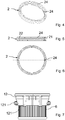
- FIG. 11 shows a perspective view of the FIG Fig. 2 bearing ring shown.
- the bearing ring 2 also has circumferentially arranged support ribs 24 which are formed on an inner surface of the bearing ring 2.
- Fig. 5 shows a sectional view of the in Fig. 2 bearing ring shown.
- the bearing ring 2 has the circumferentially arranged support ribs 24, the H-profile 21 and the U-profile 22.
- Fig. 6 shows a plan view of the in Fig. 2 bearing ring shown.
- the bearing ring 2 is designed to be rotationally symmetrical.
- the support ribs 24 are arranged on an inner surface (not shown) of the bearing ring 2.
- Fig. 7 shows a side view of the in Fig. 1 shown exhaust filter.
- the exhaust air filter 6 has the further housing part 12, which has a plurality of receiving geometries 121.
- the receiving geometries 121 are designed to receive complementary elements (not shown) of a device body housing (not shown) and / or to be positively connected to a rib geometry (not shown) of the housing part (not shown).
- Fig. 8 shows a plan view of the in Fig. 7 shown exhaust filter.
- the receiving geometries 121 which are configured differently, are formed on the further housing part 12.
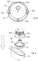
- FIG. 13 shows a perspective view of an assembly step for assembling the FIG Fig. 1 Housing shown including fan, wherein the bearing ring is shown pre-assembled on the fan.
- the housing part 11, the fan 7 and further housing parts 12 are assembled in the direction of the arrow.
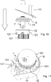
- Fig. 10 shows a side view of the in Fig. 9 assembly step shown in the opposite assembly direction.
- the housing part 11, the fan 7 and further housing parts 12 are assembled in the direction of the arrow.
- FIG. 11 shows a perspective view of the FIG Fig. 9 or 10 manufactured housing.
- the housing 1 has the housing part 11 and the further housing part 12, which is part of the exhaust air filter 6 and has the receiving geometries 121.
- Two of the receiving geometries 121 are designed in such a way that they are positively connected to rib geometries 111 of the housing part 11.
- Fig. 12 shows a further plan view of the in Fig. 11 shown housing.
- the housing part 11 has two rib geometries 111 and the further housing part 12 has two receiving geometries 121, which are positively connected to one another. Furthermore, the further housing part 12 has three further receiving geometries 121.
- FIG. 11 shows an exploded view of a device body housing of the FIG Fig. 1 shown vacuum cleaner.
- the device body housing 8 has a housing insert 81 and a further housing insert 82. Both the device body insert 81 and the further housing insert 82 each have receiving geometries 84 which are designed to be in engagement with the housing or the respective other housing insert 82, 81.
- FIG. 11 shows a partial perspective view of FIG Fig. 1 shown motor capsule.
- the fan 7, from which the fan cover 5 is visible, is arranged in the exhaust air filter 6 with the further housing part 12 in order to form a motor capsule.
- the further receiving geometries 121 shown, when installed in the in Fig. 8 Device body housing shown (not shown) in addition to a support an anti-twist device.
- Fig. 15 shows a perspective partial view of the device body of the in FIG Fig. 1 shown vacuum cleaner.
- the device body 8 partially encloses the motor capsule made up of the exhaust air filter 6 and the fan 7.
- the motor capsule is supported in the respective housing insert 81, 82 and is arranged so as to be secure against rotation.
- FIG. 13 is a perspective view of a partial assembly step for manufacturing the FIG Fig. 1 shown device body.
- the housing 11 has the housing parts 11, 12 connected via the bearing ring (not shown), in the interior of which the fan (not shown) is arranged.
- the housing 1 is inserted into the further housing insert 82 in the direction of the arrow.
- FIG. 13 shows a perspective view of a further assembly step for producing the in FIG Fig. 15 shown device body including housing part 11.
- the housing insert 81 and the housing 1 are moved in the direction of the arrow to the further housing insert 82 and thus mounted.
- FIG. 10 shows a cross-sectional view of FIG Fig. 17 manufactured device body.
- the housing part 12 has a support element 122 which is designed to be supported in the housing insert 81 and the further housing insert 82. Furthermore, the two housing parts 11, 12 are fixed to one another by a circumferential fixing 83.
- the fan 7 has a motor 71 which is configured to rotate a shaft 72 of the fan 7.
- the fan 7 also has an impeller 73 which is arranged on the shaft 72.
- a guide stage 77 is located downstream of the impeller 73 in the direction of flow of the fan. This guide step 77 forms a bearing rib 75 which is mounted in the bearing ring 2.
- FIG. 11 shows another cross-sectional view of the FIG Fig. 18 shown device body.
- the housing part 12 is supported on both sides in the housing insert 81 and the further housing insert 82.
- Fig. 20 shows a further plan view of the in Fig. 18 shown device body.
- the further housing insert 82 is connected to the housing 1 by means of screws 9.
- Fig. 21 shows a further plan view of the in Fig. 18 shown device body.
- the housing insert 81 and the further housing insert 82 are connected to the housing 1 and to one another by means of screws 9.
- FIG. 11 shows a perspective view of the FIG Fig. 1 shown motor capsule.
- the motor capsule is formed from the exhaust air filter 6, which has the further housing part 12, and the fan 7 together with the fan cover 5.
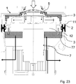
- Fig. 23 shows a partial cross-sectional view of a further vacuum cleaner according to the invention.
- the in Fig. 23 The vacuum cleaner shown corresponds to the one in Fig. 1 shown vacuum cleaner with the difference that a damping element 3 is arranged in the inflow area of the fan 7 and in the outflow area of the fan 7. The air flows in the direction of the arrow.
Landscapes
- Engineering & Computer Science (AREA)
- Mechanical Engineering (AREA)
- Structures Of Non-Positive Displacement Pumps (AREA)
- Electric Suction Cleaners (AREA)
Abstract
Description
- Die Erfindung betrifft einen Staubsauger. Insbesondere betrifft die Erfindung einen Staubsauger mit einem Gebläse, wobei das Gebläse einen Motor, eine Welle, die von dem Motor antreibbar ist, ein Laufrad, welches an der Welle befestigt ist und ein Gebläse-Gehäuse mit einer Gebläsehaube aufweist, das die Gebläse-Bauteile umschließt. Aus einem druckschriftlich nicht belegten Stand der Technik ist bekannt, dass ein derartiges Gebläse im Staubsauger von zwei Lagerelementen, eines in einem Einström- bzw. Ansaugbereich und eines auf einer Aus- bzw. Abströmseite des Gebläses, aufgenommen wird. Es sind daher mehrere Bauteile zur Lagerung des Gebläses notwendig. Diese benötigen Bauraum und verursachen Kosten.
- Der Erfindung stellt sich somit das Problem, einen Staubsauger bereitzustellen, der eine Gebläselagerung mit wenig Kosten und geringem benötigtem Bauraum aufweist.
- Erfindungsgemäß wird dieses Problem durch einen Staubsauger mit den Merkmalen des Patentanspruchs 1 gelöst. Vorteilhafte Ausgestaltungen und Weiterbildungen der Erfindung ergeben sich aus den nachfolgenden Unteransprüchen.
- Die mit der Erfindung erreichbaren Vorteile bestehen neben der Kostengünstigkeit darin, dass wenig Bauteile verwendet werden und diese dabei weniger Bauraum benötigen. Die Bauform ist sehr kompakt, da die Gebläselagerung in die beiden Gehäuseteile des Motorraums integriert ist. Zudem wird durch die erfindungsgemäße Lösung eine gute Luftleistung und Dämmleistung des Staubsauger-Gebläses erreicht.
- Die Erfindung betrifft einen Staubsauger mit einem Gehäuse, einem Gebläse und einem Lagerring, wobei das Gebläse in dem Gehäuse untergebracht ist und das Gehäuse mehrere Gehäuseteile aufweist und das Gebläse auf dem Lagerring lagert, der gleichzeitig als Dichtung zwischen den Gehäuseteilen wirkt. Die Bauweise ist kostengünstig und benötigt wenig Bauraum. Bei dem Gehäuse handelt es sich um das Gehäuse, das den Motorraum umschließt.
- In einer bevorzugten Ausführungsform ist der Lagerring an einem größten Durchmesser des Gebläses angeordnet. Damit besteht weiterhin die Möglichkeit aus dem gleichen Bauteil die Motorraumdichtung zu bilden, welche optimale Dichtergebnisse liefert.
- Bevorzugt weist der Lagerring ein H-Profil auf, so dass er zwei Nuten aufweist. In einer der Nuten des H-Profils ist bevorzugt ein Ende des einen Gehäuseteils und in der anderen Nut des H-Profils ein Ende des weiteren Gehäuseteiles angeordnet. Dadurch wird weiterhin ein gutes Dichtergebnis bereitgestellt. Das System aus Gehäuseteil, weiterem Gehäuseteil und Lagerring weist ausreichend Stabilität auf und das Gebläse ist fest in seiner Position gelagert und hält somit dem laufenden Betrieb des Staubsaugers sowie Stoßbelastungen durch Fall stand. Bevorzugt weist das H-Profil Einführschrägen auf. Die Einführschrägen sind derart ausgebildet sind, dass sie ein Einführen des Gehäuseteils bzw. weiteren Gehäuseteils in die jeweilige Nut erleichtern.
- In einer bevorzugten Ausführungsform weist der Lagerring eine Aufnahmegeometrie zum Aufnehmen eines Teils des Gebläses in Form eines U-Profils auf. Das U-Profil weist eine weitere Nut auf, in der das Teil des Gebläses lagert. Das U-Profil lässt sich im einzelnen Zustand auch bei Übermaß sehr gut auf das Gebläse montieren.
- Bevorzugt weist das Gebläse eine Lagerrippe mit einer Verzahnung auf und ist in der weiteren Nut des U-Profils angeordnet. Die Lagerrippe ist in der weiteren Nut des U-Profils gelagert. Die Verzahnung verhindert ein Verdrehen des Gebläses bei Anlauf und während des Betriebs des Staubsaugers.
- In einer bevorzugten Ausführungsform ist der Lagerring rotationssymmetrisch ausgebildet. Der Lagerring weist im Verbau seinen funktionalen Zustand auf. Der Lagerring ist bevorzugt ein weiches Bauteil, um dichtende und dämpfende Eigenschaften bereitzustellen. Bevorzugt ist der Lagerring aus Gummi beispielsweise EPDM (Ethylen-Propylen-Dien-Kautschuk) gebildet. Er besitzt bevorzugt keine Eigenstabilität. Der Lagerring weist bevorzugt umlaufend angeordnete Stützrippen an einer Innenfläche auf. Der Lagerring ist bevorzugt derart ausgebildet, dass er sich komplett frei mit der weiteren Nut des U-Profils auf die Lagerippe setzen lässt.
- Bevorzugt ist eines der Gehäuseteile als Teil des Abluftfilters ausgebildet. Dadurch können weiterhin Bauteile eingespart werden. Bevorzugt ist das weitere Gehäuseteil als Teil des Abluftfilters ausgebildet und ist der Abluftfilter ausgebildet, das Gebläse zumindest teilweise in seinem Inneren aufzunehmen. Der Abluftfilter bildet so zusammen mit dem Gebläse eine Motorkapsel, die weiterhin mit dem Gehäuseteil über den Lagerring verbunden ist. Diese Motorkapsel aus Gebläse, Lagerring und weiterem Gehäuseteil bietet die Möglichkeit der Vorkonfektionierung und somit die Bildung von unterschiedlichen Varianten in der Gebläse- und Motorausstattung und der Filterausstattung im Hinblick auf unterschiedliche Filtrationsklassen während einer Montage des Staubsaugers.
- Bevorzugt sind das Gebläse und das weitere Gehäuseteil mittels einer Steck- und/oder Rastverbindung verbunden. Das Gebläse weist bevorzugt einen Motor, eine Welle, die von dem Motor antreibbar ist, ein Laufrad, welches an der Welle befestigt ist und ein Gebläse-Gehäuse mit einer Gebläsehaube auf, dass die Gebläse-Bauteile umschließt. Das Gebläse-Gehäuse ist bevorzugt zylinderförmig ausgebildet, wobei sein Durchmesser variieren kann. Das Gebläse-Gehäuse bildet eine Leitstufe des Gebläses aus. Gebläse-Gehäuse und Leitstufe sind dabei einstückig ausgeführt. Bevorzugt weist eine Stirnseite des GebläseGehäuses Öffnungen auf, um einem Luftstrom zur Kühlung des Motors zu erlauben. Auch das weitere Gehäuseteil ist bevorzugt zylinderförmig ausgebildet, wobei der Durchmesser variabel sein kann.
- Der gesamte Motorraum, der durch das Gehäuseteil und das weitere Gehäuseteil begrenzt ist, ist bevorzugt als eine nichtverschraubte Kapsel ausgebildet. Bevorzugt sind all diese Bauteile in Achsrichtung des Gebläses zusammengesetzt. Dadurch wird eine kompakte Bauform erzeugt, deren Bauteile nicht miteinander verschraubt bzw. unverschraubt sind.
- Durch den erfindungsgemäßen Aufbau kann eine Trennung des Über- und Unterdruckraumes nicht direkt an einem Einström- bzw. Ansaugbereich des Gebläses stattfinden. Vielmehr befindet sich ein Freiraum um das Gebläse im Einströmbereich. In einer bevorzugten Ausführungsform ist im Einströmbereich des Gebläses ein Dämpfungselement und/oder ein Dichtungselement angeordnet. Dadurch wird verhindert, dass das Gebläse sich aus dem Freiraum zusätzlich Luft ziehen kann, insbesondere wird diese Sekundärströmung verhindert. Der Freiraum kann mit einem Dämpfungselement in Form eines Schaums oder Vlieses ausgekleidet sein. Alternativ oder zusätzlich kann der Freiraum an der Einströmstelle des Gebläses mit einem Dichtungselement verschlossen sein. Die auskleidenden Dämmelemente oder das Dichtungselement sitzt bevorzugt um den Einströmbereich des Gebläses. Dadurch kann bei Betrieb die einströmende Luft beruhigt werden und somit auch einen positiven akustischen Nutzen bringen. Das Dämpfungselement und/oder das Dichtungselement weisen bevorzugt eine strömungstechnisch günstige Geometrie auf. Das Dämpfungselement und/oder ein Dichtungselement ragt bevorzugt in den Einströmbereich des Gebläses. Dadurch beruhigt es den Luftstrom direkt im Einströmbereich und hat somit einen positiven akustischen Effekt.
- In einer bevorzugten Ausführungsform ist alternativ oder zusätzlich im Aus- bzw. Abströmbereich des Gebläses ein Dämpfungselement angeordnet. Im Ausströmbereich des Gebläses wird die Luft bei Betrieb durch eine mit einer Schaufelgeometrie ausgebildeten Leitstufe aus dem Gebläse geleitet. An dieser Stelle ist bevorzugt das Dämpfungselement bevorzugt benachbart zur Leitstufe angeordnet. Dadurch wird die Luft bei Betrieb gezielt durch das Dämpfungselement geleitet. Dieses wirkt für die chaotisch aus dem Gebläse austretenden Luft wie ein Gleichrichter und beruhigt den Luftstrom und führt somit zu einer Reduktion des Luftrauschens. Zusätzlich führt dieses Beruhigen des Luftstroms zu einer Luftleistungssteigerung in Form von Volumenstromrückgewinnung.
- Im Einströmbereich oder Ausströmbereich angeordnete Dämpfungselemente und/oder Dichtungselemente können identisch sein und können als Gleichteil verwendet werden. Am Einströmbereich ist das Dämpfungselement und/oder Dichtungselement bevorzugt komprimiert angeordnet, während es im Ausströmbereich bevorzugt in seiner Ausgangslage eingesetzt ist.
- Bevorzugt ist im Einströmbereich und/oder Ausströmbereich das Dämmelement in Form eines Schaums angeordnet. Beispielsweise kann das Dämmelement ein Schaumring sein. Bevorzugt ist der Schaum offenporig. Dadurch kann weiterhin ein akustischer Nutzen erzielt werden.
- In einer bevorzugten Ausführungsform weist das Gehäuseteil mindestens eine Rippengeometrie auf, die formschlüssig mit einer Aufnahmegeometrie des weiteren Gehäuseteiles verbunden ist. Dadurch kann die Montage der Motorkapsel in das Gehäuseteil des Motorraums gerichtet erfolgen. Bevorzugt weist das Gehäuseteil mehrere Rippengeometrien auf, so dass eine Fixierung des Gehäuseteils in der Achsrichtung des Gebläses insbesondere über umlaufend am weiteren Gehäuseteil angeordnete Aufnahmegeometrien am weiteren Gehäuseteil erfolgt.
- In einer bevorzugten Ausführungsform weist der Staubsauger weiterhin ein Gerätekorpus-Gehäuse auf, das mehrere Gehäuse-Einsätze aufweist, die das Gehäuse zumindest teilweise umhüllen. Die beiden Gehäuse-Einsätze halten bevorzugt das Gehäuse, das den Motorraum begrenzt, fest zusammen.
- Bevorzugt weist eines der mindestens zwei Gehäuseteile Aufnahmegeometrien auf, die ausgebildet sind, mit komplementären Gegenelementen des Gerätekorpus-Gehäuses in Eingriff zu stehen. Bevorzugt weist das weitere Gehäuseteil die Aufnahmegeometrien auf. Beispielsweise weist es zwei bis sechs Aufnahmegeometrien auf, die umlaufend an einer Außenfläche angeordnet sind. Bevorzugt sind die Aufnahmegeometrien ausgelegt, sich bei der Montage in die beiden Gehäuse-Einsätze des Gerätekorpus-Gehäuse einzufügen. Bevorzugt sind die Aufnahmegeometrien in Achsrichtung des Gebläses mit Spiel ausgelegt, um insbesondere bei möglichen Dichtheitsproblemen die Vorspannung in das H-Profil des Lagerrings zu erhöhen. Neben einer Abstützung in den Gehäusen-Einsätzen sind die Ausfnahmegeometrien bevorzugt derart ausgebildet, dass sie eine Verdrehsicherung bieten.
- In einer bevorzugten Ausführungsform weist eines oder mehrere der Gehäuse-Einsätze Aufnahmegeometrien auf, die ausgebildet sind, jeweils mit komplementären Gegenelementen des anderen Gerätekorpus-Einsatzes, des Gehäuseteils und/oder des weiteren Gehäuseteiles in Eingriff zu stehen. Dadurch sind die beiden Gehäuse-Einsätze miteinander verrastbar. Bevorzugt sind die beiden Gehäuse-Einsätze zusätzlich miteinander verschraubt. Dadurch wird eine endgültige Fixierung bewirkt.
- Das weitere Gehäuseteil weist bevorzugt ein Abstützungselement auf, das ausgebildet ist, sich in dem Gehäuse-Einsatz und dem weiteren Gehäuse-Einsatz abzustützen. Ferner sind das Gehäuseteil und das weitere Gehäuseteil bevorzugt durch eine umlaufende Fixierung aneinander fixiert.
- Bevorzugt handelt es sich bei dem Staubsauger um einen handgeführten Staubsauger. Unter dem Ausdruck "handgeführt" ist zu verstehen, dass der Staubsauger per Hand von dem Nutzer bei Betrieb geführt wird. Bevorzugt ist der Staubsauger als Hand- und/oder Stabstaubsauger ausgebildet. Bevorzugter sind ein Saugrohr, der das Gebläse enthaltende Gerätekorpus, ein Handgriff und optional eine Bodendüse des Staubsaugers in mehreren Staubsaugerkonfigurationen miteinander verbindbar, so dass der Staubsauger als Mehrzweck-Staubsauger ausgebildet ist.
- In einer bevorzugten Ausführungsform weist der Staubsauger einen Akkumulator auf, der ausgebildet ist, das Antriebsaggregat mit Strom zu versorgen.
- Bevorzugt ist der Staubsauger als Zyklon-Staubsauger ausgebildet. Unter dem Begriff "Zyklon-Staubsauger" ist ein Staubsauger zu verstehen, der beutellos ist und in einem in den Staubsauger eintretenden Luftstrom Wirbel und etwaige Verwirbelungen erzeugt werden, wodurch das Sauggut wie z.B. Staubteilchen aufgrund von Fliehkraft in eine vorbestimmte Richtung gedrückt und abgeschieden werden.
- Ein Ausführungsbeispiel der Erfindung ist in den Zeichnungen rein schematisch dargestellt und wird nachfolgend näher beschrieben. Es zeigt schematisch und nicht maßstabsgerecht
- Fig. 1
- eine Teilquerschnittsansicht eines erfindungsgemäßen Staubsaugers;
- Fig. 2
- eine Querschnittsansicht des in
Fig. 1 gezeigten Lagerrings; - Fig. 3
- eine vergrößerte Teilansicht des in
Fig. 1 gezeigten Staubsaugers; - Fig. 4
- eine perspektivische Ansicht des in
Fig. 2 gezeigten Lagerrings; - Fig. 5
- eine Schnittansicht des in
Fig. 2 gezeigten Lagerrings; - Fig. 6
- eine Draufsicht auf den in
Fig. 2 gezeigten Lagerring; - Fig. 7
- eine Seitenansicht des in
Fig. 1 gezeigten Abluftfilters; - Fig. 8
- eine Draufsicht auf den in
Fig. 7 gezeigten Abluftfilter; - Fig. 9
- eine perspektivische Ansicht eines Montageschritts zur Montage des in
Fig. 1 gezeigten Gehäuses samt Gebläse; - Fig. 10
- zeigt eine Seitenansicht des in
Fig. 9 gezeigten Montageschritts in entgegengesetzter Montagerichtung; - Fig. 11
- eine perspektivische Ansicht des in
Fig. 9 oder10 hergestellten Gehäuses; - Fig. 12
- eine Draufsicht auf das in
Fig. 11 gezeigten Gehäuse; - Fig. 13
- eine Explosionsansicht eines Gerätekorpus-Gehäuses des in
Fig. 1 gezeigten Staubsaugers; - Fig. 14
- eine perspektivische Teilansicht der in
Fig. 1 gezeigten Motorkapsel; - Fig. 15
- eine perspektivische Teilansicht eines Gerätekorpus des in
Fig. 1 gezeigten Staubsaugers; - Fig. 16
- eine perspektivische Ansicht eines Teil-Montageschritts zur Herstellung des in
Fig. 15 gezeigten Gerätekorpus; - Fig. 17
- eine perspektivische Ansicht eines Montageschritts zur Herstellung des in
Fig. 15 gezeigten Gerätekorpus; - Fig. 18
- eine Querschnittsansicht des gemäß
Fig. 17 hergestellten Gerätekorpus; - Fig. 19
- eine weitere Querschnittsansicht des in
Fig. 18 gezeigten Gerätekorpus; - Fig. 20
- eine weitere Draufsicht auf den in
Fig. 18 gezeigten Gerätekorpus; - Fig. 21
- eine weitere Draufsicht auf den in
Fig. 18 gezeigten Gerätekorpus; - Fig. 22
- eine perspektivische Ansicht der in
Fig. 1 gezeigten Motorkapsel; und - Fig. 23
- eine Teilquerschnittsansicht eines weiteren erfindungsgemäßen Staubsaugers.
-
Fig. 1 zeigt eine Teilquerschnittsansicht eines erfindungsgemäßen Staubsaugers. Der Staubsauger weist ein Gehäuse 1, das ein Gehäuseteil 11 und ein weiteres Gehäuseteil 12 aufweist. Ferner weist der Staubsauger ein Gebläse 7 mit einem Gebläse-Gehäuse 77, das in dem Gehäuse 1 angeordnet ist, einen Lagerring 2 auf, der an dem Gehäuse 1 angeordnet ist, so dass er beide Gehäuseteile 11, 12 dichtend verbindet. Das Gebläse 7 lagert auf dem Lagerring 2, der gleichzeitig als Dichtung zwischen den Gehäuseteilen 11, 12 wirkt. Dazu weist das Gebläse 7 weiterhin eine Lagerrippe 76 mit einer Verzahnung 75 auf, die auf dem Lagerring 2 lagert. Der Lagerring 2 ist an einem größten Durchmesser des Gebläses 7 angeordnet. Das weitere Gehäuseteil 12 ist Teil eines Abluftfilters 6. Das Gebläse-Gehäuse 77 weist eine Gebläsehaube 5 auf. Zwischen der Gebläsehaube 5 und dem Gehäuseteil 11 existiert ein Freiraum 4. Das Gebläse 7 und das weitere Gehäuseteil bilden eine Motorkapsel. -
Fig. 2 zeigt eine Querschnittsansicht des inFig. 1 gezeigten Lagerrings. Der Lagerring 2 weist ein H-Profil 21 auf, so dass es zwei Nuten aufweist. Der Lagerring 2 weist ferner eine Aufnahmegeometrie zum Aufnehmen eines Teils des Gebläses (nicht gezeigt) in Form eines U-Profils 22 auf, wobei das U-Profil eine weitere Nut ausbildet. Ferner weist der Lagerring 2 vier Einführschrägen 23 auf. Die Einführschrägen 23 sind ausgebildet, ein Einführen des Gehäuseteils 11 und des weiteren Gehäuseteiles 12 zu erleichtern. -
Fig. 3 zeigt eine vergrößerte Teilansicht des inFig. 1 gezeigten Staubsaugers. Das Gebläse 7 weist die Lagerrippe 76 mit der Verzahnung 75 auf, die in der weiteren Nut des U-Profils 22 angeordnet ist. In einer der Nuten des H-Profils 21 ist ein Ende des Gehäuseteils 11 und in der anderen Nut des H-Profils 21 ein Ende des weiteren Gehäuseteiles 12 angeordnet. -
Fig. 4 zeigt eine perspektivische Ansicht des inFig. 2 gezeigten Lagerrings. Der Lagerring 2 weist ferner umlaufend angeordnete Stützrippen 24 auf, die an einer Innenfläche des Lagerrings 2 ausgebildet sind. -
Fig. 5 zeigt eine Schnittansicht des inFig. 2 gezeigten Lagerrings. Der Lagerring 2 weist die umlaufend angeordneten Stützrippen 24, das H-Profil 21 und das U-Profil 22 auf. -
Fig. 6 zeigt eine Draufsicht auf den inFig. 2 gezeigten Lagerring. Der Lagerring 2 ist rotationssymmetrisch ausgebildet. Die Stützrippen 24 sind an einer Innenfläche (nicht gezeigt) des Lagerrings 2 angeordnet. Hier sind die Schnittlinien des Schnitts für die Darstellung gemäßFig. 5 gestrichelt gezeigt. -
Fig. 7 zeigt eine Seitenansicht des inFig. 1 gezeigten Abluftfilters. Der Abluftfilter 6 weist das weitere Gehäuseteil 12 auf, das mehrere Aufnahmegeometrien 121 aufweist. Die Aufnahmegeometrien 121 sind ausgebildet, komplementäre Elemente (nicht gezeigt) eines Geätekorpus-Gehäuses (nicht gezeigt) aufzunehmen und/oder mit einer Rippengeometrie (nicht gezeigt) des Gehäuseteils (nicht gezeigt) formschlüssig verbunden zu werden. -
Fig. 8 zeigt eine Draufsicht auf den inFig. 7 gezeigten Abluftfilter. An dem weiteren Gehäuseteil 12 sind die Aufnahmegeometrien 121 ausgebildet, die verschieden ausgebildet sind. -
Fig. 9 zeigt eine perspektivische Ansicht eines Montageschritts zur Montage des inFig. 1 gezeigten Gehäuses samt Gebläse, wobei der Lagerring am Gebläse vormontiert gezeigt ist. Das Gehäuseteil 11, das Gebläse 7 und weitere Gehäuseteil 12 werden in Pfeilrichtung zusammengefügt. -
Fig. 10 zeigt eine Seitenansicht des inFig. 9 gezeigten Montageschritts in entgegengesetzter Montagerichtung. Das Gehäuseteil 11, das Gebläse 7 und weitere Gehäuseteil 12 werden in Pfeilrichtung zusammengefügt. -
Fig. 11 zeigt eine perspektivische Ansicht des inFig. 9 oder10 hergestellten Gehäuses. Das Gehäuse 1 weist das Gehäuseteil 11 und das weitere Gehäuseteil 12 auf, das Teil des Abluftfilters 6 ist und die Aufnahmegeometrien 121 aufweist. Zwei der Aufnahmegeometrien 121 sind derart ausgebildet, dass sie mit Rippengeometrien 111 des Gehäuseteils 11 formschlüssig verbunden sind. -
Fig. 12 zeigt eine weitere Draufsicht auf den inFig. 11 gezeigte Gehäuse. Das Gehäuseteil 11 weist zwei Rippengeometrien 111 und das weitere Gehäuseteil 12 zwei Aufnmahmegeometrien 121 auf, die formschlüssig miteinander verbunden sind. Weiterhin weist das weitere Gehäuseteil 12 drei weitere Aufnahmegeometrien 121. -
Fig. 13 zeigt eine Explosionsansicht eines Gerätekorpus-Gehäuses des inFig. 1 gezeigten Staubsaugers. Das Gerätekorpus-Gehäuse 8 weist einen Gehäuse-Einsatz 81 und einen weiteren Gehäuse-Einsatz 82 auf. Sowohl der Gerätekorpus-Einsatz 81 als auch der weitere Gehäuse-Einsatz 82 weisen jeweils Aufnahmegeometrien 84 auf, die ausgebildet sind, mit dem Gehäuse oder dem jeweils anderen Gehäuse-Einsatz 82, 81 in Eingriff zu stehen. -
Fig. 14 zeigt eine perspektivische Teilansicht der inFig. 1 gezeigten Motorkapsel. Das Gebläse 7, von dem die Gebläsehaube 5 sichtbar ist, ist in den Abluftfilter 6 mit dem weiteren Gehäuseteil 12 angeordnet, um eine Motorkapsel zu bilden. Die gezeigten weiteren Aufnahmegeometrien 121 bieten bei Einbau in das inFig. 8 gezeigte Gerätekorpus-Gehäuse (nicht gezeigt) zusätzlich zu einer Abstützung eine Verdrehsicherung. -
Fig. 15 zeigt eine perspektivische Teilansicht des Gerätekorpus des inFig. 1 gezeigten Staubsaugers. Der Gerätekorpus 8 umschließt teilweise die Motorkapsel aus Abluftfilter 6 und Gebläse 7. Durch die Aufnahmegeometrien 121 ist die Motorkapsel im jeweiligen Gehäuse-Einsatz 81, 82 abgestützt und verdrehsicher angeordnet. -
Fig. 16 zeigt eine perspektivische Ansicht eines Teil-Montageschritts zur Herstellung des inFig. 1 gezeigten Gerätekorpus. Das Gehäuse 11 weist die über den Lagerring (nicht gezeigt) verbundenen Gehäuseteile 11, 12 auf, in deren Inneren das Gebläse (nicht gezeigt) angeordnet ist. Das Gehäuse 1 wird in Pfeilrichtung in den weiteren Gehäuse-Einsatz 82 eingebracht. -
Fig. 17 zeigt eine perspektivische Ansicht eines weiteren Montageschritts zur Herstellung des inFig. 15 gezeigten Gerätekorpus samt Gehäuseteil 11. Der Gehäuse-Einsatz 81 und das Gehäuse 1 werden in Pfeilrichtung zu dem weiteren Gehäuse-Einsatz 82 bewegt und somit montiert. -
Fig. 18 zeigt eine Querschnittsansicht des gemäßFig. 17 hergestellten Gerätekorpus. Das Gehäuseteil 12 weist ein Abstützungselement 122 auf, das ausgebildet ist, sich in dem Gehäuse-Einsatz 81 und dem weiteren Gehäuse-Einsatz 82 abzustützen. Ferner sind die beiden Gehäuseteile 11, 12 durch eine umlaufende Fixierung 83 aneinander fixiert. Das Gebläse 7 weist einen Motor 71, der ausgebildet ist, eine Welle 72 des Gebläses 7 zu drehen. Ferner weist das Gebläse 7 ein Laufrad 73 auf, das an der Welle 72 angeordnet ist. - Dem Laufrad 73 ist in Strömungsrichtung des Gebläses eine Leitstufe 77 nachgelagert. Diese Leitstufe 77 bildet eine Lagerrippe 75 aus, welche in dem Lagerring 2 gelagert ist.
-
Fig. 19 zeigt eine weitere Querschnittsansicht des inFig. 18 gezeigten Gerätekorpus. Das Gehäuseteil 12 stützt sich beidseitig in dem Gehäuse-Einsatz 81 und dem weiteren Gehäuse-Einsatz 82 ab. -
Fig. 20 zeigt eine weitere Draufsicht auf den inFig. 18 gezeigten Gerätekorpus. Der weitere Gehäuse-Einsatz 82 ist mit dem Gehäuse 1 mittels Schrauben 9 verbunden. -
Fig. 21 zeigt eine weitere Draufsicht auf den inFig. 18 gezeigten Gerätekorpus. Der Gehäuse-Einsatz 81 und der weitere Gehäuse-Einsatz 82 sind mit dem Gehäuse 1 und miteinander mittels Schrauben 9 verbunden. -
Fig. 22 zeigt eine perspektivische Ansicht der inFig. 1 gezeigten Motorkapsel. Die Motorkapsel ist aus dem Abluftfilter 6, der das weitere Gehäuseteil 12 aufweist, und dem Gebläse 7 samt Gebläsehaube 5, gebildet. -
Fig. 23 zeigt eine Teilquerschnittsansicht eines weiteren erfindungsgemäßen Staubsaugers. Der inFig. 23 gezeigte Staubsauger entspricht dem inFig. 1 gezeigten Staubsauger mit dem Unterschied, dass im Einströmbereich des Gebläses 7 und im Ausströmbereich des Gebläses 7 jeweils ein Dämpfungselement 3 angeordnet ist. Die Luft strömt in Pfeilrichtung. -
- 1
- Gehäuse
- 11
- Gehäuseteil
- 111
- Rippengeometrie
- 12
- weiteres Gehäuseteil
- 121
- Aufnahmegeometrie
- 122
- Abstützungselement
- 123
- weitere Aufnahmegeometrie
- 2
- Lagerring
- 21
- H-Profil
- 22
- U-Profil
- 23
- Einführschräge
- 24
- Stützrippe
- 3
- Dämpfungselement
- 4
- Freiraum
- 5
- Gebläsehaube
- 6
- Abluftfilter
- 7
- Gebläse
- 71
- Motor
- 72
- Welle
- 73
- Laufrad
- 75
- Lagerrippe
- 76
- Verzahnung
- 77
- Gebläse-Gehäuse und Leitstufe
- 8
- Gerätekorpus-Gehäuse
- 81
- Gehäuse-Einsatz
- 82
- weitere Gehäuse-Einsatz
- 83
- Fixierung
- 84
- Aufnahmegeometrie
- 9
- Schraube
- 10
- Dämpfungselement
Claims (12)
- Staubsauger mit einem Gehäuse (1), einem Gebläse (7) und einem Lagerring (2), wobei das Gebläse (7) in dem Gehäuse (1) untergebracht ist und das Gehäuse (1) mehrere Gehäuseteile (11, 12) aufweist und das Gebläse (7) auf dem Lagerring (2) lagert, der gleichzeitig als Dichtung zwischen den Gehäuseteilen (11, 12) wirkt.
- Staubsauger nach Anspruch 1, dadurch gekennzeichnet, dass der Lagerring (2) an einem größten Durchmesser des Gebläses (7) angeordnet ist.
- Staubsauger nach Anspruch 1 oder 2, dadurch gekennzeichnet, dass der Lagerring (2) ein H-Profil (21) aufweist, so dass es zwei Nuten aufweist, und in einer der Nuten des H-Profils (21) ein Ende des Gehäuseteils (11) und in der anderen Nut des H-Profils (21) ein Ende des weiteren Gehäuseteils (12) angeordnet ist.
- Staubsauger nach einem der vorangehenden Ansprüche 2, dadurch gekennzeichnet, dass der Lagerring (2) eine Aufnahmegeometrie zum Aufnehmen eines Teils des Gebläses (7) in Form eines U-Profils (22) aufweist.
- Staubsauger nach Anspruch 4, dadurch gekennzeichnet, dass das Gebläse (7) eine Lagerrippe (75) mit einer Verzahnung (76) aufweist und in der weiteren Nut des U-Profils (22) angeordnet ist
- Staubsauger nach einem der vorangehenden Ansprüche, dadurch gekennzeichnet, dass der Lagerring (2) rotationssymmetrisch ausgebildet ist.
- Staubsauger nach einem der vorangehenden Ansprüche, dadurch gekennzeichnet, dass eines der Gehäuseteile (12) als Teil des Abluftfilters (6) ausgebildet ist.
- Staubsauger nach einem der vorangehenden Ansprüche, dadurch gekennzeichnet, dass im Einströmbereich des Gebläses (7) und/oder im Ausströmbereich des Gebläses (7) ein Dämpfungselement (3) angeordnet ist.
- Staubsauger nach einem der vorangehenden Ansprüche, dadurch gekennzeichnet, dass das Gehäuseteil (11) mindestens eine Rippengeometrie (111) aufweist, die formschlüssig mit einer Aufnahmegeometrie (121) des weiteren Gehäuseteiles (12) verbunden ist.
- Staubsauger nach einem der vorangehenden Ansprüche, gekennzeichnet durch ein Gerätekorpus-Gehäuse (8), das mehrere Gehäuse-Einsätze (81, 82) aufweist, die das Gehäuse (1) zumindest teilweise umhüllen.
- Staubsauger nach Anspruch 10, dadurch gekennzeichnet, dass eines oder mehrere der Gehäuse-Einsätze (81, 82) Aufnahmegeometrien aufweist, die ausgebildet sind, jeweils mit komplementären Gegenelementen des anderen Gerätekorpus-Einsatzes (82, 81), des Gehäuseteiles (11) und/oder des weiteren Gehäuseteiles (12) in Eingriff zu stehen.
- Staubsauger nach Anspruch 10 oder 11, dadurch gekennzeichnet, dass eines der mindestens zwei Gehäuseteile (12) Aufnahmegeometrien (121) aufweist, die ausgebildet sind, mit weiteren komplementären Gegenelementen des Gerätekorpus-Gehäuses (8) in Eingriff zu stehen.
Applications Claiming Priority (1)
| Application Number | Priority Date | Filing Date | Title |
|---|---|---|---|
| DE102019121489.0A DE102019121489A1 (de) | 2019-08-09 | 2019-08-09 | Staubsauger |
Publications (2)
| Publication Number | Publication Date |
|---|---|
| EP3772312A1 true EP3772312A1 (de) | 2021-02-10 |
| EP3772312B1 EP3772312B1 (de) | 2022-11-23 |
Family
ID=71620220
Family Applications (1)
| Application Number | Title | Priority Date | Filing Date |
|---|---|---|---|
| EP20185842.0A Active EP3772312B1 (de) | 2019-08-09 | 2020-07-15 | Staubsauger |
Country Status (2)
| Country | Link |
|---|---|
| EP (1) | EP3772312B1 (de) |
| DE (1) | DE102019121489A1 (de) |
Citations (3)
| Publication number | Priority date | Publication date | Assignee | Title |
|---|---|---|---|---|
| GB523367A (en) * | 1938-01-19 | 1940-07-12 | Paul Linke | Improvements in or relating to joints for vacuum cleaner casings |
| DE970885C (de) * | 1949-11-09 | 1958-11-06 | Mauz & Pfeiffer Elektro Appbau | Elastische Aufhaengung eines ein Geblaese antreibenden Elektromotors |
| JP2001061728A (ja) * | 1999-08-31 | 2001-03-13 | Hitachi Ltd | 電気掃除機 |
-
2019
- 2019-08-09 DE DE102019121489.0A patent/DE102019121489A1/de active Pending
-
2020
- 2020-07-15 EP EP20185842.0A patent/EP3772312B1/de active Active
Patent Citations (3)
| Publication number | Priority date | Publication date | Assignee | Title |
|---|---|---|---|---|
| GB523367A (en) * | 1938-01-19 | 1940-07-12 | Paul Linke | Improvements in or relating to joints for vacuum cleaner casings |
| DE970885C (de) * | 1949-11-09 | 1958-11-06 | Mauz & Pfeiffer Elektro Appbau | Elastische Aufhaengung eines ein Geblaese antreibenden Elektromotors |
| JP2001061728A (ja) * | 1999-08-31 | 2001-03-13 | Hitachi Ltd | 電気掃除機 |
Also Published As
| Publication number | Publication date |
|---|---|
| DE102019121489A1 (de) | 2021-02-11 |
| EP3772312B1 (de) | 2022-11-23 |
Similar Documents
| Publication | Publication Date | Title |
|---|---|---|
| DE19712228B4 (de) | Befestigungsvorrichtung für einen Gebläsemotor | |
| EP1447898B1 (de) | Aussenläufermotor | |
| DE102013209801B4 (de) | Tür-reglerstruktur mit integriertem vorhang | |
| DE102007052684A1 (de) | Handwerkzeugmaschine | |
| EP2510861B1 (de) | Motoranordnung für ein elektromotorisch angetriebenes Haushaltsgerät | |
| EP3460962B1 (de) | Antrieb | |
| DE1403502A1 (de) | Anordnung zum Aufhaengen einer Motor- und Geblaeseeinheit | |
| EP3176920A2 (de) | Abdeckvorrichtung für ein elektronikgehäuse eines elektromotors | |
| DE202005011514U1 (de) | Ventilator für Computer | |
| EP3772312B1 (de) | Staubsauger | |
| DE102014116727A1 (de) | Lüftereinheit mit einem Lüftergehäuse | |
| DE10148510C1 (de) | Dichtung zum Einsatz in einer Gebläseanordnung | |
| DE4222264C2 (de) | Kühlvorrichtung für ein Kraftfahrzeug | |
| DE2649181A1 (de) | Belueftungseinrichtung fuer elektrische maschinen | |
| DE102016215571B4 (de) | Sitz mit einer Befestigungsanordnung eines Elektromotors | |
| DE102015208473A1 (de) | Gebläseeinrichtung | |
| DE102010062325A1 (de) | Riemenantrieb mit Torsionsdämpfer | |
| EP3205249B1 (de) | Staubsauger, insbesondere handstaubsauger | |
| EP1867265A2 (de) | Staubsauger | |
| DE102004015241B4 (de) | Luftgekühlte elektrische Maschine | |
| DE102007039814B4 (de) | Befestigungsvorrichtung für Gebläsemotor sowie Fahrzeuggebläse | |
| EP1477346A2 (de) | Entkoppeltes Gebläse | |
| EP1633457A1 (de) | Ansaugluftfilter | |
| DE19907910A1 (de) | Lüfterrad | |
| DE202007018626U1 (de) | Gebläseeinrichtung |
Legal Events
| Date | Code | Title | Description |
|---|---|---|---|
| PUAI | Public reference made under article 153(3) epc to a published international application that has entered the european phase |
Free format text: ORIGINAL CODE: 0009012 |
|
| STAA | Information on the status of an ep patent application or granted ep patent |
Free format text: STATUS: THE APPLICATION HAS BEEN PUBLISHED |
|
| STAA | Information on the status of an ep patent application or granted ep patent |
Free format text: STATUS: REQUEST FOR EXAMINATION WAS MADE |
|
| AK | Designated contracting states |
Kind code of ref document: A1 Designated state(s): AL AT BE BG CH CY CZ DE DK EE ES FI FR GB GR HR HU IE IS IT LI LT LU LV MC MK MT NL NO PL PT RO RS SE SI SK SM TR |
|
| AX | Request for extension of the european patent |
Extension state: BA ME |
|
| 17P | Request for examination filed |
Effective date: 20210115 |
|
| RBV | Designated contracting states (corrected) |
Designated state(s): AL AT BE BG CH CY CZ DE DK EE ES FI FR GB GR HR HU IE IS IT LI LT LU LV MC MK MT NL NO PL PT RO RS SE SI SK SM TR |
|
| RIC1 | Information provided on ipc code assigned before grant |
Ipc: A47L 9/00 20060101ALI20220609BHEP Ipc: A47L 9/22 20060101AFI20220609BHEP |
|
| GRAP | Despatch of communication of intention to grant a patent |
Free format text: ORIGINAL CODE: EPIDOSNIGR1 |
|
| STAA | Information on the status of an ep patent application or granted ep patent |
Free format text: STATUS: GRANT OF PATENT IS INTENDED |
|
| INTG | Intention to grant announced |
Effective date: 20220718 |
|
| GRAS | Grant fee paid |
Free format text: ORIGINAL CODE: EPIDOSNIGR3 |
|
| GRAA | (expected) grant |
Free format text: ORIGINAL CODE: 0009210 |
|
| STAA | Information on the status of an ep patent application or granted ep patent |
Free format text: STATUS: THE PATENT HAS BEEN GRANTED |
|
| AK | Designated contracting states |
Kind code of ref document: B1 Designated state(s): AL AT BE BG CH CY CZ DE DK EE ES FI FR GB GR HR HU IE IS IT LI LT LU LV MC MK MT NL NO PL PT RO RS SE SI SK SM TR |
|
| REG | Reference to a national code |
Ref country code: DE Ref legal event code: R084 Ref document number: 502020002037 Country of ref document: DE Ref country code: GB Ref legal event code: FG4D Free format text: NOT ENGLISH |
|
| REG | Reference to a national code |
Ref country code: CH Ref legal event code: EP |
|
| REG | Reference to a national code |
Ref country code: AT Ref legal event code: REF Ref document number: 1532617 Country of ref document: AT Kind code of ref document: T Effective date: 20221215 Ref country code: DE Ref legal event code: R096 Ref document number: 502020002037 Country of ref document: DE |
|
| REG | Reference to a national code |
Ref country code: IE Ref legal event code: FG4D Free format text: LANGUAGE OF EP DOCUMENT: GERMAN |
|
| REG | Reference to a national code |
Ref country code: GB Ref legal event code: 746 Effective date: 20221223 |
|
| REG | Reference to a national code |
Ref country code: LT Ref legal event code: MG9D |
|
| REG | Reference to a national code |
Ref country code: NL Ref legal event code: MP Effective date: 20221123 |
|
| PG25 | Lapsed in a contracting state [announced via postgrant information from national office to epo] |
Ref country code: SE Free format text: LAPSE BECAUSE OF FAILURE TO SUBMIT A TRANSLATION OF THE DESCRIPTION OR TO PAY THE FEE WITHIN THE PRESCRIBED TIME-LIMIT Effective date: 20221123 Ref country code: PT Free format text: LAPSE BECAUSE OF FAILURE TO SUBMIT A TRANSLATION OF THE DESCRIPTION OR TO PAY THE FEE WITHIN THE PRESCRIBED TIME-LIMIT Effective date: 20230323 Ref country code: NO Free format text: LAPSE BECAUSE OF FAILURE TO SUBMIT A TRANSLATION OF THE DESCRIPTION OR TO PAY THE FEE WITHIN THE PRESCRIBED TIME-LIMIT Effective date: 20230223 Ref country code: LT Free format text: LAPSE BECAUSE OF FAILURE TO SUBMIT A TRANSLATION OF THE DESCRIPTION OR TO PAY THE FEE WITHIN THE PRESCRIBED TIME-LIMIT Effective date: 20221123 Ref country code: FI Free format text: LAPSE BECAUSE OF FAILURE TO SUBMIT A TRANSLATION OF THE DESCRIPTION OR TO PAY THE FEE WITHIN THE PRESCRIBED TIME-LIMIT Effective date: 20221123 Ref country code: ES Free format text: LAPSE BECAUSE OF FAILURE TO SUBMIT A TRANSLATION OF THE DESCRIPTION OR TO PAY THE FEE WITHIN THE PRESCRIBED TIME-LIMIT Effective date: 20221123 |
|
| PG25 | Lapsed in a contracting state [announced via postgrant information from national office to epo] |
Ref country code: RS Free format text: LAPSE BECAUSE OF FAILURE TO SUBMIT A TRANSLATION OF THE DESCRIPTION OR TO PAY THE FEE WITHIN THE PRESCRIBED TIME-LIMIT Effective date: 20221123 Ref country code: PL Free format text: LAPSE BECAUSE OF FAILURE TO SUBMIT A TRANSLATION OF THE DESCRIPTION OR TO PAY THE FEE WITHIN THE PRESCRIBED TIME-LIMIT Effective date: 20221123 Ref country code: LV Free format text: LAPSE BECAUSE OF FAILURE TO SUBMIT A TRANSLATION OF THE DESCRIPTION OR TO PAY THE FEE WITHIN THE PRESCRIBED TIME-LIMIT Effective date: 20221123 Ref country code: IS Free format text: LAPSE BECAUSE OF FAILURE TO SUBMIT A TRANSLATION OF THE DESCRIPTION OR TO PAY THE FEE WITHIN THE PRESCRIBED TIME-LIMIT Effective date: 20230323 Ref country code: HR Free format text: LAPSE BECAUSE OF FAILURE TO SUBMIT A TRANSLATION OF THE DESCRIPTION OR TO PAY THE FEE WITHIN THE PRESCRIBED TIME-LIMIT Effective date: 20221123 Ref country code: GR Free format text: LAPSE BECAUSE OF FAILURE TO SUBMIT A TRANSLATION OF THE DESCRIPTION OR TO PAY THE FEE WITHIN THE PRESCRIBED TIME-LIMIT Effective date: 20230224 |
|
| PG25 | Lapsed in a contracting state [announced via postgrant information from national office to epo] |
Ref country code: NL Free format text: LAPSE BECAUSE OF FAILURE TO SUBMIT A TRANSLATION OF THE DESCRIPTION OR TO PAY THE FEE WITHIN THE PRESCRIBED TIME-LIMIT Effective date: 20221123 |
|
| P01 | Opt-out of the competence of the unified patent court (upc) registered |
Effective date: 20230528 |
|
| PG25 | Lapsed in a contracting state [announced via postgrant information from national office to epo] |
Ref country code: SM Free format text: LAPSE BECAUSE OF FAILURE TO SUBMIT A TRANSLATION OF THE DESCRIPTION OR TO PAY THE FEE WITHIN THE PRESCRIBED TIME-LIMIT Effective date: 20221123 Ref country code: RO Free format text: LAPSE BECAUSE OF FAILURE TO SUBMIT A TRANSLATION OF THE DESCRIPTION OR TO PAY THE FEE WITHIN THE PRESCRIBED TIME-LIMIT Effective date: 20221123 Ref country code: EE Free format text: LAPSE BECAUSE OF FAILURE TO SUBMIT A TRANSLATION OF THE DESCRIPTION OR TO PAY THE FEE WITHIN THE PRESCRIBED TIME-LIMIT Effective date: 20221123 Ref country code: DK Free format text: LAPSE BECAUSE OF FAILURE TO SUBMIT A TRANSLATION OF THE DESCRIPTION OR TO PAY THE FEE WITHIN THE PRESCRIBED TIME-LIMIT Effective date: 20221123 Ref country code: CZ Free format text: LAPSE BECAUSE OF FAILURE TO SUBMIT A TRANSLATION OF THE DESCRIPTION OR TO PAY THE FEE WITHIN THE PRESCRIBED TIME-LIMIT Effective date: 20221123 |
|
| REG | Reference to a national code |
Ref country code: DE Ref legal event code: R097 Ref document number: 502020002037 Country of ref document: DE |
|
| PG25 | Lapsed in a contracting state [announced via postgrant information from national office to epo] |
Ref country code: SK Free format text: LAPSE BECAUSE OF FAILURE TO SUBMIT A TRANSLATION OF THE DESCRIPTION OR TO PAY THE FEE WITHIN THE PRESCRIBED TIME-LIMIT Effective date: 20221123 Ref country code: AL Free format text: LAPSE BECAUSE OF FAILURE TO SUBMIT A TRANSLATION OF THE DESCRIPTION OR TO PAY THE FEE WITHIN THE PRESCRIBED TIME-LIMIT Effective date: 20221123 |
|
| PLBE | No opposition filed within time limit |
Free format text: ORIGINAL CODE: 0009261 |
|
| STAA | Information on the status of an ep patent application or granted ep patent |
Free format text: STATUS: NO OPPOSITION FILED WITHIN TIME LIMIT |
|
| 26N | No opposition filed |
Effective date: 20230824 |
|
| PG25 | Lapsed in a contracting state [announced via postgrant information from national office to epo] |
Ref country code: SI Free format text: LAPSE BECAUSE OF FAILURE TO SUBMIT A TRANSLATION OF THE DESCRIPTION OR TO PAY THE FEE WITHIN THE PRESCRIBED TIME-LIMIT Effective date: 20221123 |
|
| PG25 | Lapsed in a contracting state [announced via postgrant information from national office to epo] |
Ref country code: MC Free format text: LAPSE BECAUSE OF FAILURE TO SUBMIT A TRANSLATION OF THE DESCRIPTION OR TO PAY THE FEE WITHIN THE PRESCRIBED TIME-LIMIT Effective date: 20221123 |
|
| PG25 | Lapsed in a contracting state [announced via postgrant information from national office to epo] |
Ref country code: MC Free format text: LAPSE BECAUSE OF FAILURE TO SUBMIT A TRANSLATION OF THE DESCRIPTION OR TO PAY THE FEE WITHIN THE PRESCRIBED TIME-LIMIT Effective date: 20221123 |
|
| REG | Reference to a national code |
Ref country code: CH Ref legal event code: PL |
|
| REG | Reference to a national code |
Ref country code: BE Ref legal event code: MM Effective date: 20230731 |
|
| PG25 | Lapsed in a contracting state [announced via postgrant information from national office to epo] |
Ref country code: LU Free format text: LAPSE BECAUSE OF NON-PAYMENT OF DUE FEES Effective date: 20230715 |
|
| PG25 | Lapsed in a contracting state [announced via postgrant information from national office to epo] |
Ref country code: LU Free format text: LAPSE BECAUSE OF NON-PAYMENT OF DUE FEES Effective date: 20230715 |
|
| REG | Reference to a national code |
Ref country code: IE Ref legal event code: MM4A |
|
| PG25 | Lapsed in a contracting state [announced via postgrant information from national office to epo] |
Ref country code: CH Free format text: LAPSE BECAUSE OF NON-PAYMENT OF DUE FEES Effective date: 20230731 |
|
| PG25 | Lapsed in a contracting state [announced via postgrant information from national office to epo] |
Ref country code: BE Free format text: LAPSE BECAUSE OF NON-PAYMENT OF DUE FEES Effective date: 20230731 |
|
| PG25 | Lapsed in a contracting state [announced via postgrant information from national office to epo] |
Ref country code: IE Free format text: LAPSE BECAUSE OF NON-PAYMENT OF DUE FEES Effective date: 20230715 |
|
| PG25 | Lapsed in a contracting state [announced via postgrant information from national office to epo] |
Ref country code: IE Free format text: LAPSE BECAUSE OF NON-PAYMENT OF DUE FEES Effective date: 20230715 |
|
| PG25 | Lapsed in a contracting state [announced via postgrant information from national office to epo] |
Ref country code: BG Free format text: LAPSE BECAUSE OF FAILURE TO SUBMIT A TRANSLATION OF THE DESCRIPTION OR TO PAY THE FEE WITHIN THE PRESCRIBED TIME-LIMIT Effective date: 20221123 |
|
| PG25 | Lapsed in a contracting state [announced via postgrant information from national office to epo] |
Ref country code: BG Free format text: LAPSE BECAUSE OF FAILURE TO SUBMIT A TRANSLATION OF THE DESCRIPTION OR TO PAY THE FEE WITHIN THE PRESCRIBED TIME-LIMIT Effective date: 20221123 |
|
| PG25 | Lapsed in a contracting state [announced via postgrant information from national office to epo] |
Ref country code: CY Free format text: LAPSE BECAUSE OF FAILURE TO SUBMIT A TRANSLATION OF THE DESCRIPTION OR TO PAY THE FEE WITHIN THE PRESCRIBED TIME-LIMIT; INVALID AB INITIO Effective date: 20200715 |
|
| PG25 | Lapsed in a contracting state [announced via postgrant information from national office to epo] |
Ref country code: HU Free format text: LAPSE BECAUSE OF FAILURE TO SUBMIT A TRANSLATION OF THE DESCRIPTION OR TO PAY THE FEE WITHIN THE PRESCRIBED TIME-LIMIT; INVALID AB INITIO Effective date: 20200715 |
|
| PGFP | Annual fee paid to national office [announced via postgrant information from national office to epo] |
Ref country code: DE Payment date: 20250731 Year of fee payment: 6 |
|
| PGFP | Annual fee paid to national office [announced via postgrant information from national office to epo] |
Ref country code: TR Payment date: 20250703 Year of fee payment: 6 Ref country code: IT Payment date: 20250721 Year of fee payment: 6 |
|
| PGFP | Annual fee paid to national office [announced via postgrant information from national office to epo] |
Ref country code: GB Payment date: 20250722 Year of fee payment: 6 |
|
| PGFP | Annual fee paid to national office [announced via postgrant information from national office to epo] |
Ref country code: AT Payment date: 20251020 Year of fee payment: 5 Ref country code: FR Payment date: 20250725 Year of fee payment: 6 |