EP3770286A1 - Verfahren und vorrichtung zum trennen und schmelzen von bleiabfallgittern beim recyceln von blei-säure-abfallakkumulator - Google Patents
Verfahren und vorrichtung zum trennen und schmelzen von bleiabfallgittern beim recyceln von blei-säure-abfallakkumulator Download PDFInfo
- Publication number
- EP3770286A1 EP3770286A1 EP19793489.6A EP19793489A EP3770286A1 EP 3770286 A1 EP3770286 A1 EP 3770286A1 EP 19793489 A EP19793489 A EP 19793489A EP 3770286 A1 EP3770286 A1 EP 3770286A1
- Authority
- EP
- European Patent Office
- Prior art keywords
- lead
- ash
- waste
- grid
- copper
- Prior art date
- Legal status (The legal status is an assumption and is not a legal conclusion. Google has not performed a legal analysis and makes no representation as to the accuracy of the status listed.)
- Withdrawn
Links
- 239000002699 waste material Substances 0.000 title claims abstract description 64
- 238000003860 storage Methods 0.000 title claims abstract description 35
- 239000002253 acid Substances 0.000 title claims abstract description 34
- 238000002844 melting Methods 0.000 title claims abstract description 24
- 230000008018 melting Effects 0.000 title claims abstract description 24
- 238000000034 method Methods 0.000 title claims abstract description 18
- 238000004064 recycling Methods 0.000 title claims abstract description 18
- XLYOFNOQVPJJNP-UHFFFAOYSA-N water Substances O XLYOFNOQVPJJNP-UHFFFAOYSA-N 0.000 claims abstract description 90
- 238000003723 Smelting Methods 0.000 claims abstract description 77
- 238000001035 drying Methods 0.000 claims abstract description 40
- 239000007788 liquid Substances 0.000 claims abstract description 29
- 230000004888 barrier function Effects 0.000 claims abstract description 27
- 238000007599 discharging Methods 0.000 claims abstract description 25
- UGFAIRIUMAVXCW-UHFFFAOYSA-N Carbon monoxide Chemical compound [O+]#[C-] UGFAIRIUMAVXCW-UHFFFAOYSA-N 0.000 claims abstract description 19
- 239000003546 flue gas Substances 0.000 claims abstract description 19
- 238000011010 flushing procedure Methods 0.000 claims abstract description 15
- 239000000428 dust Substances 0.000 claims abstract description 13
- 230000007306 turnover Effects 0.000 claims abstract description 13
- RYGMFSIKBFXOCR-UHFFFAOYSA-N Copper Chemical compound [Cu] RYGMFSIKBFXOCR-UHFFFAOYSA-N 0.000 claims description 34
- 229910052802 copper Inorganic materials 0.000 claims description 34
- 239000010949 copper Substances 0.000 claims description 34
- 239000002893 slag Substances 0.000 claims description 28
- 239000000463 material Substances 0.000 claims description 13
- 239000002002 slurry Substances 0.000 claims description 13
- 238000007667 floating Methods 0.000 claims description 12
- 230000008878 coupling Effects 0.000 claims description 10
- 238000010168 coupling process Methods 0.000 claims description 10
- 238000005859 coupling reaction Methods 0.000 claims description 10
- 238000003825 pressing Methods 0.000 claims description 8
- 230000009471 action Effects 0.000 claims description 7
- 239000003638 chemical reducing agent Substances 0.000 claims description 7
- 230000008569 process Effects 0.000 claims description 7
- 229910045601 alloy Inorganic materials 0.000 claims description 6
- 239000000956 alloy Substances 0.000 claims description 6
- 239000002918 waste heat Substances 0.000 claims description 5
- 238000004891 communication Methods 0.000 claims description 4
- 238000000926 separation method Methods 0.000 claims description 4
- 229910000831 Steel Inorganic materials 0.000 claims description 3
- 238000004321 preservation Methods 0.000 claims description 3
- 239000007921 spray Substances 0.000 claims description 3
- 238000005507 spraying Methods 0.000 claims description 3
- 239000010959 steel Substances 0.000 claims description 3
- 239000002351 wastewater Substances 0.000 claims description 3
- 229910000464 lead oxide Inorganic materials 0.000 description 14
- YEXPOXQUZXUXJW-UHFFFAOYSA-N oxolead Chemical compound [Pb]=O YEXPOXQUZXUXJW-UHFFFAOYSA-N 0.000 description 12
- 238000004519 manufacturing process Methods 0.000 description 10
- 238000010586 diagram Methods 0.000 description 7
- 230000005484 gravity Effects 0.000 description 3
- 239000012535 impurity Substances 0.000 description 3
- ATJFFYVFTNAWJD-UHFFFAOYSA-N Tin Chemical compound [Sn] ATJFFYVFTNAWJD-UHFFFAOYSA-N 0.000 description 2
- 229910052787 antimony Inorganic materials 0.000 description 2
- WATWJIUSRGPENY-UHFFFAOYSA-N antimony atom Chemical compound [Sb] WATWJIUSRGPENY-UHFFFAOYSA-N 0.000 description 2
- 238000004134 energy conservation Methods 0.000 description 2
- 238000004880 explosion Methods 0.000 description 2
- 230000036541 health Effects 0.000 description 2
- 239000002184 metal Substances 0.000 description 2
- 229910052751 metal Inorganic materials 0.000 description 2
- 230000032258 transport Effects 0.000 description 2
- 206010027439 Metal poisoning Diseases 0.000 description 1
- 229910000978 Pb alloy Inorganic materials 0.000 description 1
- HCHKCACWOHOZIP-UHFFFAOYSA-N Zinc Chemical compound [Zn] HCHKCACWOHOZIP-UHFFFAOYSA-N 0.000 description 1
- 230000009286 beneficial effect Effects 0.000 description 1
- 230000000903 blocking effect Effects 0.000 description 1
- 239000000109 continuous material Substances 0.000 description 1
- 238000010924 continuous production Methods 0.000 description 1
- 230000000694 effects Effects 0.000 description 1
- 239000003792 electrolyte Substances 0.000 description 1
- 239000012065 filter cake Substances 0.000 description 1
- 239000007789 gas Substances 0.000 description 1
- 208000008127 lead poisoning Diseases 0.000 description 1
- WABPQHHGFIMREM-UHFFFAOYSA-N lead(0) Chemical compound [Pb] WABPQHHGFIMREM-UHFFFAOYSA-N 0.000 description 1
- DNHVXYDGZKWYNU-UHFFFAOYSA-N lead;hydrate Chemical compound O.[Pb] DNHVXYDGZKWYNU-UHFFFAOYSA-N 0.000 description 1
- 150000002739 metals Chemical class 0.000 description 1
- 239000000843 powder Substances 0.000 description 1
- 238000002360 preparation method Methods 0.000 description 1
- 238000000746 purification Methods 0.000 description 1
- 239000002994 raw material Substances 0.000 description 1
- 238000007670 refining Methods 0.000 description 1
- 239000000725 suspension Substances 0.000 description 1
- 239000002341 toxic gas Substances 0.000 description 1
- 238000009834 vaporization Methods 0.000 description 1
- 230000008016 vaporization Effects 0.000 description 1
- 238000005406 washing Methods 0.000 description 1
- 239000011701 zinc Substances 0.000 description 1
- 229910052725 zinc Inorganic materials 0.000 description 1
Images


Classifications
-
- C—CHEMISTRY; METALLURGY
- C22—METALLURGY; FERROUS OR NON-FERROUS ALLOYS; TREATMENT OF ALLOYS OR NON-FERROUS METALS
- C22B—PRODUCTION AND REFINING OF METALS; PRETREATMENT OF RAW MATERIALS
- C22B7/00—Working up raw materials other than ores, e.g. scrap, to produce non-ferrous metals and compounds thereof; Methods of a general interest or applied to the winning of more than two metals
- C22B7/005—Separation by a physical processing technique only, e.g. by mechanical breaking
-
- B—PERFORMING OPERATIONS; TRANSPORTING
- B09—DISPOSAL OF SOLID WASTE; RECLAMATION OF CONTAMINATED SOIL
- B09B—DISPOSAL OF SOLID WASTE NOT OTHERWISE PROVIDED FOR
- B09B3/00—Destroying solid waste or transforming solid waste into something useful or harmless
- B09B3/40—Destroying solid waste or transforming solid waste into something useful or harmless involving thermal treatment, e.g. evaporation
-
- C—CHEMISTRY; METALLURGY
- C22—METALLURGY; FERROUS OR NON-FERROUS ALLOYS; TREATMENT OF ALLOYS OR NON-FERROUS METALS
- C22B—PRODUCTION AND REFINING OF METALS; PRETREATMENT OF RAW MATERIALS
- C22B13/00—Obtaining lead
- C22B13/02—Obtaining lead by dry processes
- C22B13/025—Recovery from waste materials
-
- C—CHEMISTRY; METALLURGY
- C22—METALLURGY; FERROUS OR NON-FERROUS ALLOYS; TREATMENT OF ALLOYS OR NON-FERROUS METALS
- C22B—PRODUCTION AND REFINING OF METALS; PRETREATMENT OF RAW MATERIALS
- C22B7/00—Working up raw materials other than ores, e.g. scrap, to produce non-ferrous metals and compounds thereof; Methods of a general interest or applied to the winning of more than two metals
- C22B7/001—Dry processes
-
- C—CHEMISTRY; METALLURGY
- C22—METALLURGY; FERROUS OR NON-FERROUS ALLOYS; TREATMENT OF ALLOYS OR NON-FERROUS METALS
- C22B—PRODUCTION AND REFINING OF METALS; PRETREATMENT OF RAW MATERIALS
- C22B7/00—Working up raw materials other than ores, e.g. scrap, to produce non-ferrous metals and compounds thereof; Methods of a general interest or applied to the winning of more than two metals
- C22B7/04—Working-up slag
-
- C—CHEMISTRY; METALLURGY
- C22—METALLURGY; FERROUS OR NON-FERROUS ALLOYS; TREATMENT OF ALLOYS OR NON-FERROUS METALS
- C22B—PRODUCTION AND REFINING OF METALS; PRETREATMENT OF RAW MATERIALS
- C22B9/00—General processes of refining or remelting of metals; Apparatus for electroslag or arc remelting of metals
- C22B9/10—General processes of refining or remelting of metals; Apparatus for electroslag or arc remelting of metals with refining or fluxing agents; Use of materials therefor, e.g. slagging or scorifying agents
- C22B9/106—General processes of refining or remelting of metals; Apparatus for electroslag or arc remelting of metals with refining or fluxing agents; Use of materials therefor, e.g. slagging or scorifying agents the refining being obtained by intimately mixing the molten metal with a molten salt or slag
-
- H—ELECTRICITY
- H01—ELECTRIC ELEMENTS
- H01M—PROCESSES OR MEANS, e.g. BATTERIES, FOR THE DIRECT CONVERSION OF CHEMICAL ENERGY INTO ELECTRICAL ENERGY
- H01M10/00—Secondary cells; Manufacture thereof
- H01M10/54—Reclaiming serviceable parts of waste accumulators
-
- Y—GENERAL TAGGING OF NEW TECHNOLOGICAL DEVELOPMENTS; GENERAL TAGGING OF CROSS-SECTIONAL TECHNOLOGIES SPANNING OVER SEVERAL SECTIONS OF THE IPC; TECHNICAL SUBJECTS COVERED BY FORMER USPC CROSS-REFERENCE ART COLLECTIONS [XRACs] AND DIGESTS
- Y02—TECHNOLOGIES OR APPLICATIONS FOR MITIGATION OR ADAPTATION AGAINST CLIMATE CHANGE
- Y02P—CLIMATE CHANGE MITIGATION TECHNOLOGIES IN THE PRODUCTION OR PROCESSING OF GOODS
- Y02P10/00—Technologies related to metal processing
- Y02P10/20—Recycling
-
- Y—GENERAL TAGGING OF NEW TECHNOLOGICAL DEVELOPMENTS; GENERAL TAGGING OF CROSS-SECTIONAL TECHNOLOGIES SPANNING OVER SEVERAL SECTIONS OF THE IPC; TECHNICAL SUBJECTS COVERED BY FORMER USPC CROSS-REFERENCE ART COLLECTIONS [XRACs] AND DIGESTS
- Y02—TECHNOLOGIES OR APPLICATIONS FOR MITIGATION OR ADAPTATION AGAINST CLIMATE CHANGE
- Y02W—CLIMATE CHANGE MITIGATION TECHNOLOGIES RELATED TO WASTEWATER TREATMENT OR WASTE MANAGEMENT
- Y02W30/00—Technologies for solid waste management
- Y02W30/50—Reuse, recycling or recovery technologies
- Y02W30/84—Recycling of batteries or fuel cells
Definitions
- the present invention relates to the field of comprehensive recycling of a waste lead acid storage battery, and specifically to a separating and melting system and method for a waste lead grid in waste lead acid storage battery recycling.
- Lead acid storage battery is one with the largest production and the widest use among all types of batteries in the world. It accounts for 85% or more of the world's total lead consumption. China's lead acid storage battery industry entered a period of vigorous development since the 1990s. With the development of the national economy, its market will continue to expand, mainly covering the fields of automobiles, motorcycles, electric vehicles, electric power, and communication. In recent years, the development of emission-free vehicles such as electric vehicles has led to greater development in the lead acid storage battery industry. However, as more lead acid storage batteries are being produced, there will be more lead acid storage batteries that need to be scrapped and replaced. From this point of view, the lead acid storage battery is the most harmful to the environment and the health of human body. In the production and recycling of secondary lead, raw materials are available from many sources. Among others, 90% or more are from waste lead acid storage batteries. According to statistics, the amount of waste lead acid storage batteries produced in 2017 will reach four million tons.
- a water lead acid storage battery mainly includes the following components: 1. waste electrolyte; 2. electrodes (positive electrode and negative electrode), where the positive electrode and negative electrode of the battery are grids made of a lead alloy, a surface of the positive electrode is coated with metal lead powder, and a surface of the negative electrode is coated with lead oxide powder; 3. storage battery case, which is mainly a housing made of a plastic such as PP or ABS; and 4. separator, which is mainly microporous rubber, PVC plastic separator, or paper sheet.
- waste lead acid storage batteries Regarding the disposal of waste lead acid storage batteries, China has promulgated regulations such as "Access Conditions for Lead and Zinc Industry”, “Clean Production Standards for Waste Lead-acid Storage Battery Lead Recycling Industry”, and “Technical Specifications for Pollution Control of Waste Lead-acid Storage Battery Treatment”, strictly requiring the enterprises to carry out pretreatment including crushing and sorting of waste lead acid storage batteries.
- the waste lead acid storage battery is crushed by an automatic crushing and sorting system into the following four components: waste lead grid, lead mud, waste plastic, and separator paper, among which the waste lead grid accounts for about 25%.
- Such lead grid is mostly lead-based alloy, containing valuable elements such as antimony and tin, which can be melted directly at low temperature to produce the lead-based alloy.
- the copper-made terminals on the poles are mixed with the lead grids and are difficult to separate.
- the copper-made terminals are mixed into the crude lead in the next smelting process, not only a lot of copper resources are wasted, but also extremely high production costs of lead refining and copper removal are rendered.
- An objective of the present invention is to provide a separating and melting system and method for a waste lead grid in waste lead acid storage battery recycling with a high degree of automation and a high heat utilization.
- the technical solution of the present invention is implemented as follows.
- the present invention includes a separating and melting system and method for a waste lead grid.
- the separating and melting system for the waste lead grid includes a dust remover, a flue gas duct, a lead-containing liquid agitator, a lead grid turnover box, a lead grid barrier plate, an ash discharging tube, an automatic ash acquiring machine, a lead ash transporter, a copper-made terminal separator, a lead mud tank, a lead mud agitator, a copper piece collection box, a circulating water treatment apparatus, a smelting apparatus, a spiral feeder, and a drying drum.
- the drying drum is mounted on an upper end of the smelting apparatus.
- the dust remover is connected to an upper end of the drying drum by means of the flue gas duct.
- the lead grid turnover box is connected to the upper end of the drying drum.
- the lead-containing liquid agitator extends through the drying drum into the smelting apparatus.
- the spiral feeder is mounted on the smelting apparatus and located in the drying drum. One end of the lead grid barrier plate is placed on the spiral feeder, and the other end of the lead grid barrier plate is placed on an inner wall of the drying drum.
- the automatic ash acquiring machine is mounted on the smelting apparatus, a feed end of the automatic ash acquiring machine is located in the smelting apparatus, and a discharge port of the automatic ash acquiring machine is connected to a feed inlet of the lead ash transporter by means of the ash discharging tube.
- a discharge port of the lead ash transporter is located at the copper-made terminal separator.
- the copper-made terminal separator is mounted on the lead mud tank.
- a circulating water flushing pipe on the copper-made terminal separator is connected to a clean water outlet end of the circulating water treatment apparatus by means of a conduit, and a waste water inlet end of the circulating water treatment apparatus is connected to a lower portion of the lead mud tank.
- the lead mud agitator is further connected to the lead mud tank.
- the smelting apparatus includes a pot cover, a smelting furnace, a smelting pot, a siphon lead release pipe, and a lead release valve.
- the smelting pot is placed on the smelting furnace.
- the pot cover is provided on a top of the smelting pot.
- the siphon lead release pipe is provided at a bottom of the smelting pot.
- the siphon lead release pipe outputs a lead-containing liquid by means of the lead release valve.
- the drying drum, the spiral feeder, and the automatic ash acquiring machine are placed on the pot cover.
- the automatic ash acquiring machine includes a motor, a reducer, a coupling, a cylinder, a main shaft, a spiral blade, an ash inlet, an ash outlet, an ash collecting plate, leakage holes, a bottom bearing seat and a bracket traveling wheel.
- a front end of the cylinder is provided with the ash outlet, and a rear end of the cylinder is provided with the ash inlet.
- the main shaft is mounted in the cylinder.
- the spiral blade is mounted on the main shaft.
- the main shaft runs through the cylinder.
- a rear end of the main shaft is connected to the bottom bearing seat, and a front end of the main shaft is connected to the coupling.
- the coupling is connected to the motor by the reducer.
- the ash collecting plate is connected to the cylinder at a position of the ash inlet.
- the leakage holes having a diameter of ⁇ 3-6 mm are evenly distributed on the ash collecting plate, allowing the lead-containing liquid to flow back into the lead smelting pot, so that the lead-containing liquid is fully separated from a lead ash.
- the bracket traveling wheel is connected to a bottom surface of the cylinder.
- the bracket traveling wheel is located on a wall of the cylinder between the ash outlet and the ash inlet. Wheels are disposed on bracket feet of the bracket traveling wheel, to facilitate movement of the entire ash acquiring machine on ground.
- the spiral feeder is located at a lower end of the lead grid barrier plate and has two ends arranged outside the drying drum.
- the spiral feeder is provided with a feeding port at an upper portion thereof and a discharging port at a lower portion thereof.
- the lead grid barrier plate is an elliptical 10-20 mm thick high-temperature resistant steel plate, with all sides thereof connected to the inner wall of the drying drum.
- the lower end of the lead grid barrier plate is connected to the spiral feeder, forming an angle of 30-60° with a surface of the smelting pot. Vent holes having a diameter of ⁇ 2-6 mm are evenly distributed on the lead grid barrier plate, to facilitate transfer of flue gas waste heat to preheat the waste lead grid.
- the copper-made terminal separator includes an outer cylinder, a rotary screen, a drive pulley, an ash inlet, a lead ash transporter, a supporting roller, a supporting roller bracket, the circulating water flushing pipe, a material deflector, a discharge port supporting roller track, a copper piece screen, a lead ash slurry outlet, a copper piece discharge port, a feeding port supporting roller track, and a motor.
- Two ends of the rotary screen are each connected to a supporting roller track, i.e., are respectively connected to the discharge port supporting roller track and the feeding port supporting roller track.
- the supporting roller track is a hollow ring in communication with an inside of the rotary screen.
- a corresponding supporting roller is provided on the supporting roller track.
- the supporting roller is mounted on the supporting roller bracket.
- One end of the discharge port supporting roller track is connected to the copper piece screen.
- An end portion of the copper piece screen is a copper piece discharging port.
- the drive pulley is connected to one side of the feeding port supporting roller track.
- the drive pulley is connected to the motor by a belt.
- the lead ash transporter runs through the ring of the feeding port supporting roller track and enters the rotary screen.
- the ash inlet is provided at the other end of the lead ash transporter.
- the material deflector is provided at an inner wall of the rotary screen.
- the outer cylinder is provided outside the rotary screen.
- the lead ash slurry outlet is provided at a bottom of the outer cylinder.
- the circulating water flushing pipe is connected to the outer cylinder.
- the circulating water flushing pipe sprays circulating water to the rotating rotary screen.
- the circulating water treatment apparatus includes a clean water output pipe, a filter pressing water return pipe, a clean water pump, a lead mud pump, a circulating water pool, a filter press, and a lead slurry input pipe.
- a water inlet end of the clean water pump is connected to the circulating water pool.
- a water outlet end of the clean water pump is connected to a circulating water inlet pipe.
- the filter press is provided above the circulating water pool.
- An output end of the filter press is connected to the circulating water pool by the filter pressing water return pipe.
- An input end of the filter press is connected to an output end of the lead mud pump by a conduit, and an input end of the lead mud pump is connected to the lower portion of the lead mud tank.
- the separating and melting method includes the following steps:
- the waste lead acid storage battery is crushed and the sorted waste lead grid is placed in the turnover box.
- the lead grid generally has a moisture content of greater than 10% and is not suitable for being directly introduced into the smelting pot.
- the movable bottom plate at the bottom of the turnover box is opened.
- the wet waste lead grid falls onto the lead grid barrier plate.
- the high-temperature flue gas from the lead smelting pot preheats and dries the lead grid. Under the action of gravity, the dried lead grid slides down the slope to the feeding port of the spiral feeder at the bottom of the barrier plate.
- the spiral feeder is turned on to transport the lead grid to the lead smelting pot.
- the feeding speed can be controlled depending on the feeding situation to ensure uniform feeding and avoid blocking
- the waste lead grid is dried by waste heat and then enters the smelting pot to be melted at low temperature.
- the temperature is controlled at 350-450°C.
- Lead oxide and other impurities attached to the lead grid and copper-made terminals mixed therein float on the surface of the lead liquid due to their light specific gravity.
- the agitator of the smelting pot is turned on and an appropriate amount of slag remover is added to further separate the lead in the slag from the slag.
- the ash inlet of the automatic ash acquiring machine 7 is placed at an agitating shaft of an agitator in the pot.
- the angle between the ash acquiring machine and the ash level of the pot is generally less than 45°.
- the ash acquiring machine and the agitator are turned on.
- the slag will enter the ash acquiring machine through the ash inlet by means of the ash collecting plate under the action of the rotation of the agitating shaft, and the spiral blade slowly transports the slag along the cylinder through the ash discharging tube to the lead ash conveyor to enter the copper-made terminal separator.
- the separator is turned on.
- the lead slag containing a copper-made terminal slowly moves toward the front end of the rotary screen.
- the lead oxide slag is flushed with high-pressure water sprayed from the circulating water flushing pipe to wash away the lead oxide slag attached to the copper-made terminal.
- the copper-made terminal on the rotary screen further moves forward, is washed clean by circulating water, flows to the copper piece screen to be discharged from the copper piece discharging port of the copper piece screen, and then enters a copper piece collection box, thus completing the separation of the copper-made terminal from the lead ash.
- the ash slurry formed after washing flows through the rotary screen and enters the lead mud tank via the lead ash slurry outlet, and is then agitated by the agitator to form a lead mud suspension, which is pumped into the filter press by the lead mud pump.
- the lead mud is dehydrated into a filter cake with a moisture content of less than 10%.
- the filter pressing water flows into the circulating water pool for recycling.
- the lead-containing liquid in the lead smelting pot flows through the siphon lead release pipe and the lead release valve of the lead smelting pot into the lead package for subsequent use.
- the flue gas formed during production is introduced into the dust remover through the flue gas duct for dust removal and purification, and fail gas meeting the discharging criteria is blown by an air blower to a chimney and discharged.
- This apparatus features a simple structure, a stable and continuous production process, high degree of automation, high heat utilization, and energy conservation.
- outer cylinder 9-2. rotary screen; 9-3. drive pulley; 9-4. ash inlet; 9-5. lead ash transporter; 9-6. supporting roller; 9-7. supporting roller bracket; 9-8. circulating water flushing pipe; 9-9. material deflector; 9-10. discharge port supporting roller track; 9-11. copper piece screen; 9-12. lead ash slurry outlet; 9-13. copper piece discharging port; 9-14. feeding port supporting roller track; 9-15. motor; 14-1. pot cover; 14-2. smelting furnace; 14-3. smelting pot; 14-4. siphon lead release pipe; 14-5. lead release valve; 13-1. clean water output pipe; 13-2. filter pressing water return pipe; 13-3. clean water pump; 13-4. lead mud pump; 13-5. circulating water pool; 13-6. filter press; 13-7. lead slurry input pipe.
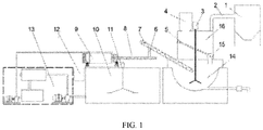
- Embodiment 1 The separating and melting system and method for a waste lead grid includes a dust remover 1, a flue gas duct 2, a lead-containing liquid agitator 3, a lead grid turnover box 4, a lead grid barrier plate 5, an ash discharging tube 6, an automatic ash acquiring machine 7, a lead ash transporter 8, a copper-made terminal separator 9, a lead mud tank 10, a lead mud agitator 11, a copper piece collection box 12, a circulating water treatment apparatus 13, a smelting apparatus 14, a spiral feeder 15, and a drying drum 16.
- the drying drum 16 is mounted on an upper end of the smelting apparatus 14.
- the dust remover 1 is connected to an upper end of the drying drum 16 by means of the flue gas duct 2.
- the lead grid turnover box 4 is connected to the upper end of the drying drum 16.
- the lead-containing liquid agitator 3 extends through the drying drum 16 into the smelting apparatus 14.
- the spiral feeder 15 is mounted on the smelting apparatus 14 and located in the drying drum 16. One end of the lead grid barrier plate 5 is placed on the spiral feeder 15, and the other end of the lead grid barrier plate 5 is placed on an inner wall of the drying drum 16.
- the automatic ash acquiring machine 7 is mounted on the smelting apparatus 14, a feed end of the automatic ash acquiring machine 7 is located in the smelting apparatus 14, and a discharge port of the automatic ash acquiring machine 7 is connected to a feed inlet of the lead ash transporter 8 by means of the ash discharging tube 6.
- a discharge port of the lead ash transporter 8 is located at the copper-made terminal separator 9.
- the copper-made terminal separator 9 is mounted on the lead mud tank 10.
- a circulating water flushing pipe 9-8 on the copper-made terminal separator 9 is connected to a clean water outlet end of the circulating water treatment apparatus 13 by means of a conduit, and a waste water inlet end of the circulating water treatment apparatus 13 is connected to a lower portion of the lead mud tank 10.
- the lead mud agitator 11 is further connected to the lead mud tank 10.
- the smelting apparatus 14 includes a pot cover 14-1, a smelting furnace 14-2, a smelting pot 14-3, a siphon lead release pipe 14-4, and a lead release valve 14-5.
- the smelting pot 14-3 is placed on the smelting furnace 14-2.
- the pot cover 14-1 is provided on a top of the smelting pot 14-3.
- the siphon lead release pipe 14-4 is provided at a bottom of the smelting pot 14-3.
- the siphon lead release pipe 14-4 outputs a lead-containing liquid by means of the lead release valve 14-5.
- the drying drum 16, the spiral feeder 15, and the automatic ash acquiring machine 7 are placed on the pot cover 14-1.
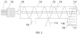
- the automatic ash acquiring machine includes a motor 7-1, a reducer 7-2, a coupling 7-3, a cylinder 7-4, a main shaft 7-5, a spiral blade 7-6, an ash inlet 7-7, an ash outlet 7-8, an ash collecting plate 7-9, leakage holes 7-10, a bottom bearing seat 7-11, and a bracket traveling wheel 7-12.
- a front end of the cylinder 7-4 is provided with the ash outlet 7-8, and a rear end of the cylinder is provided with the ash inlet 7-7.
- the main shaft 7-5 is mounted in the cylinder 7-4.
- the spiral blade 7-6 is mounted on the main shaft 7-5.
- the main shaft 7-5 runs through the cylinder 7-4.
- a rear end of the main shaft is connected to the bottom bearing seat 7-11, and a front end of the main shaft 7-5 is connected to the coupling 7-3.
- the coupling 7-3 is connected to the motor 7-1 by the reducer 7-2.
- the ash collecting plate 7-9 is connected to the cylinder 7-4 at a position of the ash inlet 7-7.
- Leakage holes 7-10 having a diameter of ⁇ 3-6 mm are evenly distributed on the ash collecting plate 7-9, allowing the lead-containing liquid to flow back into the smelting lead pot, so that the lead-containing liquid is fully separated from a lead ash.
- the bracket traveling wheel 7-12 is connected to a bottom surface of the cylinder 7-4.
- the bracket traveling wheel 7-12 is located on a wall of the cylinder 7-4 between the ash outlet 7-8 and the ash inlet 7-7. Wheels are disposed on bracket feet of the bracket traveling wheel 7-12, to facilitate the movement of the entire ash acquiring machine on the ground.
- the spiral feeder 15 is located at a lower end of the lead grid barrier plate 5 and has two ends arranged outside the drying drum 16.
- the spiral feeder is provided with a feeding port at an upper portion thereof and a discharging port at a lower portion thereof.
- the lead grid barrier plate 5 is an elliptical 10-20 mm thick high-temperature resistant steel plate, with all sides thereof connected to the inner wall of the drying drum 16.
- the lower end of the lead grid barrier plate 5 is connected to the spiral feeder 7, forming an angle of 30-60° with a surface of the smelting pot. Vent holes having a diameter of ⁇ 2-6 mm are evenly distributed on the lead grid barrier plate, to facilitate the transfer of flue gas waste heat to preheat the waste lead grid.
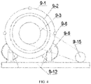
- the copper-made terminal separator 9 includes an outer cylinder 9-1, a rotary screen 9-2, a drive pulley 9-3, an ash inlet 9-4, a lead ash transporter 9-5, a supporting roller 9-6, a supporting roller bracket 9-7, the circulating water flushing pipe 9-8, a material deflector 9-9, a discharge port supporting roller track 9-10, a copper piece screen 9-11, a lead ash slurry outlet 9-12, a copper piece discharge port 9-13, a feeding port supporting roller track 9-14, and a motor 9-15.
- Two ends of the rotary screen 9-2 are each connected to a supporting roller track, i.e., are respectively connected to the discharge port supporting roller track 9-10 and the feeding port supporting roller track 9-14.
- the supporting roller track is a hollow ring in communication with an inside of the rotary screen.
- a corresponding supporting roller 9-6 is provided on the supporting roller track.
- the supporting roller 9-6 is mounted on the supporting roller bracket 9-7.
- One end of the discharge port supporting roller track 9-10 is connected to the copper piece screen 9-11.
- An end portion of the copper piece screen 9-11 is a copper piece discharging port 9-13.
- the drive pulley 9-3 is connected to one side of the feeding port supporting roller track 9-14.
- the drive pulley 9-3 is connected to the motor 9-15 by a belt.
- the lead ash transporter 9-5 runs through the ring of the feeding port supporting roller track and enters the rotary screen 9-2.
- the ash inlet 9-4 is provided at the other end of the lead ash transporter 9-5.
- the material deflector 9-2 is provided at an inner wall of the rotary screen 9-9.
- the outer cylinder 9-1 is provided outside the rotary screen 9-2.
- the lead ash slurry outlet 9-12 is provided at a bottom of the outer cylinder 9-1.
- the circulating water flushing pipe 9-8 is connected to the outer cylinder 9-1.
- the circulating water flushing pipe 9-8 sprays circulating water to the rotating rotary screen 9-2.
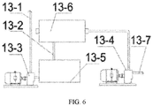
- the circulating water treatment apparatus includes a clean water output pipe 13-1, a filter pressing water return pipe 13-2, a clean water pump 13-3, a lead mud pump 13-4, a circulating water pool 13-5, a filter press 13-6, and a lead slurry input pipe 13-7.
- a water inlet end of the clean water pump 13-3 is connected to the circulating water pool 13-5.
- a water outlet end of the clean water pump 13-3 is connected to a circulating water inlet pipe 13-1.
- the filter press 13-6 is provided above the circulating water pool 13-5.
- An output end of the filter press 13-6 is connected to the circulating water pool 13-5 by the filter pressing water return pipe 13-2.
- An input end of the filter press 13-6 is connected to an output end of the lead mud pump 13-4 by a conduit, and an input end of the lead mud pump 13-4 is connected to the lower portion of the lead mud tank 10.
- the separating and melting method includes the following steps:
Landscapes
- Engineering & Computer Science (AREA)
- Chemical & Material Sciences (AREA)
- Manufacturing & Machinery (AREA)
- Materials Engineering (AREA)
- Organic Chemistry (AREA)
- Metallurgy (AREA)
- Mechanical Engineering (AREA)
- Environmental & Geological Engineering (AREA)
- General Life Sciences & Earth Sciences (AREA)
- Life Sciences & Earth Sciences (AREA)
- Geology (AREA)
- General Chemical & Material Sciences (AREA)
- Electrochemistry (AREA)
- Chemical Kinetics & Catalysis (AREA)
- Physics & Mathematics (AREA)
- Thermal Sciences (AREA)
- Manufacture And Refinement Of Metals (AREA)
- Processing Of Solid Wastes (AREA)
Applications Claiming Priority (2)
| Application Number | Priority Date | Filing Date | Title |
|---|---|---|---|
| CN201810396665.7A CN108342581B (zh) | 2018-04-28 | 2018-04-28 | 一种废铅酸蓄电池回收中废铅栅网的分离熔化系统及方法 |
| PCT/CN2019/082106 WO2019205941A1 (zh) | 2018-04-28 | 2019-04-10 | 一种废铅酸蓄电池回收中废铅栅网的分离熔化系统及方法 |
Publications (2)
| Publication Number | Publication Date |
|---|---|
| EP3770286A1 true EP3770286A1 (de) | 2021-01-27 |
| EP3770286A4 EP3770286A4 (de) | 2021-12-29 |
Family
ID=62955321
Family Applications (1)
| Application Number | Title | Priority Date | Filing Date |
|---|---|---|---|
| EP19793489.6A Withdrawn EP3770286A4 (de) | 2018-04-28 | 2019-04-10 | Verfahren und vorrichtung zum trennen und schmelzen von bleiabfallgittern beim recyceln von blei-säure-abfallakkumulator |
Country Status (5)
| Country | Link |
|---|---|
| US (1) | US11339456B2 (de) |
| EP (1) | EP3770286A4 (de) |
| CN (1) | CN108342581B (de) |
| AU (1) | AU2019260137B2 (de) |
| WO (1) | WO2019205941A1 (de) |
Cited By (2)
| Publication number | Priority date | Publication date | Assignee | Title |
|---|---|---|---|---|
| JP2022115016A (ja) * | 2021-01-27 | 2022-08-08 | 生態環境部華南環境科学研究所 | 廃棄鉛蓄電池資源の統合回収装置および方法 |
| CN114949891A (zh) * | 2022-06-12 | 2022-08-30 | 内蒙古溢多利生物科技有限公司 | 一种酶制剂恒温喷雾干燥系统 |
Families Citing this family (8)
| Publication number | Priority date | Publication date | Assignee | Title |
|---|---|---|---|---|
| CN108342581B (zh) * | 2018-04-28 | 2023-07-18 | 江苏新春兴再生资源有限责任公司 | 一种废铅酸蓄电池回收中废铅栅网的分离熔化系统及方法 |
| CN109750166A (zh) * | 2019-03-20 | 2019-05-14 | 河北港安环保科技有限公司 | 一种电池铜头分离装置 |
| CN109807317A (zh) * | 2019-03-20 | 2019-05-28 | 河北金宇晟再生资源利用有限公司 | 一种电解铅车间用粗铅除尘捞渣机 |
| CN112129100B (zh) * | 2020-09-21 | 2022-09-09 | 天能集团(濮阳)再生资源有限公司 | 一种废旧铅酸蓄电池熔炼装置及熔炼方法 |
| CN112853116B (zh) * | 2020-12-29 | 2023-04-07 | 安徽天畅金属材料有限公司 | 一种基于废旧铅酸蓄电池的含铅物质回收处理装置 |
| CN113174489A (zh) * | 2021-05-11 | 2021-07-27 | 天津市洪瑞昌泰节能科技股份有限公司 | 一种铅栅低温熔铸工艺 |
| CN113337732A (zh) * | 2021-06-30 | 2021-09-03 | 河南豫光冶金机械制造有限公司 | 一种粗铅火法精炼装置 |
| CN113737016B (zh) * | 2021-09-18 | 2022-11-11 | 安徽华铂再生资源科技有限公司 | 一种从锡酸钠溶液压滤固体物中冶炼粗锡的工艺 |
Family Cites Families (27)
| Publication number | Priority date | Publication date | Assignee | Title |
|---|---|---|---|---|
| US3734718A (en) * | 1971-12-15 | 1973-05-22 | Dow Chemical Co | Magnesium-magnesium chloride bath separation |
| US4098685A (en) * | 1977-01-06 | 1978-07-04 | Akerlow Industries, Inc. | Apparatus and method for separating lead battery materials |
| KR20040005770A (ko) * | 2003-12-17 | 2004-01-16 | 홍성호 | 폐배터리 재활용 장치 |
| CN2835238Y (zh) * | 2005-11-04 | 2006-11-08 | 唐山化工机械有限公司化工机械设计研究所 | 前排式回转化灰机 |
| JP5090027B2 (ja) | 2007-03-15 | 2012-12-05 | 細倉金属鉱業株式会社 | 切断装置 |
| CN101414698A (zh) * | 2008-12-10 | 2009-04-22 | 河南豫光金铅股份有限公司 | 废旧蓄电池铅栅的熔融及配合金的装置及工艺 |
| CN201324831Y (zh) | 2008-12-10 | 2009-10-14 | 河南豫光金铅股份有限公司 | 用于处理铅栅的熔铸装置 |
| RU98192U1 (ru) * | 2009-12-10 | 2010-10-10 | Общество с ограниченной ответственностью Научно-технологический центр "Аурум" | Линия переработки шламов аккумуляторного лома |
| CN101979165B (zh) * | 2010-09-26 | 2013-02-27 | 杨春明 | 废铅酸蓄电池破碎分选机及分选方法 |
| CN102055045B (zh) * | 2010-12-10 | 2012-10-24 | 尚诚德 | 一种废旧铅酸蓄电池回收处理方法 |
| CN103014348B (zh) * | 2012-12-14 | 2015-01-07 | 河南豫光金铅股份有限公司 | 对废旧铅酸蓄电池分选的板栅进行连续处理的装置及工艺 |
| CN104183883B (zh) * | 2013-07-22 | 2017-04-19 | 天能电池(芜湖)有限公司 | 一种蓄电池端子生产设备铅渣回收利用装置 |
| CN203599041U (zh) * | 2013-12-05 | 2014-05-21 | 魏兴虎 | 一种蓄电池铅膏分离设备 |
| CN103667725A (zh) * | 2013-12-31 | 2014-03-26 | 河南豫光金铅股份有限公司 | 废旧铅酸蓄电池铅膏底吹熔炼一步炼铅工艺及装置 |
| CN203999760U (zh) * | 2014-06-18 | 2014-12-10 | 湖南鸿飞机械有限公司 | 粗铅脱铜锅环保捞渣装置 |
| CN104087756A (zh) | 2014-07-28 | 2014-10-08 | 扬州市华翔有色金属有限公司 | 一种再生铅氧化还原冶炼方法 |
| CN205508980U (zh) | 2016-03-22 | 2016-08-24 | 安徽华铂再生资源科技有限公司 | 电池极柱铜头分离装置 |
| CN105950868A (zh) * | 2016-05-27 | 2016-09-21 | 广东新生环保科技股份有限公司 | 废旧铅酸蓄电池的铜铅分离工艺 |
| CN106000557B (zh) * | 2016-06-18 | 2018-10-16 | 江苏新春兴再生资源有限责任公司 | 一种处理废铅酸蓄电池细铅栅的铅针、铅泥分离机 |
| CN106252743B (zh) | 2016-08-25 | 2020-02-04 | 安徽华铂再生资源科技有限公司 | 废铅酸蓄电池铅零件、铅栅低温脱渣和铜极柱分离回收工艺 |
| CN206015041U (zh) * | 2016-09-28 | 2017-03-15 | 江苏新春兴再生资源有限责任公司 | 一种布料式热风烘干的再生铅熔炼炉螺旋加料装置 |
| CN107309158A (zh) * | 2017-07-24 | 2017-11-03 | 共享铸钢有限公司 | 铸钢件抛丸用钢丸回收装置 |
| CN108342581B (zh) | 2018-04-28 | 2023-07-18 | 江苏新春兴再生资源有限责任公司 | 一种废铅酸蓄电池回收中废铅栅网的分离熔化系统及方法 |
| CN108620229B (zh) | 2018-04-28 | 2024-03-15 | 江苏新春兴再生资源有限责任公司 | 一种用于从铅灰中分离铜件端子的分离装置及方法 |
| CN208121173U (zh) | 2018-04-28 | 2018-11-20 | 江苏新春兴再生资源有限责任公司 | 连续干燥熔化自动捞灰的一体化处理回收废铅栅网装置 |
| CN108330292A (zh) | 2018-04-28 | 2018-07-27 | 江苏新春兴再生资源有限责任公司 | 连续干燥熔化自动捞灰的一体化处理废铅栅网装置及方法 |
| CN208121171U (zh) * | 2018-04-28 | 2018-11-20 | 江苏新春兴再生资源有限责任公司 | 一种废铅酸蓄电池回收中废铅栅网的分离熔化系统 |
-
2018
- 2018-04-28 CN CN201810396665.7A patent/CN108342581B/zh active Active
-
2019
- 2019-04-10 AU AU2019260137A patent/AU2019260137B2/en not_active Ceased
- 2019-04-10 EP EP19793489.6A patent/EP3770286A4/de not_active Withdrawn
- 2019-04-10 WO PCT/CN2019/082106 patent/WO2019205941A1/zh not_active Ceased
- 2019-04-10 US US17/050,841 patent/US11339456B2/en active Active
Cited By (2)
| Publication number | Priority date | Publication date | Assignee | Title |
|---|---|---|---|---|
| JP2022115016A (ja) * | 2021-01-27 | 2022-08-08 | 生態環境部華南環境科学研究所 | 廃棄鉛蓄電池資源の統合回収装置および方法 |
| CN114949891A (zh) * | 2022-06-12 | 2022-08-30 | 内蒙古溢多利生物科技有限公司 | 一种酶制剂恒温喷雾干燥系统 |
Also Published As
| Publication number | Publication date |
|---|---|
| EP3770286A4 (de) | 2021-12-29 |
| US20210230713A1 (en) | 2021-07-29 |
| WO2019205941A1 (zh) | 2019-10-31 |
| CN108342581B (zh) | 2023-07-18 |
| US11339456B2 (en) | 2022-05-24 |
| AU2019260137A1 (en) | 2020-11-19 |
| CN108342581A (zh) | 2018-07-31 |
| AU2019260137B2 (en) | 2021-11-25 |
Similar Documents
| Publication | Publication Date | Title |
|---|---|---|
| AU2019260137B2 (en) | Separating and melting system and method for waste lead grid in waste lead acid storage battery recycling | |
| CN113731607B (zh) | 一种废旧锂电池破碎系统及其工艺 | |
| CN113354129A (zh) | 一种自动化数控机床排屑装置 | |
| CN103045777A (zh) | 一种含铁钢渣的干法处理工艺 | |
| CN101414698A (zh) | 废旧蓄电池铅栅的熔融及配合金的装置及工艺 | |
| CN108330292A (zh) | 连续干燥熔化自动捞灰的一体化处理废铅栅网装置及方法 | |
| CN107142380B (zh) | 再生铅低温连续熔炼工艺 | |
| CN102623772A (zh) | 废旧铅蓄电池综合再处理装置 | |
| CN216736200U (zh) | 一种铅电解残极和析出铅的输送与加锅装置 | |
| CN201324831Y (zh) | 用于处理铅栅的熔铸装置 | |
| CN208121173U (zh) | 连续干燥熔化自动捞灰的一体化处理回收废铅栅网装置 | |
| CN212664374U (zh) | 一种废铁渣回收装置 | |
| CN208121171U (zh) | 一种废铅酸蓄电池回收中废铅栅网的分离熔化系统 | |
| CN201684884U (zh) | 铸造旧砂、炉渣回收处理设备 | |
| CN209349045U (zh) | 一种破碎后锂电池分选设备 | |
| CN103337440B (zh) | 一种废荧光灯材料分离分选自动生产装置及方法 | |
| CN106238441A (zh) | 去除生活垃圾有机废弃物中重金属的工艺及其电解装置 | |
| CN207204833U (zh) | 工业渣盐的分选、粉碎及输送装置 | |
| CN202454693U (zh) | 废旧铅蓄电池综合再处理装置 | |
| CN113846220B (zh) | 一种废铝回收自动化加工设备 | |
| CN216226112U (zh) | 碳化电池回收处理线 | |
| CN117358348A (zh) | 铝电解质炭渣资源化利用方法 | |
| CN215429583U (zh) | 粉煤灰资源化利用系统 | |
| CN204816014U (zh) | 一种预焙阳极生胚生产排放的沥青烟净化器 | |
| CN113617798A (zh) | 一种有机固废焚烧飞灰无害化处理系统 |
Legal Events
| Date | Code | Title | Description |
|---|---|---|---|
| STAA | Information on the status of an ep patent application or granted ep patent |
Free format text: STATUS: THE INTERNATIONAL PUBLICATION HAS BEEN MADE |
|
| PUAI | Public reference made under article 153(3) epc to a published international application that has entered the european phase |
Free format text: ORIGINAL CODE: 0009012 |
|
| STAA | Information on the status of an ep patent application or granted ep patent |
Free format text: STATUS: REQUEST FOR EXAMINATION WAS MADE |
|
| 17P | Request for examination filed |
Effective date: 20201020 |
|
| AK | Designated contracting states |
Kind code of ref document: A1 Designated state(s): AL AT BE BG CH CY CZ DE DK EE ES FI FR GB GR HR HU IE IS IT LI LT LU LV MC MK MT NL NO PL PT RO RS SE SI SK SM TR |
|
| AX | Request for extension of the european patent |
Extension state: BA ME |
|
| DAV | Request for validation of the european patent (deleted) | ||
| DAX | Request for extension of the european patent (deleted) | ||
| REG | Reference to a national code |
Ref country code: DE Ref legal event code: R079 Free format text: PREVIOUS MAIN CLASS: C22B0007000000 Ipc: C22B0013020000 |
|
| A4 | Supplementary search report drawn up and despatched |
Effective date: 20211125 |
|
| RIC1 | Information provided on ipc code assigned before grant |
Ipc: B09B 3/00 20060101ALI20211119BHEP Ipc: H01M 10/54 20060101ALI20211119BHEP Ipc: C22B 9/10 20060101ALI20211119BHEP Ipc: C22B 7/00 20060101ALI20211119BHEP Ipc: C22B 7/04 20060101ALI20211119BHEP Ipc: C22B 13/02 20060101AFI20211119BHEP |
|
| STAA | Information on the status of an ep patent application or granted ep patent |
Free format text: STATUS: THE APPLICATION IS DEEMED TO BE WITHDRAWN |
|
| 18D | Application deemed to be withdrawn |
Effective date: 20231101 |