EP3769918B1 - Artikeltransfervorrichtung - Google Patents
Artikeltransfervorrichtung Download PDFInfo
- Publication number
- EP3769918B1 EP3769918B1 EP19770272.3A EP19770272A EP3769918B1 EP 3769918 B1 EP3769918 B1 EP 3769918B1 EP 19770272 A EP19770272 A EP 19770272A EP 3769918 B1 EP3769918 B1 EP 3769918B1
- Authority
- EP
- European Patent Office
- Prior art keywords
- gripping unit
- gripping
- unit
- article
- robot hand
- Prior art date
- Legal status (The legal status is an assumption and is not a legal conclusion. Google has not performed a legal analysis and makes no representation as to the accuracy of the status listed.)
- Active
Links
Images


Classifications
-
- B—PERFORMING OPERATIONS; TRANSPORTING
- B25—HAND TOOLS; PORTABLE POWER-DRIVEN TOOLS; MANIPULATORS
- B25J—MANIPULATORS; CHAMBERS PROVIDED WITH MANIPULATION DEVICES
- B25J9/00—Programme-controlled manipulators
- B25J9/16—Programme controls
- B25J9/1612—Programme controls characterised by the hand, wrist, grip control
-
- B—PERFORMING OPERATIONS; TRANSPORTING
- B25—HAND TOOLS; PORTABLE POWER-DRIVEN TOOLS; MANIPULATORS
- B25J—MANIPULATORS; CHAMBERS PROVIDED WITH MANIPULATION DEVICES
- B25J13/00—Controls for manipulators
- B25J13/02—Hand grip control means
-
- B—PERFORMING OPERATIONS; TRANSPORTING
- B25—HAND TOOLS; PORTABLE POWER-DRIVEN TOOLS; MANIPULATORS
- B25J—MANIPULATORS; CHAMBERS PROVIDED WITH MANIPULATION DEVICES
- B25J11/00—Manipulators not otherwise provided for
- B25J11/0045—Manipulators used in the food industry
-
- B—PERFORMING OPERATIONS; TRANSPORTING
- B25—HAND TOOLS; PORTABLE POWER-DRIVEN TOOLS; MANIPULATORS
- B25J—MANIPULATORS; CHAMBERS PROVIDED WITH MANIPULATION DEVICES
- B25J15/00—Gripping heads and other end effectors
- B25J15/08—Gripping heads and other end effectors having finger members
- B25J15/10—Gripping heads and other end effectors having finger members with three or more finger members
-
- B—PERFORMING OPERATIONS; TRANSPORTING
- B65—CONVEYING; PACKING; STORING; HANDLING THIN OR FILAMENTARY MATERIAL
- B65G—TRANSPORT OR STORAGE DEVICES, e.g. CONVEYORS FOR LOADING OR TIPPING, SHOP CONVEYOR SYSTEMS OR PNEUMATIC TUBE CONVEYORS
- B65G47/00—Article or material-handling devices associated with conveyors; Methods employing such devices
- B65G47/74—Feeding, transfer, or discharging devices of particular kinds or types
- B65G47/90—Devices for picking-up and depositing articles or materials
- B65G47/905—Control arrangements
-
- B—PERFORMING OPERATIONS; TRANSPORTING
- B25—HAND TOOLS; PORTABLE POWER-DRIVEN TOOLS; MANIPULATORS
- B25J—MANIPULATORS; CHAMBERS PROVIDED WITH MANIPULATION DEVICES
- B25J9/00—Programme-controlled manipulators
- B25J9/16—Programme controls
- B25J9/1679—Programme controls characterised by the tasks executed
-
- G—PHYSICS
- G05—CONTROLLING; REGULATING
- G05B—CONTROL OR REGULATING SYSTEMS IN GENERAL; FUNCTIONAL ELEMENTS OF SUCH SYSTEMS; MONITORING OR TESTING ARRANGEMENTS FOR SUCH SYSTEMS OR ELEMENTS
- G05B2219/00—Program-control systems
- G05B2219/30—Nc systems
- G05B2219/39—Robotics, robotics to robotics hand
- G05B2219/39514—Stability of grasped objects
-
- G—PHYSICS
- G05—CONTROLLING; REGULATING
- G05B—CONTROL OR REGULATING SYSTEMS IN GENERAL; FUNCTIONAL ELEMENTS OF SUCH SYSTEMS; MONITORING OR TESTING ARRANGEMENTS FOR SUCH SYSTEMS OR ELEMENTS
- G05B2219/00—Program-control systems
- G05B2219/30—Nc systems
- G05B2219/45—Nc applications
- G05B2219/45111—Meal, food assistance
Definitions
- the present disclosure relates to an article transfer device.
- An article transfer device grips an article such as food accommodated in a container with a robot hand and transfers the article at the gripping part to another container or the like.
- a robot hand used for such article transfer devices is described in, for example, Patent Literature 1.
- Patent Literature 1 Japanese Unexamined Patent Publication No. 2017-47481 JP-A-2015085439 provides a technique for gripping a soft object to be held.
- a gripping device comprises a plurality of holding sections. Each of the plurality of holding sections comprises a film-like member having flexibility.
- the plurality of holding sections is configured so as to be able to grip a plurality of types of objects to be gripped which is the plurality of types of objects to be gripped having an index of softness ranging from 3 mm/gf to 10 mm/gf and has the index of softness different from one another.
- JP-A-2014042965 describes a method for transferring a workpiece including the steps of: bringing a plurality of contact parts provided in a workpiece holding device mounted in a robot arm into contact with a plurality of contact portions of the workpiece and pressing at least one of the plurality of contact parts onto the workpiece to hold the workpiece; operating the robot arm to transfer the workpiece; tilting the workpiece in the middle of the transfer of the workpiece to change the posture of the workpiece; and releasing the holding of the workpiece transferred to a workpiece receive for receiving the workpiece to hand over the workpiece to the workpiece receiver.
- an object of the present disclosure is to provide an article transfer device capable of stably gripping an article.
- An article transfer device a robot hand having a gripping unit gripping an article and transferring the article gripped by the gripping unit to a transfer destination;
- the article transfer device performs the opening-closing operation of the gripping unit at least once with the gripping unit inserted in the article region where the plurality of articles are disposed and then grips the article by closing the gripping unit.
- the article transfer device temporarily collects the predetermined amount of the article to be gripped by the opening-closing operation of the gripping unit and then grips the collected article. In this manner, the article that is collected is gripped by the gripping unit, and thus the article transfer device is capable of stably gripping the article by means of the gripping unit.
- the control unit also controls the operation of the robot hand such that the gripping unit rotates by a predetermined first angle around an axis along a direction of insertion of the gripping unit during the temporary closing, the subsequent opening, and subsequent reclosing of the gripping unit at the position of the gripping unit at the time when the gripping unit is inserted in the article region.
- the article transfer device is capable of collecting or gripping the article to be gripped by abutting against the predetermined amount of the article to be gripped from a direction different from the direction at the time of the previous closing of the gripping unit. In this manner, the gripping unit collects or grips the article from different directions, and thus the article transfer device is capable of further collecting and more stably gripping the article.
- an article transfer device comprises a robot hand having a gripping unit gripping an article and transferring the article gripped by the gripping unit to a transfer destination; and a control unit controlling operation of the robot hand, characterized in that the control unit is adapted to insert the gripping unit into an article region where a plurality of the articles are disposed, grip a predetermined amount of the articles, and transfer the gripped predetermined amount of the articles to the transfer destination,
- control unit controls the operation of the robot hand such that the gripping unit rotates by a predetermined second angle around an axis along a direction of insertion of the gripping unit when the gripping unit remains closed at the position of the gripping unit at the time when the gripping unit is inserted in the article region.
- the article transfer device rotates the gripping unit in a state where the article as a part of the plurality of articles is gripped, and thus it is possible to separate the article gripped by the gripping unit from the surrounding article (article that is not to be gripped).
- the article transfer device is capable of stably gripping the predetermined amount of the article to be gripped.
- the control unit may control the operation of the robot hand such that an opening amount at the time when the gripping unit is opened after the gripping unit is temporarily closed with the gripping unit inserted in the article region is smaller than the opening amount of the gripping unit at the time when the gripping unit is inserted into the article region.
- the article transfer device is capable of shortening the time for the operation of opening the gripping unit and quickly gripping the article.
- the control unit may control the operation of the robot hand so as to continuously execute a plurality of times the serial operation of closing the gripping unit, gripping the predetermined amount of the article, and transferring the article to the transfer destination after executing at least once the opening-closing operation of inserting the gripping unit into the article region, temporarily closing the gripping unit, and then opening the gripping unit.
- the article transfer device is capable of sequentially transferring the predetermined amount of the article from the plurality of articles in the article region to the transfer destination.
- An article can be stably gripped according to the article transfer device of the present disclosure.
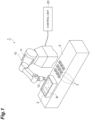
- a food material group B which is an aggregate of a plurality of food materials (articles) B1 (see FIG. 3 ), is accommodated (disposed) in a tray 2.
- An article transfer device 1 takes out a predetermined amount of the food material B1 from the inside of the tray 2 and transfers the food material B1 to a container 3 such as a lunch case.
- the article transfer device 1 includes a robot hand 10 and a control unit 20.
- the robot hand 10 is provided near the container 3 and the tray 2 placed on a workbench 5.
- a plurality of the containers 3 are disposed on the workbench 5.
- Each of the tray 2 and the container 3 is a box body having an open upper portion.
- the robot hand 10 takes out a target gripping amount (predetermined amount) of the food material B1 from the tray 2 and sequentially transfers the food material B1 to the plurality of containers 3.
- the robot hand 10 includes an arm portion 11 and a gripping unit 12.
- the gripping unit 12 is attached to the tip portion of the arm portion 11.
- the arm portion 11 has a plurality of joints.
- the arm portion 11 is capable of moving the gripping unit 12 to a desired position by turning and bending the joint.
- the operation of the arm portion 11 is controlled by the control unit 20.
- the arm portion 11 operates based on a control signal output from the control unit 20.
- the gripping unit 12 grips a part of the food material B1 from the food material group B.
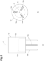
- the gripping unit 12 includes a main body portion 12a, three gripping members 12b, and a drive unit 12c as illustrated in FIGS. 2(a) and 2(b) .
- the main body portion 12a is a housing having a central axis C.
- the main body portion 12a has, for example, a columnar outer shape.
- the main body portion 12a is formed of, for example, metal.
- the main body portion 12a is attached to the tip portion of the arm portion 11.
- the gripping member 12b is a rod-shaped member.
- the gripping member 12b is formed of, for example, resin, metal, or the like.
- the gripping member 12b is attached to the main body portion 12a so as to protrude downward from the main body portion 12a.
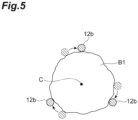
- Each of the three gripping members 12b is disposed on a virtual circle about the central axis C.
- the three gripping members 12b are disposed at equal intervals (120° intervals) in the circumferential direction of the virtual circle.
- the gripping member 12b is movably provided on the main body portion 12a. Specifically, the gripping member 12b moves by being driven by the drive unit 12c.
- the drive unit 12c moves the gripping member 12b in a direction toward the central axis C and a direction away from the central axis C.
- the drive unit 12c moves the three gripping members 12b in synchronization. As a result, the three gripping members 12b move in a direction toward each other and a direction away from each other.
- the drive unit 12c is configured to include, for example, a motor and a link mechanism.
- the operation of the drive unit 12c is controlled by the control unit 20.
- the drive unit 12c operates based on a control signal output from the control unit 20.
- the gripping member 12b of the gripping unit 12 is inserted into the food material group B by the arm portion 11 moving the gripping unit 12 from the upper side to the lower side along the vertical direction.
- the direction of insertion of the gripping unit 12 into the food material group B coincides with the vertical direction.
- the inclination of the gripping unit 12 is adjusted by the arm portion 11 such that the direction of extension of the central axis C coincides with the vertical direction when the gripping unit 12 is inserted into the food material group B.
- the drive unit 12c moves the three gripping members 12b in a direction toward each other.
- the gripping unit 12 grips the food material B1 positioned inside an inscribed circle R (see FIG. 2(b) ) inscribed in the three gripping members 12b.
- the gripping amount of the food material B1 gripped by the gripping unit 12 is determined by the insertion depth of the gripping member 12b inserted into the food material group B and the opening amount of the three gripping members 12b at the time when the gripping member 12b is inserted into the food material group B.
- the gripping unit 12 is capable of gripping an increasing amount of the food material B1 as the insertion depth of the gripping member 12b into the food material group B increases.
- the gripping unit 12 is capable of gripping an increasing amount of the food material B1 as the opening amount of the three gripping members 12b increases.
- the robot hand 10 grips a part of the food material B1 from the food material group B by inserting the gripping member 12b of the gripping unit 12 into the food material group B in the tray 2. Subsequently, the robot hand 10 moves the gripping unit 12 to above the container 3, which is a transfer destination, by operating the arm portion 11. Then, the robot hand 10 is capable of transferring the gripped food material B1 to the container 3 as a transfer destination by releasing the food material B1 from the gripping unit 12.
- the control unit 20 controls the operation of the robot hand 10.
- the control unit 20 may be accommodated in the robot hand 10 or may be provided outside the robot hand 10.
- the control unit 20 is an electronic control unit having a central processing unit (CPU), a read only memory (ROM), a random access memory (RAM), and the like.
- the control unit 20 controls the operation of the robot hand 10 by outputting a control signal to the robot hand 10.
- control unit 20 controls the operation of the robot hand 10 such that a predetermined amount of the food material B 1 is gripped by the gripping member 12b being inserted into the food material group B in the tray 2 (article region where the food material B 1 is placed) and the gripped food material B1 is transferred to the container 3 as a transfer destination.
- control unit 20 controls the insertion depth and the opening amount at the time when the gripping member 12b is inserted into the food material group B such that a predetermined amount of the food material B1 is gripped by the gripping unit 12 as described above.
- the control unit 20 executes opening-closing operation for opening the gripping member 12b after temporarily closing the three gripping members 12b at the position of the gripping unit 12 (main body portion 12a) at the time when the gripping member 12b is inserted in the food material group B at least once.
- the opening-closing operation is to temporarily close the three gripping members 12b and then open the gripping member 12b. Then, after the opening-closing operation of the gripping member 12b, the control unit 20 controls the operation of the robot hand 10 such that the gripping member 12b is closed and a predetermined amount of the food material B 1 is gripped.
- control unit 20 determines the insertion depth and the opening amount at a time when the gripping member 12b is inserted into the food material group B such that a predetermined amount of the food material B1 can be gripped.
- the control unit 20 controls the operation of the gripping unit 12 such that the determined opening amount of the gripping member 12b is reached.
- the control unit 20 controls the operation of the robot hand 10 such that the gripping member 12b is inserted by the determined insertion depth into the food material group B.
- the control unit 20 controls the operation of the gripping unit 12 so as to temporarily close the three gripping members 12b as illustrated in FIG. 4(b) .
- a predetermined amount of the food material B1 positioned inside the three gripping members 12b is separated from the surrounding food material B 1 and collected together.
- the control unit 20 controls the operation of the gripping unit 12 such that the gripping member 12b is opened again.
- control unit 20 controls the operation of the gripping unit 12 such that the opening amount at a time when the gripping member 12b is opened after the gripping member 12b is temporarily closed with the gripping member 12b inserted in the food material group B is smaller than the opening amount of the gripping member 12b at a time when the gripping member 12b is inserted into the food material group B.
- control unit 20 controls the operation of the gripping unit 12 such that the opening amount at a time when the gripping member 12b is reopened as illustrated in FIG. 4(c) is smaller than the opening amount of the gripping member 12b at a time when the gripping member 12b is inserted into the food material group B as illustrated in FIG. 4(a) .
- a length L (opening amount) from the central axis C to the gripping member 12b is shorter than the length L that is illustrated in FIG. 4(a) .
- the control unit 20 causes the gripping unit 12 to execute the opening-closing operation for opening the gripping member 12b after temporarily closing the three gripping members 12b as illustrated in FIGS. 4(b) and 4(c) at least once.
- the opening-closing operation for opening the gripping member 12b after temporarily closing the gripping member 12b as illustrated in FIGS. 4(b) and 4(c) will be referred to as "preliminary operation".
- the control unit 20 causes the gripping unit 12 to execute the preliminary operation illustrated in FIGS. 4(b) and 4(c) at least once. In other words, the gripping unit 12 collects the food material B1 by the preliminary operation.
- the control unit 20 controls the gripping unit 12 such that the gripping member 12b is closed and the food material B1 is gripped as illustrated in FIG. 4(d) . Subsequently, the control unit 20 controls the operation of the robot hand 10 such that the gripped food material B1 is transferred to the container 3 as a transfer destination.
- the operation of closing the gripping member 12b and gripping the food material B1 in order to transfer the food material B1 to the transfer destination as illustrated in FIG. 4(d) will be referred to as "gripping operation".
- the control unit 20 controls the operation of the robot hand 10 such that the gripping unit 12 rotates by a predetermined first angle around the central axis C (around an axis along the direction of insertion of the gripping unit 12) during the temporary closing, subsequent opening, and subsequent reclosing of the gripping member 12b.
- the control unit 20 changes the position where the gripping member 12b grips the food material B1 when the gripping member 12b is closed by rotating the gripping unit 12 by the first angle.
- control unit 20 may rotate the gripping unit 12 by the first angle each time the gripping member 12b is closed during the preliminary operation in a case where the preliminary operation illustrated in FIGS. 4(b) and 4(c) is executed a plurality of times.
- control unit 20 may rotate the gripping unit 12 by the first angle between the closing of the gripping member 12b in the preliminary operation and the closing of the gripping member 12b in the gripping operation.
- the control unit 20 controls the operation of the robot hand 10 such that the gripping unit 12 rotates by a predetermined second angle around the central axis C when the gripping member 12b remains closed. In other words, the control unit 20 rotates the entire gripping unit 12 by the second angle with the gripping member 12b closed.
- control unit 20 may rotate the gripping unit 12 by the second angle when the gripping member 12b remains closed in the preliminary operation as illustrated in FIG. 4(b) .
- control unit 20 may rotate the gripping unit 12 by the second angle when the gripping member 12b remains closed in the gripping operation.
- the second angle may be equal to or different from the first angle.
- the food material B1 is sequentially transferred to the plurality of containers 3 by the control unit 20 controlling the operation of the robot hand 10 such that the serial operation described with reference to FIGS. 4(a) to 4(d) is repeatedly executed.
- the control unit 20 controls the operation of the robot hand 10 so as to continuously execute a plurality of times the serial operation in which the gripping member 12b is closed and a predetermined amount of the food material B1 is gripped after the opening-closing operation (preliminary operation) in which the gripping member 12b is inserted into the food material group B, temporarily closed, and then opened is executed at least once.
- the article transfer device 1 performs the opening-closing operation (preliminary operation) of the gripping member 12b at least once with the gripping member 12b inserted in the food material group B and then grips the food material B1 by closing the gripping member 12b.
- the article transfer device 1 temporarily collects a predetermined amount of the food material B1 to be gripped by the opening-closing operation of the gripping member 12b and then grips the collected food material B1.
- the food material B1 that is collected is gripped by the gripping member 12b, and thus the article transfer device 1 is capable of stably gripping the food material B 1 by means of the gripping unit 12.
- the article transfer device 1 rotates the gripping unit 12 by the first angle around the central axis C during the temporary closing, subsequent opening, and subsequent reclosing of the gripping member 12b.
- the article transfer device 1 is capable of collecting or gripping the food material B1 by abutting of the gripping member 12b against a predetermined amount of the food material B1 to be gripped from a direction different from the direction at the time of the previous closing.
- the gripping member 12b collects or grips the food material B1 from different directions, and thus the article transfer device 1 is capable of further collecting and more stably gripping the food material B1.
- the article transfer device 1 rotates the gripping unit 12 by the second angle around the central axis C. In this manner, the article transfer device 1 rotates the gripping unit 12 in a state where the food material B1 as a part of the food material group B is gripped, and thus it is possible to separate the food material B1 gripped by the gripping member 12b from the surrounding food material B1 (food material B1 that is not to be gripped). As a result, the article transfer device 1 is capable of stably gripping a predetermined amount of the food material B1 to be gripped.
- the control unit 20 controls the operation of the gripping unit 12 such that the opening amount at a time when the gripping member 12b is opened after the gripping member 12b is temporarily closed with the gripping member 12b inserted in the food material group B is smaller than the opening amount of the gripping member 12b at a time when the gripping member 12b is inserted into the food material group B.
- the article transfer device 1 is capable of shortening the time for the operation of opening the gripping member 12b and quickly gripping the food material B1.
- the article transfer device 1 is capable of sequentially transferring a predetermined amount of the food material B1 from the food material group B to the plurality of containers 3 as a transfer destination.
- the present disclosure is not limited to the above embodiment.
- a form in which the gripping unit 12 has the three gripping members 12b has been described as an example in the above-described embodiment.
- the gripping unit 12 may have at least two gripping members.
- the gripping unit 12 may have any configuration insofar as the food material B1 is gripped by means of the configuration.
- the article transfer device 1 grips the food material B1 in the tray 2 and transfers the food material B1 to the container 3.
- the article transfer device 1 is capable of transferring various articles other than the food material B1 as transfer targets.
- the article transfer device 1 is not limited to transferring the food material B1 from the tray 2 to the container 3 and may be used for various purposes.
- the robot hand 10 is not limited to the configuration in which the gripping unit 12 is moved in both the horizontal direction and the vertical direction.
- the arm portion 11 of the robot hand 10 may be configured to move the gripping unit 12 only in the vertical direction and rotate the gripping unit 12 around an axis along the vertical direction.
- the article transfer device 1 includes a transport device alternately transporting the tray 2 that accommodates the food material group B and the container 3 that is empty to a position below the gripping unit 12.
- the robot hand 10 lowers the gripping unit 12 toward the tray 2 transported to the position below the gripping unit 12, grips the food material B1, and raises the gripping unit 12.
- the robot hand 10 is capable of transferring the food material B1 by lowering the gripping unit 12 toward the empty container 3 transported to the position below the gripping unit 12 and dropping the food material B1 into the container 3.
- a force (torque of the drive unit 12c) at a time when the gripping member 12b is closed and the food material B1 is gripped may be preset in the gripping unit 12.
- the gripping unit 12 moves the gripping member 12b to a position where the gripping member 12b can be closed by the preset force.
- the gripping unit 12 may stop the operation of closing the gripping member 12b before the gripping member 12b reaches a target closing position depending on the gripping state of the food material B1.
- the gripping unit 12 is capable of suppressing damage to the food material B1 when the gripping member 12b is closed and the food material B1 is gripped.
Landscapes
- Engineering & Computer Science (AREA)
- Mechanical Engineering (AREA)
- Robotics (AREA)
- Health & Medical Sciences (AREA)
- General Health & Medical Sciences (AREA)
- Orthopedic Medicine & Surgery (AREA)
- Life Sciences & Earth Sciences (AREA)
- Food Science & Technology (AREA)
- Manipulator (AREA)
- Specific Conveyance Elements (AREA)
Claims (7)
- Artikeltransfervorrichtung (1), umfassend:eine Roboterhand (10) mit einer Greifeinheit (12), die einen Artikel ergreift und den von der Greifeinheit gegriffenen Artikel zu einem Transferziel (3) transferiert; undeine Steuereinheit (20), die den Betrieb der Roboterhand (10) steuert, wobei die Steuereinheit dazu ausgebildet ist, die Greifeinheit (12) in einen Artikelbereich einzuführen, in dem eine Vielzahl der Artikel angeordnet sind, dadurch gekennzeichnet, dass die Steuereinheit dazu konfiguriert ist, die Greifeinheit so zu steuern, dass sie eine vorgegebene Menge der Artikel ergreift und die gegriffene vorgegebene Menge der Artikel zum Transferziel transferiert,dass die Steuereinheit (20) dazu ausgebildet ist, den Betrieb der Roboterhand (10) so zu steuern, dass die Greifeinheit (12) geschlossen wird und die vorgegebene Menge der Artikel ergriffen wird, nachdem ein Öffnungs-Schließvorgang zum Öffnen der Greifeinheit nach dem vorübergehenden Schließen der Greifeinheit mindestens einmal an einer Position der Greifeinheit zu einem Zeitpunkt ausgeführt wird, wenn die Greifeinheit in den Artikelbereich eingeführt ist, und dass die Steuereinheit (20) dazu ausgebildet ist, den Betrieb der Roboterhand (10) so zu steuern, dass die Greifeinheit (12) während des vorübergehenden Schließens, des anschließenden Öffnens und des anschließenden erneuten Schließens der Greifeinheit an der Position der Greifeinheit zu dem Zeitpunkt, wenn die Greifeinheit in den Artikelbereich eingeführt wird, um einen vorgegebenen ersten Winkel um eine Achse entlang einer Einführrichtung der Greifeinheit rotiert.
- Artikeltransfervorrichtung (1), umfassend:eine Roboterhand (10) mit einer Greifeinheit (12), die einen Artikel ergreift und den von der Greifeinheit gegriffenen Artikel zu einem Transferziel (3) transferiert; undeine Steuereinheit (20), die den Betrieb der Roboterhand (10) steuert, wobei die Steuereinheit dazu ausgebildet ist, die Greifeinheit (12) in einen Artikelbereich einzuführen, in dem eine Vielzahl der Artikel angeordnet sind, dadurch gekennzeichnet, dass die Steuereinheit dazu konfiguriert ist, die Greifeinheit so zu steuern, dass sie eine vorgegebene Menge der Artikel ergreift und die gegriffene vorgegebene Menge der Artikel zum Transferziel transferiert, dass die Steuereinheit (20) dazu ausgebildet ist, den Betrieb der Roboterhand (10) so zu steuern, dass die Greifeinheit (12) geschlossen wird und die vorgegebene Menge der Artikel ergriffen wird, nachdem ein Öffnungs-Schließvorgang zum Öffnen der Greifeinheit nach dem vorübergehenden Schließen der Greifeinheit mindestens einmal an einer Position der Greifeinheit zu einem Zeitpunkt ausgeführt wird, wenn die Greifeinheit in den Artikelbereich eingeführt wird, und dass die Steuereinheit (20) dazu ausgebildet ist, den Betrieb der Roboterhand (10) so zu steuern, dass die Greifeinheit (12) um einen vorgegebenen zweiten Winkel um eine Achse entlang einer Einführrichtung der Greifeinheit rotiert, wenn die Greifeinheit an der Position der Greifeinheit geschlossen bleibt, zu dem Zeitpunkt, an dem die Greifeinheit in den Artikelbereich eingeführt wird.
- Artikeltransfervorrichtung (1) nach Anspruch 1 und Anspruch 2.
- Artikeltransfervorrichtung nach einem der Ansprüche 1 bis 3, wobei die Steuereinheit (20) den Betrieb der Roboterhand (10) so steuert, dass ein Öffnungsbetrag zu dem Zeitpunkt, an dem die Greifeinheit (12) geöffnet wird, nachdem die Greifeinheit vorübergehend geschlossen wurde, wobei die Greifeinheit in den Artikelbereich eingeführt ist, kleiner ist als der Öffnungsbetrag der Greifeinheit zu dem Zeitpunkt, an dem die Greifeinheit in den Artikelbereich eingeführt wird.
- Artikeltransfervorrichtung nach einem der Ansprüche 1 bis 4, wobei die Steuereinheit (20) den Betrieb der Roboterhand (10) so steuert, dass sie den aufeinanderfolgenden Vorgang des Schließens der Greifeinheit, des Greifens der vorgegebenen Menge der Artikel und des Transferierens der gegriffenen vorgegebenen Menge der Artikel zum Transferziel (3) mehrmals kontinuierlich ausführt, nachdem sie mindestens einmal den Öffnungs-Schließvorgang des Einführens der Greifeinheit in den Artikelbereich, des vorübergehenden Schließens der Greifeinheit und des anschließenden Öffnens der Greifeinheit ausgeführt hat.
- Verfahren zum Steuern einer Artikeltransfervorrichtung (1), umfassend:eine Roboterhand (10) mit einer Greifeinheit (12), die einen Artikel ergreift und den von der Greifeinheit gegriffenen Artikel zu einem Transferziel (3) transferiert; undeine Steuereinheit (20), die den Betrieb der Roboterhand (10) steuert, wobei das Verfahren Betreiben der Steuereinheit umfasst, um die Greifeinheit (12) in einen Artikelbereich einzuführen, in dem eine Vielzahl der Artikel angeordnet sind, dadurch gekennzeichnet, dass die Greifeinheit eine vorgegebene Menge der Artikel ergreift und die gegriffene vorgegebene Menge der Artikel zum Transferziel überträgt,Betreiben der Steuereinheit (20), das dazu geeignet ist, den Betrieb der Roboterhand (10) so zu steuern, dass die Greifeinheit (12) geschlossen wird und die vorgegebene Menge der Artikel ergriffen wird, nachdem ein Öffnungs-Schließvorgang zum Öffnen der Greifeinheit nach dem vorübergehenden Schließen der Greifeinheit mindestens einmal an einer Position der Greifeinheit zu einem Zeitpunkt ausgeführt wird, wenn die Greifeinheit in den Artikelbereich eingeführt wird, und Betreiben der Steuereinheit (20) zum Steuern des Betriebs der Roboterhand (10) so, dass die Greifeinheit (12) während des vorübergehenden Schließens, des anschließenden Öffnens und des anschließenden erneuten Schließens der Greifeinheit an der Position der Greifeinheit zu dem Zeitpunkt, wenn die Greifeinheit in den Artikelbereich eingeführt wird, um einen vorgegebenen ersten Winkel um eine Achse entlang einer Einführrichtung der Greifeinheit rotiert.
- Verfahren zum Steuern einer Artikeltransfervorrichtung (1), umfassend:eine Roboterhand (10) mit einer Greifeinheit (12), die einen Artikel ergreift und den von der Greifeinheit gegriffenen Artikel zu einem Transferziel (3) transferiert; undeine Steuereinheit (20), die den Betrieb der Roboterhand (10) steuert, wobei das Verfahren Betreiben der Steuereinheit umfasst, um die Greifeinheit (12) in einen Artikelbereich einzuführen, in dem eine Vielzahl der Artikel angeordnet sind, dadurch gekennzeichnet, dass die Greifeinheit eine vorgegebene Menge der Artikel ergreift und die gegriffene vorgegebene Menge der Artikel zum Transferziel überträgt,Betreiben der Steuereinheit (20), um den Betrieb der Roboterhand (10) so zu steuern, dass die Greifeinheit (12) geschlossen wird und die vorgegebene Menge der Artikel ergriffen wird, nachdem ein Öffnungs-Schließ-Vorgang zum Öffnen der Greifeinheit nach dem vorübergehenden Schließen der Greifeinheit mindestens einmal an einer Position der Greifeinheit zu einem Zeitpunkt ausgeführt wird, wenn die Greifeinheit in den Artikelbereich eingeführt wird, und Betreiben der Steuereinheit (20), um den Betrieb der Roboterhand (10) so zu steuern, dass die Greifeinheit (12) um einen vorgegebenen zweiten Winkel um eine Achse entlang einer Einführrichtung der Greifeinheit rotiert, wenn die Greifeinheit an der Position der Greifeinheit zu dem Zeitpunkt geschlossen bleibt, wenn die Greifeinheit in den Artikelbereich eingeführt wird.
Applications Claiming Priority (2)
| Application Number | Priority Date | Filing Date | Title |
|---|---|---|---|
| JP2018052424A JP7146233B2 (ja) | 2018-03-20 | 2018-03-20 | 物品移載装置 |
| PCT/JP2019/006633 WO2019181355A1 (ja) | 2018-03-20 | 2019-02-21 | 物品移載装置 |
Publications (4)
| Publication Number | Publication Date |
|---|---|
| EP3769918A1 EP3769918A1 (de) | 2021-01-27 |
| EP3769918A4 EP3769918A4 (de) | 2022-01-05 |
| EP3769918C0 EP3769918C0 (de) | 2024-09-11 |
| EP3769918B1 true EP3769918B1 (de) | 2024-09-11 |
Family
ID=67987668
Family Applications (1)
| Application Number | Title | Priority Date | Filing Date |
|---|---|---|---|
| EP19770272.3A Active EP3769918B1 (de) | 2018-03-20 | 2019-02-21 | Artikeltransfervorrichtung |
Country Status (5)
| Country | Link |
|---|---|
| US (1) | US11819998B2 (de) |
| EP (1) | EP3769918B1 (de) |
| JP (1) | JP7146233B2 (de) |
| CN (1) | CN111867790B (de) |
| WO (1) | WO2019181355A1 (de) |
Families Citing this family (6)
| Publication number | Priority date | Publication date | Assignee | Title |
|---|---|---|---|---|
| IT201900015419A1 (it) * | 2019-09-03 | 2021-03-03 | Gd Spa | Metodo e sistema di alimentazione di gruppi di prodotti ad una unità di lavorazione |
| JP7341550B1 (ja) | 2022-03-25 | 2023-09-11 | コネクテッドロボティクス株式会社 | 把持システム |
| US12318941B2 (en) * | 2022-09-28 | 2025-06-03 | International Business Machines Corporation | Material movement track to assist robotic arm |
| JP7364282B1 (ja) | 2022-09-29 | 2023-10-18 | コネクテッドロボティクス株式会社 | 把持システム、及び制御装置 |
| JP7364283B1 (ja) | 2022-09-29 | 2023-10-18 | コネクテッドロボティクス株式会社 | 把持システム、及び制御装置 |
| JP7442229B1 (ja) | 2023-01-13 | 2024-03-04 | コネクテッドロボティクス株式会社 | 把持システム、把持方法、制御装置、及びプログラム |
Family Cites Families (16)
| Publication number | Priority date | Publication date | Assignee | Title |
|---|---|---|---|---|
| JPH0326445A (ja) * | 1989-06-20 | 1991-02-05 | Daikin Ind Ltd | ワークの回転割出し方法およびその装置 |
| JPH06197718A (ja) | 1992-12-28 | 1994-07-19 | Nippon Bearing Kk | 麺茄で上げ盛り付け装置 |
| JPH077888U (ja) | 1993-07-07 | 1995-02-03 | 高野ベアリング株式会社 | 加工食材の把持装置 |
| JPH11332486A (ja) * | 1998-05-22 | 1999-12-07 | Chiba & Associates:Kk | ご飯成形装置 |
| CN2602608Y (zh) | 2003-01-23 | 2004-02-11 | 李成蛟 | 食品定量分割器 |
| ES2323472T5 (es) | 2005-11-30 | 2012-11-13 | Sverre Stenbom | Método para envarsar productos alimenticios, y una disposición para su uso en tal método |
| JP2013086186A (ja) | 2011-10-13 | 2013-05-13 | Seiko Epson Corp | 把持装置及びロボット |
| EP2604383A1 (de) | 2011-12-12 | 2013-06-19 | Klingelnberg AG | Vorrichtung und Verfahren zum Überführen von in Werkteilgebinden bereitgestellten Werkteilen mittels eines Roboters zu einer Bearbeitungsmaschine |
| JP5929271B2 (ja) * | 2012-02-07 | 2016-06-01 | セイコーエプソン株式会社 | ロボットハンドおよびロボット |
| JP5806650B2 (ja) | 2012-08-27 | 2015-11-10 | 本田技研工業株式会社 | ワーク移送方法およびワーク移送システム |
| CN104029209B (zh) * | 2013-03-05 | 2017-06-30 | 精工爱普生株式会社 | 机械手、机器人、以及利用机器人保持被夹持物的保持方法 |
| JP2015085439A (ja) | 2013-10-31 | 2015-05-07 | セイコーエプソン株式会社 | 把持装置、ロボット、及び、把持方法 |
| JP6270595B2 (ja) | 2014-04-01 | 2018-01-31 | 鈴鹿エンヂニヤリング株式会社 | ベールゴムの吊り揚げ搬送方法及びその装置 |
| JP6256702B2 (ja) | 2014-12-25 | 2018-01-10 | 株式会社ダイフク | 物品搬送用容器昇降搬送装置 |
| JP6447295B2 (ja) | 2015-03-25 | 2019-01-09 | コベルコ建機株式会社 | 作業機械 |
| JP6645774B2 (ja) | 2015-08-31 | 2020-02-14 | 国立大学法人東京工業大学 | ロボットハンド |
-
2018
- 2018-03-20 JP JP2018052424A patent/JP7146233B2/ja active Active
-
2019
- 2019-02-21 WO PCT/JP2019/006633 patent/WO2019181355A1/ja not_active Ceased
- 2019-02-21 EP EP19770272.3A patent/EP3769918B1/de active Active
- 2019-02-21 CN CN201980019691.0A patent/CN111867790B/zh active Active
- 2019-02-21 US US16/980,877 patent/US11819998B2/en active Active
Also Published As
| Publication number | Publication date |
|---|---|
| EP3769918A4 (de) | 2022-01-05 |
| US11819998B2 (en) | 2023-11-21 |
| EP3769918A1 (de) | 2021-01-27 |
| EP3769918C0 (de) | 2024-09-11 |
| CN111867790B (zh) | 2023-12-01 |
| CN111867790A (zh) | 2020-10-30 |
| JP2019162695A (ja) | 2019-09-26 |
| US20210016451A1 (en) | 2021-01-21 |
| JP7146233B2 (ja) | 2022-10-04 |
| WO2019181355A1 (ja) | 2019-09-26 |
Similar Documents
| Publication | Publication Date | Title |
|---|---|---|
| EP3769918B1 (de) | Artikeltransfervorrichtung | |
| US11801608B2 (en) | Robotic toolset and gripper | |
| EP3411197B1 (de) | Vorrichtung, system und verfahren zum robotischen greifen | |
| CN109070350B (zh) | 借助机器人操纵器将物体接入到物体容纳部中的方法 | |
| CN107107333B (zh) | 用于对如包捆物、零散货物等商品进行操作的设备和方法 | |
| CN112041248A (zh) | 用于定位物体的机器和方法 | |
| WO2018186290A1 (ja) | ロボット及びその動作方法 | |
| TWI517911B (zh) | The transfer method of the bar and the handling device | |
| EP3331762B1 (de) | Vorrichtung zum umwickeln von produkten | |
| WO2019206924A1 (en) | Method for inserting objects into a common object receptacle | |
| EP4339142A1 (de) | Vorrichtung zum kippen von behältern | |
| KR20190093627A (ko) | 로봇 및 그 운전 방법 | |
| JP2019162695A5 (de) | ||
| EP1707513B2 (de) | Verfahren und Vorrichtung zur Übergabe von Gegenständen von einem ersten Fördermittel an einem zweiten Fördermittel | |
| Yoon et al. | A Three-Finger Adaptive Gripper with Finger-Embedded Suction Cups for Enhanced Object Grasping Mechanism | |
| JP6314431B2 (ja) | ロボットシステム、制御装置、ロボット、及び駆動方法 | |
| TW202005761A (zh) | 將物件插入共同收納裝置之方法 | |
| JP2023122890A (ja) | ロボット、制御方法及びシステム | |
| Triyonoputro et al. | A double jaw hand designed for multi-object assembly | |
| Park et al. | Experimental Evaluation of Precise Placement of the Hollow Object with Asymmetric Pivot Manipulation | |
| JP6831739B2 (ja) | 蓋閉じ装置及び蓋閉じ方法 | |
| Jantanalach et al. | Gripper Design for Automatic Trimming System in Forging Process | |
| CN109562516A (zh) | 在冲压线中处理部件 | |
| JP2011088226A (ja) | ロボット装置及びロボットシステム並びに対象物のハンドリング方法 | |
| Semjon et al. | Proposal end-effectors for robotic workplaces with SCARA robot |
Legal Events
| Date | Code | Title | Description |
|---|---|---|---|
| STAA | Information on the status of an ep patent application or granted ep patent |
Free format text: STATUS: THE INTERNATIONAL PUBLICATION HAS BEEN MADE |
|
| PUAI | Public reference made under article 153(3) epc to a published international application that has entered the european phase |
Free format text: ORIGINAL CODE: 0009012 |
|
| STAA | Information on the status of an ep patent application or granted ep patent |
Free format text: STATUS: REQUEST FOR EXAMINATION WAS MADE |
|
| 17P | Request for examination filed |
Effective date: 20200910 |
|
| AK | Designated contracting states |
Kind code of ref document: A1 Designated state(s): AL AT BE BG CH CY CZ DE DK EE ES FI FR GB GR HR HU IE IS IT LI LT LU LV MC MK MT NL NO PL PT RO RS SE SI SK SM TR |
|
| AX | Request for extension of the european patent |
Extension state: BA ME |
|
| DAV | Request for validation of the european patent (deleted) | ||
| DAX | Request for extension of the european patent (deleted) | ||
| A4 | Supplementary search report drawn up and despatched |
Effective date: 20211206 |
|
| RIC1 | Information provided on ipc code assigned before grant |
Ipc: B65G 47/90 20060101ALI20211130BHEP Ipc: B25J 13/00 20060101AFI20211130BHEP |
|
| GRAP | Despatch of communication of intention to grant a patent |
Free format text: ORIGINAL CODE: EPIDOSNIGR1 |
|
| STAA | Information on the status of an ep patent application or granted ep patent |
Free format text: STATUS: GRANT OF PATENT IS INTENDED |
|
| INTG | Intention to grant announced |
Effective date: 20240404 |
|
| GRAS | Grant fee paid |
Free format text: ORIGINAL CODE: EPIDOSNIGR3 |
|
| GRAA | (expected) grant |
Free format text: ORIGINAL CODE: 0009210 |
|
| STAA | Information on the status of an ep patent application or granted ep patent |
Free format text: STATUS: THE PATENT HAS BEEN GRANTED |
|
| AK | Designated contracting states |
Kind code of ref document: B1 Designated state(s): AL AT BE BG CH CY CZ DE DK EE ES FI FR GB GR HR HU IE IS IT LI LT LU LV MC MK MT NL NO PL PT RO RS SE SI SK SM TR |
|
| REG | Reference to a national code |
Ref country code: GB Ref legal event code: FG4D |
|
| REG | Reference to a national code |
Ref country code: CH Ref legal event code: EP |
|
| REG | Reference to a national code |
Ref country code: DE Ref legal event code: R096 Ref document number: 602019058737 Country of ref document: DE |
|
| REG | Reference to a national code |
Ref country code: IE Ref legal event code: FG4D |
|
| U01 | Request for unitary effect filed |
Effective date: 20240924 |
|
| U07 | Unitary effect registered |
Designated state(s): AT BE BG DE DK EE FI FR IT LT LU LV MT NL PT RO SE SI Effective date: 20241016 |
|
| PG25 | Lapsed in a contracting state [announced via postgrant information from national office to epo] |
Ref country code: NO Free format text: LAPSE BECAUSE OF FAILURE TO SUBMIT A TRANSLATION OF THE DESCRIPTION OR TO PAY THE FEE WITHIN THE PRESCRIBED TIME-LIMIT Effective date: 20241211 |
|
| PG25 | Lapsed in a contracting state [announced via postgrant information from national office to epo] |
Ref country code: GR Free format text: LAPSE BECAUSE OF FAILURE TO SUBMIT A TRANSLATION OF THE DESCRIPTION OR TO PAY THE FEE WITHIN THE PRESCRIBED TIME-LIMIT Effective date: 20241212 |
|
| PG25 | Lapsed in a contracting state [announced via postgrant information from national office to epo] |
Ref country code: HR Free format text: LAPSE BECAUSE OF FAILURE TO SUBMIT A TRANSLATION OF THE DESCRIPTION OR TO PAY THE FEE WITHIN THE PRESCRIBED TIME-LIMIT Effective date: 20240911 |
|
| PG25 | Lapsed in a contracting state [announced via postgrant information from national office to epo] |
Ref country code: RS Free format text: LAPSE BECAUSE OF FAILURE TO SUBMIT A TRANSLATION OF THE DESCRIPTION OR TO PAY THE FEE WITHIN THE PRESCRIBED TIME-LIMIT Effective date: 20241211 Ref country code: ES Free format text: LAPSE BECAUSE OF FAILURE TO SUBMIT A TRANSLATION OF THE DESCRIPTION OR TO PAY THE FEE WITHIN THE PRESCRIBED TIME-LIMIT Effective date: 20240911 |
|
| PG25 | Lapsed in a contracting state [announced via postgrant information from national office to epo] |
Ref country code: RS Free format text: LAPSE BECAUSE OF FAILURE TO SUBMIT A TRANSLATION OF THE DESCRIPTION OR TO PAY THE FEE WITHIN THE PRESCRIBED TIME-LIMIT Effective date: 20241211 Ref country code: NO Free format text: LAPSE BECAUSE OF FAILURE TO SUBMIT A TRANSLATION OF THE DESCRIPTION OR TO PAY THE FEE WITHIN THE PRESCRIBED TIME-LIMIT Effective date: 20241211 Ref country code: HR Free format text: LAPSE BECAUSE OF FAILURE TO SUBMIT A TRANSLATION OF THE DESCRIPTION OR TO PAY THE FEE WITHIN THE PRESCRIBED TIME-LIMIT Effective date: 20240911 Ref country code: GR Free format text: LAPSE BECAUSE OF FAILURE TO SUBMIT A TRANSLATION OF THE DESCRIPTION OR TO PAY THE FEE WITHIN THE PRESCRIBED TIME-LIMIT Effective date: 20241212 Ref country code: ES Free format text: LAPSE BECAUSE OF FAILURE TO SUBMIT A TRANSLATION OF THE DESCRIPTION OR TO PAY THE FEE WITHIN THE PRESCRIBED TIME-LIMIT Effective date: 20240911 |
|
| U20 | Renewal fee for the european patent with unitary effect paid |
Year of fee payment: 7 Effective date: 20250224 |
|
| PG25 | Lapsed in a contracting state [announced via postgrant information from national office to epo] |
Ref country code: IS Free format text: LAPSE BECAUSE OF FAILURE TO SUBMIT A TRANSLATION OF THE DESCRIPTION OR TO PAY THE FEE WITHIN THE PRESCRIBED TIME-LIMIT Effective date: 20250111 |
|
| PG25 | Lapsed in a contracting state [announced via postgrant information from national office to epo] |
Ref country code: SM Free format text: LAPSE BECAUSE OF FAILURE TO SUBMIT A TRANSLATION OF THE DESCRIPTION OR TO PAY THE FEE WITHIN THE PRESCRIBED TIME-LIMIT Effective date: 20240911 |
|
| PG25 | Lapsed in a contracting state [announced via postgrant information from national office to epo] |
Ref country code: CZ Free format text: LAPSE BECAUSE OF FAILURE TO SUBMIT A TRANSLATION OF THE DESCRIPTION OR TO PAY THE FEE WITHIN THE PRESCRIBED TIME-LIMIT Effective date: 20240911 Ref country code: PL Free format text: LAPSE BECAUSE OF FAILURE TO SUBMIT A TRANSLATION OF THE DESCRIPTION OR TO PAY THE FEE WITHIN THE PRESCRIBED TIME-LIMIT Effective date: 20240911 |
|
| PG25 | Lapsed in a contracting state [announced via postgrant information from national office to epo] |
Ref country code: SK Free format text: LAPSE BECAUSE OF FAILURE TO SUBMIT A TRANSLATION OF THE DESCRIPTION OR TO PAY THE FEE WITHIN THE PRESCRIBED TIME-LIMIT Effective date: 20240911 |
|
| PLBE | No opposition filed within time limit |
Free format text: ORIGINAL CODE: 0009261 |
|
| STAA | Information on the status of an ep patent application or granted ep patent |
Free format text: STATUS: NO OPPOSITION FILED WITHIN TIME LIMIT |
|
| 26N | No opposition filed |
Effective date: 20250612 |
|
| PG25 | Lapsed in a contracting state [announced via postgrant information from national office to epo] |
Ref country code: MC Free format text: LAPSE BECAUSE OF FAILURE TO SUBMIT A TRANSLATION OF THE DESCRIPTION OR TO PAY THE FEE WITHIN THE PRESCRIBED TIME-LIMIT Effective date: 20240911 |
|
| REG | Reference to a national code |
Ref country code: CH Ref legal event code: PL |
|
| PG25 | Lapsed in a contracting state [announced via postgrant information from national office to epo] |
Ref country code: CH Free format text: LAPSE BECAUSE OF NON-PAYMENT OF DUE FEES Effective date: 20250228 |
|
| GBPC | Gb: european patent ceased through non-payment of renewal fee |
Effective date: 20250221 |