EP3767093B1 - Schiffsmotor - Google Patents
Schiffsmotor Download PDFInfo
- Publication number
- EP3767093B1 EP3767093B1 EP19767910.3A EP19767910A EP3767093B1 EP 3767093 B1 EP3767093 B1 EP 3767093B1 EP 19767910 A EP19767910 A EP 19767910A EP 3767093 B1 EP3767093 B1 EP 3767093B1
- Authority
- EP
- European Patent Office
- Prior art keywords
- piston
- fuel
- controller
- air
- dead center
- Prior art date
- Legal status (The legal status is an assumption and is not a legal conclusion. Google has not performed a legal analysis and makes no representation as to the accuracy of the status listed.)
- Active
Links
Images


Classifications
-
- F—MECHANICAL ENGINEERING; LIGHTING; HEATING; WEAPONS; BLASTING
- F02—COMBUSTION ENGINES; HOT-GAS OR COMBUSTION-PRODUCT ENGINE PLANTS
- F02D—CONTROLLING COMBUSTION ENGINES
- F02D41/00—Electrical control of supply of combustible mixture or its constituents
- F02D41/0002—Controlling intake air
-
- F—MECHANICAL ENGINEERING; LIGHTING; HEATING; WEAPONS; BLASTING
- F02—COMBUSTION ENGINES; HOT-GAS OR COMBUSTION-PRODUCT ENGINE PLANTS
- F02B—INTERNAL-COMBUSTION PISTON ENGINES; COMBUSTION ENGINES IN GENERAL
- F02B25/00—Engines characterised by using fresh charge for scavenging cylinders
- F02B25/02—Engines characterised by using fresh charge for scavenging cylinders using unidirectional scavenging
- F02B25/04—Engines having ports both in cylinder head and in cylinder wall near bottom of piston stroke
-
- B—PERFORMING OPERATIONS; TRANSPORTING
- B63—SHIPS OR OTHER WATERBORNE VESSELS; RELATED EQUIPMENT
- B63H—MARINE PROPULSION OR STEERING
- B63H21/00—Use of propulsion power plant or units on vessels
- B63H21/38—Apparatus or methods specially adapted for use on marine vessels, for handling power plant or unit liquids, e.g. lubricants, coolants, fuels or the like
-
- F—MECHANICAL ENGINEERING; LIGHTING; HEATING; WEAPONS; BLASTING
- F02—COMBUSTION ENGINES; HOT-GAS OR COMBUSTION-PRODUCT ENGINE PLANTS
- F02B—INTERNAL-COMBUSTION PISTON ENGINES; COMBUSTION ENGINES IN GENERAL
- F02B75/00—Other engines
- F02B75/04—Engines with variable distances between pistons at top dead-centre positions and cylinder heads
- F02B75/045—Engines with variable distances between pistons at top dead-centre positions and cylinder heads by means of a variable connecting rod length
-
- F—MECHANICAL ENGINEERING; LIGHTING; HEATING; WEAPONS; BLASTING
- F02—COMBUSTION ENGINES; HOT-GAS OR COMBUSTION-PRODUCT ENGINE PLANTS
- F02D—CONTROLLING COMBUSTION ENGINES
- F02D13/00—Controlling the engine output power by varying inlet or exhaust valve operating characteristics, e.g. timing
- F02D13/02—Controlling the engine output power by varying inlet or exhaust valve operating characteristics, e.g. timing during engine operation
- F02D13/0242—Variable control of the exhaust valves only
-
- F—MECHANICAL ENGINEERING; LIGHTING; HEATING; WEAPONS; BLASTING
- F02—COMBUSTION ENGINES; HOT-GAS OR COMBUSTION-PRODUCT ENGINE PLANTS
- F02D—CONTROLLING COMBUSTION ENGINES
- F02D13/00—Controlling the engine output power by varying inlet or exhaust valve operating characteristics, e.g. timing
- F02D13/02—Controlling the engine output power by varying inlet or exhaust valve operating characteristics, e.g. timing during engine operation
- F02D13/0276—Actuation of an additional valve for a special application, e.g. for decompression, exhaust gas recirculation or cylinder scavenging
-
- F—MECHANICAL ENGINEERING; LIGHTING; HEATING; WEAPONS; BLASTING
- F02—COMBUSTION ENGINES; HOT-GAS OR COMBUSTION-PRODUCT ENGINE PLANTS
- F02D—CONTROLLING COMBUSTION ENGINES
- F02D13/00—Controlling the engine output power by varying inlet or exhaust valve operating characteristics, e.g. timing
- F02D13/02—Controlling the engine output power by varying inlet or exhaust valve operating characteristics, e.g. timing during engine operation
- F02D13/028—Controlling the engine output power by varying inlet or exhaust valve operating characteristics, e.g. timing during engine operation for two-stroke engines
- F02D13/0284—Variable control of exhaust valves only
-
- F—MECHANICAL ENGINEERING; LIGHTING; HEATING; WEAPONS; BLASTING
- F02—COMBUSTION ENGINES; HOT-GAS OR COMBUSTION-PRODUCT ENGINE PLANTS
- F02D—CONTROLLING COMBUSTION ENGINES
- F02D15/00—Varying compression ratio
- F02D15/02—Varying compression ratio by alteration or displacement of piston stroke
-
- F—MECHANICAL ENGINEERING; LIGHTING; HEATING; WEAPONS; BLASTING
- F02—COMBUSTION ENGINES; HOT-GAS OR COMBUSTION-PRODUCT ENGINE PLANTS
- F02D—CONTROLLING COMBUSTION ENGINES
- F02D17/00—Controlling engines by cutting out individual cylinders; Rendering engines inoperative or idling
- F02D17/02—Cutting-out
-
- F—MECHANICAL ENGINEERING; LIGHTING; HEATING; WEAPONS; BLASTING
- F02—COMBUSTION ENGINES; HOT-GAS OR COMBUSTION-PRODUCT ENGINE PLANTS
- F02D—CONTROLLING COMBUSTION ENGINES
- F02D17/00—Controlling engines by cutting out individual cylinders; Rendering engines inoperative or idling
- F02D17/04—Controlling engines by cutting out individual cylinders; Rendering engines inoperative or idling rendering engines inoperative or idling, e.g. caused by abnormal conditions
-
- F—MECHANICAL ENGINEERING; LIGHTING; HEATING; WEAPONS; BLASTING
- F02—COMBUSTION ENGINES; HOT-GAS OR COMBUSTION-PRODUCT ENGINE PLANTS
- F02D—CONTROLLING COMBUSTION ENGINES
- F02D41/00—Electrical control of supply of combustible mixture or its constituents
- F02D41/02—Circuit arrangements for generating control signals
- F02D41/04—Introducing corrections for particular operating conditions
- F02D41/042—Introducing corrections for particular operating conditions for stopping the engine
-
- F—MECHANICAL ENGINEERING; LIGHTING; HEATING; WEAPONS; BLASTING
- F02—COMBUSTION ENGINES; HOT-GAS OR COMBUSTION-PRODUCT ENGINE PLANTS
- F02D—CONTROLLING COMBUSTION ENGINES
- F02D41/00—Electrical control of supply of combustible mixture or its constituents
- F02D41/22—Safety or indicating devices for abnormal conditions
-
- F—MECHANICAL ENGINEERING; LIGHTING; HEATING; WEAPONS; BLASTING
- F02—COMBUSTION ENGINES; HOT-GAS OR COMBUSTION-PRODUCT ENGINE PLANTS
- F02D—CONTROLLING COMBUSTION ENGINES
- F02D41/00—Electrical control of supply of combustible mixture or its constituents
- F02D41/30—Controlling fuel injection
- F02D41/38—Controlling fuel injection of the high pressure type
-
- F—MECHANICAL ENGINEERING; LIGHTING; HEATING; WEAPONS; BLASTING
- F02—COMBUSTION ENGINES; HOT-GAS OR COMBUSTION-PRODUCT ENGINE PLANTS
- F02D—CONTROLLING COMBUSTION ENGINES
- F02D2250/00—Engine control related to specific problems or objectives
- F02D2250/06—Reverse rotation of engine
-
- F—MECHANICAL ENGINEERING; LIGHTING; HEATING; WEAPONS; BLASTING
- F02—COMBUSTION ENGINES; HOT-GAS OR COMBUSTION-PRODUCT ENGINE PLANTS
- F02D—CONTROLLING COMBUSTION ENGINES
- F02D2400/00—Control systems adapted for specific engine types; Special features of engine control systems not otherwise provided for; Power supply, connectors or cabling for engine control systems
- F02D2400/04—Two-stroke combustion engines with electronic control
-
- F—MECHANICAL ENGINEERING; LIGHTING; HEATING; WEAPONS; BLASTING
- F02—COMBUSTION ENGINES; HOT-GAS OR COMBUSTION-PRODUCT ENGINE PLANTS
- F02D—CONTROLLING COMBUSTION ENGINES
- F02D2700/00—Mechanical control of speed or power of a single cylinder piston engine
- F02D2700/03—Controlling by changing the compression ratio
-
- Y—GENERAL TAGGING OF NEW TECHNOLOGICAL DEVELOPMENTS; GENERAL TAGGING OF CROSS-SECTIONAL TECHNOLOGIES SPANNING OVER SEVERAL SECTIONS OF THE IPC; TECHNICAL SUBJECTS COVERED BY FORMER USPC CROSS-REFERENCE ART COLLECTIONS [XRACs] AND DIGESTS
- Y02—TECHNOLOGIES OR APPLICATIONS FOR MITIGATION OR ADAPTATION AGAINST CLIMATE CHANGE
- Y02T—CLIMATE CHANGE MITIGATION TECHNOLOGIES RELATED TO TRANSPORTATION
- Y02T10/00—Road transport of goods or passengers
- Y02T10/10—Internal combustion engine [ICE] based vehicles
- Y02T10/12—Improving ICE efficiencies
Definitions
- the present disclosure relates to a marine engine. This application claims the benefit of priority to Japanese Patent Application No. 2018-050006 filed on March 16, 2018 .
- Patent Literature 1 A technology for changing a top dead center position of a piston has been developed for an engine.
- Patent Literature 1 there is described an engine mounted to a vehicle, in which a pumping loss is increased by moving a top dead center position of a piston toward an opposite side of a bottom dead center position. As the pumping loss increases, a braking force increases.
- a crash astern signal for instructing a quick stop is output in an emergency.
- a quicker stop of a ship is required.
- the present disclosure has an object to provide a marine engine capable of achieving a quicker stop of a ship in an emergency.
- a marine engine including: an air controller configured to supply compressed air to a combustion chamber in an upstroke of a piston after a crash astern signal is output; a fuel controller configured to stop supply of fuel to the combustion chamber when the crash astern signal is output, and to resume the supply of the fuel after a backward rotation of a crankshaft; and a compression ratio controller configured to move a top dead center position of the piston toward an opposite side of a bottom dead center position of the piston when the crash astern signal is output, and the top dead center position of the piston is on the bottom dead center position side with respect to a predetermined position set in advance.
- the marine engine may include an exhaust controller configured to advance a crank angle at which an exhaust valve is opened within a range of a downstroke of the piston when the crash astern signal is output.
- FIG. 1 is an explanatory view for illustrating an overall configuration of a marine engine 100.
- the marine engine 100 includes a cylinder 110, a piston 112, a piston rod 114, a crosshead 116, a connecting rod 118, a crankshaft 120, a cylinder cover 122, an exhaust valve cage 124, a combustion chamber 126, an exhaust valve 128, an exhaust valve drive device 130, an exhaust pipe 132, a scavenge reservoir 134, a cooler 136, a cylinder jacket 138, and a fuel injection valve 140.
- the piston 112 is provided inside the cylinder 110.
- the piston 112 reciprocates inside the cylinder 110.
- One end of the piston rod 114 is attached to the piston 112.
- a crosshead pin 150 of the crosshead 116 is coupled to another end of the piston rod 114.
- the crosshead 116 reciprocates together with the piston 112.
- a movement of the crosshead 116 in a right-and-left direction (direction perpendicular to a stroke direction of the piston 112) is FIG. 1 is regulated by a guide shoe 116a.
- the crosshead pin 150 is axially supported by a crosshead bearing 118a provided at one end of the connecting rod 118.
- the crosshead pin 150 supports one end of the connecting rod 118.
- the another end of the piston rod 114 and the one end of the connecting rod 118 are connected to each other through an intermediation of the crosshead 116.
- crankshaft 120 Another end of the connecting rod 118 is coupled to the crankshaft 120.
- the crankshaft 120 is rotatable with respect to the connecting rod 118.
- the crankshaft 120 rotates.
- a crank angle sensor S is provided in a vicinity of the crankshaft 120. The crank angle sensor S is configured to detect a crank angle.
- the cylinder cover 122 is provided at a top end of the cylinder 110.
- the exhaust valve cage 124 is inserted through the cylinder cover 122.
- One end of the exhaust valve cage 124 faces the piston 112.
- An exhaust port 124a is opened in the one end of the exhaust valve cage 124.
- the exhaust port 124a is opened to the combustion chamber 126.
- the exhaust chamber 126 is formed inside the cylinder 110 so as to be surrounded by the cylinder cover 122, the cylinder 110, and the piston 112.
- An air port 122a is formed in the cylinder cover 122. One end of the air port 122a is opened to the combustion chamber 126. Another end of the air port 122a communicates with an air pump 190 described later.
- a valve body of the exhaust valve 128 is located in the combustion chamber 126.
- An exhaust valve drive device 130 is attached to a rod portion of the exhaust valve 128.
- the exhaust valve drive device 130 is arranged in the exhaust valve cage 124.
- the exhaust valve drive device 130 moves the exhaust valve 128 in the stroke direction of the piston 112.
- An exhaust pipe 132 is attached to the exhaust valve cage 124 and a supercharger C.
- An inside of the exhaust pipe 132 communicates with the exhaust port 124a and a turbine of the supercharger C.
- the exhaust gas discharged from the exhaust port 124a is supplied to the turbine of the supercharger C through the exhaust pipe 132, and is then discharged to the outside.
- active gas is pressurized by a compressor of the supercharger C.
- the active gas is, for example, air.
- the pressurized active gas is cooled by the cooler 136 in the scavenge reservoir 134.
- a bottom end of the cylinder 110 is surrounded by a cylinder jacket 138.
- a scavenge chamber 138a is formed inside the cylinder jacket 138. The active gas after the cooling is forcibly fed into the scavenge chamber 138a.
- Scavenging ports 110a are formed on a bottom end side of the cylinder 110.
- the scavenging port 110a is a hole passing from an inner peripheral surface to an outer peripheral surface of the cylinder 110.
- a plurality of scavenging ports 110a are formed at intervals in a circumferential direction of the cylinder 110.
- a fuel injection valve 140 is provided in the cylinder cover 122. A distal end of the fuel injection valve 140 is directed toward the combustion chamber 126 side. The fuel injection valve 140 injects a liquid fuel (fuel oil) into the combustion chamber 126. The liquid fuel is combusted, and expansion pressure generated by the combustion causes the piston 112 to reciprocate.
- a liquid fuel fuel oil
- FIG. 2 is an extracted view for illustrating a coupling portion between the piston rod 114 and the crosshead pin 150.
- a flat surface portion 152 is formed on an outer peripheral surface on the piston 112 side of the crosshead pin 150.
- the flat surface portion 152 extends in a direction substantially perpendicular to the stroke direction of the piston 112.
- a pin hole 154 is formed in the crosshead pin 150.
- the pin hole 154 is opened in the flat surface portion 152.
- the pin hole 154 extends from the flat surface portion 152 toward the crankshaft 120 side (lower side in FIG. 2 ) along the stroke direction.
- a cover member 160 is provided on the flat surface portion 152 of the crosshead pin 150.
- the cover member 160 is attached to the flat surface portion 152 of the crosshead pin 150 by a fastening member 162.
- the cover member 160 covers the pin hole 154.
- a cover hole 160a passing in the stroke direction is formed in the cover member 160.
- the piston rod 114 includes a large-diameter portion 114a and a small-diameter portion 114b.
- An outer diameter of the large-diameter portion 114a is larger than an outer diameter of the small-diameter portion 114b.
- the large-diameter portion 114a is formed at the another end of the piston rod 114.
- the large-diameter portion 114a is inserted into the pin hole 154 of the crosshead pin 150.
- the small-diameter portion 114b is formed at the one end side of the piston rod 114 with respect to the large-diameter portion 114a.
- the small-diameter portion 114b is inserted into the cover hole 160a of the cover member 160.
- a hydraulic chamber 154a is formed inside the pin hole 154.
- the pin hole 154 is partitioned by the large-diameter portion 114a in the stroke direction.
- the hydraulic chamber 154a is a space defined on a bottom surface 154b side of the pin hole 154 partitioned by the large-diameter portion 114a.
- An oil passage 156 is opened in the bottom surface 154b. Another end of the oil passage 156 is opened to an outside of the crosshead pin 150.
- a hydraulic pipe 170 is connected to the another end of the oil passage 156.
- a hydraulic pump 172 communicates with the hydraulic pipe 170.
- a check valve 174 is provided between the hydraulic pump 172 and the oil passage 156. A flow of working oil flowing from the oil passage 156 side toward the hydraulic pump 172 side is suppressed by the check valve 174. The working oil is forcibly fed into the hydraulic chamber 154a from the hydraulic pump 172 through the oil passage 156.
- a branch pipe 176 is connected to the hydraulic pipe 170 between the oil passage 156 and the check valve 174.
- a selector valve 178 is provided to the branch pipe 176.
- the selector valve 178 is, for example, an electromagnetic valve.
- the selector valve 178 is closed during an operation of the hydraulic pump 172.
- the selector valve 178 communicates with an oil tank (not shown) on a side opposite to the oil passage 156. The discharged working oil is retained in the oil tank.
- the oil tank supplies the working oil to the hydraulic pump 172.
- the large-diameter portion 114a slides on an inner peripheral surface of the pin hole 154 in the stroke direction in accordance with an oil amount of the working oil in the hydraulic chamber 154a. As a result, the piston rod 114 moves in the stroke direction. The piston 112 moves together with the piston rod 114. Accordingly, the top dead center position of the piston 112 is variable.
- the marine engine 100 includes a compression ratio changing mechanism V.
- the compression ratio changing mechanism V includes the hydraulic chamber 154a and the large-diameter portion 114a of the piston rod 114.
- the compression ratio changing mechanism V moves the top dead center position of the piston 112 so that the compression ratio is changeable.
- a space on the cover member 160 side of the pin hole 154 partitioned by the large-diameter portion 114a may also be a hydraulic chamber.
- This hydraulic chamber may be used together with the hydraulic chamber 154a or may be used individually.
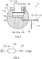
- FIG. 3 is a diagram for illustrating the structure for supply of compressed air.
- the marine engine 100 includes the air pump 190, an air pipe 192, an accumulator 194, and an air valve 196.
- the air pump 190 is connected to the air port 122a of the cylinder cover 122 by the air pipe 192.
- the accumulator 194 is provided on the air pipe 192.
- the air pump 190 is configured to compress the air sucked from the outside, and to feed out the compressed air to the accumulator 194.
- the fed-out compressed air is stored (accumulated) in the accumulator 194.
- the air valve 196 is provided on the air pipe 192 between the accumulator 194 and the air port 122a.
- the air valve 196 is, for example, an electromagnetic valve.
- the compressed air accumulated in the accumulator 194 is used to start the marine engine 100 and to stop a ship in an emergency. A detailed description of the compressed air is given later.
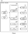
- FIG. 4 is a functional block diagram for illustrating the marine engine 100.
- a configuration relating to control for the compression ratio changing mechanism V, the fuel injection valve 140, and the air valve 196 is mainly illustrated.
- the marine engine 100 includes a control device 200.
- the control device 200 is formed of, for example, an engine control unit (ECU).
- the control device 200 is formed of a central processing unit (CPU), a ROM storing programs and the like, a RAM serving as a work area, and the like, and is configured to control the entire marine engine 100.
- the control device 200 functions as a compression ratio controller 202, a fuel controller 204, an exhaust controller 206, and an air controller 208.
- the compression ratio controller 202 is configured to control the hydraulic pump 172 and the selector valve 178, to thereby move the top dead center position of the piston 112. For example, during normal navigation, the compression ratio controller 202 controls the top dead center position of the piston 112 such that a compression ratio determined in accordance with an operation condition is achieved.
- the fuel controller 204 is configured to control the fuel injection valve 140, to thereby control an injection amount and an injection timing of the fuel. For example, during the normal navigation, the fuel controller 204 controls the fuel injection valve 140 such that an injection amount and an injection timing of the fuel determined in accordance with the operation condition are achieved.
- the exhaust controller 206 is configured to control the exhaust valve drive device 130, to thereby open and close the exhaust valve 128. For example, during the normal navigation, the exhaust controller 206 controls the exhaust valve drive device 130 such that an opening timing and a closing timing of the exhaust valve 128 determined in accordance with the operation condition are achieved.
- the air controller 208 is configured to control the air valve 196, to thereby supply the compressed air to the combustion chamber 126.
- the air controller 208 supplies the compressed air to the combustion chamber 126.
- the air controller 208 supplies the compressed air to the combustion chamber 126 at a timing at which rotation of the crankshaft 120 in a forward rotation direction (rotation direction for the ship to move forward) is promoted. That is, the air controller 208 supplies the compressed air to the combustion chamber 126 in the downstroke of the piston 112.
- the piston 112 is pressed by the compressed air, thereby being moved in the stroke direction. After reciprocation of the piston 112 starts, the fuel is injected by the fuel injection valve 140.
- the marine engine 100 includes a signal output unit 210.
- the signal output unit 210 is formed of, for example, an operation device such as an emergency button.
- the signal output unit 210 is configured to output a crash astern signal in accordance with operation input.
- the crash astern signal is a signal for instructing the marine engine 100 to perform an emergency stop of the ship. Description has been given of the case in which the signal output unit 210 outputs the crash astern signal in accordance with the operation input. However, for example, when it is determined that the emergency stop of the ship is required based on various sensor output, the signal output unit 210 may output the crash astern signal.
- FIG. 5(a) is a graph for showing the emergency stop of the ship.
- FIG. 5(b) is a graph for showing a comparative example.
- the crash astern signal is output (time point ti).
- the fuel controller 204 immediately stops the supply of the fuel to the combustion chamber 126.
- the compression ratio controller 202 operates the hydraulic pump 172 while the selector valve 178 is closed. As a result, forcible feeding of the working oil into the hydraulic chamber 154a is started. The forcible feeding is completed at a time point t c , and the top dead center position of the piston 112 moves most toward the exhaust valve 128 side. That is, the compression ratio becomes highest.
- FIG. 6 is a graph for showing compression pressure of gas compressed by the piston 112 in the combustion chamber 126.
- work of the piston 112 increases in the upstroke of the piston 112 in a case of a high compression ratio indicated by a solid line. Accordingly, a braking force increases, and a decrease speed of the engine rotation speed increases.
- crank angle EO is given as a crank angle at which the exhaust valve 128 is opened at the above-mentioned time point t 1 .
- the exhaust controller 206 advances the crank angle at which the exhaust valve 128 is opened (for example, to a crank angle EO') within a range of the downstroke of the piston 112 when the crash astern signal is output.
- the air in the combustion chamber 126 presses the piston 112 while expanding in the downstroke of the piston 112. Accordingly, the decrease in engine rotation speed is hindered.
- the crank angle at which the exhaust valve 128 is opened is advanced as described above, the work of pressing the piston 112 by the air in the combustion chamber 126 is reduced by an amount corresponding to an angle X representing a difference between the crank angle EO and the crank angle EO' (crosshatching of FIG. 6 indicates an example of the reduced amount). Accordingly, the decrease speed of the engine rotation speed increases.
- a forward movement rotation speed n2 falls below a first threshold value set in advance at a time point t 2 shown in FIG. 5(a) .
- the air controller 208 supplies the compressed air to the combustion chamber 126 at a timing at which the rotation of the crankshaft 120 in the backward rotation direction (rotation direction for the ship to move backward) is promoted. That is, the air controller 208 supplies the compressed air to the combustion chamber 126 in the upstroke of the piston 112.
- backward movement rotation speed (the engine rotation speed in a backward movement direction is hereinafter referred to as "backward movement rotation speed") exceeds a second threshold value set in advance
- the fuel controller 204 resumes the injection of the fuel by the fuel injection valve 140.
- the backward movement rotation speed exceeds a third threshold value set in advance at a time point t 4
- the marine engine 100 is stopped, and the ship accordingly stops.
- the compression ratio controller 202 moves the top dead center position of the piston 112 toward the opposite side of the bottom dead center position. Moreover, the crank angle at which the exhaust valve 128 is opened is advanced. As a result, the braking force increases. Meanwhile, in the comparative example shown in FIG. 5(b) , any one of the increase in compression ratio and the advance of the crank angle at which the exhaust valve 128 is opened is not executed. Compared with time points t 2 ', t 3 ', and t 4 ' of that comparative example, the time points t 2 , t 3 , and t 4 shown in FIG. 5(a) are advanced. Accordingly, a quicker stop of the ship in an emergency is achieved.
- the compression ratio controller 202 maintains the high compression ratio even after the backward rotation operation starts. Therefore, the small volume of the combustion chamber 126 is maintained, and a consumption amount of the compressed air is thus suppressed. As a result, energy consumption of the air pump 190 is suppressed. Further, when the backward rotation operation starts, ignitability of the fuel increases due to the high compression ratio, and stability is thus achieved.
- the compression ratio controller 202 is configured to move the top dead center position of the piston 112 toward the opposite side of the bottom dead center position when there is a margin for increasing the compression ratio.
- the compression ratio controller 202 may be configured to move the top dead center position of the piston 112 toward the opposite side of the bottom dead center position when the top dead center position of the piston 112 is on the bottom dead center position side with respect to a predetermined position set in advance. That is, a position at which the compression ratio is the highest or a position at which the compression ratio is lower than the highest compression ratio may be set as the predetermined position set in advance.
- FIG. 7 is a flowchart for illustrating a flow of ship stopping processing in an emergency. The processing illustrated in FIG. 7 is repeated at predetermined cycles.
- the fuel controller 204 determines whether or not the crash astern signal is output (Step S300). When the crash astern signal is output (YES in Step S300), the processing proceeds to Step S302. When the crash astern signal is not output (NO in Step S300), this ship stopping processing is finished.
- the fuel controller 204 stops the supply of the fuel to the combustion chamber 126 (Step S302).
- the compression ratio controller 202 moves the top dead center position of the piston 112 most toward the exhaust valve 128 side (sets the compression ratio to the highest compression ratio) (Step S304).
- the exhaust controller 206 advances the crank angle at which the exhaust valve 128 is opened within the range of the downstroke of the piston 112 (Step S306).
- the air controller 208 determines whether or not the forward movement rotation speed is lower than the first threshold value based on the signal from the crank angle sensor S (Step S308). When the forward movement rotation speed is equal to or higher than the first threshold value (NO in Step S308), the air controller 208 repeats Step S308. When the forward movement rotation speed is lower than the first threshold value (YES in Step S308), the processing proceeds to Step S310.
- the air controller 208 starts supply of braking air, which is the supply of the compressed air to the combustion chamber 126, in the upstroke of the piston 112 (Step S310).
- the fuel controller 204 determines whether or not the engine rotation speed is approximately 0 (within a predetermined range including 0) based on the signal from the crank angle sensor S (Step S312). When the engine rotation speed is not approximately 0 (NO in Step S312), the fuel controller 204 repeats Step S312. When the engine rotation speed is approximately 0 (YES in Step S312), the processing proceeds to Step S314.
- the exhaust controller 206 restores (retards) the crank angle at which the exhaust valve 128 is opened (Step S314).
- the air controller 208 starts supply of starting air, which is the supply of the compressed air to the combustion chamber 126, in the downstroke of the piston 112 (Step S316).
- the fuel controller 204 determines whether or not the backward movement rotation speed is higher than the second threshold value based on the signal from the crank angle sensor S (Step S318). When the backward movement rotation speed is equal to or lower than the second threshold value (NO in Step S318), the fuel controller 204 repeats Step S318. When the backward movement rotation speed is higher than the second threshold value (YES in Step S318), the processing proceeds to Step S320.
- the fuel controller 204 resumes the supply of the fuel to the combustion chamber 126 (Step S320).
- the fuel controller 204 determines whether or not the backward movement rotation speed is higher than the third threshold value based on the signal from the crank angle sensor S (Step S322). When the backward movement rotation speed is equal to or lower than the third threshold value (NO in Step S322), the fuel controller 204 repeats Step S322. When the backward movement rotation speed is higher than the third threshold value (YES in Step S322), the processing proceeds to Step S324.
- the control device 200 executes the ship stopping processing (Step S324).
- the fuel controller 204 stops the supply of the fuel to the combustion chamber 126.
- the air controller 208 stops the supply of the compressed air to the combustion chamber 126.
- the description is given of the marine engine 100 of the two-cycle type, the uniflow scavenging type, and the crosshead type as an example.
- the type of the engine is not limited to the two-cycle type, the uniflow scavenging type, and the crosshead type. It is only required that the present disclosure be applied to a marine engine.
- a gas fuel may be used.
- a gas fuel injection valve is provided in a vicinity of the scavenging port 110a, or a portion of the cylinder 110 from the scavenging port 110a to the cylinder cover 122.
- the fuel gas is injected from the gas fuel injection valve, and then flows into the cylinder 110.
- a mixture of the fuel gas and active gas is ignited by combustion heat of the liquid fuel, and is then combusted.
- the fuel gas is gasified LNG, LPG (liquified petroleum gas), light oil, heavy oil, or the like.
- the marine engine 100 may be, for example, of the dual fuel type, which selects a gas fuel or a liquid fuel to be used.
- the description is given of the case in which the exhaust controller 206 advances the crank angle at which the exhaust valve 128 is opened within the range of the downstroke of the piston 112 when the crash astern signal is output.
- the exhaust controller 206 is not required to change the crank angle at which the exhaust valve 128 is opened.
- variable compression ratio mechanism V may have any configuration as long as the mechanism changes the top dead center position of the piston 112 so as to be able to change the compression ratio.
- a hydraulic pressure generation device as described in JP2016-211462A may be provided in place of the hydraulic pressure pump 172.
- the output of the turbocharger C is not fully secured, and hence an electric auxiliary blower is thus used up to a degree of a medium load.
- a compression ratio is increased to be high by the compression ratio changing mechanism V, thereby suppressing a decrease in quality of the combustion even when the amount of the active gas is small.
- a use amount of the auxiliary blower is reduced, thereby being capable of reducing power consumption.
- auxiliary blower only a small rated air capacity is required in the auxiliary blower, and a size of the auxiliary blower, a size of a generator configured to supply electric power to the auxiliary blower, and a size of a drive engine for the generator are thus reduced.
- the present discloser can be applied to the marine engine.
Landscapes
- Engineering & Computer Science (AREA)
- Chemical & Material Sciences (AREA)
- Combustion & Propulsion (AREA)
- Mechanical Engineering (AREA)
- General Engineering & Computer Science (AREA)
- Ocean & Marine Engineering (AREA)
- Output Control And Ontrol Of Special Type Engine (AREA)
- Electrical Control Of Air Or Fuel Supplied To Internal-Combustion Engine (AREA)
Claims (2)
- Schiffsmotor mit:einer Luftsteuerungseinrichtung, die konfiguriert ist, einer Brennkammer in einem Aufwärtshub eines Kolbens, nachdem ein Aufprall-Achtern-Signal ausgegeben ist, Druckluft zuzuführen; undeiner Brennstoffsteuerungseinrichtung, die konfiguriert ist, eine Zufuhr von Brennstoff zu der Brennkammer zu stoppen, wenn das Aufprall-Achtern-Signal ausgegeben ist, und die Zufuhr des Brennstoffs nach einer Rückwärtsdrehung einer Kurbelwelle fortzusetzen; gekennzeichnet durcheine Verdichtungsverhältnis-Steuerungseinrichtung, die konfiguriert ist, eine Obere-Totpunkt-Position des Kolbens zu einer entgegengesetzten Seite einer Untere-Totpunkt-Position des Kolbens zu bewegen, wenn das Aufprall-Achtern-Signal ausgegeben ist, und die Obere-Totpunkt-Position des Kolbens bezüglich einer vorbestimmten Position, die vorab eingestellt ist, auf der Seite der Untere-Totpunkt-Position ist.
- Schiffsmotor nach Anspruch 1, ferner mit einer Abgassteuerungseinrichtung, die konfiguriert ist, einen Kurbelwinkel, bei welchem ein Abgasventil geöffnet ist, vorwärts innerhalb eines Bereichs eines Abwärtshubs des Kolbens zu bewegen, wenn das Aufprall-Achtern-Signal ausgegeben ist.
Applications Claiming Priority (2)
| Application Number | Priority Date | Filing Date | Title |
|---|---|---|---|
| JP2018050006A JP2019157845A (ja) | 2018-03-16 | 2018-03-16 | 舶用エンジン |
| PCT/JP2019/010586 WO2019177106A1 (ja) | 2018-03-16 | 2019-03-14 | 舶用エンジン |
Publications (4)
| Publication Number | Publication Date |
|---|---|
| EP3767093A1 EP3767093A1 (de) | 2021-01-20 |
| EP3767093A4 EP3767093A4 (de) | 2021-12-22 |
| EP3767093B1 true EP3767093B1 (de) | 2022-12-14 |
| EP3767093B8 EP3767093B8 (de) | 2023-03-01 |
Family
ID=67907287
Family Applications (1)
| Application Number | Title | Priority Date | Filing Date |
|---|---|---|---|
| EP19767910.3A Active EP3767093B8 (de) | 2018-03-16 | 2019-03-14 | Schiffsmotor |
Country Status (7)
| Country | Link |
|---|---|
| US (1) | US11105281B2 (de) |
| EP (1) | EP3767093B8 (de) |
| JP (1) | JP2019157845A (de) |
| KR (1) | KR102290922B1 (de) |
| CN (1) | CN111886406B (de) |
| DK (1) | DK3767093T3 (de) |
| WO (1) | WO2019177106A1 (de) |
Families Citing this family (2)
| Publication number | Priority date | Publication date | Assignee | Title |
|---|---|---|---|---|
| EP3767089B1 (de) * | 2018-03-16 | 2023-05-03 | Ihi Corporation | Motor |
| JP7507698B2 (ja) * | 2021-01-13 | 2024-06-28 | 株式会社三井E&S Du | エンジン |
Family Cites Families (23)
| Publication number | Priority date | Publication date | Assignee | Title |
|---|---|---|---|---|
| JPS58222974A (ja) * | 1982-06-22 | 1983-12-24 | Ishikawajima Harima Heavy Ind Co Ltd | デイ−ゼル機関の始動空気制御装置 |
| JPS60108533A (ja) * | 1983-11-16 | 1985-06-14 | Mitsui Eng & Shipbuild Co Ltd | 舶用デイ−ゼル機関におけるクラツシユ・アスタ−ン装置 |
| JPH05332228A (ja) | 1992-06-03 | 1993-12-14 | Mitsubishi Heavy Ind Ltd | ディーゼル機関用起動弁の駆動装置 |
| EP1632658A1 (de) * | 1996-10-25 | 2006-03-08 | Clyde C. Bryant | Verbesserte Brennkraftmaschine und Arbeitstakte |
| JP3705390B2 (ja) | 1997-02-26 | 2005-10-12 | ヤマハマリン株式会社 | 船舶用エンジンの制御装置 |
| JP2004225605A (ja) * | 2003-01-23 | 2004-08-12 | Nissan Motor Co Ltd | エンジンのegr制御装置 |
| JP4484604B2 (ja) * | 2004-07-12 | 2010-06-16 | ヤンマー株式会社 | エンジンの燃料噴射量制御方法およびこれを用いたエンジン運転状態判別方法 |
| WO2006006375A1 (ja) | 2004-07-12 | 2006-01-19 | Yanmar Co., Ltd. | 多気筒エンジンの燃料制御方法、エンジンの燃料噴射量制御方法およびこれを用いたエンジン運転状態判別方法、複数エンジンの推進装置、舶用減速逆転機付エンジンにおけるクラッシュアスターン時燃料噴射制御方法 |
| JP4532190B2 (ja) | 2004-07-12 | 2010-08-25 | ヤンマー株式会社 | 舶用減速逆転機付エンジンにおけるクラッシュアスターン時燃料噴射制御方法 |
| JP4533856B2 (ja) * | 2006-03-07 | 2010-09-01 | 日産自動車株式会社 | 内燃機関の圧縮比制御装置及び圧縮比制御方法 |
| JP2008260413A (ja) | 2007-04-12 | 2008-10-30 | Kokusan Denki Co Ltd | 船舶用エンジン緊急停止装置及び船舶用事故判定装置 |
| JP2009115102A (ja) * | 2009-03-04 | 2009-05-28 | Honda Motor Co Ltd | 内燃機関の制御装置 |
| JP2012007515A (ja) | 2010-06-23 | 2012-01-12 | Toyota Motor Corp | 圧縮比可変機構を備える内燃機関の制御装置 |
| JP5874236B2 (ja) | 2011-08-10 | 2016-03-02 | いすゞ自動車株式会社 | ディーゼルエンジン |
| JP6137341B2 (ja) * | 2014-01-20 | 2017-05-31 | 株式会社Ihi | クロスヘッド型エンジン |
| DK178404B1 (en) | 2014-07-17 | 2016-02-08 | Man Diesel & Turbo Deutschland | Large slow-running turbocharged two-stroke self-igniting internal combustion engine with a starting air system |
| JP6633270B2 (ja) * | 2014-10-30 | 2020-01-22 | 株式会社Ihi | ユニフロー掃気式2サイクルエンジン |
| KR101901428B1 (ko) | 2014-10-30 | 2018-09-21 | 가부시키가이샤 아이에이치아이 | 유니플로 소기식 2사이클 엔진 |
| EP3015664B1 (de) * | 2014-10-31 | 2017-06-28 | Winterthur Gas & Diesel AG | Umsteuerverfahren zum schnellen umsteuern eines motors, computerprogrammprodukt, sowie motor |
| JP6451486B2 (ja) | 2015-05-11 | 2019-01-16 | 株式会社Ihi | 油圧発生装置およびクロスヘッド型エンジン |
| JP6447410B2 (ja) | 2015-08-13 | 2019-01-09 | 日産自動車株式会社 | 可変圧縮比機構を備えた内燃機関の制御方法及び制御装置 |
| JP6194449B1 (ja) * | 2016-03-22 | 2017-09-13 | 三菱重工業株式会社 | Egrシステム及び船舶の運転方法 |
| JP6817764B2 (ja) | 2016-09-23 | 2021-01-20 | 株式会社カネカ | 太陽電池セル、及び太陽電池セルの製造方法 |
-
2018
- 2018-03-16 JP JP2018050006A patent/JP2019157845A/ja active Pending
-
2019
- 2019-03-14 EP EP19767910.3A patent/EP3767093B8/de active Active
- 2019-03-14 KR KR1020207026633A patent/KR102290922B1/ko active Active
- 2019-03-14 CN CN201980019826.3A patent/CN111886406B/zh active Active
- 2019-03-14 DK DK19767910.3T patent/DK3767093T3/da active
- 2019-03-14 WO PCT/JP2019/010586 patent/WO2019177106A1/ja not_active Ceased
-
2020
- 2020-09-15 US US17/021,357 patent/US11105281B2/en active Active
Also Published As
| Publication number | Publication date |
|---|---|
| JP2019157845A (ja) | 2019-09-19 |
| CN111886406B (zh) | 2022-11-22 |
| CN111886406A (zh) | 2020-11-03 |
| EP3767093A4 (de) | 2021-12-22 |
| US20200408160A1 (en) | 2020-12-31 |
| KR102290922B1 (ko) | 2021-08-17 |
| DK3767093T3 (da) | 2023-01-16 |
| WO2019177106A1 (ja) | 2019-09-19 |
| US11105281B2 (en) | 2021-08-31 |
| KR20200115649A (ko) | 2020-10-07 |
| EP3767093B8 (de) | 2023-03-01 |
| EP3767093A1 (de) | 2021-01-20 |
Similar Documents
| Publication | Publication Date | Title |
|---|---|---|
| US10087831B2 (en) | Engine | |
| JP2002511130A (ja) | 自由ピストン内燃機関 | |
| KR101959852B1 (ko) | 대형 2 행정 압축 점화 내연기관용 실린더 윤활 장치 | |
| EP3767093B1 (de) | Schiffsmotor | |
| US11199140B2 (en) | Engine | |
| US11306649B2 (en) | Engine system | |
| US20200362774A1 (en) | Compression ratio varying mechanism | |
| JP7173200B2 (ja) | ユニフロー掃気式2サイクルエンジン | |
| US11174826B2 (en) | Engine | |
| US11053865B2 (en) | Compression ratio control device and engine | |
| EP3719273B1 (de) | Vorrichtung mit variabler kompression und motorsystem | |
| EP3715600B1 (de) | Vorrichtung mit variabler kompression und motorsystem | |
| JP2019157847A (ja) | エンジン |
Legal Events
| Date | Code | Title | Description |
|---|---|---|---|
| STAA | Information on the status of an ep patent application or granted ep patent |
Free format text: STATUS: THE INTERNATIONAL PUBLICATION HAS BEEN MADE |
|
| PUAI | Public reference made under article 153(3) epc to a published international application that has entered the european phase |
Free format text: ORIGINAL CODE: 0009012 |
|
| STAA | Information on the status of an ep patent application or granted ep patent |
Free format text: STATUS: REQUEST FOR EXAMINATION WAS MADE |
|
| 17P | Request for examination filed |
Effective date: 20200831 |
|
| AK | Designated contracting states |
Kind code of ref document: A1 Designated state(s): AL AT BE BG CH CY CZ DE DK EE ES FI FR GB GR HR HU IE IS IT LI LT LU LV MC MK MT NL NO PL PT RO RS SE SI SK SM TR |
|
| AX | Request for extension of the european patent |
Extension state: BA ME |
|
| DAV | Request for validation of the european patent (deleted) | ||
| DAX | Request for extension of the european patent (deleted) | ||
| A4 | Supplementary search report drawn up and despatched |
Effective date: 20211122 |
|
| RIC1 | Information provided on ipc code assigned before grant |
Ipc: F02D 41/04 20060101ALI20211116BHEP Ipc: F02B 25/04 20060101ALI20211116BHEP Ipc: F02D 41/22 20060101ALI20211116BHEP Ipc: F02D 17/04 20060101ALI20211116BHEP Ipc: F02D 13/02 20060101ALI20211116BHEP Ipc: F02D 17/02 20060101ALI20211116BHEP Ipc: F02D 17/00 20060101ALI20211116BHEP Ipc: F02B 75/04 20060101ALI20211116BHEP Ipc: F02D 15/02 20060101AFI20211116BHEP |
|
| GRAP | Despatch of communication of intention to grant a patent |
Free format text: ORIGINAL CODE: EPIDOSNIGR1 |
|
| STAA | Information on the status of an ep patent application or granted ep patent |
Free format text: STATUS: GRANT OF PATENT IS INTENDED |
|
| INTG | Intention to grant announced |
Effective date: 20220914 |
|
| GRAS | Grant fee paid |
Free format text: ORIGINAL CODE: EPIDOSNIGR3 |
|
| GRAA | (expected) grant |
Free format text: ORIGINAL CODE: 0009210 |
|
| STAA | Information on the status of an ep patent application or granted ep patent |
Free format text: STATUS: THE PATENT HAS BEEN GRANTED |
|
| AK | Designated contracting states |
Kind code of ref document: B1 Designated state(s): AL AT BE BG CH CY CZ DE DK EE ES FI FR GB GR HR HU IE IS IT LI LT LU LV MC MK MT NL NO PL PT RO RS SE SI SK SM TR |
|
| REG | Reference to a national code |
Ref country code: GB Ref legal event code: FG4D |
|
| REG | Reference to a national code |
Ref country code: CH Ref legal event code: EP |
|
| REG | Reference to a national code |
Ref country code: DE Ref legal event code: R096 Ref document number: 602019023205 Country of ref document: DE |
|
| REG | Reference to a national code |
Ref country code: IE Ref legal event code: FG4D |
|
| REG | Reference to a national code |
Ref country code: AT Ref legal event code: REF Ref document number: 1537791 Country of ref document: AT Kind code of ref document: T Effective date: 20230115 |
|
| REG | Reference to a national code |
Ref country code: DK Ref legal event code: T3 Effective date: 20230113 |
|
| REG | Reference to a national code |
Ref country code: CH Ref legal event code: PK Free format text: BERICHTIGUNG B8 |
|
| RAP4 | Party data changed (patent owner data changed or rights of a patent transferred) |
Owner name: IHI CORPORATION |
|
| REG | Reference to a national code |
Ref country code: LT Ref legal event code: MG9D |
|
| REG | Reference to a national code |
Ref country code: NL Ref legal event code: MP Effective date: 20221214 |
|
| PG25 | Lapsed in a contracting state [announced via postgrant information from national office to epo] |
Ref country code: SE Free format text: LAPSE BECAUSE OF FAILURE TO SUBMIT A TRANSLATION OF THE DESCRIPTION OR TO PAY THE FEE WITHIN THE PRESCRIBED TIME-LIMIT Effective date: 20221214 Ref country code: NO Free format text: LAPSE BECAUSE OF FAILURE TO SUBMIT A TRANSLATION OF THE DESCRIPTION OR TO PAY THE FEE WITHIN THE PRESCRIBED TIME-LIMIT Effective date: 20230314 Ref country code: LT Free format text: LAPSE BECAUSE OF FAILURE TO SUBMIT A TRANSLATION OF THE DESCRIPTION OR TO PAY THE FEE WITHIN THE PRESCRIBED TIME-LIMIT Effective date: 20221214 Ref country code: FI Free format text: LAPSE BECAUSE OF FAILURE TO SUBMIT A TRANSLATION OF THE DESCRIPTION OR TO PAY THE FEE WITHIN THE PRESCRIBED TIME-LIMIT Effective date: 20221214 |
|
| REG | Reference to a national code |
Ref country code: AT Ref legal event code: MK05 Ref document number: 1537791 Country of ref document: AT Kind code of ref document: T Effective date: 20221214 |
|
| PG25 | Lapsed in a contracting state [announced via postgrant information from national office to epo] |
Ref country code: RS Free format text: LAPSE BECAUSE OF FAILURE TO SUBMIT A TRANSLATION OF THE DESCRIPTION OR TO PAY THE FEE WITHIN THE PRESCRIBED TIME-LIMIT Effective date: 20221214 Ref country code: LV Free format text: LAPSE BECAUSE OF FAILURE TO SUBMIT A TRANSLATION OF THE DESCRIPTION OR TO PAY THE FEE WITHIN THE PRESCRIBED TIME-LIMIT Effective date: 20221214 Ref country code: HR Free format text: LAPSE BECAUSE OF FAILURE TO SUBMIT A TRANSLATION OF THE DESCRIPTION OR TO PAY THE FEE WITHIN THE PRESCRIBED TIME-LIMIT Effective date: 20221214 Ref country code: GR Free format text: LAPSE BECAUSE OF FAILURE TO SUBMIT A TRANSLATION OF THE DESCRIPTION OR TO PAY THE FEE WITHIN THE PRESCRIBED TIME-LIMIT Effective date: 20230315 |
|
| PG25 | Lapsed in a contracting state [announced via postgrant information from national office to epo] |
Ref country code: NL Free format text: LAPSE BECAUSE OF FAILURE TO SUBMIT A TRANSLATION OF THE DESCRIPTION OR TO PAY THE FEE WITHIN THE PRESCRIBED TIME-LIMIT Effective date: 20221214 |
|
| PG25 | Lapsed in a contracting state [announced via postgrant information from national office to epo] |
Ref country code: SM Free format text: LAPSE BECAUSE OF FAILURE TO SUBMIT A TRANSLATION OF THE DESCRIPTION OR TO PAY THE FEE WITHIN THE PRESCRIBED TIME-LIMIT Effective date: 20221214 Ref country code: RO Free format text: LAPSE BECAUSE OF FAILURE TO SUBMIT A TRANSLATION OF THE DESCRIPTION OR TO PAY THE FEE WITHIN THE PRESCRIBED TIME-LIMIT Effective date: 20221214 Ref country code: PT Free format text: LAPSE BECAUSE OF FAILURE TO SUBMIT A TRANSLATION OF THE DESCRIPTION OR TO PAY THE FEE WITHIN THE PRESCRIBED TIME-LIMIT Effective date: 20230414 Ref country code: ES Free format text: LAPSE BECAUSE OF FAILURE TO SUBMIT A TRANSLATION OF THE DESCRIPTION OR TO PAY THE FEE WITHIN THE PRESCRIBED TIME-LIMIT Effective date: 20221214 Ref country code: EE Free format text: LAPSE BECAUSE OF FAILURE TO SUBMIT A TRANSLATION OF THE DESCRIPTION OR TO PAY THE FEE WITHIN THE PRESCRIBED TIME-LIMIT Effective date: 20221214 Ref country code: CZ Free format text: LAPSE BECAUSE OF FAILURE TO SUBMIT A TRANSLATION OF THE DESCRIPTION OR TO PAY THE FEE WITHIN THE PRESCRIBED TIME-LIMIT Effective date: 20221214 Ref country code: AT Free format text: LAPSE BECAUSE OF FAILURE TO SUBMIT A TRANSLATION OF THE DESCRIPTION OR TO PAY THE FEE WITHIN THE PRESCRIBED TIME-LIMIT Effective date: 20221214 |
|
| REG | Reference to a national code |
Ref country code: DE Ref legal event code: R081 Ref document number: 602019023205 Country of ref document: DE Owner name: MITSUI E&S DU CO., LTD., AIOI-SHI, JP Free format text: FORMER OWNER: IHI CORPORATION, TOKYO, JP |
|
| PG25 | Lapsed in a contracting state [announced via postgrant information from national office to epo] |
Ref country code: SK Free format text: LAPSE BECAUSE OF FAILURE TO SUBMIT A TRANSLATION OF THE DESCRIPTION OR TO PAY THE FEE WITHIN THE PRESCRIBED TIME-LIMIT Effective date: 20221214 Ref country code: PL Free format text: LAPSE BECAUSE OF FAILURE TO SUBMIT A TRANSLATION OF THE DESCRIPTION OR TO PAY THE FEE WITHIN THE PRESCRIBED TIME-LIMIT Effective date: 20221214 Ref country code: IS Free format text: LAPSE BECAUSE OF FAILURE TO SUBMIT A TRANSLATION OF THE DESCRIPTION OR TO PAY THE FEE WITHIN THE PRESCRIBED TIME-LIMIT Effective date: 20230414 Ref country code: AL Free format text: LAPSE BECAUSE OF FAILURE TO SUBMIT A TRANSLATION OF THE DESCRIPTION OR TO PAY THE FEE WITHIN THE PRESCRIBED TIME-LIMIT Effective date: 20221214 |
|
| REG | Reference to a national code |
Ref country code: DE Ref legal event code: R097 Ref document number: 602019023205 Country of ref document: DE |
|
| PLBE | No opposition filed within time limit |
Free format text: ORIGINAL CODE: 0009261 |
|
| STAA | Information on the status of an ep patent application or granted ep patent |
Free format text: STATUS: NO OPPOSITION FILED WITHIN TIME LIMIT |
|
| PG25 | Lapsed in a contracting state [announced via postgrant information from national office to epo] |
Ref country code: MC Free format text: LAPSE BECAUSE OF FAILURE TO SUBMIT A TRANSLATION OF THE DESCRIPTION OR TO PAY THE FEE WITHIN THE PRESCRIBED TIME-LIMIT Effective date: 20221214 |
|
| 26N | No opposition filed |
Effective date: 20230915 |
|
| GBPC | Gb: european patent ceased through non-payment of renewal fee |
Effective date: 20230314 |
|
| PG25 | Lapsed in a contracting state [announced via postgrant information from national office to epo] |
Ref country code: SI Free format text: LAPSE BECAUSE OF FAILURE TO SUBMIT A TRANSLATION OF THE DESCRIPTION OR TO PAY THE FEE WITHIN THE PRESCRIBED TIME-LIMIT Effective date: 20221214 |
|
| REG | Reference to a national code |
Ref country code: BE Ref legal event code: MM Effective date: 20230331 |
|
| PG25 | Lapsed in a contracting state [announced via postgrant information from national office to epo] |
Ref country code: LU Free format text: LAPSE BECAUSE OF NON-PAYMENT OF DUE FEES Effective date: 20230314 |
|
| REG | Reference to a national code |
Ref country code: IE Ref legal event code: MM4A |
|
| PG25 | Lapsed in a contracting state [announced via postgrant information from national office to epo] |
Ref country code: GB Free format text: LAPSE BECAUSE OF NON-PAYMENT OF DUE FEES Effective date: 20230314 |
|
| PG25 | Lapsed in a contracting state [announced via postgrant information from national office to epo] |
Ref country code: IE Free format text: LAPSE BECAUSE OF NON-PAYMENT OF DUE FEES Effective date: 20230314 Ref country code: GB Free format text: LAPSE BECAUSE OF NON-PAYMENT OF DUE FEES Effective date: 20230314 Ref country code: FR Free format text: LAPSE BECAUSE OF NON-PAYMENT OF DUE FEES Effective date: 20230331 |
|
| PG25 | Lapsed in a contracting state [announced via postgrant information from national office to epo] |
Ref country code: BE Free format text: LAPSE BECAUSE OF NON-PAYMENT OF DUE FEES Effective date: 20230331 |
|
| PG25 | Lapsed in a contracting state [announced via postgrant information from national office to epo] |
Ref country code: IT Free format text: LAPSE BECAUSE OF FAILURE TO SUBMIT A TRANSLATION OF THE DESCRIPTION OR TO PAY THE FEE WITHIN THE PRESCRIBED TIME-LIMIT Effective date: 20221214 |
|
| PG25 | Lapsed in a contracting state [announced via postgrant information from national office to epo] |
Ref country code: BG Free format text: LAPSE BECAUSE OF FAILURE TO SUBMIT A TRANSLATION OF THE DESCRIPTION OR TO PAY THE FEE WITHIN THE PRESCRIBED TIME-LIMIT Effective date: 20221214 |
|
| PG25 | Lapsed in a contracting state [announced via postgrant information from national office to epo] |
Ref country code: BG Free format text: LAPSE BECAUSE OF FAILURE TO SUBMIT A TRANSLATION OF THE DESCRIPTION OR TO PAY THE FEE WITHIN THE PRESCRIBED TIME-LIMIT Effective date: 20221214 |
|
| PGFP | Annual fee paid to national office [announced via postgrant information from national office to epo] |
Ref country code: CH Payment date: 20250401 Year of fee payment: 7 |
|
| PG25 | Lapsed in a contracting state [announced via postgrant information from national office to epo] |
Ref country code: CY Free format text: LAPSE BECAUSE OF FAILURE TO SUBMIT A TRANSLATION OF THE DESCRIPTION OR TO PAY THE FEE WITHIN THE PRESCRIBED TIME-LIMIT; INVALID AB INITIO Effective date: 20190314 |
|
| PG25 | Lapsed in a contracting state [announced via postgrant information from national office to epo] |
Ref country code: HU Free format text: LAPSE BECAUSE OF FAILURE TO SUBMIT A TRANSLATION OF THE DESCRIPTION OR TO PAY THE FEE WITHIN THE PRESCRIBED TIME-LIMIT; INVALID AB INITIO Effective date: 20190314 |
|
| PG25 | Lapsed in a contracting state [announced via postgrant information from national office to epo] |
Ref country code: TR Free format text: LAPSE BECAUSE OF FAILURE TO SUBMIT A TRANSLATION OF THE DESCRIPTION OR TO PAY THE FEE WITHIN THE PRESCRIBED TIME-LIMIT Effective date: 20221214 |
|
| REG | Reference to a national code |
Ref country code: CH Ref legal event code: U11 Free format text: ST27 STATUS EVENT CODE: U-0-0-U10-U11 (AS PROVIDED BY THE NATIONAL OFFICE) Effective date: 20260401 |
|
| PGFP | Annual fee paid to national office [announced via postgrant information from national office to epo] |
Ref country code: DE Payment date: 20260330 Year of fee payment: 8 Ref country code: DK Payment date: 20260323 Year of fee payment: 8 |